32
ESAB - Fanuc Integration manual 0740 800 224 GB 20171018 Robot integration
ESAB - Fanuc
Integration manual
0740 800 224 GB 20171018
Robot integration
TABLE OF CONTENTS
0740 800 224 © ESAB AB 2017
1 READ THIS FIRST......................................................................................... 31.1 Documentation overview ......................................................................... 3
2 INTRODUCTION ............................................................................................ 42.1 Supported equipment .............................................................................. 42.1.1 Powersource .......................................................................................... 42.1.2 Wire feeding systems ............................................................................. 42.1.3 Interface unit........................................................................................... 42.2 Schematic system design ....................................................................... 5
3 W82 ANYBUS ................................................................................................ 63.1 Fieldbus connection................................................................................. 6
4 ETHERNET IP................................................................................................ 74.1 24AP6 Fieldbus board - EtherNet IP ....................................................... 74.2 Configuration of fieldbus board - EtherNet IP ....................................... 7
5 INSTALLATION OF HARDWARE ................................................................. 85.1 Installing W82 ........................................................................................... 8
6 CONFIGURATION EXAMPLE ....................................................................... 126.1 Signals out ................................................................................................ 126.2 Signals in................................................................................................... 146.3 Cross reference Anybus .......................................................................... 18
7 FUNCTIONAL DESCRIPTION OF I/O........................................................... 247.1 Input from controller to welding equipment .......................................... 247.1.1 Weld status bits ...................................................................................... 247.1.2 Weld data number .................................................................................. 257.1.3 Numerical welding parameters............................................................... 257.2 Output from Welding Equipment to Controller...................................... 267.2.1 Weld Status Bits ..................................................................................... 267.2.2 Default error types.................................................................................. 277.2.3 Weld Data Number ................................................................................. 287.2.4 Numerical Welding Parameters.............................................................. 287.2.5 Measured Values.................................................................................... 287.2.6 Error Mask.............................................................................................. 28
8 SERVICE INSTRUCTIONS ............................................................................ 298.1 What is ESD? ............................................................................................ 29
9 SPARE PARTS .............................................................................................. 309.1 Ordering spare parts ................................................................................ 30
Rights reserved to alter specifications without notice.
1 READ THIS FIRST
0740 800 224 - 3 - © ESAB AB 2017
1 READ THIS FIRSTMaintenance and repair work must be performed by an experienced person, and electricalwork only by a trained electrician. Use only recommended replacement parts.
This service manual is intended for use by technicians with electrical/electronic training forhelp in connection with fault-tracing and repair.
Use the wiring diagram as a form of index for the description of operation. The circuit boardsare divided into numbered blocks, which are described individually in more detail in thedescription of operation. Component names in the wiring diagram are listed in the componentdescription.
Use the spare parts list as a guide to where the components are located in the equipment.The spare parts list is published as a separate document, see “SPARE PARTS”, page 30.
This manual contains details of design changes that have been made up to and includingFebruary 2017.
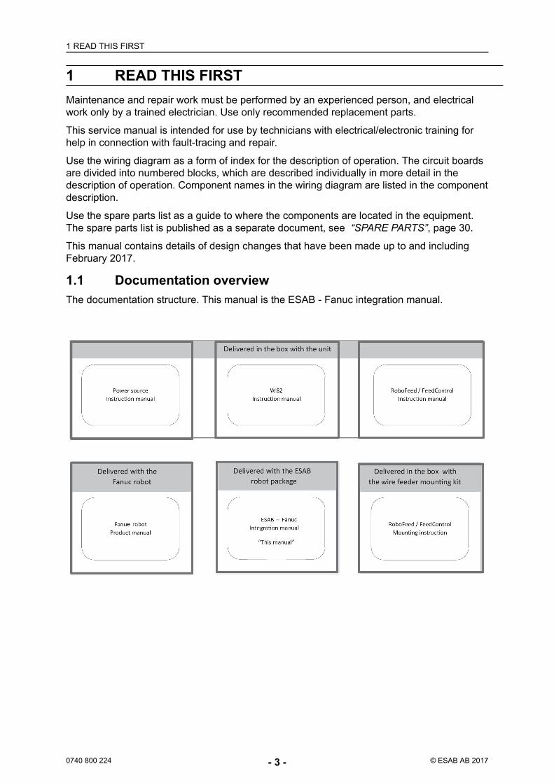
1.1 Documentation overviewThe documentation structure. This manual is the ESAB - Fanuc integration manual.
2 INTRODUCTION
0740 800 224 - 4 - © ESAB AB 2017
2 INTRODUCTIONThis manual is intended to guide a system integrator in his work when integrating ESABequipment with a Fanuc robotic solution.
2.1 Supported equipment2.1.1 PowersourceMig 5000i / 5000iw, Mig 4004i Pulse, Mig 4002c / 4002cw, Mig 5002c / 5002cw, Mig 6502c.
2.1.2 Wire feeding systemsFor hollow wrist robots like ARC Mate 100iC and ARC Mate 120iC it is recommended to usedrive unit RoboFeed 3004HW and electronic unit Feed Control Box 3004HW.
For robots with traditional upper arms it is recommended to use wire feed system RoboFeed3004W. RoboFeed 3004W contains both a mechanical drive unit and electronics.
2.1.3 Interface unitW82
The interface unit is installed between welding equipment and automation equipment, suchas robots. The W82 is available in several versions, this manual describes W82 Anybus.
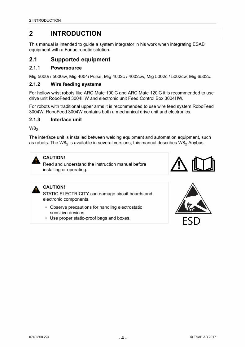
CAUTION!Read and understand the instruction manual beforeinstalling or operating.
CAUTION!STATIC ELECTRICITY can damage circuit boards andelectronic components.
• Observe precautions for handling electrostaticsensitive devices.
• Use proper static-proof bags and boxes.
2 INTRODUCTION
0740 800 224 - 5 - © ESAB AB 2017
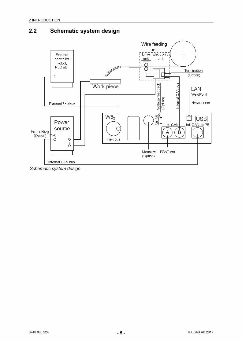
2.2 Schematic system design
Schematic system design
3 W82 ANYBUS
0740 800 224 - 6 - © ESAB AB 2017
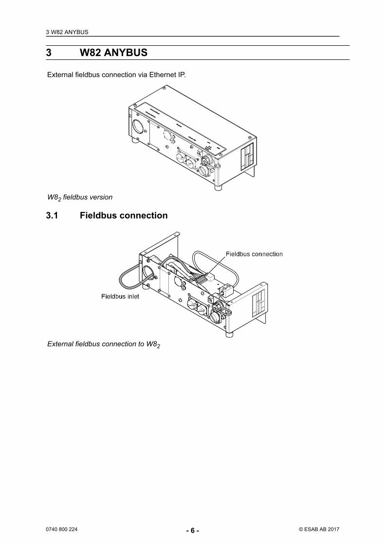
3 W82 ANYBUS
External fieldbus connection via Ethernet IP.
W82 fieldbus version
3.1 Fieldbus connection
External fieldbus connection to W82
4 ETHERNET IP
0740 800 224 - 7 - © ESAB AB 2017
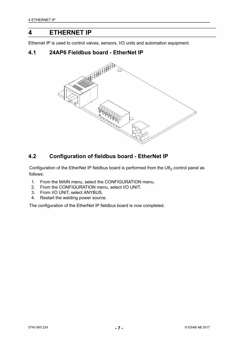
4 ETHERNET IPEthernet IP is used to control valves, sensors, I/O units and automation equipment.
4.1 24AP6 Fieldbus board - EtherNet IP
4.2 Configuration of fieldbus board - EtherNet IP
Configuration of the EtherNet IP fieldbus board is performed from the U82 control panel asfollows:
1. From the MAIN menu, select the CONFIGURATION menu.2. From the CONFIGURATION menu, select I/O UNIT.3. From I/O UNIT, select ANYBUS.4. Restart the welding power source.
The configuration of the EtherNet IP fieldbus board is now completed.
5 INSTALLATION OF HARDWARE
0740 800 224 - 8 - © ESAB AB 2017
5 INSTALLATION OF HARDWAREThe installation chapter will describe how to connect the different components. The ESABintegrated software in the robot controller should be installed by Fanuc before delivery to thesite.
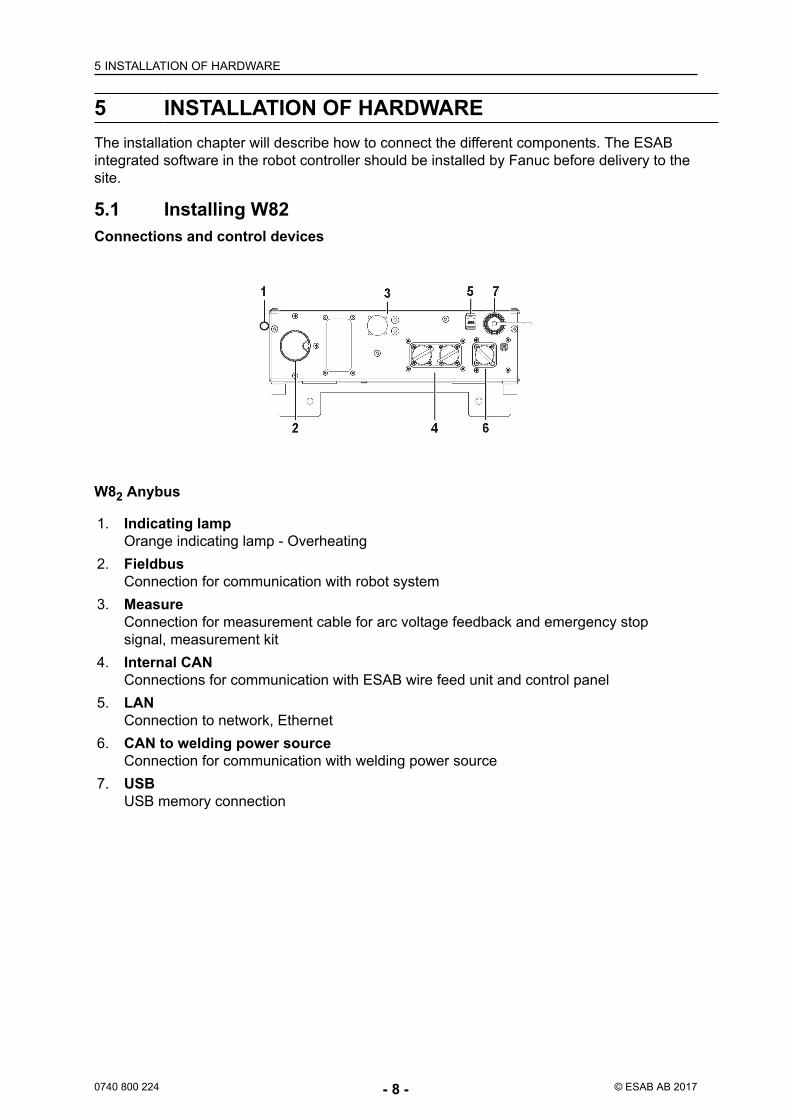
5.1 Installing W82Connections and control devices
W82 Anybus
1. Indicating lampOrange indicating lamp - Overheating
2. FieldbusConnection for communication with robot system
3. MeasureConnection for measurement cable for arc voltage feedback and emergency stopsignal, measurement kit
4. Internal CANConnections for communication with ESAB wire feed unit and control panel
5. LANConnection to network, Ethernet
6. CAN to welding power sourceConnection for communication with welding power source
7. USBUSB memory connection
5 INSTALLATION OF HARDWARE
0740 800 224 - 9 - © ESAB AB 2017
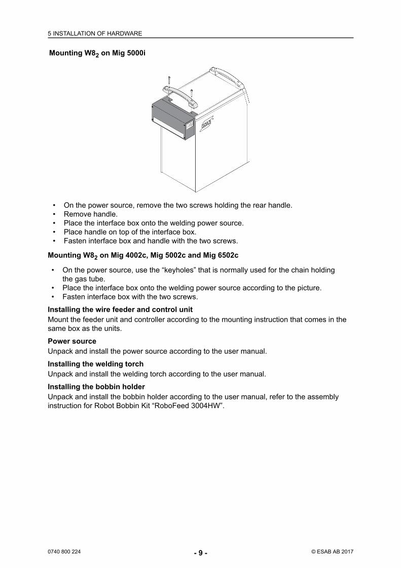
Mounting W82 on Mig 5000i
• On the power source, remove the two screws holding the rear handle.• Remove handle.• Place the interface box onto the welding power source.• Place handle on top of the interface box.• Fasten interface box and handle with the two screws.
Mounting W82 on Mig 4002c, Mig 5002c and Mig 6502c
• On the power source, use the “keyholes” that is normally used for the chain holdingthe gas tube.
• Place the interface box onto the welding power source according to the picture.• Fasten interface box with the two screws.
Installing the wire feeder and control unitMount the feeder unit and controller according to the mounting instruction that comes in thesame box as the units.
Power sourceUnpack and install the power source according to the user manual.
Installing the welding torchUnpack and install the welding torch according to the user manual.
Installing the bobbin holderUnpack and install the bobbin holder according to the user manual, refer to the assemblyinstruction for Robot Bobbin Kit “RoboFeed 3004HW”.
5 INSTALLATION OF HARDWARE
0740 800 224 - 10 - © ESAB AB 2017
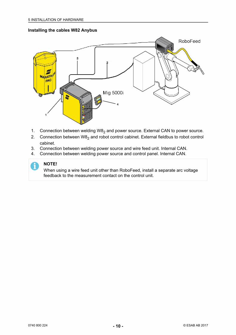
Installing the cables W82 Anybus
1. Connection between welding W82 and power source. External CAN to power source.2. Connection between W82 and robot control cabinet. External fieldbus to robot control
cabinet.3. Connection between welding power source and wire feed unit. Internal CAN.4. Connection between welding power source and control panel. Internal CAN.
NOTE!When using a wire feed unit other than RoboFeed, install a separate arc voltagefeedback to the measurement contact on the control unit.
5 INSTALLATION OF HARDWARE
0740 800 224 - 11 - © ESAB AB 2017
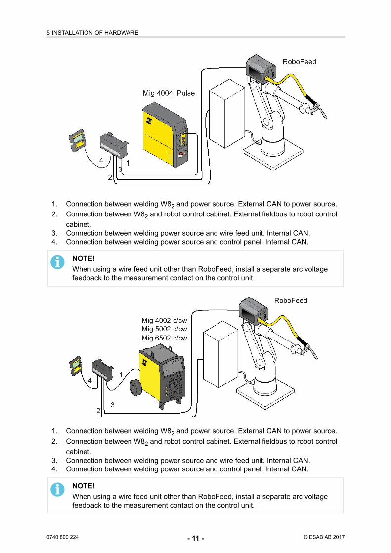
1. Connection between welding W82 and power source. External CAN to power source.2. Connection between W82 and robot control cabinet. External fieldbus to robot control
cabinet.3. Connection between welding power source and wire feed unit. Internal CAN.4. Connection between welding power source and control panel. Internal CAN.
NOTE!When using a wire feed unit other than RoboFeed, install a separate arc voltagefeedback to the measurement contact on the control unit.
6 CONFIGURATION EXAMPLE
0740 800 224 - 12 - © ESAB AB 2017
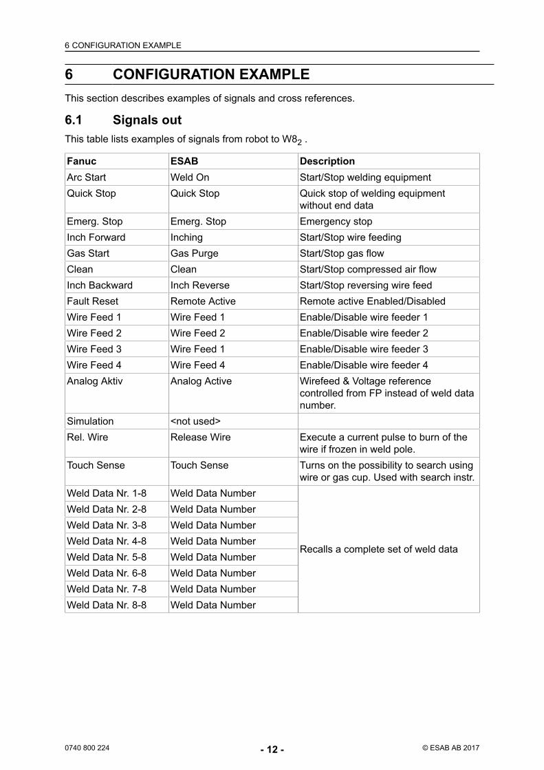
6 CONFIGURATION EXAMPLEThis section describes examples of signals and cross references.
6.1 Signals outThis table lists examples of signals from robot to W82 .
Fanuc ESAB DescriptionArc Start Weld On Start/Stop welding equipmentQuick Stop Quick Stop Quick stop of welding equipment
without end dataEmerg. Stop Emerg. Stop Emergency stopInch Forward Inching Start/Stop wire feedingGas Start Gas Purge Start/Stop gas flowClean Clean Start/Stop compressed air flowInch Backward Inch Reverse Start/Stop reversing wire feedFault Reset Remote Active Remote active Enabled/DisabledWire Feed 1 Wire Feed 1 Enable/Disable wire feeder 1Wire Feed 2 Wire Feed 2 Enable/Disable wire feeder 2Wire Feed 3 Wire Feed 1 Enable/Disable wire feeder 3Wire Feed 4 Wire Feed 4 Enable/Disable wire feeder 4Analog Aktiv Analog Active Wirefeed & Voltage reference
controlled from FP instead of weld datanumber.
Simulation <not used>Rel. Wire Release Wire Execute a current pulse to burn of the
wire if frozen in weld pole.Touch Sense Touch Sense Turns on the possibility to search using
wire or gas cup. Used with search instr.Weld Data Nr. 1-8 Weld Data Number
Recalls a complete set of weld data
Weld Data Nr. 2-8 Weld Data NumberWeld Data Nr. 3-8 Weld Data NumberWeld Data Nr. 4-8 Weld Data NumberWeld Data Nr. 5-8 Weld Data NumberWeld Data Nr. 6-8 Weld Data NumberWeld Data Nr. 7-8 Weld Data NumberWeld Data Nr. 8-8 Weld Data Number
6 CONFIGURATION EXAMPLE
0740 800 224 - 13 - © ESAB AB 2017
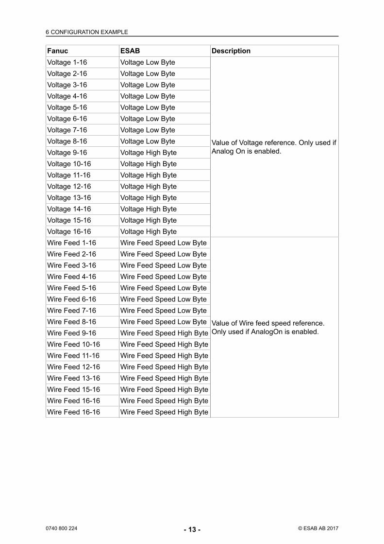
Fanuc ESAB DescriptionVoltage 1-16 Voltage Low Byte
Value of Voltage reference. Only used ifAnalog On is enabled.
Voltage 2-16 Voltage Low ByteVoltage 3-16 Voltage Low ByteVoltage 4-16 Voltage Low ByteVoltage 5-16 Voltage Low ByteVoltage 6-16 Voltage Low ByteVoltage 7-16 Voltage Low ByteVoltage 8-16 Voltage Low ByteVoltage 9-16 Voltage High ByteVoltage 10-16 Voltage High ByteVoltage 11-16 Voltage High ByteVoltage 12-16 Voltage High ByteVoltage 13-16 Voltage High ByteVoltage 14-16 Voltage High ByteVoltage 15-16 Voltage High ByteVoltage 16-16 Voltage High ByteWire Feed 1-16 Wire Feed Speed Low Byte
Value of Wire feed speed reference.Only used if AnalogOn is enabled.
Wire Feed 2-16 Wire Feed Speed Low ByteWire Feed 3-16 Wire Feed Speed Low ByteWire Feed 4-16 Wire Feed Speed Low ByteWire Feed 5-16 Wire Feed Speed Low ByteWire Feed 6-16 Wire Feed Speed Low ByteWire Feed 7-16 Wire Feed Speed Low ByteWire Feed 8-16 Wire Feed Speed Low ByteWire Feed 9-16 Wire Feed Speed High ByteWire Feed 10-16 Wire Feed Speed High ByteWire Feed 11-16 Wire Feed Speed High ByteWire Feed 12-16 Wire Feed Speed High ByteWire Feed 13-16 Wire Feed Speed High ByteWire Feed 15-16 Wire Feed Speed High ByteWire Feed 16-16 Wire Feed Speed High ByteWire Feed 16-16 Wire Feed Speed High Byte
6 CONFIGURATION EXAMPLE
0740 800 224 - 14 - © ESAB AB 2017
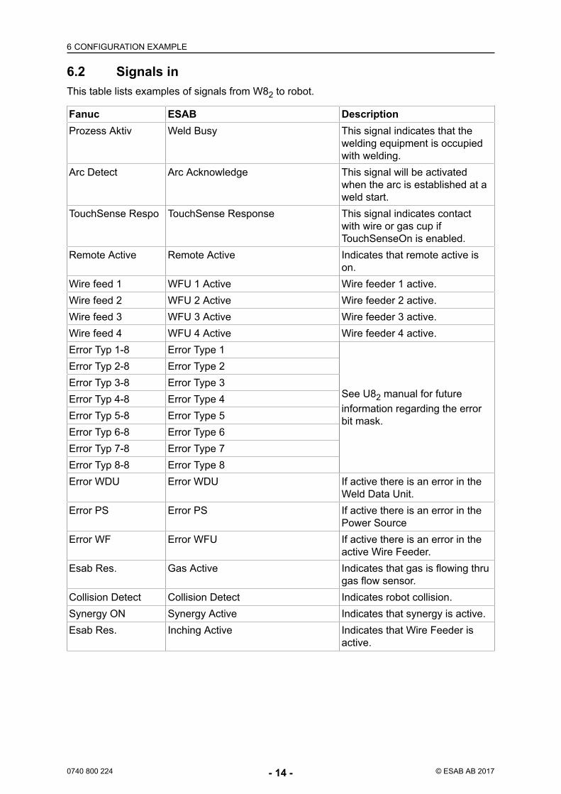
6.2 Signals inThis table lists examples of signals from W82 to robot.
Fanuc ESAB DescriptionProzess Aktiv Weld Busy This signal indicates that the
welding equipment is occupiedwith welding.
Arc Detect Arc Acknowledge This signal will be activatedwhen the arc is established at aweld start.
TouchSense Respo TouchSense Response This signal indicates contactwith wire or gas cup ifTouchSenseOn is enabled.
Remote Active Remote Active Indicates that remote active ison.
Wire feed 1 WFU 1 Active Wire feeder 1 active.Wire feed 2 WFU 2 Active Wire feeder 2 active.Wire feed 3 WFU 3 Active Wire feeder 3 active.Wire feed 4 WFU 4 Active Wire feeder 4 active.Error Typ 1-8 Error Type 1
See U82 manual for futureinformation regarding the errorbit mask.
Error Typ 2-8 Error Type 2Error Typ 3-8 Error Type 3Error Typ 4-8 Error Type 4Error Typ 5-8 Error Type 5Error Typ 6-8 Error Type 6Error Typ 7-8 Error Type 7Error Typ 8-8 Error Type 8Error WDU Error WDU If active there is an error in the
Weld Data Unit.Error PS Error PS If active there is an error in the
Power SourceError WF Error WFU If active there is an error in the
active Wire Feeder.Esab Res. Gas Active Indicates that gas is flowing thru
gas flow sensor.Collision Detect Collision Detect Indicates robot collision.Synergy ON Synergy Active Indicates that synergy is active.Esab Res. Inching Active Indicates that Wire Feeder is
active.
6 CONFIGURATION EXAMPLE
0740 800 224 - 15 - © ESAB AB 2017
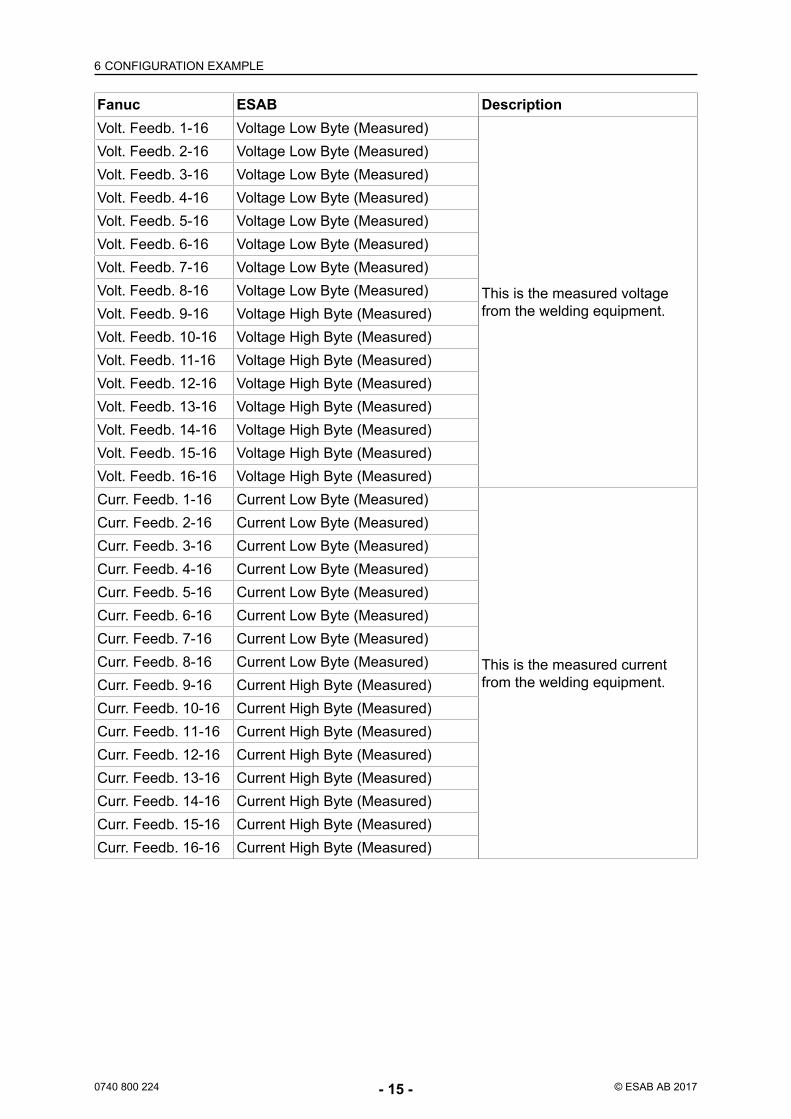
Fanuc ESAB DescriptionVolt. Feedb. 1-16 Voltage Low Byte (Measured)
This is the measured voltagefrom the welding equipment.
Volt. Feedb. 2-16 Voltage Low Byte (Measured)Volt. Feedb. 3-16 Voltage Low Byte (Measured)Volt. Feedb. 4-16 Voltage Low Byte (Measured)Volt. Feedb. 5-16 Voltage Low Byte (Measured)Volt. Feedb. 6-16 Voltage Low Byte (Measured)Volt. Feedb. 7-16 Voltage Low Byte (Measured)Volt. Feedb. 8-16 Voltage Low Byte (Measured)Volt. Feedb. 9-16 Voltage High Byte (Measured)Volt. Feedb. 10-16 Voltage High Byte (Measured)Volt. Feedb. 11-16 Voltage High Byte (Measured)Volt. Feedb. 12-16 Voltage High Byte (Measured)Volt. Feedb. 13-16 Voltage High Byte (Measured)Volt. Feedb. 14-16 Voltage High Byte (Measured)Volt. Feedb. 15-16 Voltage High Byte (Measured)Volt. Feedb. 16-16 Voltage High Byte (Measured)Curr. Feedb. 1-16 Current Low Byte (Measured)
This is the measured currentfrom the welding equipment.
Curr. Feedb. 2-16 Current Low Byte (Measured)Curr. Feedb. 3-16 Current Low Byte (Measured)Curr. Feedb. 4-16 Current Low Byte (Measured)Curr. Feedb. 5-16 Current Low Byte (Measured)Curr. Feedb. 6-16 Current Low Byte (Measured)Curr. Feedb. 7-16 Current Low Byte (Measured)Curr. Feedb. 8-16 Current Low Byte (Measured)Curr. Feedb. 9-16 Current High Byte (Measured)Curr. Feedb. 10-16 Current High Byte (Measured)Curr. Feedb. 11-16 Current High Byte (Measured)Curr. Feedb. 12-16 Current High Byte (Measured)Curr. Feedb. 13-16 Current High Byte (Measured)Curr. Feedb. 14-16 Current High Byte (Measured)Curr. Feedb. 15-16 Current High Byte (Measured)Curr. Feedb. 16-16 Current High Byte (Measured)
6 CONFIGURATION EXAMPLE
0740 800 224 - 16 - © ESAB AB 2017
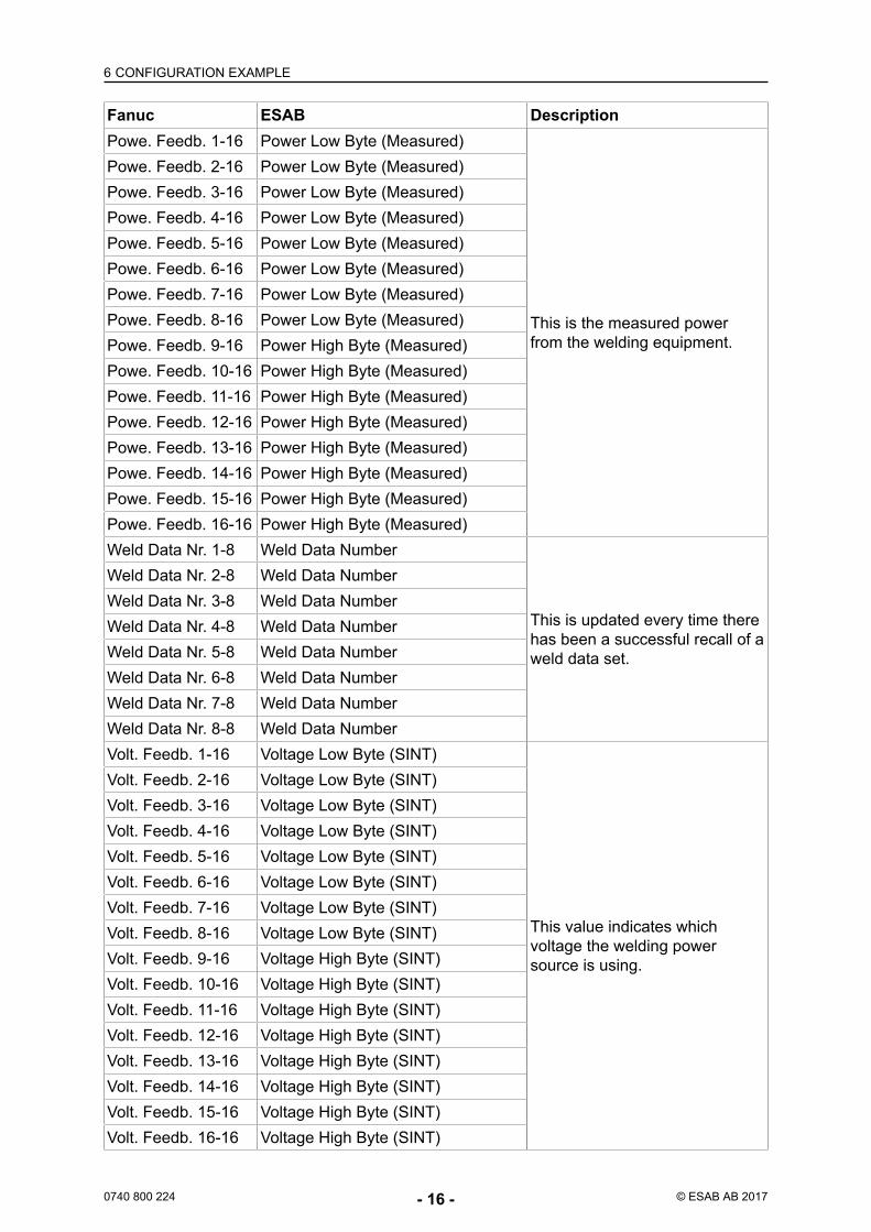
Fanuc ESAB DescriptionPowe. Feedb. 1-16 Power Low Byte (Measured)
This is the measured powerfrom the welding equipment.
Powe. Feedb. 2-16 Power Low Byte (Measured)Powe. Feedb. 3-16 Power Low Byte (Measured)Powe. Feedb. 4-16 Power Low Byte (Measured)Powe. Feedb. 5-16 Power Low Byte (Measured)Powe. Feedb. 6-16 Power Low Byte (Measured)Powe. Feedb. 7-16 Power Low Byte (Measured)Powe. Feedb. 8-16 Power Low Byte (Measured)Powe. Feedb. 9-16 Power High Byte (Measured)Powe. Feedb. 10-16 Power High Byte (Measured)Powe. Feedb. 11-16 Power High Byte (Measured)Powe. Feedb. 12-16 Power High Byte (Measured)Powe. Feedb. 13-16 Power High Byte (Measured)Powe. Feedb. 14-16 Power High Byte (Measured)Powe. Feedb. 15-16 Power High Byte (Measured)Powe. Feedb. 16-16 Power High Byte (Measured)Weld Data Nr. 1-8 Weld Data Number
This is updated every time therehas been a successful recall of aweld data set.
Weld Data Nr. 2-8 Weld Data NumberWeld Data Nr. 3-8 Weld Data NumberWeld Data Nr. 4-8 Weld Data NumberWeld Data Nr. 5-8 Weld Data NumberWeld Data Nr. 6-8 Weld Data NumberWeld Data Nr. 7-8 Weld Data NumberWeld Data Nr. 8-8 Weld Data NumberVolt. Feedb. 1-16 Voltage Low Byte (SINT)
This value indicates whichvoltage the welding powersource is using.
Volt. Feedb. 2-16 Voltage Low Byte (SINT)Volt. Feedb. 3-16 Voltage Low Byte (SINT)Volt. Feedb. 4-16 Voltage Low Byte (SINT)Volt. Feedb. 5-16 Voltage Low Byte (SINT)Volt. Feedb. 6-16 Voltage Low Byte (SINT)Volt. Feedb. 7-16 Voltage Low Byte (SINT)Volt. Feedb. 8-16 Voltage Low Byte (SINT)Volt. Feedb. 9-16 Voltage High Byte (SINT)Volt. Feedb. 10-16 Voltage High Byte (SINT)Volt. Feedb. 11-16 Voltage High Byte (SINT)Volt. Feedb. 12-16 Voltage High Byte (SINT)Volt. Feedb. 13-16 Voltage High Byte (SINT)Volt. Feedb. 14-16 Voltage High Byte (SINT)Volt. Feedb. 15-16 Voltage High Byte (SINT)Volt. Feedb. 16-16 Voltage High Byte (SINT)
6 CONFIGURATION EXAMPLE
0740 800 224 - 17 - © ESAB AB 2017
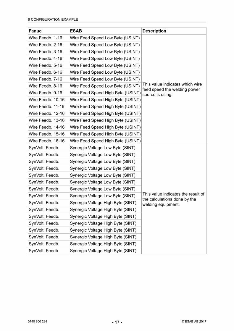
Fanuc ESAB DescriptionWire Feedb. 1-16 Wire Feed Speed Low Byte (USINT)
This value indicates which wirefeed speed the welding powersource is using.
Wire Feedb. 2-16 Wire Feed Speed Low Byte (USINT)Wire Feedb. 3-16 Wire Feed Speed Low Byte (USINT)Wire Feedb. 4-16 Wire Feed Speed Low Byte (USINT)Wire Feedb. 5-16 Wire Feed Speed Low Byte (USINT)Wire Feedb. 6-16 Wire Feed Speed Low Byte (USINT)Wire Feedb. 7-16 Wire Feed Speed Low Byte (USINT)Wire Feedb. 8-16 Wire Feed Speed Low Byte (USINT)Wire Feedb. 9-16 Wire Feed Speed High Byte (USINT)Wire Feedb. 10-16 Wire Feed Speed High Byte (USINT)Wire Feedb. 11-16 Wire Feed Speed High Byte (USINT)Wire Feedb. 12-16 Wire Feed Speed High Byte (USINT)Wire Feedb. 13-16 Wire Feed Speed High Byte (USINT)Wire Feedb. 14-16 Wire Feed Speed High Byte (USINT)Wire Feedb. 15-16 Wire Feed Speed High Byte (USINT)Wire Feedb. 16-16 Wire Feed Speed High Byte (USINT)SynVolt. Feedb. Synergic Voltage Low Byte (SINT)
This value indicates the result ofthe calculations done by thewelding equipment.
SynVolt. Feedb. Synergic Voltage Low Byte (SINT)SynVolt. Feedb. Synergic Voltage Low Byte (SINT)SynVolt. Feedb. Synergic Voltage Low Byte (SINT)SynVolt. Feedb. Synergic Voltage Low Byte (SINT)SynVolt. Feedb. Synergic Voltage Low Byte (SINT)SynVolt. Feedb. Synergic Voltage Low Byte (SINT)SynVolt. Feedb. Synergic Voltage Low Byte (SINT)SynVolt. Feedb. Synergic Voltage High Byte (SINT)SynVolt. Feedb. Synergic Voltage High Byte (SINT)SynVolt. Feedb. Synergic Voltage High Byte (SINT)SynVolt. Feedb. Synergic Voltage High Byte (SINT)SynVolt. Feedb. Synergic Voltage High Byte (SINT)SynVolt. Feedb. Synergic Voltage High Byte (SINT)SynVolt. Feedb. Synergic Voltage High Byte (SINT)SynVolt. Feedb. Synergic Voltage High Byte (SINT)
6 CONFIGURATION EXAMPLE
0740 800 224 - 18 - © ESAB AB 2017
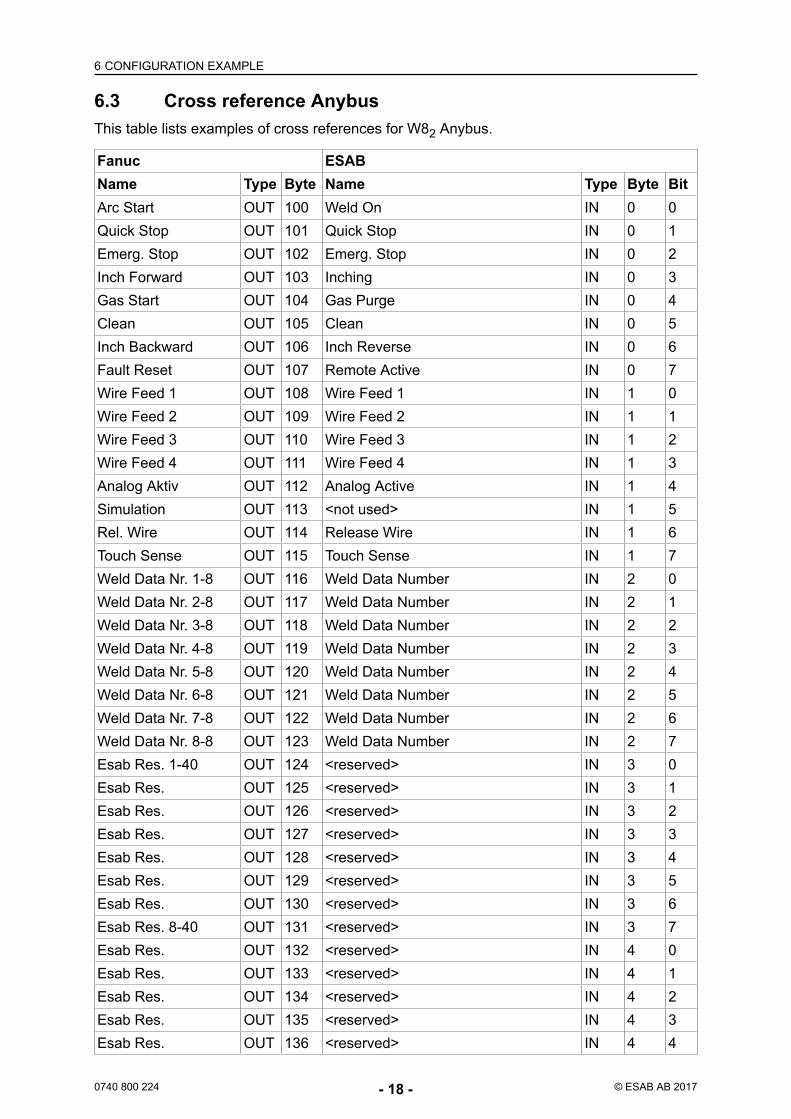
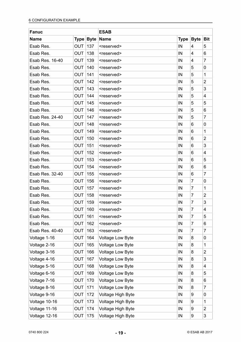
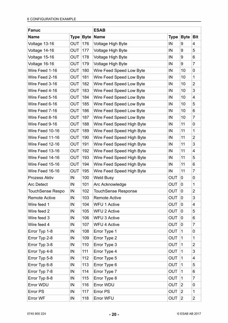
6.3 Cross reference AnybusThis table lists examples of cross references for W82 Anybus.
Fanuc ESABName Type Byte Name Type Byte BitArc Start OUT 100 Weld On IN 0 0Quick Stop OUT 101 Quick Stop IN 0 1Emerg. Stop OUT 102 Emerg. Stop IN 0 2Inch Forward OUT 103 Inching IN 0 3Gas Start OUT 104 Gas Purge IN 0 4Clean OUT 105 Clean IN 0 5Inch Backward OUT 106 Inch Reverse IN 0 6Fault Reset OUT 107 Remote Active IN 0 7Wire Feed 1 OUT 108 Wire Feed 1 IN 1 0Wire Feed 2 OUT 109 Wire Feed 2 IN 1 1Wire Feed 3 OUT 110 Wire Feed 3 IN 1 2Wire Feed 4 OUT 111 Wire Feed 4 IN 1 3Analog Aktiv OUT 112 Analog Active IN 1 4Simulation OUT 113 <not used> IN 1 5Rel. Wire OUT 114 Release Wire IN 1 6Touch Sense OUT 115 Touch Sense IN 1 7Weld Data Nr. 1-8 OUT 116 Weld Data Number IN 2 0Weld Data Nr. 2-8 OUT 117 Weld Data Number IN 2 1Weld Data Nr. 3-8 OUT 118 Weld Data Number IN 2 2Weld Data Nr. 4-8 OUT 119 Weld Data Number IN 2 3Weld Data Nr. 5-8 OUT 120 Weld Data Number IN 2 4Weld Data Nr. 6-8 OUT 121 Weld Data Number IN 2 5Weld Data Nr. 7-8 OUT 122 Weld Data Number IN 2 6Weld Data Nr. 8-8 OUT 123 Weld Data Number IN 2 7Esab Res. 1-40 OUT 124 <reserved> IN 3 0Esab Res. OUT 125 <reserved> IN 3 1Esab Res. OUT 126 <reserved> IN 3 2Esab Res. OUT 127 <reserved> IN 3 3Esab Res. OUT 128 <reserved> IN 3 4Esab Res. OUT 129 <reserved> IN 3 5Esab Res. OUT 130 <reserved> IN 3 6Esab Res. 8-40 OUT 131 <reserved> IN 3 7Esab Res. OUT 132 <reserved> IN 4 0Esab Res. OUT 133 <reserved> IN 4 1Esab Res. OUT 134 <reserved> IN 4 2Esab Res. OUT 135 <reserved> IN 4 3Esab Res. OUT 136 <reserved> IN 4 4
6 CONFIGURATION EXAMPLE
0740 800 224 - 19 - © ESAB AB 2017
Fanuc ESABName Type Byte Name Type Byte BitEsab Res. OUT 137 <reserved> IN 4 5Esab Res. OUT 138 <reserved> IN 4 6Esab Res. 16-40 OUT 139 <reserved> IN 4 7Esab Res. OUT 140 <reserved> IN 5 0Esab Res. OUT 141 <reserved> IN 5 1Esab Res. OUT 142 <reserved> IN 5 2Esab Res. OUT 143 <reserved> IN 5 3Esab Res. OUT 144 <reserved> IN 5 4Esab Res. OUT 145 <reserved> IN 5 5Esab Res. OUT 146 <reserved> IN 5 6Esab Res. 24-40 OUT 147 <reserved> IN 5 7Esab Res. OUT 148 <reserved> IN 6 0Esab Res. OUT 149 <reserved> IN 6 1Esab Res. OUT 150 <reserved> IN 6 2Esab Res. OUT 151 <reserved> IN 6 3Esab Res. OUT 152 <reserved> IN 6 4Esab Res. OUT 153 <reserved> IN 6 5Esab Res. OUT 154 <reserved> IN 6 6Esab Res. 32-40 OUT 155 <reserved> IN 6 7Esab Res. OUT 156 <reserved> IN 7 0Esab Res. OUT 157 <reserved> IN 7 1Esab Res. OUT 158 <reserved> IN 7 2Esab Res. OUT 159 <reserved> IN 7 3Esab Res. OUT 160 <reserved> IN 7 4Esab Res. OUT 161 <reserved> IN 7 5Esab Res. OUT 162 <reserved> IN 7 6Esab Res. 40-40 OUT 163 <reserved> IN 7 7Voltage 1-16 OUT 164 Voltage Low Byte IN 8 0Voltage 2-16 OUT 165 Voltage Low Byte IN 8 1Voltage 3-16 OUT 166 Voltage Low Byte IN 8 2Voltage 4-16 OUT 167 Voltage Low Byte IN 8 3Voltage 5-16 OUT 168 Voltage Low Byte IN 8 4Voltage 6-16 OUT 169 Voltage Low Byte IN 8 5Voltage 7-16 OUT 170 Voltage Low Byte IN 8 6Voltage 8-16 OUT 171 Voltage Low Byte IN 8 7Voltage 9-16 OUT 172 Voltage High Byte IN 9 0Voltage 10-16 OUT 173 Voltage High Byte IN 9 1Voltage 11-16 OUT 174 Voltage High Byte IN 9 2Voltage 12-16 OUT 175 Voltage High Byte IN 9 3
6 CONFIGURATION EXAMPLE
0740 800 224 - 20 - © ESAB AB 2017
Fanuc ESABName Type Byte Name Type Byte BitVoltage 13-16 OUT 176 Voltage High Byte IN 9 4Voltage 14-16 OUT 177 Voltage High Byte IN 9 5Voltage 15-16 OUT 178 Voltage High Byte IN 9 6Voltage 16-16 OUT 179 Voltage High Byte IN 9 7Wire Feed 1-16 OUT 180 Wire Feed Speed Low Byte IN 10 0Wire Feed 2-16 OUT 181 Wire Feed Speed Low Byte IN 10 1Wire Feed 3-16 OUT 182 Wire Feed Speed Low Byte IN 10 2Wire Feed 4-16 OUT 183 Wire Feed Speed Low Byte IN 10 3Wire Feed 5-16 OUT 184 Wire Feed Speed Low Byte IN 10 4Wire Feed 6-16 OUT 185 Wire Feed Speed Low Byte IN 10 5Wire Feed 7-16 OUT 186 Wire Feed Speed Low Byte IN 10 6Wire Feed 8-16 OUT 187 Wire Feed Speed Low Byte IN 10 7Wire Feed 9-16 OUT 188 Wire Feed Speed High Byte IN 11 0Wire Feed 10-16 OUT 189 Wire Feed Speed High Byte IN 11 1Wire Feed 11-16 OUT 190 Wire Feed Speed High Byte IN 11 2Wire Feed 12-16 OUT 191 Wire Feed Speed High Byte IN 11 3Wire Feed 13-16 OUT 192 Wire Feed Speed High Byte IN 11 4Wire Feed 14-16 OUT 193 Wire Feed Speed High Byte IN 11 5Wire Feed 15-16 OUT 194 Wire Feed Speed High Byte IN 11 6Wire Feed 16-16 OUT 195 Wire Feed Speed High Byte IN 11 7Prozess Aktiv IN 100 Weld Busy OUT 0 0Arc Detect IN 101 Arc Acknowledge OUT 0 1TouchSense Respo IN 102 TouchSense Response OUT 0 2Remote Active IN 103 Remote Active OUT 0 3Wire feed 1 IN 104 WFU 1 Active OUT 0 4Wire feed 2 IN 105 WFU 2 Active OUT 0 5Wire feed 3 IN 106 WFU 3 Active OUT 0 6Wire feed 4 IN 107 WFU 4 Active OUT 0 7Error Typ 1-8 IN 108 Error Type 1 OUT 1 0Error Typ 2-8 IN 109 Error Type 2 OUT 1 1Error Typ 3-8 IN 110 Error Type 3 OUT 1 2Error Typ 4-8 IN 111 Error Type 4 OUT 1 3Error Typ 5-8 IN 112 Error Type 5 OUT 1 4Error Typ 6-8 IN 113 Error Type 6 OUT 1 5Error Typ 7-8 IN 114 Error Type 7 OUT 1 6Error Typ 8-8 IN 115 Error Type 8 OUT 1 7Error WDU IN 116 Error WDU OUT 2 0Error PS IN 117 Error PS OUT 2 1Error WF IN 118 Error WFU OUT 2 2
6 CONFIGURATION EXAMPLE
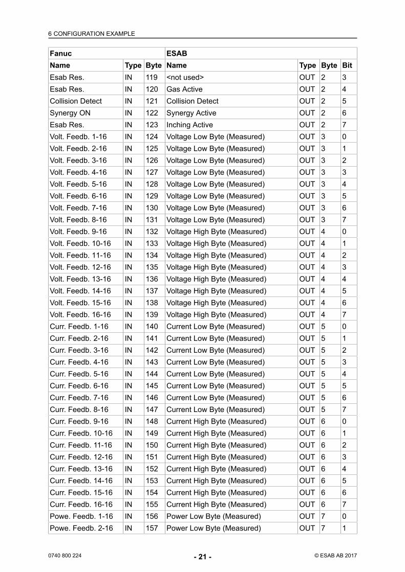
0740 800 224 - 21 - © ESAB AB 2017
Fanuc ESABName Type Byte Name Type Byte BitEsab Res. IN 119 <not used> OUT 2 3Esab Res. IN 120 Gas Active OUT 2 4Collision Detect IN 121 Collision Detect OUT 2 5Synergy ON IN 122 Synergy Active OUT 2 6Esab Res. IN 123 Inching Active OUT 2 7Volt. Feedb. 1-16 IN 124 Voltage Low Byte (Measured) OUT 3 0Volt. Feedb. 2-16 IN 125 Voltage Low Byte (Measured) OUT 3 1Volt. Feedb. 3-16 IN 126 Voltage Low Byte (Measured) OUT 3 2Volt. Feedb. 4-16 IN 127 Voltage Low Byte (Measured) OUT 3 3Volt. Feedb. 5-16 IN 128 Voltage Low Byte (Measured) OUT 3 4Volt. Feedb. 6-16 IN 129 Voltage Low Byte (Measured) OUT 3 5Volt. Feedb. 7-16 IN 130 Voltage Low Byte (Measured) OUT 3 6Volt. Feedb. 8-16 IN 131 Voltage Low Byte (Measured) OUT 3 7Volt. Feedb. 9-16 IN 132 Voltage High Byte (Measured) OUT 4 0Volt. Feedb. 10-16 IN 133 Voltage High Byte (Measured) OUT 4 1Volt. Feedb. 11-16 IN 134 Voltage High Byte (Measured) OUT 4 2Volt. Feedb. 12-16 IN 135 Voltage High Byte (Measured) OUT 4 3Volt. Feedb. 13-16 IN 136 Voltage High Byte (Measured) OUT 4 4Volt. Feedb. 14-16 IN 137 Voltage High Byte (Measured) OUT 4 5Volt. Feedb. 15-16 IN 138 Voltage High Byte (Measured) OUT 4 6Volt. Feedb. 16-16 IN 139 Voltage High Byte (Measured) OUT 4 7Curr. Feedb. 1-16 IN 140 Current Low Byte (Measured) OUT 5 0Curr. Feedb. 2-16 IN 141 Current Low Byte (Measured) OUT 5 1Curr. Feedb. 3-16 IN 142 Current Low Byte (Measured) OUT 5 2Curr. Feedb. 4-16 IN 143 Current Low Byte (Measured) OUT 5 3Curr. Feedb. 5-16 IN 144 Current Low Byte (Measured) OUT 5 4Curr. Feedb. 6-16 IN 145 Current Low Byte (Measured) OUT 5 5Curr. Feedb. 7-16 IN 146 Current Low Byte (Measured) OUT 5 6Curr. Feedb. 8-16 IN 147 Current Low Byte (Measured) OUT 5 7Curr. Feedb. 9-16 IN 148 Current High Byte (Measured) OUT 6 0Curr. Feedb. 10-16 IN 149 Current High Byte (Measured) OUT 6 1Curr. Feedb. 11-16 IN 150 Current High Byte (Measured) OUT 6 2Curr. Feedb. 12-16 IN 151 Current High Byte (Measured) OUT 6 3Curr. Feedb. 13-16 IN 152 Current High Byte (Measured) OUT 6 4Curr. Feedb. 14-16 IN 153 Current High Byte (Measured) OUT 6 5Curr. Feedb. 15-16 IN 154 Current High Byte (Measured) OUT 6 6Curr. Feedb. 16-16 IN 155 Current High Byte (Measured) OUT 6 7Powe. Feedb. 1-16 IN 156 Power Low Byte (Measured) OUT 7 0Powe. Feedb. 2-16 IN 157 Power Low Byte (Measured) OUT 7 1
6 CONFIGURATION EXAMPLE
0740 800 224 - 22 - © ESAB AB 2017
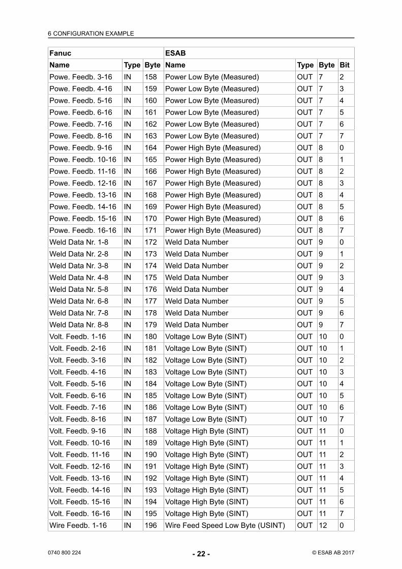
Fanuc ESABName Type Byte Name Type Byte BitPowe. Feedb. 3-16 IN 158 Power Low Byte (Measured) OUT 7 2Powe. Feedb. 4-16 IN 159 Power Low Byte (Measured) OUT 7 3Powe. Feedb. 5-16 IN 160 Power Low Byte (Measured) OUT 7 4Powe. Feedb. 6-16 IN 161 Power Low Byte (Measured) OUT 7 5Powe. Feedb. 7-16 IN 162 Power Low Byte (Measured) OUT 7 6Powe. Feedb. 8-16 IN 163 Power Low Byte (Measured) OUT 7 7Powe. Feedb. 9-16 IN 164 Power High Byte (Measured) OUT 8 0Powe. Feedb. 10-16 IN 165 Power High Byte (Measured) OUT 8 1Powe. Feedb. 11-16 IN 166 Power High Byte (Measured) OUT 8 2Powe. Feedb. 12-16 IN 167 Power High Byte (Measured) OUT 8 3Powe. Feedb. 13-16 IN 168 Power High Byte (Measured) OUT 8 4Powe. Feedb. 14-16 IN 169 Power High Byte (Measured) OUT 8 5Powe. Feedb. 15-16 IN 170 Power High Byte (Measured) OUT 8 6Powe. Feedb. 16-16 IN 171 Power High Byte (Measured) OUT 8 7Weld Data Nr. 1-8 IN 172 Weld Data Number OUT 9 0Weld Data Nr. 2-8 IN 173 Weld Data Number OUT 9 1Weld Data Nr. 3-8 IN 174 Weld Data Number OUT 9 2Weld Data Nr. 4-8 IN 175 Weld Data Number OUT 9 3Weld Data Nr. 5-8 IN 176 Weld Data Number OUT 9 4Weld Data Nr. 6-8 IN 177 Weld Data Number OUT 9 5Weld Data Nr. 7-8 IN 178 Weld Data Number OUT 9 6Weld Data Nr. 8-8 IN 179 Weld Data Number OUT 9 7Volt. Feedb. 1-16 IN 180 Voltage Low Byte (SINT) OUT 10 0Volt. Feedb. 2-16 IN 181 Voltage Low Byte (SINT) OUT 10 1Volt. Feedb. 3-16 IN 182 Voltage Low Byte (SINT) OUT 10 2Volt. Feedb. 4-16 IN 183 Voltage Low Byte (SINT) OUT 10 3Volt. Feedb. 5-16 IN 184 Voltage Low Byte (SINT) OUT 10 4Volt. Feedb. 6-16 IN 185 Voltage Low Byte (SINT) OUT 10 5Volt. Feedb. 7-16 IN 186 Voltage Low Byte (SINT) OUT 10 6Volt. Feedb. 8-16 IN 187 Voltage Low Byte (SINT) OUT 10 7Volt. Feedb. 9-16 IN 188 Voltage High Byte (SINT) OUT 11 0Volt. Feedb. 10-16 IN 189 Voltage High Byte (SINT) OUT 11 1Volt. Feedb. 11-16 IN 190 Voltage High Byte (SINT) OUT 11 2Volt. Feedb. 12-16 IN 191 Voltage High Byte (SINT) OUT 11 3Volt. Feedb. 13-16 IN 192 Voltage High Byte (SINT) OUT 11 4Volt. Feedb. 14-16 IN 193 Voltage High Byte (SINT) OUT 11 5Volt. Feedb. 15-16 IN 194 Voltage High Byte (SINT) OUT 11 6Volt. Feedb. 16-16 IN 195 Voltage High Byte (SINT) OUT 11 7Wire Feedb. 1-16 IN 196 Wire Feed Speed Low Byte (USINT) OUT 12 0
6 CONFIGURATION EXAMPLE
0740 800 224 - 23 - © ESAB AB 2017
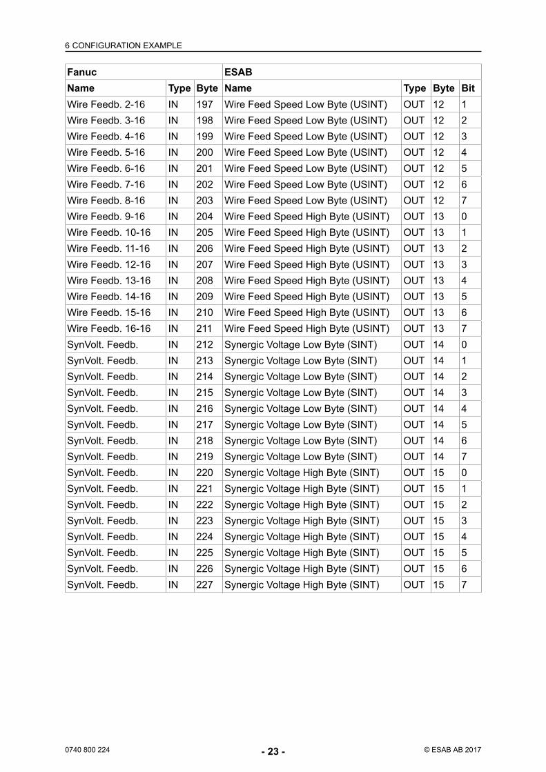
Fanuc ESABName Type Byte Name Type Byte BitWire Feedb. 2-16 IN 197 Wire Feed Speed Low Byte (USINT) OUT 12 1Wire Feedb. 3-16 IN 198 Wire Feed Speed Low Byte (USINT) OUT 12 2Wire Feedb. 4-16 IN 199 Wire Feed Speed Low Byte (USINT) OUT 12 3Wire Feedb. 5-16 IN 200 Wire Feed Speed Low Byte (USINT) OUT 12 4Wire Feedb. 6-16 IN 201 Wire Feed Speed Low Byte (USINT) OUT 12 5Wire Feedb. 7-16 IN 202 Wire Feed Speed Low Byte (USINT) OUT 12 6Wire Feedb. 8-16 IN 203 Wire Feed Speed Low Byte (USINT) OUT 12 7Wire Feedb. 9-16 IN 204 Wire Feed Speed High Byte (USINT) OUT 13 0Wire Feedb. 10-16 IN 205 Wire Feed Speed High Byte (USINT) OUT 13 1Wire Feedb. 11-16 IN 206 Wire Feed Speed High Byte (USINT) OUT 13 2Wire Feedb. 12-16 IN 207 Wire Feed Speed High Byte (USINT) OUT 13 3Wire Feedb. 13-16 IN 208 Wire Feed Speed High Byte (USINT) OUT 13 4Wire Feedb. 14-16 IN 209 Wire Feed Speed High Byte (USINT) OUT 13 5Wire Feedb. 15-16 IN 210 Wire Feed Speed High Byte (USINT) OUT 13 6Wire Feedb. 16-16 IN 211 Wire Feed Speed High Byte (USINT) OUT 13 7SynVolt. Feedb. IN 212 Synergic Voltage Low Byte (SINT) OUT 14 0SynVolt. Feedb. IN 213 Synergic Voltage Low Byte (SINT) OUT 14 1SynVolt. Feedb. IN 214 Synergic Voltage Low Byte (SINT) OUT 14 2SynVolt. Feedb. IN 215 Synergic Voltage Low Byte (SINT) OUT 14 3SynVolt. Feedb. IN 216 Synergic Voltage Low Byte (SINT) OUT 14 4SynVolt. Feedb. IN 217 Synergic Voltage Low Byte (SINT) OUT 14 5SynVolt. Feedb. IN 218 Synergic Voltage Low Byte (SINT) OUT 14 6SynVolt. Feedb. IN 219 Synergic Voltage Low Byte (SINT) OUT 14 7SynVolt. Feedb. IN 220 Synergic Voltage High Byte (SINT) OUT 15 0SynVolt. Feedb. IN 221 Synergic Voltage High Byte (SINT) OUT 15 1SynVolt. Feedb. IN 222 Synergic Voltage High Byte (SINT) OUT 15 2SynVolt. Feedb. IN 223 Synergic Voltage High Byte (SINT) OUT 15 3SynVolt. Feedb. IN 224 Synergic Voltage High Byte (SINT) OUT 15 4SynVolt. Feedb. IN 225 Synergic Voltage High Byte (SINT) OUT 15 5SynVolt. Feedb. IN 226 Synergic Voltage High Byte (SINT) OUT 15 6SynVolt. Feedb. IN 227 Synergic Voltage High Byte (SINT) OUT 15 7
7 FUNCTIONAL DESCRIPTION OF I/O
0740 800 224 - 24 - © ESAB AB 2017
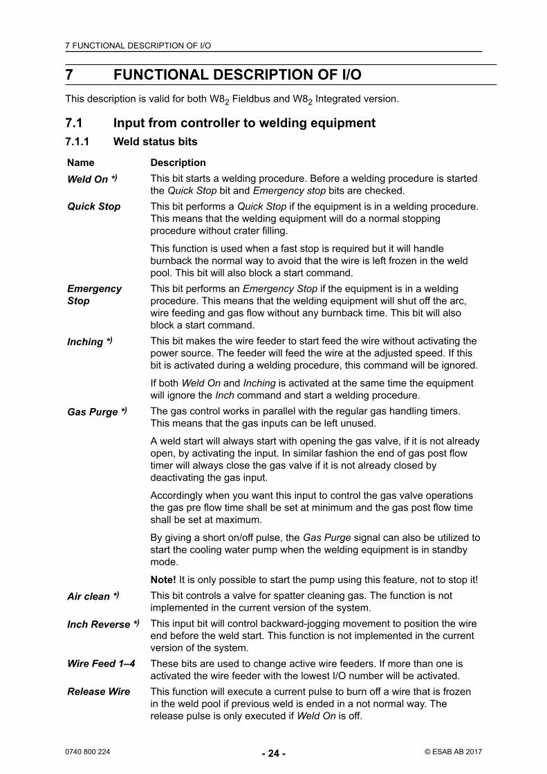
7 FUNCTIONAL DESCRIPTION OF I/OThis description is valid for both W82 Fieldbus and W82 Integrated version.
7.1 Input from controller to welding equipment7.1.1 Weld status bits
Name DescriptionWeld On *) This bit starts a welding procedure. Before a welding procedure is started
the Quick Stop bit and Emergency stop bits are checked.Quick Stop This bit performs a Quick Stop if the equipment is in a welding procedure.
This means that the welding equipment will do a normal stoppingprocedure without crater filling.
This function is used when a fast stop is required but it will handleburnback the normal way to avoid that the wire is left frozen in the weldpool. This bit will also block a start command.
EmergencyStop
This bit performs an Emergency Stop if the equipment is in a weldingprocedure. This means that the welding equipment will shut off the arc,wire feeding and gas flow without any burnback time. This bit will alsoblock a start command.
Inching *) This bit makes the wire feeder to start feed the wire without activating thepower source. The feeder will feed the wire at the adjusted speed. If thisbit is activated during a welding procedure, this command will be ignored.
If both Weld On and Inching is activated at the same time the equipmentwill ignore the Inch command and start a welding procedure.
Gas Purge *) The gas control works in parallel with the regular gas handling timers.This means that the gas inputs can be left unused.
A weld start will always start with opening the gas valve, if it is not alreadyopen, by activating the input. In similar fashion the end of gas post flowtimer will always close the gas valve if it is not already closed bydeactivating the gas input.
Accordingly when you want this input to control the gas valve operationsthe gas pre flow time shall be set at minimum and the gas post flow timeshall be set at maximum.
By giving a short on/off pulse, the Gas Purge signal can also be utilized tostart the cooling water pump when the welding equipment is in standbymode.
Note! It is only possible to start the pump using this feature, not to stop it!Air clean *) This bit controls a valve for spatter cleaning gas. The function is not
implemented in the current version of the system.Inch Reverse *) This input bit will control backward-jogging movement to position the wire
end before the weld start. This function is not implemented in the currentversion of the system.
Wire Feed 1–4 These bits are used to change active wire feeders. If more than one isactivated the wire feeder with the lowest I/O number will be activated.
Release Wire This function will execute a current pulse to burn off a wire that is frozenin the weld pool if previous weld is ended in a not normal way. Therelease pulse is only executed if Weld On is off.
7 FUNCTIONAL DESCRIPTION OF I/O
0740 800 224 - 25 - © ESAB AB 2017
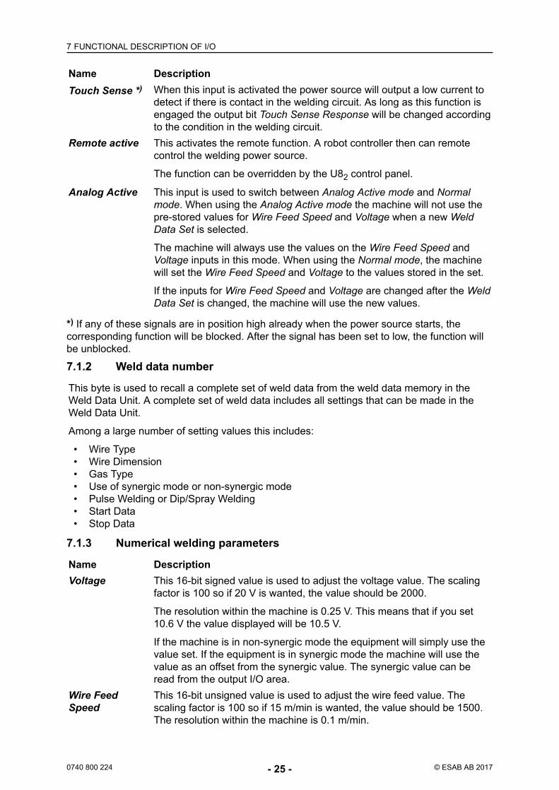
Name DescriptionTouch Sense *) When this input is activated the power source will output a low current to
detect if there is contact in the welding circuit. As long as this function isengaged the output bit Touch Sense Response will be changed accordingto the condition in the welding circuit.
Remote active This activates the remote function. A robot controller then can remotecontrol the welding power source.
The function can be overridden by the U82 control panel.
Analog Active This input is used to switch between Analog Active mode and Normalmode. When using the Analog Active mode the machine will not use thepre-stored values for Wire Feed Speed and Voltage when a new WeldData Set is selected.
The machine will always use the values on the Wire Feed Speed andVoltage inputs in this mode. When using the Normal mode, the machinewill set the Wire Feed Speed and Voltage to the values stored in the set.
If the inputs for Wire Feed Speed and Voltage are changed after the WeldData Set is changed, the machine will use the new values.
*) If any of these signals are in position high already when the power source starts, thecorresponding function will be blocked. After the signal has been set to low, the function willbe unblocked.
7.1.2 Weld data number
This byte is used to recall a complete set of weld data from the weld data memory in theWeld Data Unit. A complete set of weld data includes all settings that can be made in theWeld Data Unit.
Among a large number of setting values this includes:
• Wire Type• Wire Dimension• Gas Type• Use of synergic mode or non-synergic mode• Pulse Welding or Dip/Spray Welding• Start Data• Stop Data
7.1.3 Numerical welding parameters
Name DescriptionVoltage This 16-bit signed value is used to adjust the voltage value. The scaling
factor is 100 so if 20 V is wanted, the value should be 2000.
The resolution within the machine is 0.25 V. This means that if you set10.6 V the value displayed will be 10.5 V.
If the machine is in non-synergic mode the equipment will simply use thevalue set. If the equipment is in synergic mode the machine will use thevalue as an offset from the synergic value. The synergic value can beread from the output I/O area.
Wire FeedSpeed
This 16-bit unsigned value is used to adjust the wire feed value. Thescaling factor is 100 so if 15 m/min is wanted, the value should be 1500.The resolution within the machine is 0.1 m/min.
7 FUNCTIONAL DESCRIPTION OF I/O
0740 800 224 - 26 - © ESAB AB 2017
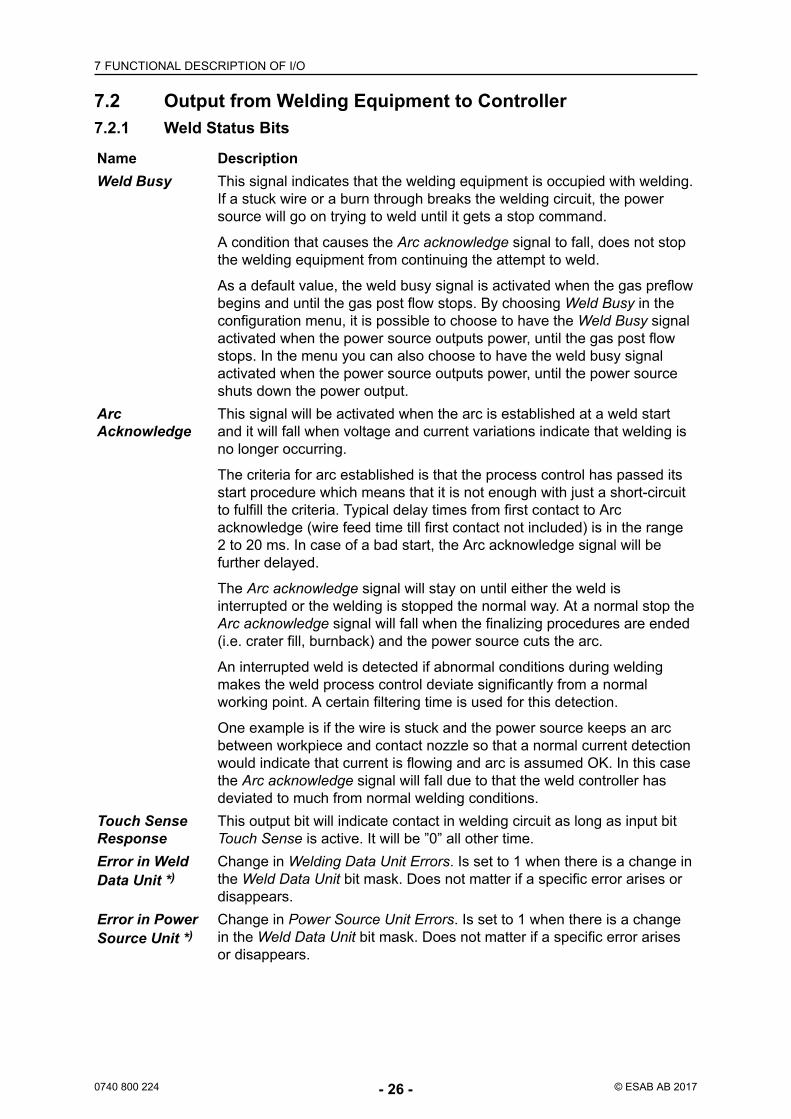
7.2 Output from Welding Equipment to Controller7.2.1 Weld Status Bits
Name DescriptionWeld Busy This signal indicates that the welding equipment is occupied with welding.
If a stuck wire or a burn through breaks the welding circuit, the powersource will go on trying to weld until it gets a stop command.
A condition that causes the Arc acknowledge signal to fall, does not stopthe welding equipment from continuing the attempt to weld.
As a default value, the weld busy signal is activated when the gas preflowbegins and until the gas post flow stops. By choosing Weld Busy in theconfiguration menu, it is possible to choose to have the Weld Busy signalactivated when the power source outputs power, until the gas post flowstops. In the menu you can also choose to have the weld busy signalactivated when the power source outputs power, until the power sourceshuts down the power output.
ArcAcknowledge
This signal will be activated when the arc is established at a weld startand it will fall when voltage and current variations indicate that welding isno longer occurring.
The criteria for arc established is that the process control has passed itsstart procedure which means that it is not enough with just a short-circuitto fulfill the criteria. Typical delay times from first contact to Arcacknowledge (wire feed time till first contact not included) is in the range2 to 20 ms. In case of a bad start, the Arc acknowledge signal will befurther delayed.
The Arc acknowledge signal will stay on until either the weld isinterrupted or the welding is stopped the normal way. At a normal stop theArc acknowledge signal will fall when the finalizing procedures are ended(i.e. crater fill, burnback) and the power source cuts the arc.
An interrupted weld is detected if abnormal conditions during weldingmakes the weld process control deviate significantly from a normalworking point. A certain filtering time is used for this detection.
One example is if the wire is stuck and the power source keeps an arcbetween workpiece and contact nozzle so that a normal current detectionwould indicate that current is flowing and arc is assumed OK. In this casethe Arc acknowledge signal will fall due to that the weld controller hasdeviated to much from normal welding conditions.
Touch SenseResponse
This output bit will indicate contact in welding circuit as long as input bitTouch Sense is active. It will be ”0” all other time.
Error in WeldData Unit *)
Change in Welding Data Unit Errors. Is set to 1 when there is a change inthe Weld Data Unit bit mask. Does not matter if a specific error arises ordisappears.
Error in PowerSource Unit *)
Change in Power Source Unit Errors. Is set to 1 when there is a changein the Weld Data Unit bit mask. Does not matter if a specific error arisesor disappears.
7 FUNCTIONAL DESCRIPTION OF I/O
0740 800 224 - 27 - © ESAB AB 2017
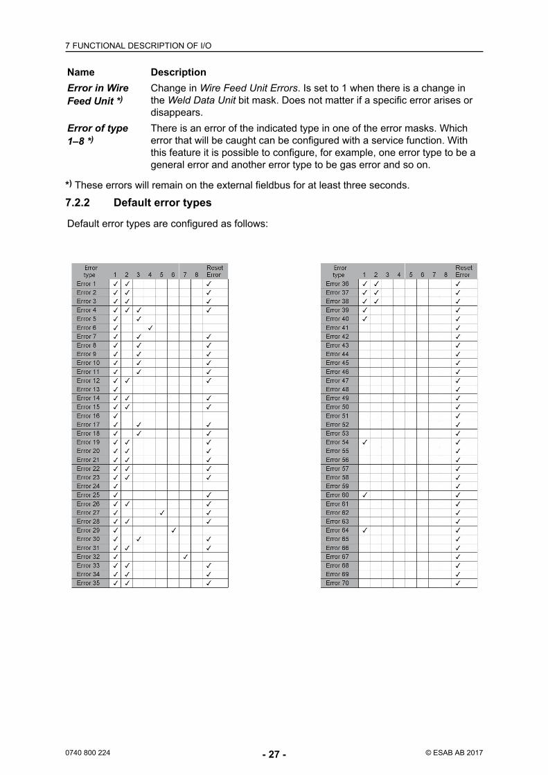
Name DescriptionError in WireFeed Unit *)
Change in Wire Feed Unit Errors. Is set to 1 when there is a change inthe Weld Data Unit bit mask. Does not matter if a specific error arises ordisappears.
Error of type1–8 *)
There is an error of the indicated type in one of the error masks. Whicherror that will be caught can be configured with a service function. Withthis feature it is possible to configure, for example, one error type to be ageneral error and another error type to be gas error and so on.
*) These errors will remain on the external fieldbus for at least three seconds.
7.2.2 Default error types
Default error types are configured as follows:
7 FUNCTIONAL DESCRIPTION OF I/O
0740 800 224 - 28 - © ESAB AB 2017
7.2.3 Weld Data Number
Name DescriptionWeld DataNumber
This byte is updated every time there has been a successful recall of aWeld Data Set. In case that the desired Weld Data Set does not exist inthe Weld Data Memory, the old number will remain.
Note that if the controller recall a Weld Data Set and the Operator usesthe Weld Data Unit to change any individual parameter, the Weld Data inthe Operating Weld Data Memory and the Weld Data in the Weld DataSet indicated by this byte will not be consistent.
7.2.4 Numerical Welding Parameters
Name DescriptionVoltage This 16-bit unsigned value indicates which voltage the welding machine
is using. If a value is set outside limits, this value will be set to the nearestallowed value.
Wire FeedSpeed
This 16-bit signed value indicates which wire feed speed the wire feederis using. If a value is set outside limits, this value will be set to the nearestallowed value.
SynergicVoltage
This 16-bit unsigned value indicates the result of the calculationsperformed by the welding equipment. The difference between this valueand the voltage is the offset. This value is only valid when running insynergic mode.
7.2.5 Measured Values
Name DescriptionVoltage This value is measured by the welding equipment. In pulse welding it can
be configured if the value presented should be the average value or thepulse value.
Current This value is measured by the welding equipment.Power This value is measured by the welding equipment.
7.2.6 Error Mask
Name DescriptionWeld Data Unit This error mask indicates which errors that are presently activated in the
Weld Data Unit.Power source This error mask indicates which errors that are presently activated in the
power source.Wire feeder This error mask indicates which errors that are presently activated in the
wire feed unit.

8 SERVICE INSTRUCTIONS
0740 800 224 - 29 - © ESAB AB 2017
8 SERVICE INSTRUCTIONS
CAUTION!STATIC ELECTRICITY can damage circuit boards andelectronic components.
• Observe precautions for handling electrostaticsensitive devices.
• Use proper static-proof bags and boxes.
8.1 What is ESD?
A sudden transfer or discharge of static electricity from one object to another. ESD standsfor Electrostatic Discharge.
How does ESD damage occur?
ESD can cause damage to sensitive electrical components, but is not dangerous to people.ESD damage occurs when an ungrounded person or object with a static charge comes intocontact with a component or assembly that is grounded. A rapid discharge can occur,causing damage. This damage can take the form of immediate failure, but it is more likelythat system performance will be affected and the component will fail prematurely.
How do we prevent ESD damage?
ESD damage can be prevented by awareness. If static electricity is prevented from buildingup on you or on anything at your work station, then there cannot be any static discharges.Nonconductive materials (e.g. fabrics), or insulators (e.g. plastics) generate and hold staticcharge, so you should not bring unnecessary nonconductive items into the work area.
It is obviously difficult to avoid all such items, so various means are used to drain off anystatic discharge from persons to prevent the risk of ESD damage. This is done by simpledevices: wrist straps, connected to ground, and conductive shoes.
Work surfaces, carts and containers must be conductive and grounded. Use only antistaticpackaging materials. Overall, handling of ESD-sensitive devices should be minimized toprevent damage.

9 SPARE PARTS
0740 800 224 - 30 - © ESAB AB 2017
9 SPARE PARTSThe spare parts list is published in a separate document that can be downloaded from theInternet: www.esab.com
Product FilenameAristo W82 0459 839 038
9.1 Ordering spare partsSpare parts and wear parts can be ordered through your nearest ESAB dealer, see the backcover of this document. When ordering, please state product type, serial number, designationand spare part number in accordance with the spare parts list. This facilitates dispatch andensures correct delivery.

9 SPARE PARTS
0740 800 224 - 31 - © ESAB AB 2017
ESAB subsidiaries and representative offices
www.esab.com
EuropeAUSTRIAESAB Ges.m.b.HVienna-LiesingTel: +43 1 888 25 11Fax: +43 1 888 25 11 85
BELGIUMS.A. ESAB N.V.Heist-op-den-BergTel: +32 15 25 79 30Fax: +32 15 25 79 44
BULGARIAESAB Kft Representative OfficeSofiaTel: +359 2 974 42 88Fax: +359 2 974 42 88
THE CZECH REPUBLICESAB VAMBERK s.r.o.VamberkTel: +420 2 819 40 885Fax: +420 2 819 40 120
DENMARKAktieselskabet ESABHerlevTel: +45 36 30 01 11Fax: +45 36 30 40 03
FINLANDESAB OyHelsinkiTel: +358 9 547 761Fax: +358 9 547 77 71
GREAT BRITAINESAB Group (UK) LtdWaltham CrossTel: +44 1992 76 85 15Fax: +44 1992 71 58 03
ESAB Automation LtdAndoverTel: +44 1264 33 22 33Fax: +44 1264 33 20 74
FRANCEESAB France S.A.Cergy PontoiseTel: +33 1 30 75 55 00Fax: +33 1 30 75 55 24
GERMANYESAB Welding & Cutting GmbHLangenfeldTel: +49 2173 3945-0Fax: +49 2173 3945-218
HUNGARYESAB KftBudapestTel: +36 1 20 44 182Fax: +36 1 20 44 186
ITALYESAB Saldatura S.p.A.Bareggio (Mi)Tel: +39 02 97 96 8.1Fax: +39 02 97 96 87 01
THE NETHERLANDSESAB Nederland B.V.AmersfoortTel: +31 33 422 35 55Fax: +31 33 422 35 44
NORWAYAS ESABLarvikTel: +47 33 12 10 00Fax: +47 33 11 52 03
POLANDESAB Sp.zo.o.KatowiceTel: +48 32 351 11 00Fax: +48 32 351 11 20
PORTUGALESAB LdaLisbonTel: +351 8 310 960Fax: +351 1 859 1277
ROMANIAESAB Romania Trading SRLBucharestTel: +40 316 900 600Fax: +40 316 900 601
RUSSIALLC ESABMoscowTel: +7 (495) 663 20 08Fax: +7 (495) 663 20 09
SLOVAKIAESAB Slovakia s.r.o.BratislavaTel: +421 7 44 88 24 26Fax: +421 7 44 88 87 41
SPAINESAB Ibérica S.A.San Fernando de Henares(MADRID)Tel: +34 91 878 3600Fax: +34 91 802 3461
SWEDENESAB Sverige ABGothenburgTel: +46 31 50 95 00Fax: +46 31 50 92 22
ESAB International ABGothenburgTel: +46 31 50 90 00Fax: +46 31 50 93 60
SWITZERLANDESAB Europe GmbHBaarTel: +41 1 741 25 25Fax: +41 1 740 30 55
UKRAINEESAB Ukraine LLCKievTel: +38 (044) 501 23 24Fax: +38 (044) 575 21 88
North and South AmericaARGENTINACONARCOBuenos AiresTel: +54 11 4 753 4039Fax: +54 11 4 753 6313
BRAZILESAB S.A.Contagem-MGTel: +55 31 2191 4333Fax: +55 31 2191 4440
CANADAESAB Group Canada Inc.Missisauga, OntarioTel: +1 905 670 0220Fax: +1 905 670 4879
MEXICOESAB Mexico S.A.MonterreyTel: +52 8 350 5959Fax: +52 8 350 7554
USAESAB Welding & CuttingProductsFlorence, SCTel: +1 843 669 4411Fax: +1 843 664 5748
Asia/PacificAUSTRALIAESAB South PacificArcherfield BC QLD 4108Tel: +61 1300 372 228Fax: +61 7 3711 2328
CHINAShanghai ESAB A/PShanghaiTel: +86 21 2326 3000Fax: +86 21 6566 6622
INDIAESAB India LtdCalcuttaTel: +91 33 478 45 17Fax: +91 33 468 18 80
INDONESIAP.T. ESABindo PratamaJakartaTel: +62 21 460 0188Fax: +62 21 461 2929
JAPANESAB JapanTokyoTel: +81 45 670 7073Fax: +81 45 670 7001
MALAYSIAESAB (Malaysia) Snd BhdUSJTel: +603 8023 7835Fax: +603 8023 0225
SINGAPOREESAB Asia/Pacific Pte LtdSingaporeTel: +65 6861 43 22Fax: +65 6861 31 95
SOUTH KOREAESAB SeAH CorporationKyungnamTel: +82 55 269 8170Fax: +82 55 289 8864
UNITED ARAB EMIRATESESAB Middle East FZEDubaiTel: +971 4 887 21 11Fax: +971 4 887 22 63
AfricaEGYPTESAB EgyptDokki-CairoTel: +20 2 390 96 69Fax: +20 2 393 32 13
SOUTH AFRICAESAB Africa Welding & CuttingLtdDurbanvill 7570 - Cape TownTel: +27 (0)21 975 8924
DistributorsFor addresses and phonenumbers to our distributors inother countries, please visit ourhome page
www.esab.com


