This equipment has been tested and found to comply with the limits for a Class A digital device, pursuant to part 15 of the FCC Rules. These limits are designed to provide reasonable protection against harmful interference in a residential installation. This equipment uses, generates, and can radiate radio frequency energy and, if not installed and used in accordance with these instructions, may cause harmful interference to radio communications. However, there is no guarantee that interference will not occur in a particular installation. If this equipment does cause harmful interference to radio or television reception, which can be determined by turning the equipment off and on, the user is encouraged to try to correct the interference by one or more of the following measures:
• Reorient or relocate the receiving antenna.
• Increase the separation between the equipment and receiver.
• Connect the equipment into an outlet on a circuit different from that to which the receiver is connected.
• Consult the dealer or an experienced radio/TV technician for help.
FCC PART 15.21
Users are cautioned that changes or modifications to the unit not expressly approved by Escort Memory Systems may void the user’s authority to operate the equipment.
Operation is subject to the following two conditions: (1) This device may not cause harmful interference, and (2) this device must accept any interference that may cause undesired operation.
This product complies with CFR (Code of Federal Regulations) Title 21 Part 15.225.
CE
This product complies with the following regulatory specifications: EN-300-330, EN-300-683, EN 60950, IEC 68-2-1, IEC 68-2-6, IEC 68-2-27 and IEC 68-2-28.
TELEC
This product has been certified under:
Regulations for Enforcement of the Radio Law Article 6, section 1, No. 1
1 : C O N T R O L L E R I N F O R M A T I O N
CHAPTER 1: CONTROLLER INFORMATION
1.1 HF-CNTL-485-02 OV E R V I E W Welcome to the Cobalt HF-CNTL-485-02 RFID Controller – Installation Guide. This document will assist you in the installation and setup of the Cobalt HF-CNTL-485-02 RFID Controller.
The Cobalt HF-CNTL-485-02 is a feature-rich, high frequency, Radio-Frequency Identification device that provides read/write RFID data transmission and control solutions to shop floor, item-level tracking and material handling applications. The controller is designed to be compact, rugged and reliable, in order to meet and exceed the requirements of the industrial automation industry.
1.1.1 Package Contents Unpack the Cobalt Controller hardware and accessories. Retain the original shipping carton and packing material in case any items need to be returned. Inspect each piece carefully, if an item appears to be damaged, notify your EMS product distributor.
The Cobalt HF RFID Controller product package contains the following components:
P A R T N U M B E R Q T Y D E S C R I P T I O N
HF-CNTL-485-02 1 Cobalt HF Series RFID Controller (-485)
17-3122 1 HF-CNTL-485-02 Installation Guide
20-1950 2 Screw (Socket Head Cap,M5 x 20mm, Hex #4, 18-8 SS)
20-3915 2 Washer (Spring Lock, M5, 18-8 SS)
69-1289 1 Wrench Tool (Hex #4, 4mm, L-key)
00-3000 1 Cobalt HF Series Configuration Tag
Table 1-1: HF-CNTL-485-02 - Package Contents
1.1.2 Power & Communications Interface
Connection Type: RS485
Communication Interface: Multi-drop (Subnet16™) Bus Architecture
Interface Connector: 5-pin, Male, M12 Connector (for power and data)
Maximum Cable Length: 300m
H F - C N T L - 4 8 5 - 0 2 I N S T A L L A T I O N G U I D E P / N : 1 7 - 3 1 2 2 R E V 0 3 ( 0 6 / 0 8 ) P A G E 3 O F 1 6
1 : C O N T R O L L E R I N F O R M A T I O N
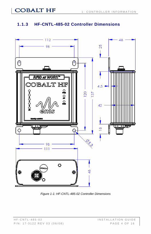
1.1.3 HF-CNTL-485-02 Controller Dimensions
Figure 1-1: HF-CNTL-485-02 Controller Dimensions
H F - C N T L - 4 8 5 - 0 2 I N S T A L L A T I O N G U I D E P / N : 1 7 - 3 1 2 2 R E V 0 3 ( 0 6 / 0 8 ) P A G E 4 O F 1 6
1 : C O N T R O L L E R I N F O R M A T I O N
1.2 CO B A L T HF-SE R I E S RFID A N T E N N A S The Cobalt HF-Series product family includes four RFID antenna models. Designed with different dimensions, each Cobalt HF-Series RFID Antenna generates a unique RF field pattern and read/write range.
Figure 1-2: Cobalt HF-Series Antennas
COBALT HF-SERIES RFID ANTENNAS – MODELS AND SIZES
ANTENNA MODEL ANTENNA SIZE
HF-ANT-1010-01 10cm x 10cm
HF-ANT-2020-01 20cm x 20cm
HF-ANT-3030-01 30cm x 30cm
HF-ANT-0750-01 7cm x 50cm
Table 1-2: Cobalt HF –Series RFID Antennas – Models and Sizes
H F - C N T L - 4 8 5 - 0 2 I N S T A L L A T I O N G U I D E P / N : 1 7 - 3 1 2 2 R E V 0 3 ( 0 6 / 0 8 ) P A G E 5 O F 1 6
1 : C O N T R O L L E R I N F O R M A T I O N
1.2.1 HF-ANT-1010-01 Antenna Dimensions
Figure 1-3: HF-ANT-1010-01 Antenna Dimensions
H F - C N T L - 4 8 5 - 0 2 I N S T A L L A T I O N G U I D E P / N : 1 7 - 3 1 2 2 R E V 0 3 ( 0 6 / 0 8 ) P A G E 6 O F 1 6
1 : C O N T R O L L E R I N F O R M A T I O N
1.2.2 HF-ANT-2020-01 Antenna Dimensions
Figure 1-4: HF-ANT-2020-01 Antenna Dimensions
H F - C N T L - 4 8 5 - 0 2 I N S T A L L A T I O N G U I D E P / N : 1 7 - 3 1 2 2 R E V 0 3 ( 0 6 / 0 8 ) P A G E 7 O F 1 6
1 : C O N T R O L L E R I N F O R M A T I O N
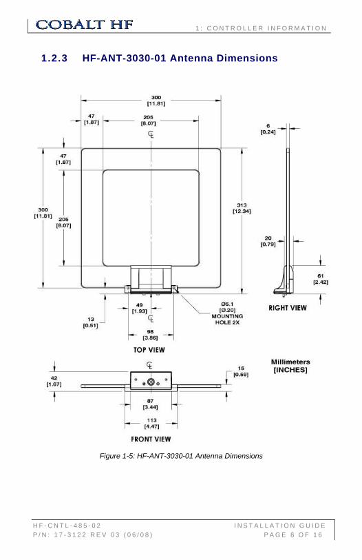
1.2.3 HF-ANT-3030-01 Antenna Dimensions
Figure 1-5: HF-ANT-3030-01 Antenna Dimensions
H F - C N T L - 4 8 5 - 0 2 I N S T A L L A T I O N G U I D E P / N : 1 7 - 3 1 2 2 R E V 0 3 ( 0 6 / 0 8 ) P A G E 8 O F 1 6
1 : C O N T R O L L E R I N F O R M A T I O N
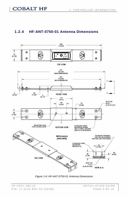
1.2.4 HF-ANT-0750-01 Antenna Dimensions
Figure 1-6: HF-ANT-0750-01 Antenna Dimensions
H F - C N T L - 4 8 5 - 0 2 I N S T A L L A T I O N G U I D E P / N : 1 7 - 3 1 2 2 R E V 0 3 ( 0 6 / 0 8 ) P A G E 9 O F 1 6
2 . C O N T R O L L E R I N S T A L L A T I O N
CHAPTER 2: CONTROLLER INSTALLATION
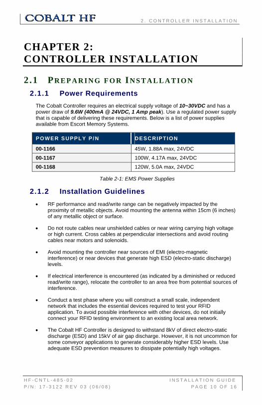
2.1 PR E P A R I N G F O R IN S T A L L A T I O N 2.1.1 Power Requirements
The Cobalt Controller requires an electrical supply voltage of 10~30VDC and has a power draw of 9.6W (400mA @ 24VDC, 1 Amp peak). Use a regulated power supply that is capable of delivering these requirements. Below is a list of power supplies available from Escort Memory Systems.
POWER SUPPLY P/N DESCRIPTION
00-1166 45W, 1.88A max, 24VDC
00-1167 100W, 4.17A max, 24VDC
00-1168 120W, 5.0A max, 24VDC
Table 2-1: EMS Power Supplies
2.1.2 Installation Guidelines • RF performance and read/write range can be negatively impacted by the
proximity of metallic objects. Avoid mounting the antenna within 15cm (6 inches) of any metallic object or surface.
• Do not route cables near unshielded cables or near wiring carrying high voltage or high current. Cross cables at perpendicular intersections and avoid routing cables near motors and solenoids.
• Avoid mounting the controller near sources of EMI (electro-magnetic interference) or near devices that generate high ESD (electro-static discharge) levels.
• If electrical interference is encountered (as indicated by a diminished or reduced read/write range), relocate the controller to an area free from potential sources of interference.
• Conduct a test phase where you will construct a small scale, independent network that includes the essential devices required to test your RFID application. To avoid possible interference with other devices, do not initially connect your RFID testing environment to an existing local area network.
• The Cobalt HF Controller is designed to withstand 8kV of direct electro-static discharge (ESD) and 15kV of air gap discharge. However, it is not uncommon for some conveyor applications to generate considerably higher ESD levels. Use adequate ESD prevention measures to dissipate potentially high voltages.
H F - C N T L - 4 8 5 - 0 2 I N S T A L L A T I O N G U I D E P / N : 1 7 - 3 1 2 2 R E V 0 3 ( 0 6 / 0 8 ) P A G E 1 0 O F 1 6
2 . C O N T R O L L E R I N S T A L L A T I O N
2.2 CO N N E C T I N G T H E AN T E N N A Cobalt HF-Series RFID Antennas mount directly to the top of the Cobalt HF-Series RFID Controller’s housing. The antenna is first attached to the RF port on the controller and is then fastened to the controller’s housing using the two M5 screws and matching spring lock washers included with each Cobalt HF-Series RFID Controller. Use the provided 4mm hex key wrench to tighten both M5 screws.
2.2.1 Torque Specification Screws should be tightened to the following torque settings:
1.7 Nm or 15 lbs / inch ± 10%
ITEM QTY DESCRIPTION
1 1 Cobalt Controller (HF-CNTL-485-02)
2 1 Cobalt Antenna (HF-ANT-1010-01)
3 2 Washer (Spring Lock, M5, 18-8 SS)
4 2 Screw (Socket Head Cap, M5 X 20mm, 18-8 SS)
H F - C N T L - 4 8 5 - 0 2 I N S T A L L A T I O N G U I D E P / N : 1 7 - 3 1 2 2 R E V 0 3 ( 0 6 / 0 8 ) P A G E 1 1 O F 1 6
2 . C O N T R O L L E R I N S T A L L A T I O N
2.2.2 Minimum Distance between Antennas When installing multiple Cobalt HF-Series Controllers/Antennas, refer to the table below to determine the recommended minimum distance to maintain between adjacent Cobalt Antennas.
C O B A L T A N T E N N A - 1 0 1 0 - 2 0 2 0 - 3 0 3 0 - 0 7 5 0
- 1 0 1 0 60cm 75cm 90cm 50cm
- 2 0 2 0 75cm 90cm 1.2m 65cm
- 3 0 3 0 90cm 1.2m 2m 90cm
- 0 7 5 0 50cm 65cm 90cm 50cm
Table 2-2: Minimum Distance between Antennas
For example, an HF-ANT-3030 RFID Antenna and an HF-ANT-1010 RFID Antenna should be located no closer than 90 centimeters apart.
2.3 IN S T A L L I N G T H E HF-CNTL-485-02 Note: review Section 2.1.2: “Installation Guidelines” prior to installing the controller.
1. Attach the Cobalt HF Antenna to the Cobalt HF Controller as per the instructions in Section 2.2: “Connecting the Antenna.”
2. Select a suitable location for the Cobalt HF Controller/Antenna. If necessary, fabricate mounting brackets from durable plastic.
3. Fasten combined controller and antenna to your mounting fixture using two M5 (#10) screws (not included). Pass screws through antenna’s mounting holes and secure them with appropriate washers and nuts. Tighten screws to 1.7 Nm or 15 lbs per inch ± 10%.
4. Connect the 5-pin, female end of an EMS approved Subnet16 cable to the controller’s 5-pin, male, M12 connector. Connect the opposite end to a Subnet16 multi-drop bus network. Note: for additional information refer to the installation guide provided with the Subnet16 Gateway or Subnet16 Hub (also available online at: www.ems-rfid.com).
5. Utilize a regulated power supply for the controller that is capable of delivering 10~30VDC, 9.6W (400mA @ 24VDC, 1 Amp peak).
6. Turn the power supply ON. The green power LED on the unit will light when power is applied to the unit.
After installation is complete, the yellow Node ID LEDs will display the currently assigned Subnet16 Node ID (in binary). Note: the Cobalt’s default Node ID is Node 00; in which case none of the yellow Node ID LEDs will be lit.
H F - C N T L - 4 8 5 - 0 2 I N S T A L L A T I O N G U I D E P / N : 1 7 - 3 1 2 2 R E V 0 3 ( 0 6 / 0 8 ) P A G E 1 2 O F 1 6
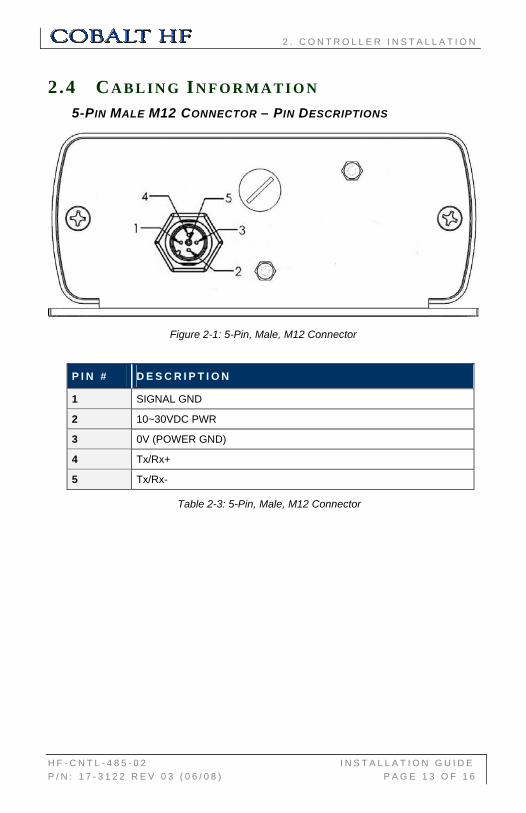
2.4 CA B L I N G IN F O R M A T I O N 5-PIN MALE M12 CONNECTOR – PIN DESCRIPTIONS
Figure 2-1: 5-Pin, Male, M12 Connector
P I N # D E S C R I P T I O N
1 SIGNAL GND
2 10~30VDC PWR
3 0V (POWER GND)
4 Tx/Rx+
5 Tx/Rx-
Table 2-3: 5-Pin, Male, M12 Connector
H F - C N T L - 4 8 5 - 0 2 I N S T A L L A T I O N G U I D E P / N : 1 7 - 3 1 2 2 R E V 0 3 ( 0 6 / 0 8 ) P A G E 1 3 O F 1 6
2 . C O N T R O L L E R I N S T A L L A T I O N
2.4.1 Optional Digital I/O Connector (*) The Cobalt HF-CNTL-232-02 may have an optional digital I/O connector to interface with external devices. This additional connector is placed in the bottom plate, on the right side of normal connectors.
8-PIN, REVERSE KEYED FEMALE DIGITAL I/O CONNECTOR
Figure 2-2: 8-Pin, Reverse Keyed Female Digital I/O Connector
P I N # D E S C R I P T I O N
1 + VDC
2 VGND
3 AUX1_OUT+
4 AUX1_OUT-
5 AUX2_OUT+
6 AUX2_OUT-
7 AUX_IN+
8 AUX_IN-
Table 2-4: 8-Pin, Reverse Keyed Female Digital I/O Connector
(*) Feature soon available in the next Cobalt HF-Series’ release with different P/N.
H F - C N T L - 4 8 5 - 0 2 I N S T A L L A T I O N G U I D E P / N : 1 7 - 3 1 2 2 R E V 0 3 ( 0 6 / 0 8 ) P A G E 1 4 O F 1 6
2 . C O N T R O L L E R I N S T A L L A T I O N
ATTENTION:
For operating instructions for the Cobalt HF-CNTL-485-02 RFID Controller, refer to the:
Cobalt HF-Series RFID Controllers – Operator’s Manual (P/N: 17-1320)
- Available online at: www.ems-rfid.com.
Also available online at www.ems-rfid.com is Escort Memory Systems’ Cobalt Dashboard™ software utility. The RFID Dashboard is a Windows-based application that provides users with complete control over their EMS RFID hardware. Users can monitor their entire RFID system - from the tag level, to the RFID controller, to the host.
H F - C N T L - 4 8 5 - 0 2 I N S T A L L A T I O N G U I D E P / N : 1 7 - 3 1 2 2 R E V 0 3 ( 0 6 / 0 8 ) P A G E 1 5 O F 1 6
Datalogic Automation warrants that all products of its own manufacturing conform to Datalogic Automation’s specifications and are free from defects in material and workmanship when used under normal operating conditions and within the service conditions for which they were furnished. The obligation of Datalogic Automation hereunder shall expire one (1) year after delivery, unless otherwise specified, and is limited to repairing, or at its option, replacing without charge, any such product, which in Datalogic Automation’s sole opinion proves to be defective within the scope of this Warranty. In the event Datalogic Automation is not able to repair or replace defective products or components within a reasonable time after receipt thereof, Buyers shall be credited for their value at the original purchase price. Datalogic Automation must be notified in writing of the defect or nonconformity within the warranty period and the affected product returned to Datalogic Automation factory or to an authorized service center within thirty (30) days after discovery of such defect or nonconformity. Shipment shall not be made without prior authorization by Datalogic Automation.
This is Datalogic Automation's sole warranty with respect to the products delivered hereunder. No statement, representation, agreement or understanding oral or written, made by an agent, distributor, representative, or employee of Datalogic Automation which is not contained in this warranty, will be binding upon Datalogic Automation, unless made in writing and executed by an authorized Datalogic Automation employee.
Datalogic Automation makes no other warranty of any kind what so ever, expressed or implied, and all implied warranties of merchantability and fitness for a particular use which exceed the aforementioned obligation are here by disclaimed by Datalogic Automation and excluded from this agreement. Under no circumstances shall Datalogic Automation be liable to Buyer, in contract or in tort, for any special, indirect, incidental, or consequential damages, expenses, losses or delay however caused. Equipment or parts that have been subjected to abuse, misuse, accident, alteration, neglect, unauthorized repair or installation are not covered by warranty. Datalogic Automation shall make the final determination as to the existence and cause of any alleged defect. No liability is assumed for expendable items such as lamps and fuses. No warranty is made with respect to equipment or products produced to Buyer’s specification except as specifically stated in writing by Datalogic Automation in the contract for such custom equipment. This warranty is the only warranty made by Datalogic Automation with respect to the goods delivered hereunder, and may be modified or amended only by a written instrument signed by a duly authorized officer of Datalogic Automation and accepted by the Buyer.
H F - C N T L - 4 8 5 - 0 2 I N S T A L L A T I O N G U I D E P / N : 1 7 - 3 1 2 2 R E V 0 3 ( 0 6 / 0 8 ) P A G E 1 6 O F 1 6