97
BIS U-62_ Processor Unit Technical Description, Manual

BIS U-62_ Processor Unit Technical Description, Manual


iii
CONTENTS
REFERENCES ........................................................................................................... 1 Conventions ................................................................................................................ 1 Reference Documentation .......................................................................................... 1 Services and Support .................................................................................................. 1
REGULATORY AND COMPLIANCE NOTICES ......................................................... 2 Power Supply .............................................................................................................. 2
GENERAL VIEW ........................................................................................................ 3
1 OVERVIEW ................................................................................................................ 1 1.1 Introduction ................................................................................................................. 1 1.2 UHF-Series Features .................................................................................................. 1 1.3 About this Manual ....................................................................................................... 1 1.3.1 Who Should Read This Manual? ................................................................................. 2 1.3.2 HEX Notation .............................................................................................................. 2 1.4 Models and Accessories ............................................................................................. 2 1.5 Balluff RFID Tags ........................................................................................................ 3
2 INSTALLATION .......................................................................................................... 1 2.1 Mechanical Dimensions .............................................................................................. 1 2.1.1 BIS U-620-068-10_-00-ST_ RS232 Models ................................................................ 1 2.1.2 BIS U-620-067-10_-04-ST_ RS485 Models ................................................................ 2 2.1.3 BIS U-626-069-10_-06-ST_ IND Models ..................................................................... 3 2.2 BIS U-30_ Antenna Mounting ...................................................................................... 5 2.2.1 Minimum Mounting Distance between Adjacent Antennas .......................................... 5 2.2.2 Antenna to Tag Range ................................................................................................ 5 2.3 Electrical Connectors .................................................................................................. 6 2.3.1 RS232 ......................................................................................................................... 6 2.3.2 RS485 ......................................................................................................................... 7 2.3.3 Industrial Ethernet IP................................................................................................... 8 2.3.4 Digital I/O (-12 models) ............................................................................................. 10 2.4 Power & Wiring ......................................................................................................... 11 2.4.1 Power Requirements................................................................................................. 11 2.4.2 Total System Current Consumption .......................................................................... 11 2.4.3 Cable Voltage Drop ................................................................................................... 12 2.4.4 Current Rating for Cables ......................................................................................... 12 2.5 Installation Guidelines ............................................................................................... 13 2.5.1 Hardware Requirements ........................................................................................... 13 2.5.2 Installation Precautions ............................................................................................. 13 2.6 Typical Layouts And Installation Procedures ............................................................. 14 2.6.1 Installing the BIS U-620-068_ RS232 ........................................................................ 14 2.6.2 Installing the BIS U-620-067_ RS485 ........................................................................ 15 2.6.3 Installing the BIS U-626-069_ Industrial Ethernet (IND) ............................................ 16 2.7 Digital I/O (-ST29; -ST30 or -ST31 models) .............................................................. 17 2.7.1 Input .......................................................................................................................... 17 2.7.2 Outputs ..................................................................................................................... 19 2.7.3 Digital I/O Command Control .................................................................................... 22
3 LED INDICATORS ..................................................................................................... 1 3.1 Front Panel LEDs ........................................................................................................ 1

iv
3.1.1 BIS U-620-068-10_-00-ST_ RS232 Models ................................................................ 1 3.1.2 BIS U-620-067-10_-04-ST_ RS485 Models ................................................................ 1 3.1.3 BIS U-626-069-10_-06-ST_ INDUSTRIAL Models ...................................................... 2
4 CONFIGURATION METHODS ................................................................................... 1 4.1 Configuration Tag ....................................................................................................... 1 4.1.1 Node ID Configuration Using Configuration Tags ........................................................ 1 4.2 Configuration Tools ..................................................................................................... 2 4.2.1 Configuration Using Balluff Dashboard™ .................................................................... 3 4.2.2 Software Upgrades Using Balluff Dashboard™ ........................................................... 4 4.2.3 Creating and Using RFID Macros with C-Macro Builder™ .......................................... 4 4.3 Command Protocols.................................................................................................... 8
5 ETHERNET/IP INTERFACE ....................................................................................... 1 5.1 Ethernet/IP Configuration Overview ............................................................................ 2 5.2 HTTP Server & OnDemand PLC Support ................................................................... 2 5.3 HTTP Server and OnDemand Utilities ......................................................................... 3 5.4 IP Configuration via HTTP Server ............................................................................... 4 5.5 OnDemand Configuration for Ethernet/IP .................................................................... 6 5.6 Configuring PLC Controller Tags ................................................................................ 9 5.7 Checking OnDemand Status ..................................................................................... 11 5.8 Verifying Data Exchange with RSLogix 5000 ............................................................ 12 5.8.1 Ethernet/IP Handshaking .......................................................................................... 12 5.8.2 Ethernet/IP Handshaking Example ............................................................................ 13 5.9 Ethernet/IP: Object Model ......................................................................................... 14 5.9.1 Ethernet/IP Required Objects .................................................................................... 15 5.9.2 EtherNet/IP: Vendor Specific Objects ........................................................................ 19
BIS U-626 Consume Data Object (0x64 - 32 Instances) ........................................... 19 5.9.3 Application Object (0x67 – 10 Instances) .................................................................... 22
6 MODBUS TCP INTERFACE ....................................................................................... 1 6.1 Modbus TCP Overview ............................................................................................... 1 6.2 Modbus TCP Configuration via HTTP Server .............................................................. 1 6.2.1 Modbus TCP - Command Packet Structure ................................................................ 5 6.2.2 Modbus TCP - Response Packet Structure ................................................................. 5 6.2.3 Modbus TCP - Mapping for Node 33 ........................................................................... 6 6.3 Modbus TCP - Handshaking ....................................................................................... 7 6.3.1 Modbus TCP - Host/BIS U-626 Handshaking .............................................................. 8 6.3.2 Modbus TCP - Handshaking Example ........................................................................ 8
7 STANDARD TCP/IP INTERFACE .............................................................................. 1 7.1 Standard TCP/IP Overview ......................................................................................... 1 7.2 Standard TCP/IP - IP Configuration via HTTP Server ................................................. 1 7.3 Standard TCP/IP - Command & Response Examples ................................................. 4 7.3.1 Standard TCP/IP - Command Structure Example ....................................................... 5 7.3.2 Standard TCP/IP - Response Structure Example ........................................................ 5
8 TECHNICAL FEATURES ........................................................................................... 1 8.1 BIS U-62_ Processor unit ............................................................................................ 1 8.2 HF-Series Antennas .................................................................................................... 2
RFID Overview ............................................................................................................ 1 Overview on Ultra High Frequency RFID Applications ................................................ 2

1
REFERENCES CONVENTIONS This manual uses the following conventions:
“User” or “Operator” refers to anyone using a BIS M-62_ Processor.
“Device” refers to the BIS M-62_ Processor.
“You” refers to the System Administrator or Technical Support person using this manual to install, mount, operate, maintain or troubleshoot a BIS M-62_ Processor.
BIS M-41_ , BIS M-62_ and BIS U-62_ RFID Processors are referred to as Processors, or just “the Processor ”.
In addition, the terms “Subnet Node Number”, “Node ID” and “Processor ID” are used interchangeably. BIS U-620-068_ correspond to the old name UHF-CNTL-232_ unit BIS U-620-067_ correspond to the old name UHF-CNTL-485_ unit BIS U-626-069_ correspond to the old name UHF-CNTL-IND_ unit REFERENCE DOCUMENTATION
The documentation related to the BIS U-62_ Processor Unit management is available on the specific product page at the website:
www.balluff.com SERVICES AND SUPPORT Balluff provides several services as well as technical support through its website. Log on to www.balluff.com and click on the links indicated for further information including: • PRODUCTS
Search through the links to arrive at your product page which describes specific Info, Features, Applications, Models, Accessories, and Downloads including:
- Dashboard™: a Windows-based utility program, which allows system testing, monitoring, and configuration using a PC. It provides Serial (RS232 or USB) and Ethernet interface configuration.
- C-Macro Builder™: an easy to use GUI-driven utility for Windows. This software tool allows users with minimal programming experience to “build” their own macro programs (which are stored internally on and executed directly by RFID Processors).
2
REGULATORY AND COMPLIANCE NOTICES Only Balluff BIS U-30_ antennas are certified for use with the BIS U-62_ Processor Units. This product is intended to be installed by Qualified Personnel only. This product must not be used in explosive environments. Only connect Ethernet and data port connections to a network which has routing only within the plant or building and no routing outside the plant or building.
POWER SUPPLY This product is intended to be installed by Qualified Personnel only. This device is intended to be supplied by a UL Listed or CSA Certified Power Unit with «Class 2» or LPS power source.

3
GENERAL VIEW
RS232 Models
Figure A
1
2
3
HF Antenna Connector
RF LED
Ready LED
6
5 Mounting Bracket
Host (RS232) and Power Connector
4 COM LED
2
5
5
6 3
4
1

4
RS485 Models
Figure B
1
2
3
HF Antenna Connector
RF LED
Ready LED
6
5 Mounting Bracket
Host (RS485) and Power Connector
4 COM LED
7 Node ID LEDs
2
5
1
6
3 4
5
7

5
IND Models
Figure C
1
2
3
HF Antenna Connector
RF LED
Ready LED 6
5 Mounting Bracket
Power Connector
4 COM LED
7 Host (Ethernet) Connector
8 IP Address Status LEDs
2
5
1
7
3 4
5
8
6

6
BIS U-301-C_-TNCB
BIS U-302-C-TNCB
Figure D

OVERVIEW
1
1
1 OVERVIEW 1.1 INTRODUCTION Welcome to the BIS U-62_ Processor units Manual. This manual will assist you in the installation, configuration and operation of the BIS U-62_ family of Processor units. The BIS U-62_ is a complete line of feature-rich, passive, ultra-high frequency, read/write Radio-Frequency Identification devices that provide RFID data collection and control solutions to shop floor, item-level tracking and material handling applications. BIS U-62_ Processor units are designed to be compact, rugged and reliable, in order to meet and exceed the requirements of the industrial automation industry. For an overview of UHF RFID operating principles see Appendix Fehler! Verweisquelle konnte nicht gefunden werden.. 1.2 UHF-SERIES FEATURES
• High performance, industrial, multi-protocol Processor unit
• Available support for multiple communication protocols: Subnet16™, standard TCP/IP, Ethernet IP and MODBUS TCP
• Supports multiple interface connections: RS232, RS485, Ethernet
• Compatible with EPC Class 1 Gen 2 RFID tags from Balluff
• Supports Balluff's ABx Fast & CBx RFID command protocols
• Operates at the internationally regulated UHF frequency ranges of 865–868 MHz in Europe and 902–928 MHz in United States
• Housed in rugged IP65 rated enclosure
• LED status indicators display READY status, COM activity, RF activity, Subnet16 Node ID
• Auto configurable and software programmable, contains flash memory for firmware upgrades and internal configuration storage
1.3 ABOUT THIS MANUAL This manual provides guidelines and instructions for installing, configuring and operating Balluff's UHF-Series Processor units. This document does NOT include explicit details regarding the UHF-Series processor unit commands. Specific RFID command related information such as: the process of issuing commands from a host PC or Programmable Logic Controller (PLC) to the UHF-Series Controller is available in the ABx Fast or CBx Command Protocol – Manual, which is available at www.balluff.com.

BIS U-62_ MANUAL
2
1
1.3.1 Who Should Read This Manual? This manual should be read by those who will be installing, configuring and operating the Gateway. This may include the following people:
• Hardware Installers
• System Integrators
• Project Managers
• IT Personnel
• System and Database Administrators
• Software Application Engineers
• Service and Maintenance Engineers 1.3.2 HEX Notation Throughout this manual, numbers expressed in Hexadecimal notation are prefaced with “0x”. For example, the number "10" in decimal is expressed as "0x0A" in hexadecimal. 1.4 MODELS AND ACCESSORIES Balluff designs, manufactures and distributes a wide range of RFID equipment including Processor units, network interface modules (Gateways and Hubs), RFID tags and the cables needed to make it all work. Listed here are the products and accessories relative to the UHF-Series Processor units. For a complete list of products and accessories relative to the Subnet16™ Gateway see the Gateway Reference Manual. To purchase any of the Balluff products listed below contact your Balluff distributor or visit our Web site: http://www.automation.Balluff.com.
Name Description Part Number
UHF processor units EU European Bandwidth BIS U-620-068-101-00-S115 BIS U-62_ Processor unit- RS232 BIS00Z5 BIS U-620-068-101-00-ST29 BIS U-62_ Processor unit- RS232 w I/O BIS00Z4 BIS U-620-067-101-04-S92 BIS U-62_ Processor unit- RS485 Subnet16™ BIS00Z9 BIS U-620-067-101-04-ST30 BIS U-62_ Processor unit- RS485 Subnet16™ w I/O BIS00Z8 BIS U-626-069-101-06-ST31 BIS U-62_ Processor unit- Industrial Ethernet BIS00Z1 BIS U-626-069-101-06-ST32 BIS U-62_ Processor unit- Industrial Ethernet w I/O BIS00Z0
UHF processor units US US Bandwidth BIS U-620-068-111-00-S115 BIS U-62_ Processor unit- RS232 BIS00Z3 BIS U-620-068-111-00-ST29 BIS U-62_ Processor unit- RS232 w I/O BIS00Z2 BIS U-620-067-111-04-S92 BIS U-62_ Processor unit- RS485 Subnet16™ BIS00Z7 BIS U-620-067-111-04-ST30 BIS U-62_ Processor unit- RS485 Subnet16™ w I/O BIS00Z6 BIS U-626-069-111-06-ST31 BIS U-62_ Processor unit- Industrial Ethernet BIS00YZ BIS U-626-069-111-06-ST32 BIS U-62_ Processor unit- Industrial Ethernet w I/O BIS00YY

OVERVIEW
3
1
Name Description Part Number
UHF-Series Antennas BIS U-302-C0-TNCB (EU) BIS U-3_ Antenna 27,1 x 27,1 x 4,25 cm 868 MHz BIS00TZ BIS U-302-C1-TNCB (US) BIS U-3_ Antenna 27,1 x 27,1 x 4,25 cm 912 MHz BIS00U0 BIS U-301-C0-TNCB (EU) BIS U-3_ Antenna 13,3 x 13,3 x 1,84 cm 868 MHz BIS00P0 BIS U-301-C1-TNCB (US) BIS U-3_ Antenna 13,3 x 13,3 x 1,84 cm 912 MHz BIS00TY
Cables & Connectors BCC M418-D279-BF-701-PS0825-020 RS232 Cable: M12, DB9-pin, PS wires BCC0ETJ BCC M415-M415-3A-330-PS85N6-003 Cable: M12, 5-pin, Male/Female, ThinNet, 0.3 m BCC0ERY BCC M415-M415-3A-330-PS85N6-010 Cable: M12, 5-pin, Male/Female, ThinNet, 1 m BCC0ERZ BCC M415-M415-3A-330-PS85N6-020 Cable: M12, 5-pin, Male/Female, ThinNet, 2 m BCC0ET0 BCC M415-M415-3A-330-PS85N6-050 Cable: M12, 5-pin, Male/Female, ThinNet, 5 m BCC0ET1
BCC M415-M415-6A-330-PS85N6-002 Cable: M12, 5-pin, Male/Male, ThinNet, 0.2 m (Gateway to Drop-T) BCC0ET2
BCC M415-M415-6A-330-PS85N6-010 Cable: M12, 5-pin, Male/Male, ThinNet, 1 m (Gateway to Drop-T) BCC0ET3
BCC M415-M415-6A-330-PS85N6-020 Cable: M12, 5-pin, Male/Male, ThinNet 2 m (Gateway to Drop-T) BCC0ET4
BCC A315-A315-30-330-PS85N4-020 Cable: 7/8–16, 5-pin, Male/Female, ThickNet, 2 m BCC095A BCC A315-A315-30-330-PS85N4-050 Cable: 7/8–16, 5-pin, Male/Female, ThickNet, 5 m BCC095F BCC M415-0000-1A-030-PS85N6-020 Cable: M12, 5-pin, Female / Bare Wires, ThinNet, 2 m BCC0ETA BCC M415-0000-1A-030-PS85N6-050 Cable: M12, 5-pin, Female / Bare Wires, ThinNet, 5 m BCC0ETC BCC A315-0000-10-030-PS85N4-050 Cable: 7/8-16, 5-pin, Female / Bare Wires, 5M BCC096Y BCC A315-0000-10-030-PS85N6-050 Cable: M12, 5-pin, Male / Bare Wires, ThinNet, 2M BCC08WT BCC M414-E834-8G-672-ES64N8-050 Industrial Ethernet Cable: M12, RJ45 5 m BCC0CT1
Subnet16™ Ts, Terminators, Connectors
BDN T-DTE-AD-01 Drop-T Connector: 5-pin, 7/8-16 F / M12 F / 7/8-16 M (ThickNet to ThinNet) BCC07WZ
BDN T-DTN-DD-01 Drop-T Connector: M12, 5-pin, F/F/M (ThinNet to ThinNet) BCC07WR BCC M435-0000-1A-000-41X575-000 Field Mountable Connector: M12, 5-pin, Female, Straight BCC06ZF BCC A315-0000-2A-R04 Termination Resistor Plug: 7/8-16, 5-pin, Male, (ThickNet) BCC0A09 BCC M415-0000-2A-R04 Termination Resistor Plug: M12, 5-pin, Male, (ThinNet) BCC09MR BCC M438-0000-1A-000-51X850-000 RS232 Connector: M12, 8-pin, Female BCC0A03 BCC A315-0000-1A-R04 Plug: Termination Resistor, M12, 5-pin, Female (ThinNet) BCC0A0A
BCC M415-0000-1A-R04 Plug: Termination Resistor, 7/8-16, 5-pin, Female (ThickNet) BCC0A08
BCC A335-0000-10-000-61X5A5-000 Field Mountable Connector: 7/8-16, 5-pin, Female, Straight BCC070F BDN T-DTE-AA-01 T Connector: 7/8-16/5P M/F/F (ThickNet to ThickNet) BCC07WP 1.5 BALLUFF RFID TAGS Balluff designs and manufactures several lines of RFID tags. EPC Class 1 Gen 2 passive read/write RFID tags are especially suited for Balluff UHF Processor units. Tag Mounting Kits are also available.

BIS U-62_ MANUAL
4
1

INSTALLATION
1
2
4
[0.1
6]
54 [2.13]
38 [1.50]
112 [4.41]
22.6
[0.8
9]
19.6
[0.7
7]
31.6
[1.2
4]
Ø5.3 [Ø0.21] 98
[3.86]
48 [1
.88]
5.3
[0.21] 15
7.6
[6.2
0]
164
[6.4
6]
*
*
*
2 INSTALLATION 2.1 MECHANICAL DIMENSIONS 2.1.1 BIS U-620-068-10_-00-ST_ RS232 Models
Figure 1 - RS232 Dimensions
mm in
* Digital I/O (-12 models only)

BIS U-62_ MANUAL
2
2
2.1.2 BIS U-620-067-10_-04-ST_ RS485 Models
Figure 2 - RS485 Dimensions
mm in
* Digital I/O (-12 models only)
4
5 [2.13
38
[1.50]
112 [4.41]
22.6
[0.8
9]
19.6
[0.7
7 31
. [1.2
4]
Ø5. [Ø0.21]
98 [3.86]
48 [1
.88]
164
[6.4
6]
157.
6 [6
.20]
5.3 [0.21]
*
*
*

INSTALLATION
3
2
2.1.3 BIS U-626-069-10_-06-ST_ IND Models
Figure 3 - IND Dimensions
4 [0
.16]
25[0.98]
38[1.50]
112[4.41]
22.6
[0.8
9]
19.5
[0.7
7] 31.5
[1.2
4]
Ø5.3 [Ø0.21]
98[3.86]
48 [1
.88]
29[1.14] 5.3
[0.21]
157.
6[6
.20]
164
[6.4
6]
*
*
*
mm in
* Digital I/O (-12 models only)

BIS U-62_ MANUAL
4
2
BIS U-302-C_-TNCB
Figure 4 – BIS U-302-C_-TNCB
BIS U-301-C_-TNCB
Figure 5 - BIS U-301-C_-TNCB
mm
TNC connector female
TNC connector female

INSTALLATION
5
2
2.2 BIS U-30_ ANTENNA MOUNTING
TNC connector female
TNC-connector 7/16”
TNC-connector 7/16”
BIS U-30_ BIS U-500_ BIS U-62_ Figure 6 – Direct Antenna Mounting
All BIS U-30_ antennas are connected remotely to the BIS U-62_ processor units through the BIS U-500_ Coaxial Cable (separate accessory).
1. Select a suitable location for the Processor unit and Antenna.
2. Attach the N-type male plug of the coaxial cable to the N-type female connector located at the rear of the antenna’s body. Tighten the cable connector firmly by hand.
3. Attach the TNC-male plug of the coaxial cable to the TNC-female connector located on the top of the processor unit’s housing. Tighten the cable connector firmly by hand.
To complete the installation, refer to the specific procedure for your processor unit under par. 2.6. 2.2.1 Minimum Mounting Distance between Adjacent Antennas To avoid interference between antennas in the same reading range each processor unit should be set to a sufficiently distant fixed operating channel within its operating frequency. 2.2.2 Antenna to Tag Range RF read/write range can be adversely affected by many environmental factors, including electrical noise, metallic objects and liquids. Testing should be performed in the actual environment for precise range results.
NOTE
For information regarding the Antenna–to–Tag Ranges, please refer to the specific Tag’s Datasheet.

BIS U-62_ MANUAL
6
2
2.3 ELECTRICAL CONNECTORS 2.3.1 RS232 The RS232 Connector (M12 8-pin, Male) is used for a point-to-point serial connection between a host computer and the BIS U-62_ processor unit.
Figure 7 - RS232 Interface M12 8-pin Male Connector
Pin Name Function 1 Vdc Input Power 2 GND Power Ground 3 nc 4 nc 5 nc 6 RX RS232 Receive Data 7 TX RS232 Transmit Data 8 SGND Signal Ground

INSTALLATION
7
2
2.3.2 RS485
The Subnet16™ RS485 Connector (M12 5-pin, Male) is used for connecting the BIS U-62_ processor units to a Subnet16™ network. These models are powered from the Subnet16™ network power.
Figure 8 - RS485 Subnet16™ Interface M12 5-pin Male Connector Pin Name Function 1 SGND Signal Ground 2 Vdc Subnet16™ Bus Power 3 GND Subnet16™ Bus Ground 4 TX/RX+ Receive/Transmit Data positive 5 TX/RX- Receive/Transmit Data negative
PIN 4:TX/RX+
PIN 3:GND
PIN 5:TX/RX-
PIN 1:SIGNAL
GND
PIN 2:VDC
BIS U-62_ MANUAL
8
2
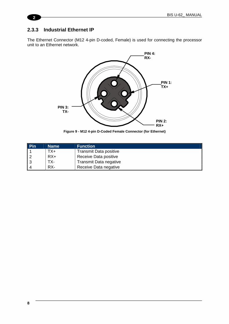
2.3.3 Industrial Ethernet IP The Ethernet Connector (M12 4-pin D-coded, Female) is used for connecting the processor unit to an Ethernet network.
Figure 9 - M12 4-pin D-Coded Female Connector (for Ethernet)
Pin Name Function 1 TX+ Transmit Data positive 2 RX+ Receive Data positive 3 TX- Transmit Data negative 4 RX- Receive Data negative
PIN 4:RX-
PIN 1:TX+
PIN 3:TX-
PIN 2:RX+

INSTALLATION
9
2
The Industrial Ethernet models are powered through their VDC power connector (M12 5-pin, Male).
Figure 10 - M12 5-pin Male Connector (for Power Supply) Pin Name Function 1 nc 2 VDC Input Power 3 GND Power Ground 4 nc 5 nc
PIN 4:N/C
PIN 3:GND
PIN 5:N/C
PIN 1:N/C
PIN 2:VDC

BIS U-62_ MANUAL
10
2
2.3.4 Digital I/O (-12 models) The Digital I/O Connector (M12 8-pin Female Connector) is used for connecting the processor unit to optional external digital input/output devices. See par. 2.7 for further details.
Figure 11 - M12 8-pin Female Connector (Digital I/O)
Pin Name Function 1 Vdc Power from the processor unit to the I/O device 2 GND Power Ground 3 O1+ Output 1 positive 4 O1-c Output 1 negative 5 O2+ Output 2 positive 6 O2- Output 2 negative 7 I1A Input 1A (optocoupled polarity insensitive) 8 I1B Input 1B (optocoupled polarity insensitive)
CAUTION
The Vdc and Ground pins on this connector must not be used to power the processor unit. They can only be used to optionally supply the I/O device within the limits specified in par. 2.7 and in the Technical Features.

INSTALLATION
11
2
2.4 POWER & WIRING The information presented below is provided to assist the installer in determining the amount of power that will be required by the UHF-Processor unit depending on the application. 2.4.1 Power Requirements The UHF-Series processor unit requires an electrical supply voltage of 12 to 30 Vdc. Use a regulated power supply that is capable of delivering the requirements listed in the Technical Features. For point-to-point or individually powered slave nodes, the calculation is straight forward. The calculation becomes more complex for network power sources. The following information is provided to assist you in determining the power requirements of an RFID network application, in particular a Subnet16™ network.
NOTE
Power is applied directly to the Subnet16™ Network trunk and distributed through drop cables to the Gateway and RFID processor units. By positioning the power supply near the middle of the network, you can limit voltage drop at the ends, (see par. 2.6.2 for network layout diagrams).
2.4.2 Total System Current Consumption
NOTE
The current consumption values of each product are given in the Technical Features paragraph of the relative Installation manual and refer to the min and max input voltage range. These values already include an adequate safety margin. The consumption values given in the following examples have been interpolated for an input voltage of 24 Vdc.
Max Gateway Current: 200 mA @ 12 Vdc (133 mA @ 24 Vdc). Max Processor unit Current: 380 mA @ 24 Vdc for BIS U-62_-Series Calculating Total System Current Consumption:
Total System Current Consumption = [Max Gateway Current + (Max Processor unit Current x Number of Processor units)]
Example A Subnet16™ network powered at 24 Vdc is composed of a BIS Z-GW-001_ connecting eight BIS U-620-067_Processor units.
Total System Current Consumption = [0.133 A + (0.380 A X 8)] = 3.173 A

BIS U-62_ MANUAL
12
2
2.4.3 Cable Voltage Drop In addition, each RFID processor unit on the Subnet will experience a certain amount of voltage drop depending on the length of the cable. Cable Resistance per Meter
• ThinNet = 0.058 ohms per meter per wire
• ThickNet = 0.0105 ohms per meter per wire Calculating Voltage Drop
Voltage Drop = (Max Processor unit Current x Number of Processor units) x (Cable Resistance per Meter per Wire1 x Cable length in Meters)
Example A Subnet16™ network is composed of a BIS Z-GW-001_ connecting eight BIS U-620-067_Processor units (380 mA each @ 24 Vdc). A total of 20 meters of ThinNet cables are used to connect the devices, which have Cable Resistance = 0.058 Ohms per meter per wire. The network power is 24 Vdc. The voltage drop calculation must be conducted on the RFID processor unit that is farthest from the Power Supply, as it will experience the greatest voltage drop.
NOTE
It is always recommended to power the network from the middle (T-configuration), to reduce total voltage drop at the ends. In the example below this allows the fourth processor unit and not the eighth to be the furthest from the power supply.
Voltage Drop = [0.133 A GWY + (0.380 A x 8 processor units)] x [(0.058 x 2) x 20 meters] = 7.36 Vdc
24 Vdc - 7.36/2 = 20.32 Vdc at processor unit number 4 of each branch 2.4.4 Current Rating for Cables The maximum current rating for the Subnet16™ network using Balluff cables and accessories (BCCxxxx), is 4.0 A.
1 The resistance calculation must include both wires (Vdc and GND).

INSTALLATION
13
2
2.5 INSTALLATION GUIDELINES 2.5.1 Hardware Requirements The following is a list of minimum components required to create a UHF RFID reading system. Other components may be required depending on the processor unit model, see the specific installation procedure for your model.
• Host computer with specific interface (Serial, Subnet16™ or Fieldbus); Programmable Logic Processor unit (PLC) or PC
• RFID processor unit(s) (BIS U-62_ Series Processor units)
• Adequate length cabling, connectors and terminators
• Sufficient power capable of powering all the RFID components
• Balluff RFID series tags: EPC Class 1 Gen 2 2.5.2 Installation Precautions
• RF performance and read/write range can be negatively impacted by the proximity of metallic objects and liquids. Avoid mounting the BIS U-30_ antenna within 15 cm (6 inches) of any metallic object or wet surface.
• Do not route cables near other unshielded cables or near wiring carrying high voltage or high current. Cross cables at perpendicular intersections and avoid routing cables near motors and solenoids.
• Avoid mounting the processor unit near sources of EMI (electro-magnetic interference) or near devices that generate high ESD (electro-static discharge) levels. Always use adequate ESD prevention measures to dissipate potentially high voltages.
• If electrical interference is encountered (as indicated by a significant reduction in read/write performance), relocate the processor unit to an area free from potential sources of interference.

BIS U-62_ MANUAL
14
2
2.6 TYPICAL LAYOUTS AND INSTALLATION PROCEDURES 2.6.1 Installing the BIS U-620-068_ RS232
Figure 12 - RS232 Typical Layouts
The BIS U-620-068_ Processor unit is designed for point-to-point RFID applications, where the distance from host to processor unit is less than 15 meters (50 feet). The processor unit connects directly to a serial communications port on a host computer via an RS232-compatible serial interface cable.
1. Select a suitable location for the BIS U-62_ processor unit and BIS U-30_ Antenna.
2. Mount the BIS U-30_ Antenna (within the cable distance of the UHF Processor unit) and attach the BIS U-500_ Antenna cable as described in par. 2.2.
3. Fasten the processor unit to your mounting fixture using two M5 (#10) diameter screws (not included) and secure them with appropriate washers and nuts. Tighten screws to 1.7 Nm or 15 lbs per inch ± 10%. Connet the antenna cable to the UHF Processor unit.
4. Connect the BCC0ETJ M12 8-pin female connector to the M12 8-pin male interface connector on the BIS U-620-068_. Connect the BCC0ETJ 9-pin female D-sub connector to an RS232 COM port on the host computer. Tighten the cable’s two locking thumbscrews.
5. Connect the power supply to the VDC (red) and GND (black) wires on the BCC0ETJ cable.
6. Apply power to the processor unit after all cable connections have been made. The LEDs on the unit will flash. The READY LED is ON after the power up sequence has completed.
7. On the host computer, set the COM port parameters to: 9600 baud, 8 data bits, 1 stop bit, no parity and no handshaking.
To verify operations, download the Balluff Dashboard™ Configuration Tool from www.balluff.com. The Balluff Dashboard™ Configuration Tool allows users to configure and control their BIS U-620-068_ processor units and send RFID commands for testing purposes. See the Balluff Dashboard™ Manual for details.
BIS
U-6
20-0
68_
BCC0ETJ
Host
Power Supply
Vdc (red)
GND (black)
BIS U-30_

INSTALLATION
15
2
2.6.2 Installing the BIS U-620-067_ RS485
Figure 13 - RS485 Typical Layouts
The BIS U-620-067_ Processor unit is designed for Subnet16™ RFID applications, where the processor unit is connected in an RS485 network via Subnet16™-compatible cables to the host through a Gateway or Hub.
1. Select a suitable location for the BIS U-62_ processor unit and BIS U-30_ Antenna.
2. Mount the BIS U-30_ Antenna (within the cable distance of the UHF Processor unit) and attach the BIS U-500_ Antenna cable as described in par. 2.2.
3. Fasten the processor unit to your mounting fixture using two M5 (#10) diameter screws (not included) and secure them with appropriate washers and nuts. Tighten screws to 1.7 Nm or 15 lbs per inch ± 10%. Connet the antenna cable to the Processor unit.
4. Attach a Subnet16™ compatible cable (i.e. BCC0ET0) to the M12 5-pin male Subnet16™ connector on the processor unit. Connect the other end of this cable to your Subnet16™ network.
5. To complete the Subnet16™ network installation, including power supply wiring, trunk wiring, network termination, Gateway/Hub wiring, and for a complete list of compatible accessory cables and Subnet16™ network layout examples, see the Subnet16™ Gateway or Subnet16™ Hub Manuals.
After installation, the Subnet16™ network can be configured through the Subnet16™ Gateway/Hub using the Balluff Dashboard™ Configuration Tool. See the Balluff Dashboard™ Configuration Tool Manual for details.
BCC07WR
BCC0ET0
BCC07WR BCC07WR
BCC07WR
BCC07WR BCC07WR
BCC0ET0 BCC0ET0 BCC0ET0
BCC
09M
R
BCC
0ET4
Gateway
To Host
To C
onfig
urat
ion
PC
To Power Supply
Vdc GND
BCC
09M
R
BCC06ZF
BIS
U-6
20-0
67-
BCC
0ET0
BIS U-30x…
antenna
BIS
U-6
20-0
67-
BCC
0ET0
BIS U-30x… antenna
BIS
U-6
20-0
67-
BCC
0ET0
BIS U-30x… antenna
BIS
U-6
20-0
67-
BCC
0ET0
BIS U-30x… antenna

BIS U-62_ MANUAL
16
2
2.6.3 Installing the BIS U-626-069_ Industrial Ethernet (IND)
Figure 14 - IND Typical Layouts
The BIS U-626-069_ Processor unit is designed for Industrial Ethernet IP RFID applications, where the processor unit is connected in an Ethernet IP or TCP/IP network via compatible cables through a hub or directly to an Ethernet IP host.
1. Select a suitable location for the BIS U-62_ processor unit and BIS U-30_ Antenna.
2. Mount the BIS U-30_ Antenna (within the cable distance of the UHF Processor unit) and attach the BIS U-500_ Antenna cable as described in par. 2.2.
3. Fasten the processor unit to your mounting fixture using two M5 (#10) diameter screws (not included) and secure them with appropriate washers and nuts. Tighten screws to 1.7 Nm or 15 lbs per inch ± 10%. Connect the antenna cable to the UHF Processor unit.
4. Connect the BCC0CT1 M12 4-pin male connector to the M12 4-pin female interface connector on the BIS U-626-069_. Connect the BCC0CT1 RJ45 male connector to the LAN hub/switch. If connecting directly to the host computer you will need to use an additional crossover cable.
5. Build a power supply cable using the BCC06ZF M12 5-pin female connector. Use minimum 24 AWG wires for connection to the power supply lines according to the Vdc connector pinout. Connect the BCC06ZF M12 5-pin female connector to the M12 5-pin male connector on the processor unit. Connect the other end of the cable (wires or user-supplied connectors) to the power supply.
6. Apply power to the processor unit after all cable connections have been made. The LEDs on the unit will flash. The READY LED is ON after the power up sequence has completed. Then one of the Ethernet IP Address LEDs will remain on, either Default or Custom.
To verify operations, download the Balluff Dashboard™ Configuration Tool from www.balluff.com. The Balluff Dashboard™ Configuration Tool allows users to configure and control their BIS U-626-069_ processor units and send RFID commands for testing purposes. See the Balluff Dashboard™ Configuration Tool Manual for details.
BIS
U-6
26-0
69
Vdc
BCC0CT1
Hub
PLC
BCC06ZF
BIS U-30x… antenna
to Power Supply GND

INSTALLATION
17
2
2.7 DIGITAL I/O (-ST29; -ST30 OR -ST31 MODELS) 2.7.1 Input There is one optocoupled polarity insensitive input available on the Processor units with the I/O option. See par. 2.3.4 for pinout. “Polarity Insensitive” means that, in the applications examples shown below, the user can exchange I1A with I1B without affecting the system behaviour. The user can handle the input through specific commands (see par. 2.7.3 for the specific Balluff Command Protocol Manual according to your processor unit model). The electrical features of the input are:
Maximum voltage: 30 Vdc
Minimum voltage: 6 Vdc
Maximum current: 28 mA The input is optocoupled and can be driven by both an NPN and PNP type command.

BIS U-62_ MANUAL
18
2
Input Connections Using Processor unit Power
Figure 15 - PNP External Trigger Using Processor unit Power
Figure 16 - NPN External Trigger Using Processor unit Power
Input Connections Using External Power
Figure 17 - PNP External Trigger Using External Power

INSTALLATION
19
2
Figure 18 - NPN External Trigger Using External Power
2.7.2 Outputs Two general purpose optocoupled outputs are available on the Processor units with the I/O option. See par. 2.3.4 for pinout. The user can activate/deactivate the two outputs through specific commands (see par. 2.7.3 for the specific Balluff Command Protocol Manual according to your processor unit model). When connected to an external circuit, the current must enter in O1+/O2+ and exit from O1-/O2-. The electrical features of the outputs are:
Voltage Range: 6 ~ 30 Vdc
Maximum Current: - If externally powered (by the user): 500 mA - If powered by the processor unit (pins 1 and 2 of the I/O connector): max. 300 mA
(*) (*) This is the maximum value of current computed as the sum of both the Outputs! In fact the output current supplied by the processor unit is limited. In other words if only one output is active the maximum current value is 300 mA, but if both the outputs are active then each Output current must decrease (for example max. 150 mA for each Output). Notes
- It should be noted that if the power supply for the I/O is supplied by the Processor unit (pins 1 and 2), the opto-isolation feature for the Input and Output sections will be lost, because the ground of the I/O and the Processor unit power supply is the same.
- A device that operates at 200 mA may damage the Digital Output due to inrush current if a current limiting device is not used and the current exceeds 500 mA (e.g. an incandescent light).
- The inductive "kick" that occurs when a relay is released (back EMF from a collapsing magnetic field) can impose a voltage higher than 30 Vdc that may damage the output transistor. To avoid this potential issue, employ a diode (D1) to clamp the back EMF. D1 should be a 1N4001 or equivalent.

BIS U-62_ MANUAL
20
2
The following connection diagrams show examples involving only Output1; the same principles are valid and applicable also to Output2. Output Connections Using Processor unit Power
Figure 19 - Open Emitter (Sourcing) Output Using Processor unit Power
Figure 20 - Open Collector (Sinking) Output Using Processor unit Power

INSTALLATION
21
2
Output Connections Using External Power
Figure 21 - Open Emitter (Sourcing) Output Using External Power
Figure 22 - Open Collector (Sinking) Output Using External Power

BIS U-62_ MANUAL
22
2
Figure 23 - Open Collector (Sinking) Output for a LED Using External Power
Note
- The resistor R1 in series with the LED LD1 sets the forward current; a value of 1.2 kΩ will provide about 20 mA LED current, when run from 24 Vdc.
2.7.3 Digital I/O Command Control To handle the Input and Outputs, a set of CBx and ABx commands are available for the user. These commands include getting the status and setting/clearing the Input/Outputs. For more details, refer to the Balluff CBx Command Protocol Manual, and the Balluff ABx Fast Command Protocol Manual, both available on the Balluff web site in the download section of the product page. To determine which command protocol to utilize, please refer to the list below for the different Balluff devices. CBx Protocol
• BIS U-62_-Series Fieldbus and Non Fieldbus models: Industrial Ethernet (IND), ABx Protocol (Fast and Standard)
• BIS U-620-068_ Serial models: RS232
NOTE
All RS485-based RFID processor units are used in conjunction with Subnet16™ Gateway and Subnet16™ Hub interface modules, which all use the CBx Command Protocol.
LED INDICATORS
1
3
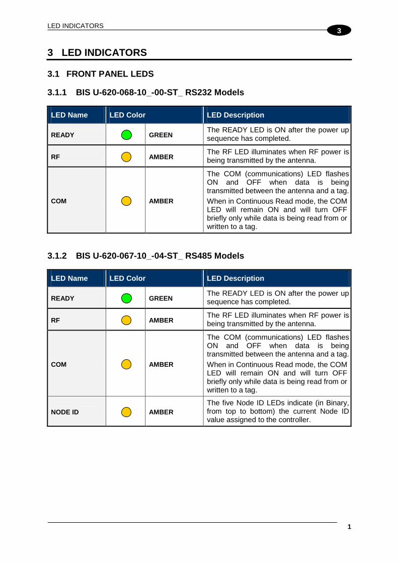
3 LED INDICATORS 3.1 FRONT PANEL LEDS 3.1.1 BIS U-620-068-10_-00-ST_ RS232 Models
LED Name LED Color LED Description
READY GREEN
The READY LED is ON after the power up sequence has completed.
RF AMBER The RF LED illuminates when RF power is being transmitted by the antenna.
COM AMBER
The COM (communications) LED flashes ON and OFF when data is being transmitted between the antenna and a tag. When in Continuous Read mode, the COM LED will remain ON and will turn OFF briefly only while data is being read from or written to a tag.
3.1.2 BIS U-620-067-10_-04-ST_ RS485 Models
LED Name LED Color LED Description
READY GREEN
The READY LED is ON after the power up sequence has completed.
RF AMBER The RF LED illuminates when RF power is being transmitted by the antenna.
COM AMBER
The COM (communications) LED flashes ON and OFF when data is being transmitted between the antenna and a tag. When in Continuous Read mode, the COM LED will remain ON and will turn OFF briefly only while data is being read from or written to a tag.
NODE ID AMBER The five Node ID LEDs indicate (in Binary, from top to bottom) the current Node ID value assigned to the controller.
UHF-SERIES REFERENCE MANUAL
2
3
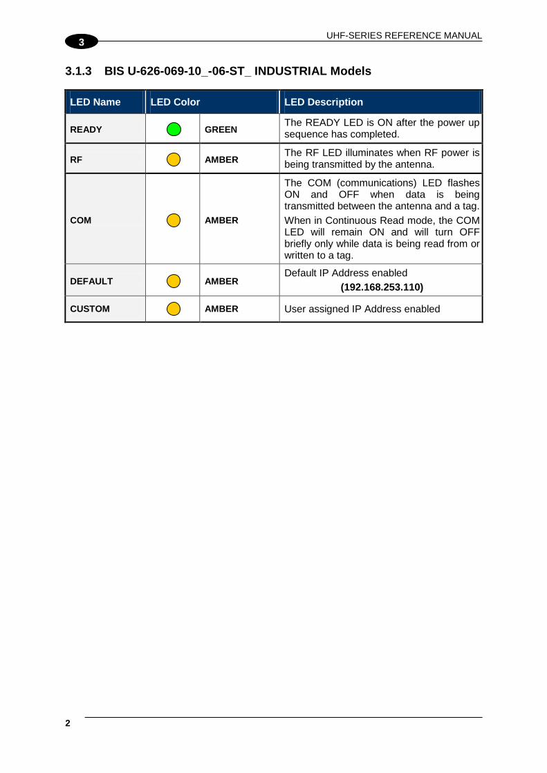
3.1.3 BIS U-626-069-10_-06-ST_ INDUSTRIAL Models
LED Name LED Color LED Description
READY GREEN
The READY LED is ON after the power up sequence has completed.
RF AMBER The RF LED illuminates when RF power is being transmitted by the antenna.
COM AMBER
The COM (communications) LED flashes ON and OFF when data is being transmitted between the antenna and a tag. When in Continuous Read mode, the COM LED will remain ON and will turn OFF briefly only while data is being read from or written to a tag.
DEFAULT AMBER Default IP Address enabled
(192.168.253.110)
CUSTOM AMBER User assigned IP Address enabled

CONFIGURATION METHODS
1
4
4 CONFIGURATION METHODS There are several configuration methods available for your processor unit depending on the interface type and application:
• Configuration Tag
• Configuration Tools: Balluff Dashboard™ and C-Macro Builder™
• Command Protocol 4.1 CONFIGURATION TAG A configuration tag is included with your BIS U-62_ processor unit. This can be used to reset all BIS U-62_ processor units to their factory default configuration settings. For Subnet16™ models (BIS U-620-067-10_ ), this tag can also be used to set the Node ID of each processor unit in the network.
Figure 24 - UHF-Series Configuration Tag
4.1.1 Node ID Configuration Using Configuration Tags Only RS485-based RFID processor units can be connected to a Gateway’s Subnet network and each must be assigned a unique Node ID value between 1 and 16. When an RFID processor unit is connected to the Gateway’s Subnet network, the Gateway will query the new processor unit to obtain certain configuration values (specifically the Node ID number). If the Gateway does not detect a Node ID conflict, it will “allow” the RFID processor unit onto the Subnet network. By using the BIS U Configuration Tag that is included with each RS485-based BIS U-62_ Processor unit, the Node ID value can be dynamically assigned by the Gateway or can be manually assigned by the user. For the Gateway to dynamically assign a Node ID value to a processor unit, the processor unit must first be initialized with the Node ID value of zero. This is the equivalent of having no Node ID assigned.

BIS U-62_ MANUAL
2
4
NOTE
All Balluff RS485-based processor units’ ship with their Node ID value set to 0.
When a powered processor unit (that is set to Node ID 0) is connected to the Subnet, it will not initially be recognized by the Gateway until the Configuration Tag is placed in the antenna’s RF field. After a few seconds the processor unit will display its new assigned Node ID value in binary code from right to left or (top to bottom) using the five amber Node LEDs on the processor unit. When dynamically assigning a Node ID value for a new processor unit, the Gateway will either assign the next available Node ID value or the value that the Gateway recognizes as offline or “missing” – that is, a Node ID value that previously existed, but has since disappeared from the network. Because the Gateway stores a backup of each Subnet Node’s configuration, should an RFID processor unit ever fail, a replacement processor unit can be installed quickly and easily. The new processor unit will be automatically assigned the same Node ID value and configuration as the replaced processor unit, provided the Configuration Tag is introduced to the antenna field after startup and then removed.
NOTE
Avoid that the configuration tag is simultaneously read by more than one processor unit, especially for UHF processor units.
4.2 CONFIGURATION TOOLS Balluff offers the following powerful RFID configuration utilities for Microsoft Windows 2000, XP, Vista and 7 systems:
• Balluff Dashboard™
• C-Macro Builder™ These configuration tools can be downloaded from the Balluff website: www.balluff.com

CONFIGURATION METHODS
3
4
4.2.1 Configuration Using Balluff Dashboard™ The Balluff Dashboard™ Utility is a software application that allows users to view, modify, save and update the configuration settings of their BIS U-62_ processor units. Follow the instructions below to operate the Balluff Dashboard™ Configuration Tool and to set the BIS U-62_ device’s configuration.
1. Install the Processor unit as described in the relevant sub-paragraph in 2.6.
2. Connect the Processor unit to your PC, power up and wait for the boot procedure to finish.
3. Run the Balluff Dashboard™.
4. From the Connection screen, choose your processor unit from the list.
Figure 25 - Balluff Dashboard™ Gateway Profibus Selection
5. Choose the appropriate COM port and Baudrate (or IP Address for Ethernet models);
then click “Connect”.
Figure 26 - Balluff Dashboard™ COM and Baudrate Selection
BIS U-62_ MANUAL
4
4
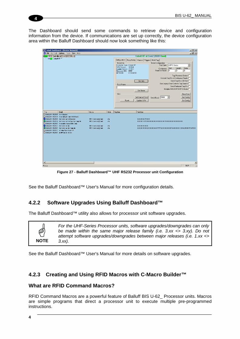
The Dashboard should send some commands to retrieve device and configuration information from the device. If communications are set up correctly, the device configuration area within the Balluff Dashboard should now look something like this:
Figure 27 - Balluff Dashboard™ UHF RS232 Processor unit Configuration
See the Balluff Dashboard™ User's Manual for more configuration details. 4.2.2 Software Upgrades Using Balluff Dashboard™ The Balluff Dashboard™ utility also allows for processor unit software upgrades.
NOTE
For the UHF-Series Processor units, software upgrades/downgrades can only be made within the same major release family (i.e. 3.xx <> 3.xy). Do not attempt software upgrades/downgrades between major releases (i.e. 1.xx <> 3.xx).
See the Balluff Dashboard™ User's Manual for more details on software upgrades. 4.2.3 Creating and Using RFID Macros with C-Macro Builder™ What are RFID Command Macros? RFID Command Macros are a powerful feature of Balluff BIS U-62_ Processor units. Macros are simple programs that direct a processor unit to execute multiple pre-programmed instructions.

CONFIGURATION METHODS
5
4
Because macros reside within the processor unit’s internal memory, they can be programmed to instruct the processor unit to automatically read and/or write a specified set of data to an RFID tag without the processor unit ever having to receive a command from the host. In fact, the processor units do not even require a connection to a host in order to execute macros. Each macro can contain up to 255 bytes of data and each supported processor unit can store up to eight macros at a time. Though they are stored locally on the processor unit, macros are also backed up in the Gateway’s flash memory as well. Why use macros? The power of macros is in distributed intelligence, the reduction in network bus traffic and the ability to accelerate routine decision making at the point of data collection. What can macros do? In addition to the automated reading and writing of data, macro capabilities include:
• The ability to write time stamps to RFID tags
• The ability to filter command responses to only those of interest to the host (such as when an error occurs or when a tag has arrived in the RF field)
• The ability to harness powerful logic and triggering capabilities such as; read, write, start/stop continuous read, data compare, branch, transmit custom string, and set outputs.
What is a macro trigger? Macros are initiated by “triggers.” Triggers can be configured in numerous ways. A simple command from the host, such as “execute macro number three” can be considered a trigger. Triggers can be configured, for example, to activate a macro when a tag enters or leaves a processor unit’s RF field. Balluff RFID processor units can store up to eight separate triggers in addition to the eight macros they can also house. Any trigger can activate any of the eight stored macros. How are macros created? Macros are created using the powerful, yet simple, C-Macro Builder™ utility from Balluff. The easy to use GUI allows the user to create powerful RFID macro programs quickly and easily. When used with Balluff Balluff Dashboard™ utility, users can effortlessly download, erase, and manage their macros and triggers, as well as set the operational configurations of their RFID processor units and Subnet16™ Gateways.

BIS U-62_ MANUAL
6
4
Which communication interfaces support the use of macros? Macros are supported on the following BIS U-62_ Processor units: Ethernet, Profibus, Profinet, DeviceNet, RS232 and USB interfaces. What happens to existing Macros if a processor unit must be replaced? When using a Subnet16™ Gateway, users do not need to worry. Macros and triggers normally residing in an RFID processor unit’s flash memory are always backed up in the Gateway’s flash memory as well. Therefore, if a processor unit should ever require replacement, all existing macro and trigger settings are automatically exported from the Gateway to the new RFID processor unit. In short, when an RFID processor unit is initially connected to the Gateway, macro and trigger data from the processor unit’s flash memory is compared to the macro and trigger data backed up in the Gateway from the previous RFID processor unit. If the data does not match that which is stored on the Gateway, the processor unit’s flash memory will be overwritten with the backed up data stored in the Gateway’s flash memory. How can I learn more about the Dashboard and C-Macro Builder? More information regarding macros, triggers, uploading, downloading, configuring and monitoring Balluff RFID equipment is available in the respective User’s Manuals for these products, which are available on the Balluff website at:
www.balluff.com

CONFIGURATION METHODS
7
4
C-Macro Builder™ is an easy to use GUI-driven utility for Windows that allows users to create powerful RFID command macro programs.
Figure 28 - C-Macro Builder™
NOTE
For specific information regarding the configuration and use of either of these utilities, please see the accompanying documentation included when downloading each software application.

BIS U-62_ MANUAL
8
4
4.3 COMMAND PROTOCOLS UHF-Series processor units can be directly programmed using a proprietary command protocol over the specific host interface. This is useful for processor units connected to a PLC over a Fieldbus network (i.e. Ethernet/IP). To determine which command protocol to utilize, please refer to the list below for the different BIS U-62_ RFID devices. CBx Protocol
• BIS U-62_ Series (Fieldbus and Non-Fieldbus) models: Industrial Ethernet (IND) ABx Protocol (Fast and Standard)
• BIS U-62_ Series Serial models: RS232
NOTE
All RS485-based RFID processor units are used in conjunction with Subnet16™ Gateway and Subnet16™ Hub interface modules, which all use the CBx Command Protocol.
Refer to the specific Command Protocol Reference Manual for details.

ETHERNET/IP INTERFACE
1
5
5 ETHERNET/IP INTERFACE
NOTE
For BIS U-626-069_ models.
• Users of the BIS U-626 Dashboard utility should exit the application before attempting communications between the Industrial BIS U-626 and an EtherNet/IP host Programmable Logic Controller (PLC).
• When installing the Controller for communication over EtherNet/IP, the ODVA Guidelines for EtherNet/IP Media System installation should be followed (refer to www.odva.org, ODVA PUB00148R0 (Pub 148), EtherNet/IP Media Planning and Installation Manual, 2006 ODVA).
• Follow ODVA recommendations for switching and wiring Ethernet/IP.
• If the Ethernet/IP network enables I/O Messaging for remote I/O, etc., or if other UDP traffic is present, then the Controller must be protected by a switch that incorporates IGMP Snooping or a VLAN.
The BIS U-626-069_ model is designed to support many common Industrial Ethernet protocols and can be implemented in a wide variety of existing host / PLC applications. One such popular Ethernet protocol is Ethernet/IP (EIP). This chapter focuses on the process of setting up the BIS U-626 Industrial Processor units to communicate (via Ethernet/IP) with a ControlLogix Programmable Logic Controller (PLC). Also in this chapter are descriptions of the Balluff HTTP Server and OnDemand Utilities, as well as systematic instructions to help configure the BIS U-626 Industrial Processor units for Ethernet/IP environments.
NOTE
This manual assumes that users are already familiar with Ethernet/IP, industrial Ethernet communications protocols and programmable logic controller technologies. For specific information regarding the protocol used by your particular RFID application, please refer to the appropriate documentation from your host / PLC program provider.

BIS U-62_ MANUAL
2
5
5.1 ETHERNET/IP CONFIGURATION OVERVIEW Based upon on the standard TCP/IP protocol suite, EtherNet/IP is a high-level application layer protocol for industrial automation applications that uses traditional Ethernet hardware and software to define an application layer protocol that structures the task of configuring, accessing and controlling industrial automation devices. Ethernet/IP classifies Ethernet nodes as predefined device types with specific behaviors. The set of device types and the EIP application layer protocol is based on the Common Industrial Protocol (CIP) layer used in ControlNet. Building on these two widely used protocol suites, Ethernet/IP provides a seamlessly integrated system from the RFID Subnet network to the Host and enterprise networks. The BIS U-626 is designed to communicate as an EtherNet/IP client device, which will receive and execute RFID commands issued by the host / PLC (acting as EtherNet/IP Server). Paragraphs 5.3 through 5.7 contain instructions that will help you accomplish the following:
• Assign the BIS U-626 an IP address via HTTP Server
• Configure the BIS U-626’s Subnet Node via OnDemand Utilities
• Create “Controller Tags” in the PLC
• Verify PLC and BIS U-626 Subnet Node connectivity 5.2 HTTP SERVER & ONDEMAND PLC SUPPORT Below is a partial list of the programmable logic controllers that are supported by the Balluff HTTP Server and OnDemand Utilities:
• ControlLogix – OnDemand supports all current versions
• RA’s PLC5E releases:
• Series C, Revision N.1
• Series D, Revision E.1
• Series E, Revision D.1
• PLC5 "Sidecar" Module Series B, Revision A with EIP support
• SLC5/05 releases:
• Series A with firmware revision OS501, FRN5
• All Series B and Series C PLC Controllers

ETHERNET/IP INTERFACE
3
5
5.3 HTTP SERVER AND ONDEMAND UTILITIES Embedded in the BIS U-626-069_ is an HTTP Server, which provides a Website-like interface and a suite of configuration tools. Through the use of the BIS U-626’s HTTP Server, users can access, modify and save changes to the unit’s Industrial Ethernet configuration, IP address, and OnDemand mode settings. The OnDemand Utilities will be used later in this chapter to link the BIS U-626 to specific Controller Tags as defined in Rockwell Automation’s (RA) ControlLogix PLC.
CAUTION
Disable any firewall services affecting or running locally on the host computer. Firewalls can potentially block communications between the BIS U-626 and the host and/or PLC.
NOTE
In ControlLogix, a “Controller Tag” is a small block of internal memory that is used to hold outgoing (command) and incoming (response) data. Within each controller tag, information is stored in two-byte segments, known as registers or “words.”
OnDemand is the Balluff approach to adding Change of State messaging to ControlLogix and legacy support for RA PLC5E and RA SCL5/05 programmable logic controllers.

BIS U-62_ MANUAL
4
5
5.4 IP CONFIGURATION VIA HTTP SERVER To configure the BIS U-626 for Ethernet communications, begin by assigning the controller a locally compatible IP address. Through a standard Web browser, you can utilize the BIS U-626’s HTTP Server to access an embedded suite of controller configuration tools, called the “OnDemand Utilities.” Among its features is the ability to modify and save changes to the controller’s IP address, which is stored internally on the BIS U-626.
BIS U-626 Industrial Ethernet Processor units - Default IP Address: 192.168.253.110
Setting the BIS U-626 IP Address To set the BIS U-626’s IP address using the HTTP Server, follow the steps below:
1. Open a Web browser on the PC.
2. In the URL address field, enter the BIS U-626’s IP address (192.168.253.110 = factory default).
3. Press ENTER. The HTTP Server - Main Page will be displayed. HTTP Server – Main Page
Figure 29 - The HTTP Server - Main Page
The HTTP Server - Main Page lists the IP address and network settings currently stored on the BIS U-626.
ETHERNET/IP INTERFACE
5
5
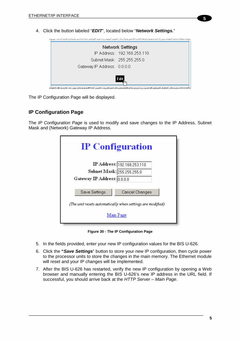
4. Click the button labeled “EDIT”, located below “Network Settings.”
The IP Configuration Page will be displayed. IP Configuration Page The IP Configuration Page is used to modify and save changes to the IP Address, Subnet Mask and (Network) Gateway IP Address.
Figure 30 - The IP Configuration Page
5. In the fields provided, enter your new IP configuration values for the BIS U-626.
6. Click the “Save Settings” button to store your new IP configuration, then cycle power to the processor units to store the changes in the main memory. The Ethernet module will reset and your IP changes will be implemented.
7. After the BIS U-626 has restarted, verify the new IP configuration by opening a Web browser and manually entering the BIS U-626’s new IP address in the URL field. If successful, you should arrive back at the HTTP Server – Main Page.

BIS U-62_ MANUAL
6
5
5.5 ONDEMAND CONFIGURATION FOR ETHERNET/IP Now that you have configured the BIS U-626’s IP address, you will need to use the embedded HTTP Server to access the BIS U-626’s OnDemand Configuration Page. Through the use of the OnDemand Configuration Page, the BIS U-626 can be configured to communicate with a ControlLogix PLC. To configure the BIS U-626’s OnDemand Configuration settings, follow the steps below:
1. Open a Web browser on the host and enter the BIS U-626’s new IP address in the URL field. The HTTP Server – Main Page will be displayed.
2. At the HTTP Server – Main Page, click the button labeled “OnDemand Config.”
The OnDemand Configuration Page will be displayed.

ETHERNET/IP INTERFACE
7
5
OnDemand Configuration Page The OnDemand Configuration Page allows you to modify the settings of the BIS U-626’s Node.
Figure 31 - The OnDemand Configuration Page
3. In the upper portion of the OnDemand Configuration Page, select a PLC Type from the drop-down menu.
Figure 32 - The OnDemand Configuration Page
4. Enter the PLC’s IP address.

BIS U-62_ MANUAL
8
5
5. For the PLC Slot Number, enter a value between 0 and 255. The PLC Slot Number indicates the location in your PLC rack where the processor units module is installed (normally slot 0 for ControlLogix).
6. In the Read Delay field, enter a value between 0 and 6000. This number specifies (in 10ms “ticks”) how frequently the BIS U-626 will poll the PLC for the presence of new data. (Note: a value of 6000 = 60 seconds; zero = disable).
7. In the column labeled “Enable Node,” place a check in the box for Node 01. Other Nodes listed on this page are not supported by the BIS U-626-069_.
8. Write Size: Enter a value between 1 and 100 (or 0 to disable) for the Write Size. The
Write Size represents the maximum number of 2-byte “words” that the BIS U-626 will attempt to write to PLC memory during a single write cycle. (Note: to accommodate message handshaking overhead, the actual data size required by the PLC is three words larger than the value specified in this field).
9. Write Tag Name: For ControlLogix systems, specify a Write Tag Name that is 40 characters or less (for example EMS_WRITE1, for Node 01). The Write Tag Name is a user defined description or title for the area of memory in the PLC where host-bound data will be written for the BIS U-626. (Note: the Write Tag Name is not to be confused with writing to an RFID transponder, which is often referred to as “writing to a tag”).
OR
Write Tag Name: For PLC5E, SLC5/05 and MicroLogix systems, enter the PCCC File Number and Offset (for example N7:0) in the Write Tag Name field. Together these values identify the location in the PLC’s Status File where host-bound data will be written for the BIS U-626.
10. Read Size: Enter a value between 1 and 100 (or 0 to disable) for the Read Size. The Read Size represents the maximum number of 2-byte “words” that the BIS U-626 will attempt to retrieve from PLC memory during a single read cycle. (Note: to accommodate message handshaking overhead, the actual data size required by the PLC is three words larger than the value specified in this field).
11. Read Tag Name: For ControlLogix systems, specify a Read Tag Name that is 40 characters or less (for example EMS_READ1, for Node 01). The Read Tag Name is a user defined description or title for the area of memory in the PLC from which the BIS U-626 will retrieve data.
OR
Read Tag Name: For PLC5E, SLC5/05 and MicroLogix systems enter the PCCC File Number and Offset in the Read Tag Name field. Together these values indicate the location in the PLC’s Status File from which the BIS U-626 will retrieve data.
12. After entering the proper information for Node 01, click the Save Settings button located at the bottom of the page.

ETHERNET/IP INTERFACE
9
5
The OnDemand Status Page will be displayed.
13. At the OnDemand Status Page, click the link labeled “Main Page” to return to the HTTP Server – Main Page.
5.6 CONFIGURING PLC CONTROLLER TAGS After you have configured the BIS U-626’s Node via the OnDemand Configuration Page, open your PLC program (i.e. RSLogix 5000) and, if you have not already done so, define two Controller Tags (a Write Tag and a Read Tag). Controller Tag Naming Controller Tags need to be assigned a name and size. Be sure to use the same Write Tag Name and Read Tag Name that you specified in the OnDemand Node Configuration (i.e., EMS_WRITE1 and EMS_READ1). Controller Tag Size Due to handshaking overhead, Controller Tags must have the size capacity to store an integer array equal to your previously specified Write/Read Size + three words. So for example, if the Read Size you specified earlier was 100 words, the corresponding Read Tag in the PLC must be able to store an array of 103 integers.
• The Write Tag holds messages and response data generated by the BIS U-626 that is bound for the host or PLC.
• The Read Tag holds RFID commands and instructions intended for the BIS U-626.

BIS U-62_ MANUAL
10
5
NOTE
The BIS U-626 should already be linked to the proper Write Tag and Read Tag via the OnDemand Utilities - OnDemand Configuration Page).
After creating and defining a Write Tag and a Read Tag for the BIS U-626, return to the BIS U-626’s HTTP Server – Main Page to continue.
ETHERNET/IP INTERFACE
11
5
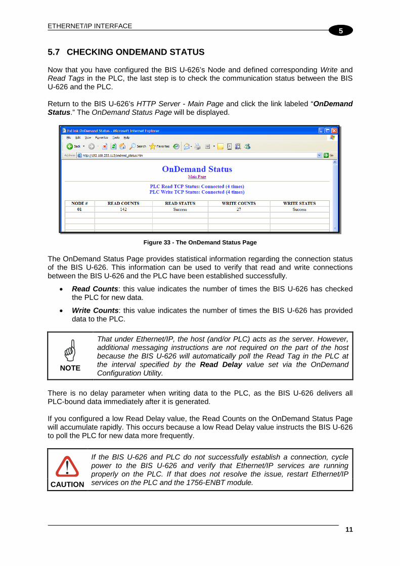
5.7 CHECKING ONDEMAND STATUS Now that you have configured the BIS U-626’s Node and defined corresponding Write and Read Tags in the PLC, the last step is to check the communication status between the BIS U-626 and the PLC. Return to the BIS U-626’s HTTP Server - Main Page and click the link labeled “OnDemand Status.” The OnDemand Status Page will be displayed.
Figure 33 - The OnDemand Status Page
The OnDemand Status Page provides statistical information regarding the connection status of the BIS U-626. This information can be used to verify that read and write connections between the BIS U-626 and the PLC have been established successfully.
• Read Counts: this value indicates the number of times the BIS U-626 has checked the PLC for new data.
• Write Counts: this value indicates the number of times the BIS U-626 has provided data to the PLC.
NOTE
That under Ethernet/IP, the host (and/or PLC) acts as the server. However, additional messaging instructions are not required on the part of the host because the BIS U-626 will automatically poll the Read Tag in the PLC at the interval specified by the Read Delay value set via the OnDemand Configuration Utility.
There is no delay parameter when writing data to the PLC, as the BIS U-626 delivers all PLC-bound data immediately after it is generated. If you configured a low Read Delay value, the Read Counts on the OnDemand Status Page will accumulate rapidly. This occurs because a low Read Delay value instructs the BIS U-626 to poll the PLC for new data more frequently.
If the BIS U-626 and PLC do not successfully establish a connection, cycle power to the BIS U-626 and verify that Ethernet/IP services are running properly on the PLC. If that does not resolve the issue, restart Ethernet/IP services on the PLC and the 1756-ENBT module. CAUTION

BIS U-62_ MANUAL
12
5
5.8 VERIFYING DATA EXCHANGE WITH RSLOGIX 5000 At this point, communication between the BIS U-626 and the PLC should be properly configured and a connection established. You can verify the exchange of information between devices using RSLogix 5000.
Figure 34 - RSLogix 5000
5.8.1 Ethernet/IP Handshaking To ensure that messages to and from the BIS U-626 are properly delivered and received, a handshaking mechanism has been implemented that uses a pair of dedicated words in the exchange. The first two words in each Controller Tag are dedicated to handshaking. When new information is generated, the producing device (Data Producer) will increment a counter in one of the Controller Tags. After identifying the new data, the consuming device (Data Consumer) will copy that same counter value to a different Controller Tag location, which lets the Data Producer know that the information has been processed by the Data Consumer.
WRITE TAG (where responses are written by the Cobalt) EMS_Write1 [0] = (2) the Cobalt copies counter here to ACK EMS_Write1 [1] = (3) the Cobalt increments this counter to signal response available EMS_Write1 [2] = Data Size EMS_Write1 [3-102] = Data READ TAG (where commands are retrieved by the Cobalt) EMS_Read1 [0] = (4) PLC copies the counter here to ACK the response EMS_Read1 [1] = (1) PLC increments this counter after writing a command EMS_Read1 [2] = Data Size EMS_Read1 [3-102] = Data
ETHERNET/IP INTERFACE
13
5
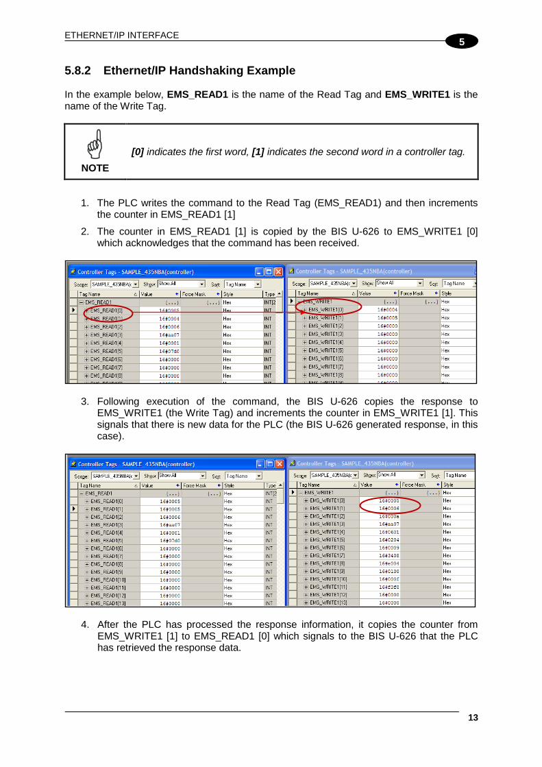
5.8.2 Ethernet/IP Handshaking Example In the example below, EMS_READ1 is the name of the Read Tag and EMS_WRITE1 is the name of the Write Tag.
NOTE
[0] indicates the first word, [1] indicates the second word in a controller tag.
1. The PLC writes the command to the Read Tag (EMS_READ1) and then increments the counter in EMS_READ1 [1]
2. The counter in EMS_READ1 [1] is copied by the BIS U-626 to EMS_WRITE1 [0] which acknowledges that the command has been received.
3. Following execution of the command, the BIS U-626 copies the response to
EMS_WRITE1 (the Write Tag) and increments the counter in EMS_WRITE1 [1]. This signals that there is new data for the PLC (the BIS U-626 generated response, in this case).
4. After the PLC has processed the response information, it copies the counter from
EMS_WRITE1 [1] to EMS_READ1 [0] which signals to the BIS U-626 that the PLC has retrieved the response data.

BIS U-62_ MANUAL
14
5
5. The data will then be cleared from EMS_WRITE1. After which the BIS U-626 will be ready to receive another command.
5.9 ETHERNET/IP: OBJECT MODEL The Object Model is the logical organization of attributes (parameters) within classes (objects) and services supported by each device. Objects are broken down into three categories: Required Objects, Vendor Specific Objects and Application Objects.
• Required Objects are classes that must be supported by all devices on EtherNet/IP. The BIS U-626 has six Required Objects.
• Vendor Specific Objects are classes that add attributes and services that do not fit into the Required Objects or Application Objects categories. The BIS U-626 has two Vendor Specific Objects.
• Application Objects are classes that must be supported by all devices using the same profile. An example of a profile is a Discrete I/O device or an AC Drive. This ensures that all devices with the same profile have a common look on the network.
Data Type Definition Table EtherNet/IP was designed by the Open Device Vendors Association (ODVA) as an open protocol. The following table contains a description of the data types used by ODVA that are also found in this chapter. Data Type Description USINT Unsigned Short Integer (8-bit) UINT Unsigned Integer (16-bit) UDINT Unsigned Double Integer (32-bit) STRING Character String (1 byte per character) BYTE Bit String (8-bits) WORD Bit String (16-bits) DWORD Bit String (32-bits)

ETHERNET/IP INTERFACE
15
5
5.9.1 Ethernet/IP Required Objects Under Ethernet/IP, there are six Required Objects:
• Identity Object (0x01)
• Message Router Object (0x02)
• Assembly Object (0x04)
• Connection Manager Object (0x06)
• TCP Object (0xF5)
• Ethernet Link Object (0xF6) Identity Object (0x01 - 1 Instance) Class Attributes Attribute ID Name / Description Data Type Default Data
Value Access Rule
1 Revision UINT 1 Get Instance Attributes Attribute ID Name / Description Data Type Default Data
Value Access Rule
1 Vendor Number UINT 50 DEC Get 2 Device Type UINT 0x0C Get 3 Product Code Number UINT 6102 DEC Get
4 Product Major Revision Product Minor Revision
USINT USINT
01 25 Get
5 Status Word (see below for definition) WORD See Below Get
6 Serial Number UDINT Unique 32 Bit Value Get
7 Product Name: Product Name Size Product Name String
USINT USINT[26]
UHF-CNTL-IND-x2 06 “Cobalt”
Get
Status Word Bit Bit = 0 Bit = 1 0 No I/O Connection I/O Connection Allocated 1 – 15 Unused Unused
Common Services
Service Code
Implementation Service Name Class Level Instance Level
0x0E Yes Yes Get Attribute Single 0x05 No Yes Reset

BIS U-62_ MANUAL
16
5
Message Router Object (0x02) This object has no supported attributes. Assembly Object (0x04 - 3 Instances) Class Attributes
Attribute ID Name / Description Data Type
Default Data Value
Access Rule
1 Revision UINT 1 Get 2 Max Instance UINT 81 Get
Instance 0x64 Attributes (Input Instance)
Attribute ID Name / Description Data Type
Default Data Value
Access Rule
3 Status Information:
Get Bitmap of Consume Instances with Data DINT 0 Bitmap of Produce Instances with Data DINT 0
User Datagram Protocol (UDP) I/O Sequence Number Handshaking The data producing device increments the data sequence number by one with the transmission of each new serial data packet. Valid sequence numbers are 1-65535. After the consuming device has processed the data, it must echo the sequence number in the handshake to allow the producing device to remove the data from the queue. This is required for I/O communications because UDP is not guaranteed to arrive in order. If the Node ID number is passed as part of the I/O message, the message is stored to the appropriate location in the Modbus RTU table. Because communications are asynchronous, the Node ID number is also stored as part of the output data. It is the responsibility of the PLC programmer to make sure the proper request lines up with the proper response if the BIS U-626 is used as a request/response device. Instance 0x65 Attributes (Input Instance 2) Attribute ID Name / Description Data Type Default Data
Value Access Rule
3
Serial Produce Data:
Get
Consume Data Seq. Number Handshake UINT 0
Produce Data Sequence Number UINT 0
Node 1 Serial Produce Data Size UINT 0
Node 1 Serial Produce Data WORD[100] All 0’s

ETHERNET/IP INTERFACE
17
5
Instance 0x66 Attributes (Input Instance 3)
Attribute ID Name / Description Data Type
Default Data Value
Access Rule
3
Serial Produce Data:
Get
Consume Data Seq. Number Handshake UINT 0
Produce Data Sequence Number UINT 0 Node ID (1-32) UINT 1 Node Serial Produce Data Size UINT 0 Node Serial Produce Data WORD[100] All 0’s
Instance 0x70 Attributes (Output Instance 1)
Attribute ID Name / Description Data Type
Default Data Value
Access Rule
3
Serial Consume Data:
Get / Set
Produce Data Seq. Number Handshake UINT 0
Consume Data Sequence Number UINT 0 Node 1 Serial Consume Data Size UINT 0 Node 1 Serial Consume Data WORD[100] All 0’s
Instance 0x71 Attributes (Output Instance 2)
Attribute ID Name / Description Data Type
Default Data Value
Access Rule
3
Serial Consume Data:
Get / Set
Produce Data Seq. Number Handshake UINT 0
Consume Data Sequence Number UINT 0 Node ID (1-32) UINT 1 Node Serial Consume Data Size UINT 0 Node Serial Consume Data WORD[100] All 0’s
Instance 0x80 Attributes (Configuration Instance) Most I/O clients include a configuration path when opening an I/O connection to a server. There is no configuration data needed. Instance 0x81 Attributes (Heartbeat Instance – Input Only) This instance allows clients to monitor input data without providing output data. Common Services
Service Code
Implementation Service Name Class Level Instance Level 0x0E Yes Yes Get Attribute Single 0x10 No Yes Set Attribute Single

BIS U-62_ MANUAL
18
5
Connection Manager Object (0x06) This object has no attributes. TCP Object (0xF5 - 1 Instance) Class Attributes
Attribute ID Name / Description Data Type
Default Data Value
Access Rule
1 Revision UINT 1 Get Instance Attributes
Attribute ID Name / Description Data Type
Default Data Value
Access Rule
1 Status* DWORD 1 Get 2 Configuration Capability* DWORD 0 Get 3 Configuration Control* DWORD 0 Get
4 Physical Link Object* Structure of: Path Size Path
UINT Array Of WORD
2 0x20F6 0x2401
Get
5
Interface Configuration*
Structure of: IP Address Network Mask Gateway Address Name Server Name Server 2 Domain Name Size Domain Name
UDINT UDINT UDINT UDINT UDINT UINT STRING
0 0 0 0 0 0 0
Get
6 Host Name*
Structure of: Host Name Size Host Name
UINT STRING
0 0
Get
*See section 5-3.2.2.1 – 5-3.2.2.6 of “Volume 2: EtherNet/IP Adaptation of CIP” from ODVA for more information regarding these attributes. Common Services
Service Code
Implementation Service Name Class Level Instance Level 0x0E Yes Yes Get Attribute Single

ETHERNET/IP INTERFACE
19
5
Ethernet Link Object (0xF6 - 1 Instance) Class Attributes
Attribute ID Name / Description Data Type Default Data Value
Access Rule
1 Revision UINT 1 Get Instance Attributes
Attribute ID Name / Description Data Type Default Data Value
Access Rule
1 Interface Speed* UDINT 100 Get 2 Interface Flags* DWORD 3 Get
3 Physical Address* USINT Array[6] 0 Get
*See section 5-4.2.2.1 – 5-4.2.2.3 of “Volume 2: EtherNet/IP Adaptation of CIP” from ODVA for more details on this attribute. Common Services
Service Code
Implementation Service Name Class Level Instance Level 0x0E Yes Yes Get Attribute Single
5.9.2 EtherNet/IP: Vendor Specific Objects The BIS U-626 has two Vendor Specific Objects: Vendor Specific Objects: BIS U-626 Consume Data Object (0x64) BIS U-626 Produce Data Object (0x65) BIS U-626 CONSUME DATA OBJECT (0X64 - 32 INSTANCES) Class Attributes (Instance 0)
Attribute ID Name / Description Data Type
Default Data Value
Access Rule
1 Revision UINT 1 Get
2 Maximum Consume Data Buffer Size (in words) UINT 32768 Get
3 Bitmap of Consume Instances with Data Bit 0: Instance 1 … Bit 31: Instance 32
DINT 0 Get

BIS U-62_ MANUAL
20
5
Instance Attributes (Instances 1-32)
Attribute ID Name / Description Data Type
Default Data Value
Access Rule
1 Consume Data Size (in words) UINT 0 Get / Set 2 Consume Data [0-249] UINT 0 Get / Set 3 Consume Data [250-499] UINT 0 Get / Set 4 Consume Data [500-749] UINT 0 Get / Set 5 Consume Data [750-999] UINT 0 Get / Set 6 Consume Data [1,000-1,249] UINT 0 Get / Set … … … … … 10 Consume Data [2,000-2,249] UINT 0 Get / Set … … … … … 34 Consume Data [8,000-8,249] UINT 0 Get / Set … … … … … 38 Consume Data [9,000-9,249] UINT 0 Get / Set … … … … … 42 Consume Data [10,000-10,249] UINT 0 Get / Set … … … … … 82 Consume Data [20,000-20,249] UINT 0 Get / Set … … … … … 122 Consume Data [30,000-30,249] UINT 0 Get / Set … … … … … 126 Consume Data [31,000-31,249] UINT 0 Get / Set … … … … … 130 Consume Data [32,000-32,249] UINT 0 Get / Set 131 Consume Data [32,250-32,249] UINT 0 Get / Set 132 Consume Data [32,500-32,249] UINT 0 Get / Set 133 Consume Data [32,750-32,767] UINT 0 Get / Set
Common Services
Service Code
Implementation Service Name Class Level Instance Level 0x05 No Yes Reset* 0x0E Yes Yes Get Attribute Single 0x10 No Yes Set Attribute Single
*This Service Code is used to flush all attributes to zero.

ETHERNET/IP INTERFACE
21
5
BIS U-626 Produce Data Object (0x65 - 32 Instances) Class Attributes (Instance 0)
Attribute ID Name / Description Data Type
Default Data Value
Access Rule
1 Revision UINT 1 Get
2 Maximum Produce Data Buffer Size (in words) UINT 32768 Get
3 Bitmap of Produce Instances with Data Bit 0: Instance 1 … Bit 31: Instance 32 DINT 0 Get
Instance Attributes (Instances 1-32)
Attribute ID Name / Description Data Type
Default Data Value
Access Rule
1 Produce Data Size (in words) UINT 0 Get / Set
2 Produce Data [0-249] UINT 0 Get 3 Produce Data [250-499] UINT 0 Get 4 Produce Data [500-749] UINT 0 Get 5 Produce Data [750-999] UINT 0 Get 6 Produce Data [1,000-1,249] UINT 0 Get … … … … … 10 Produce Data [2,000-2,249] UINT 0 Get … … … … … 34 Produce Data [8,000-8,249] UINT 0 Get … … … … … 38 Produce Data [9,000-9,249] UINT 0 Get … … … … … 42 Produce Data [10,000-10,249] UINT 0 Get … … … … … 82 Produce Data [20,000-20,249] UINT 0 Get … … … … … 122 Produce Data [30,000-30,249] UINT 0 Get … … … … … 126 Produce Data [31,000-31,249] UINT 0 Get … … … … … 130 Produce Data [32,000-32,249] UINT 0 Get 131 Produce Data [32,250-32,249] UINT 0 Get 132 Produce Data [32,500-32,249] UINT 0 Get 133 Produce Data [32,750-32,767] UINT 0 Get

BIS U-62_ MANUAL
22
5
Common Services
Service Code
Implementation Service Name Class Level Instance Level 0x05 No Yes Reset* 0x0E Yes Yes Get Attribute Single 0x10 No Yes Set Attribute Single
*This Service Code is used to flush all attributes to zero. 5.9.3 Application Object (0x67 – 10 Instances) Class Attributes (Instance 0) Attribute ID Name / Description Data Type Default Data
Value Access Rule
1 Revision UINT 1 Get Instance Attributes (Instances 1-32) Attribute ID Name / Description Data Type Default Data
Value Access Rule
1
Instance Type (0-3): 0 - Disable 1 – ControlLogix 2 – SLC 5/05 3 – PLC5E
USINT 0 Get
2 PLC IP Address UDINT 0 Get
3 PLC Slot Location (0-255) USINT 0 Get
11 Max Write Size in Words: 0 – Disabled 1 – 100 Words
UINT 0 Get
12 Write Tag Name (ControlLogix Only)
SHORT STRING 0 Get
13 Write File Number (SLC/PLC Only) NX:0 - where “X” is the File Number
UINT 7 Get
14 Write File Offset (SLC/PLC Only) N7:Y - where “Y” is the File Offset
UINT 0 Get
15
Write “Heartbeat” Timeout Measured in 10ms “ticks” 0 = disabled Max value: 6000 ticks
UINT 100 Get
21 Max Read Size in Words 0 – Disable Max Value: 100
UINT 0 Get
22 Read Tag Name (ControlLogix Only)
SHORT STRING 0 Get
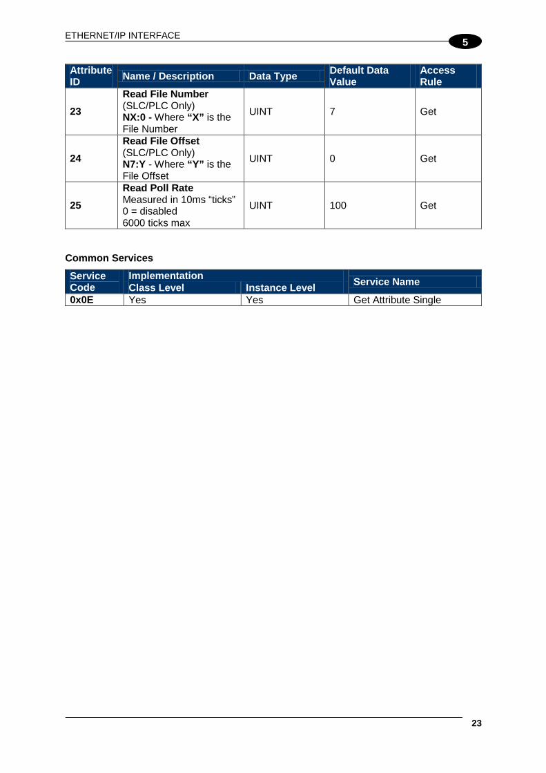
ETHERNET/IP INTERFACE
23
5
Attribute ID Name / Description Data Type Default Data
Value Access Rule
23 Read File Number (SLC/PLC Only) NX:0 - Where “X” is the File Number
UINT 7 Get
24 Read File Offset (SLC/PLC Only) N7:Y - Where “Y” is the File Offset
UINT 0 Get
25 Read Poll Rate Measured in 10ms “ticks” 0 = disabled 6000 ticks max
UINT 100 Get
Common Services
Service Code
Implementation Service Name Class Level Instance Level 0x0E Yes Yes Get Attribute Single

BIS U-62_ MANUAL
24
5
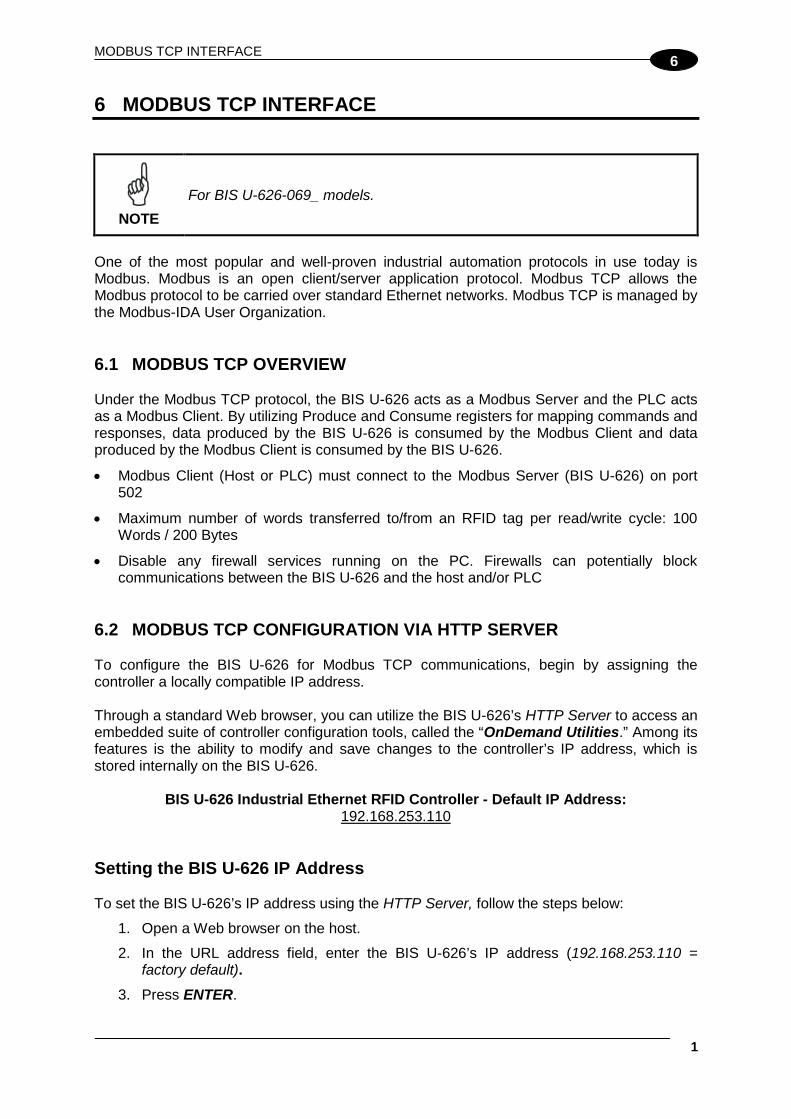
MODBUS TCP INTERFACE
1
6
6 MODBUS TCP INTERFACE
NOTE
For BIS U-626-069_ models.
One of the most popular and well-proven industrial automation protocols in use today is Modbus. Modbus is an open client/server application protocol. Modbus TCP allows the Modbus protocol to be carried over standard Ethernet networks. Modbus TCP is managed by the Modbus-IDA User Organization. 6.1 MODBUS TCP OVERVIEW Under the Modbus TCP protocol, the BIS U-626 acts as a Modbus Server and the PLC acts as a Modbus Client. By utilizing Produce and Consume registers for mapping commands and responses, data produced by the BIS U-626 is consumed by the Modbus Client and data produced by the Modbus Client is consumed by the BIS U-626.
• Modbus Client (Host or PLC) must connect to the Modbus Server (BIS U-626) on port 502
• Maximum number of words transferred to/from an RFID tag per read/write cycle: 100 Words / 200 Bytes
• Disable any firewall services running on the PC. Firewalls can potentially block communications between the BIS U-626 and the host and/or PLC
6.2 MODBUS TCP CONFIGURATION VIA HTTP SERVER To configure the BIS U-626 for Modbus TCP communications, begin by assigning the controller a locally compatible IP address. Through a standard Web browser, you can utilize the BIS U-626’s HTTP Server to access an embedded suite of controller configuration tools, called the “OnDemand Utilities.” Among its features is the ability to modify and save changes to the controller’s IP address, which is stored internally on the BIS U-626.
BIS U-626 Industrial Ethernet RFID Controller - Default IP Address: 192.168.253.110
Setting the BIS U-626 IP Address To set the BIS U-626’s IP address using the HTTP Server, follow the steps below:
1. Open a Web browser on the host.
2. In the URL address field, enter the BIS U-626’s IP address (192.168.253.110 = factory default).
3. Press ENTER.

BIS U-62_ MANUAL
2
6
The HTTP Server - Main Page will be displayed.

MODBUS TCP INTERFACE
3
6
HTTP Server – Main Page
Figure 35 - The HTTP Server - Main Page
The HTTP Server - Main Page lists the network settings (including the IP address) currently stored on the BIS U-626.
4. Click the button labeled “EDIT”, located below “Network Settings.”
The IP Configuration Page will be displayed.

BIS U-62_ MANUAL
4
6
IP Configuration Page The IP Configuration Page is used to modify and save changes to the IP Address, Subnet Mask and (Network) Gateway IP Address.
Figure 36 - The IP Configuration Page
5. In the fields provided, enter your new IP configuration values for the BIS U-626.
6. Click the “Save Settings” button to store your new IP configuration, then cycle power to the controller to store the changes in the main memory. The Ethernet module will reset and your IP changes will be implemented.
7. After the BIS U-626 has restarted, verify the new IP configuration by opening a Web browser and manually entering the BIS U-626’s new IP address in the URL field. If successful, you should arrive back at the HTTP Server – Main Page.

MODBUS TCP INTERFACE
5
6
6.2.1 Modbus TCP - Command Packet Structure Consume Registers hold data that is destined for the BIS U-626. Modbus TCP commands must be placed in the holding registers, starting at address 40001, of Device ID 01 (Node Input Page 01). Commands utilize at least six registers (double-byte values or words). Modbus Address (4xxxx / 3xxxx)
Read / Write Privilege Register Description
(40001) 1 R/W 2-byte Consume Data Overall Length (> 0 indicates data is available; BIS U-626 clears to 0 after data is processed)
2 R/W MSB = Reader Type LSB = Command ID
3 R/W MSB = 0x00 LSB = Node ID (0x01 for the BIS U-626)
4 R/W 2-byte Timeout Value (0-65535) measured in milliseconds
5 R/W 2-byte Start Address (0-65535)
6 R/W 2-byte Read/Block Size (0-65535 bytes)
7 – 32774 R/W BIS U-626 Consume Data (when applicable) 32775 – 65536 R/W Reserved
6.2.2 Modbus TCP - Response Packet Structure Produce Registers hold data that is destined for the host or PLC. Modbus Address (4xxxx / 3xxxx)
Read / Write Privilege Register Description
(40001) 1 R/W 2-byte Produce Data Overall Length (> 0 indicates data is available; Modbus Client clears to 0 after data is processed)
2 RO MSB = Reader Type LSB = Command Echo
3 RO Node ID Number (33 for the BIS U-626) 4 RO Timeout Value (0-65535) 5 RO Read/Write Start Address (0-65535) 6 RO Read/Block Size (0-65535 bytes) 7 – 32774 RO BIS U-626 Produce Data (when applicable) 32775 – 65536 RO Reserved

BIS U-62_ MANUAL
6
6
6.2.3 Modbus TCP - Mapping for Node 33 Modbus Address (4xxxx)
Read / Write Privilege Register Description
1 R/W IP Address 1 (MSB) Example: 192 2 R/W IP Address 2 Example: 168 3 R/W IP Address 3 Example: 000 4 R/W IP Address 4 (LSB) Example: 100 5 R/W Subnet Mask 1 (MSB) Example: 255 6 R/W Subnet Mask 2 Example: 255 7 R/W Subnet Mask 3 Example: 255 8 R/W Subnet Mask 4 (LSB) Example: 000 9 R/W Gateway Address 1 (MSB) Example: 192 10 R/W Gateway Address 2 Example: 168 11 R/W Gateway Address 3 Example: 000 12 R/W Gateway Address 4 (LSB) Example: 001 13 RO MAC Address 1 (MSB) Example: 0x00 14 RO MAC Address 2 Example: 0x40 15 RO MAC Address 3 Example: 0x9D 16 RO MAC Address 4 Example: 0x12 17 RO MAC Address 5 Example: 0x34 18 RO MAC Address 6 (LSB) Example: 0x56
19 RO Link Status: 0 = No Link 1 = Link is OK
20 RO Ethernet Speed (10M or 100M bits)
21 RO Link Duplex: 0 = Half Duplex 1 = Full Duplex
22 RO Revision (Major/Minor) 23 – 1000 R/W Reserved 1001 RO (Input) Data Ready Mask - Nodes 1 - 16 1002 RO (Input) Data Ready Mask - Nodes 17 - 32 1003 RO (Output) Data Ready Mask - Nodes 33 - 48 1004 RO (Output) Data Ready Mask - Nodes 49 - 64 1005-10099 R/W Reserved 10100 – 10199 R/W Reserved 10200 – 10299 R/W Reserved … … … 13100 – 13199 R/W Reserved 13200 – 13299 R/W Reserved 13300 – 65536 R/W Reserved

MODBUS TCP INTERFACE
7
6
6.3 MODBUS TCP - HANDSHAKING Due to the process with which commands and responses are passed between the BIS U-626 and the host, a handshaking procedure is used to notify the host that returning data is available for retrieval. Overall Length The handshaking process is governed by the changing of the “Overall Length” value within a data packet. The Overall Length value is typically the first word (2-bytes) of a command or response and indicates the total number of data words in the packet. Node Input and Node Output Pages Under the Modbus TCP protocol, host-generated data is written to a pre-defined region of the BIS U-626’s own memory known as the Node Input Page. Host-bound data generated by the BIS U-626, is written to a separate region of the BIS U-626’s memory known as the Node Output Page (in Modbus TCP these regions of memory are called Device IDs). Node Input and Node Output Pages are used to temporarily hold incoming (controller-bound) and outgoing (host-bound) data. Output Data Ready Mask To notify the host that new data is waiting to be retrieved from the Node Output Page, the BIS U-626 utilizes a separate 32-bit block of internal memory, called the Output Data Ready Mask. The first bit of the 32-bit Output Data Ready Mask represents the status of the Node Output Page. For example, the first or lowest bit (bit 01) represents Node Output Page 33 - which holds output data from Node 01. The BIS U-626, itself, is assigned Node 01 and thus, its corresponding Node Output Page is 33. As noted, Node Output Page 33 is represented by the first bit (bit 01) in the Output Data Ready Mask. Holding Registers When writing host-bound data to Node Output Page 33, the BIS U-626 actually places each byte of the data packet into pre-defined “holding registers” within the Node Output Page. Note that a single holding register stores 2-bytes or one word of data. The 2-byte Overall Length value, for example, is written to the first holding register (which is location 40001) of the Node Output Page. Then, as the BIS U-626 finishes writing host-bound data to the Node Output Page, the Overall Length value (stored at holding register 40001) will change from its default value of 0x00 to reflect the number of data words within the newly written host-bound data packet. This change to the Overall Length value (i.e. register 40001) within the Node Output Page, triggers the BIS U-626 to enable (change from zero to one) bit one in the Output Data Ready Mask. It is when bit one in the Output Data Ready Mask has become enabled, that the host will recognize the pending data. Finally, after the host has retrieved its pending data, the enabled bit in the Output Data Ready Mask and the Overall Length value at holding register 40001 of the Node Output
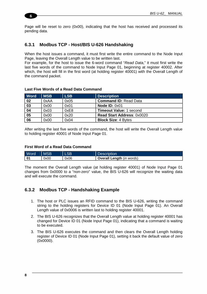
BIS U-62_ MANUAL
8
6
Page will be reset to zero (0x00), indicating that the host has received and processed its pending data. 6.3.1 Modbus TCP - Host/BIS U-626 Handshaking When the host issues a command, it must first write the entire command to the Node Input Page, leaving the Overall Length value to be written last. For example, for the host to issue the 6-word command “Read Data,” it must first write the last five words of the command to Node Input Page 01, beginning at register 40002. After which, the host will fill in the first word (at holding register 40001) with the Overall Length of the command packet. Last Five Words of a Read Data Command
Word MSB LSB Description 02 0xAA 0x05 Command ID: Read Data 03 0x00 0x01 Node ID: 0x01 04 0x03 0xE8 Timeout Value: 1 second 05 0x00 0x20 Read Start Address: 0x0020 06 0x00 0x04 Block Size: 4 Bytes
After writing the last five words of the command, the host will write the Overall Length value to holding register 40001 of Node Input Page 01. First Word of a Read Data Command
Word MSB LSB Description 01 0x00 0x06 Overall Length (in words)
The moment the Overall Length value (at holding register 40001) of Node Input Page 01 changes from 0x0000 to a “non-zero” value, the BIS U-626 will recognize the waiting data and will execute the command. 6.3.2 Modbus TCP - Handshaking Example
1. The host or PLC issues an RFID command to the BIS U-626, writing the command string to the holding registers for Device ID 01 (Node Input Page 01). An Overall Length value of 0x0006 is written last to holding register 40001.
2. The BIS U-626 recognizes that the Overall Length value at holding register 40001 has changed for Device ID 01 (Node Input Page 01), indicating that a command is waiting to be executed.
3. The BIS U-626 executes the command and then clears the Overall Length holding register of Device ID 01 (Node Input Page 01), setting it back the default value of zero (0x0000).
MODBUS TCP INTERFACE
9
6
NOTE
NOTE: when the Node Input Page’s value at register 40001 is returned to 0x0000, the host can assume that the command was at least received and execution was attempted. The host can also assume that it is OK to clear the remaining holding registers and write another command to the Device ID (Node Input Page).
4. After the BIS U-626 executes its given command instructions, it will write the
command response to the holding registers for Device ID 33 (Node Output Page 33). Again, the Overall Length value is written last to holding register 40001.
NOTE
Host-bound data is always written to Device ID 33 (Node Output Page 33).
5. With holding register 40001 of Device ID 33 (Node Output Page 33) now containing a non-zero length value, the BIS U-626 will enable (change from zero to 1) the first bit in the Output Data Ready Mask. (The first bit is allocated to Node Output Page 33).
6. Once bit 01 in the Output Data Ready Mask becomes enabled, the host retrieves the data string stored in the holding register area for Device ID 33 (Node Output Page 33).
7. After importing the data from Device ID 33 (Node Output Page 33), the host clears (sets back to 0x0000) the Overall Length value at holding register 40001 of Device ID 33 (Node Output Page 33). In doing so, bit 01 in the Output Data Ready Mask is also cleared.
NOTE
The clearing of bit 01 in the Output Data Ready Mask indicates to the BIS U-626 that the host has received the response and that it is now OK to write another response to Node Output Page 33.
This completes the Modbus TCP handshaking cycle.

BIS U-62_ MANUAL
10
6

STANDARD TCP/IP INTERFACE
1
7
7 STANDARD TCP/IP INTERFACE
NOTE
For BIS U-626-069_ models.
7.1 STANDARD TCP/IP OVERVIEW Another means of communicating with the BIS U-626 is through the standard TCP/IP protocol. For this manual, the protocol is referred to as Standard TCP/IP to distinguish it from other industrial protocols. In this environment, the BIS U-626 acts as the server and the host or PLC acts as client. Standard TCP/IP sessions are established between the host computer and the BIS U-626 via TCP/IP client software. A TCP/IP session generally consists of three stages: connection setup, data transactions and connection termination. All connections to the BIS U-626 are initiated by client side software only. If, for example, an existing connection terminates unexpectedly, the BIS U-626 will not attempt to contact the client software or re-establish a connection. The client is responsible for opening, maintaining, and closing all TCP/IP sessions. After establishing a successful connection, communications between the host and the BIS U-626 can proceed. When communication is no longer necessary, it is the responsibility of the client side application to terminate the connection.
• The TCP/IP client software (running on the host or PLC) must connect to the TCP/IP server (BIS U-626) on port 2101
• Maximum number of words transferred to/from an RFID tag per read/write cycle: 100 Words / 200 Bytes
• Disable any firewall services running on the PC. Firewalls can potentially block communications between the BIS U-626 and the host and/or PLC
7.2 STANDARD TCP/IP - IP CONFIGURATION VIA HTTP SERVER To configure the BIS U-626 for standard TCP/IP communications, begin by assigning the processor units a locally compatible IP address. Through a standard Web browser, you can utilize the BIS U-626’s HTTP Server to access an embedded suite of processor units configuration tools, called the “OnDemand Utilities.” Among its features is the ability to modify and save changes to the processor units’s IP address, which is stored internally on the BIS U-626.
BIS U-626 Industrial Ethernet RFID Processor units Default IP Address: 192.168.253.110

BIS U-62_ MANUAL
2
7
Setting the BIS U-626 IP Address To set the BIS U-626’s IP address using the HTTP Server, follow the steps below:
1. Open a Web browser on the PC.
2. In the URL address field, enter the BIS U-626’s IP address (192.168.253.110 = factory default).
3. Press ENTER. The HTTP Server - Main Page will be displayed.
Figure 37 - The HTTP Server - Main Page
The HTTP Server - Main Page lists the network settings (including the IP address) currently stored on the BIS U-626.
4. Click the button labeled “EDIT”, located below “Network Settings.”
The IP Configuration Page will be displayed.

STANDARD TCP/IP INTERFACE
3
7
IP Configuration Page The IP Configuration Page is used to modify and save changes to the IP Address, Subnet Mask and (Network) Gateway IP Address.
Figure 38 - The IP Configuration Page
5. In the fields provided, enter your new IP configuration values for the BIS U-626.
6. Click the “Save Settings” button to store your new IP configuration. The BIS U-626 will completely reset and your IP changes will be implemented.
7. After the BIS U-626 has restarted, verify the new IP configuration by opening a Web browser and manually entering the BIS U-626’s new IP address in the URL field. If successful, you should arrive back at the HTTP Server – Main Page.

BIS U-62_ MANUAL
4
7
7.3 STANDARD TCP/IP - COMMAND & RESPONSE EXAMPLES In standard TCP/IP, RFID commands issued by the host resemble Modbus TCP commands. The BIS U-626 handles all handshaking tasks. Moreover, the command & response packets need an additional word at the beginning of the string:
Protocol Header 0xFF in MSB, <Node ID> in LSB. Please notice that these two bytes are not considered part of the CBx command packet and should not be counted in the Overall Length. Below is the structure of the additional word required, named as Word # 00: Word # Command Packet Element MSB LSB
00 Protocol Header in MSB: 0xFF Node ID in LSB 0xFF <Node ID>
And similarly for the response: Word # Response PACKET ELEMENT MSB LSB
00 Protocol Header in MSB: 0xFF Node ID Echo in LSB 0xFF <Node ID Echo>
NOTE
These first two bytes will not be returned in the response packet for commands executed by Node 01.
Therefore, the command packet structure for Standard TCP/IP applications is:
Figure 39 - Standard TCP/IP Protocol Command Packet Structure

STANDARD TCP/IP INTERFACE
5
7
7.3.1 Standard TCP/IP - Command Structure Example In the following example, a 12-byte command has been issued to the BIS U-626, instructing the processor units to read six bytes from a tag within RF range. A Timeout Value of five seconds has been set for the completion of the command. Word Description MSB LSB
00 Protocol Header in MSB = 0xFF Node ID in LSB = default value for BIS U-626 is one (0x01)
0xFF 0x01
01 Overall Length: 2-byte integer indicating number of “words” in the command packet 0x00 0x06
02 MSB = 0xAA LSB = Command ID: (example: 0x05 – Read Data) 0xAA 0x05
03 MSB = 0x00 LSB = Node ID: default value for BIS U-626 is one (0x01)
0x00 0x01
04 Timeout Value: 2-byte integer measured in .10 (1/10th) second increments. (0x0032 = 50 x .10 or 5 seconds)
0x00 0x32
05 Start Address: 2-byte integer identifies tag address where read will begin 0x00 0x01
06 Block Size: 2-byte integer indicates number of bytes to retrieve 0x00 0x06
7.3.2 Standard TCP/IP - Response Structure Example The following resembles a typical response to the command issued in the previous example: Word Description MSB LSB
00 Protocol Header in MSB = 0xFF Node ID in LSB = default value for BIS U-626 is one (0x01)
0xFF 0x01
01 Overall Length: 2-byte integer indicating number of “words” in the response packet 0x00 0x09
02 MSB = 0xAA LSB = Command Echo: (0x05 - Read Data) 0xAA 0x05
03 MSB = Instance Counter LSB = Node ID: 0x01 <IC> 0x01
04 Time Stamp: Month / Day (March 19th) 0x03 0x13 05 Time Stamp: Hour / Minute (8:15 a.m.) 0x08 0x0E
06 MSB = Time Stamp: Seconds LSB = Number of Additional Bytes Retrieved: 6 0x00 0x06
07 Retrieved Bytes 1 & 2 0x61 0x62 08 Retrieved Bytes 3 & 4 0x63 0x64 09 Retrieved Bytes 5 & 6 0x65 0x66

BIS U-62_ MANUAL
6
7

TECHNICAL FEATURES
1
8
8 TECHNICAL FEATURES 8.1 BIS U-62_ PROCESSOR UNIT
ELECTRICAL FEATURES Supply Voltage 12 to 30 VDC DC Input Current max. 600 to 270 mA Host Communication Interface:
RS232 Baud Rate
RS232 9600 (default) to 115200
RS485 Baud Rate
Subnet16™ (RS485) 9600 (default) to 115200
IND Baud Rate
Ethernet IP, TCP/IP, MODBUS TCP 10/100 Mbps
RADIO FEATURES EU US Frequency (MHz)
ETSI EN 302 208 865 to 868 - FCC part 15.247 - 902 to 928
Number of Channels 4 fixed 50 hopping Frequency Tolerance ± 10 ppm over entire temp range Air Interface EPC C1G2 Conducted Output Power 500 mW (27 dBm) max Antenna Connector Reverse TNC ENVIRONMENTAL FEATURES Operating Temperature -20° to +50 °C (-4° to +122 °F) Storage Temperature -20° to +70 °C (-4° to +158 °F) Humidity max. 90% non condensing Vibration Resistance EN 60068-2-6
14 mm @ 2 to 10 Hz; 1.5 mm @ 13 to 55 Hz;
2 g @ 70 to 200 Hz; 2 hours on each axis
Shock Resistance EN 60068-2-27
30 g; 11 ms; 3 shocks on each axis
Protection Class EN 60529 IP65* PHYSICAL FEATURES Dimensions: 164 x 112 x 48 mm (6.46 x 4.41 x 1.88 in) Weight: 560 g (19.8 oz) Enclosure Powder Coated Aluminum USER INTERFACE LED Indicators:
RS232 READY, RF, COM RS485 READY, RF, COM, NODE ID IND READY, RF, COM, DEFAULT IP, CUSTOM IP
The features given are typical at a 25 °C ambient temperature (if not otherwise indicated).
* When all connectors and antenna are correctly installed.

BIS U-62_ MANUAL
2
8
8.2 HF-SERIES ANTENNAS
RADIO FEATURES EU
BIS U-301-C0-TNCB BIS U-302-C0-TNCB
US BIS U-301-C1-TNCB BIS U-302-C1-TNCB
Frequency Range (MHz) ETSI EN 302 208 865 to 868 - FCC part 15 - 902 to 928
Gain 5.5 dBic 8.4 dBic
5.5 dBic 8.4 dBic
3 dB Beamwidth (typical) 100° 70°
100° 70°
Polarization RHCP Input Impedance 50 ohms Input Power 6 W max Antenna Connector N Type Female ENVIRONMENTAL FEATURES Operating Temperature -25° to +55 °C (-13° to +131 °F) Storage Temperature -25° to +70 °C (-13° to +158 °F)
Vibration Resistance EN 60068-2-6
14 mm @ 2 to 10 Hz; 1.5 mm @ 13 to 55 Hz;
2 g @ 70 to 200 Hz; 2 hours on each axis
Shock Resistance EN 60068-2-27
30 g; 11 ms; 3 shocks on each axis
Humidity max. 90% non condensing Protection Class EN 60529 IP65 (when correctly mounted) PHYSICAL FEATURES BIS U-301_ Dimensions 133 x 133 x 18.4 mm (5.24 x 5.24 x 0.72 in) Weight 0.365 kg (0.81 lbs) BIS U-302_ Dimensions 271 x 271 x 42.5 mm (10.67 x 10.67 x 1.67 in) Weight 1.7 kg (3.75 lbs)
The BIS U-62_ processor unit and its antenna are intended for indoor use only.

NOME MANUALE/NOME CAPITOLO
1
9
A RFID OVERVIEW RFID OVERVIEW Cobalt UHF-Series products are designed for use with passive RFID tags, which do not require batteries or contain an internal power supply. The tags collect the power necessary to operate from the RF field generated by the reader and through a process called backscattering they can reflect some of this power back to the reader, thus creating a communication channel. When a passive tag comes in contact with the RF field from an RFID antenna, the incoming radio frequency signal generates a small, but sufficient, electrical current that powers the passive tag’s integrated circuit (IC)
When mounting RFID antennas and tags, it is important to understanding certain principles. If your RFID application requires that the tag be attached directly to a metal surface, always use a non-metallic tag spacer to avoid a possible reduction in read/write range. In addition, motors, conveyors and other automation equipment can produce excessive electrical noise that may also negatively affect RF performance. Cobalt UHF-Series products should only be used with well-grounded systems. Conveyor equipment should be tied directly to an earth ground by an electrician. All cables used on or around Cobalt UHF RFID devices must be shielded. Cable shields typically should be grounded at only one end. The majority of the Antenna-to-Tag range results specified in this publication were measured in a free air environment – where no metallic objects were within the antenna’s RF field. Yet because proximity to metals and other environmental conditions can adversely affect read and write range, it is not possible to state absolute range results achieved under all conditions. System integrators should validate the RF performance of the RFID products used and should not rely solely on Datalogic’s published range specifications.

OVERVIEW ON ULTRA HIGH FREQUENCY RFID APPLICATIONS UHF Standards and Regulations One of the most important aspects of a tag and reader coupling is the frequency at which it operates. Frequency of operation can vary based on the application, standards, and regulations. The most common RFID frequency ranges are Low Frequency (LF) at 135kHz or less, High Frequency (HF) at 13.56MHz, Ultra High Frequency (UHF) starting at 300MHz. Microwave Frequency at 2.45GHz and 5.4GHz is also used in some applications. Ultra High Frequency (UHF) designates a range (or band) of electromagnetic waves with frequencies between 300 MHz and 2.45 GHz (2,450 MHz).
Figure 40 - Radiowaves Spectrum Diagram
There are different UHF operating frequency standards all over the world, regulated by governmental authorities in most countries: for instance, Federal Communications Commission (FCC) in the United States and ETSI (European Telecommunications Standards Institute) in Europe. Globally, each country has its own frequency allocation for RFID. For instance, RFID UHF bands are:
865–870 MHz in Europe
902–928 MHz in North and South America
950–956 MHz in Japan and some Asian countries

NOME MANUALE/NOME CAPITOLO
3
9
Figure 41 - Radiofrequency Bands Allocation
With reference to power limits, the maximum allowed reader radiated power is 4 Watts in the US, and 2 Watts in Europe. Region Regulations Radiated Power USA FCC Part 15 4 W EIRP (36 dBm) Europe EN 302 208 2 W ERP (35 dBm)
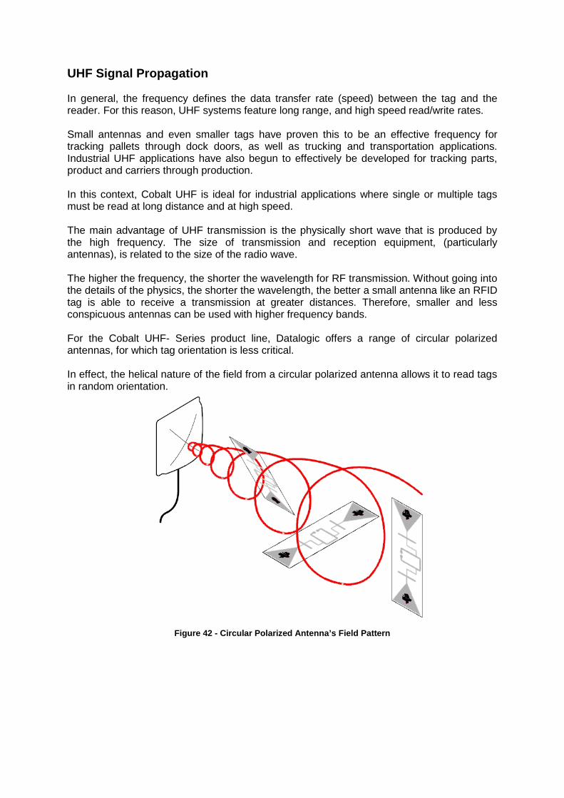
UHF Signal Propagation In general, the frequency defines the data transfer rate (speed) between the tag and the reader. For this reason, UHF systems feature long range, and high speed read/write rates. Small antennas and even smaller tags have proven this to be an effective frequency for tracking pallets through dock doors, as well as trucking and transportation applications. Industrial UHF applications have also begun to effectively be developed for tracking parts, product and carriers through production. In this context, Cobalt UHF is ideal for industrial applications where single or multiple tags must be read at long distance and at high speed. The main advantage of UHF transmission is the physically short wave that is produced by the high frequency. The size of transmission and reception equipment, (particularly antennas), is related to the size of the radio wave. The higher the frequency, the shorter the wavelength for RF transmission. Without going into the details of the physics, the shorter the wavelength, the better a small antenna like an RFID tag is able to receive a transmission at greater distances. Therefore, smaller and less conspicuous antennas can be used with higher frequency bands. For the Cobalt UHF- Series product line, Datalogic offers a range of circular polarized antennas, for which tag orientation is less critical. In effect, the helical nature of the field from a circular polarized antenna allows it to read tags in random orientation.
Figure 42 - Circular Polarized Antenna’s Field Pattern

NOME MANUALE/NOME CAPITOLO
5
9
Furthermore, the Cobalt UHF antennas feature a 3dB Beamwidth, 63° or 65°, providing a large reading zone.
3 dB beam width A B
0.5 0.6 1.0 1.3 1.5 2.0 2.0 2.6 2.5 3.1 3.0 3.7
Figure 43 - Circular Polarized Antenna’s Reading Range
As considered above, the ability for signals to propagate within environment is dependent on the signal wavelength, and hence frequency. UHF will have challenges with crowded environments: within warehouses, truck yards, and other facilities, the ability for an RFID system to operate in and around obstructions is critical. These obstructions are often metallic, such as vehicles and metal shelving racks, requiring signals to propagate “around” rather than “through” the obstructions. For that reason, for industrial applications involving significant environmental obstructions HF is a preferred frequency.

At UHF frequencies, multi-path RF waves caused by reflections from the floor and other obstructions may combine constructively or destructively. When these signals are in-phase they combine to give a stronger signal, but when out-of-phase, they cancel and create "reading holes" that get worse with distance from the antenna.
Figure 44 - RF Wave Reflections
Therefore, referring to the picture above:
• Tags A and D are in strong zones and will read.
• Tag B will read if its antenna is long enough to ‘span the gap’
• Tag C and E will not read All materials reduce the power of the RF signal to some extent, but direct contact on metals and liquids can cause particular problems:
• Metals reflect the signal. A metal object may change the tuning of a tag (or frequency on which it can receive signals), reflecting the RF waves from a reader, or block communication from a specific antenna.
• Liquids (including atmospheric moisture) absorb the signal. All radio waves are partially absorbed by atmospheric moisture. Atmospheric absorption reduces, or attenuates, the strength of radio signals over long distances. In addition, the effects of attenuation increases according to the frequency; thereby, UHF signals are generally more degraded by moisture than lower bands.
Limiting Interference and UHF Signal Attenuation The following hints may be useful to get the best performance from your RFID application. Reading holes can be reduced in a number of ways:
• By removing metal from the reading area: if the reflections can be reduced so will the holes
• By movement of the tag past the antenna: as the tag moves, it will cross the holes and be read at some point. The exact speed is a compromise between the number of tags and the bandwidth of the system. Because of Governmental regulation, for instance, readers are capable of reading more tags in the same time in the USA than is possible in Europe.

NOME MANUALE/NOME CAPITOLO
7
9
Multiple readers operating in the same environment may interfere with one another. A number of techniques can help limit these unwanted effects:
• Use photo-cell triggering to initiate reading - don’t have the reader transmitting all the time
• Reduce the power
• Reduce the downlink rate
• Shield between reading systems with absorptive material (metals could make the problem worse)
Most important, testing should be performed in the actual environment to achieve more precise range results.

Nr.
896
713
E . E
ditio
n 13
08; S
ubje
ct to
mod
ifica
tion.


