28
... non-contact data communication at 13.56 MHz Identification Systems BIS M
| Date post: | 12-Jul-2018 |
| Category: |
Documents |
| Upload: | vuongxuyen |
| View: | 214 times |
| Download: | 0 times |
No.
840
841
E
. E
ditio
n 05
03;
Sub
ject
to
mod
ifica
tion.
... non-contact data communication at 13.56 MHzIdentification Systems BIS M
Go here forfast information!
Balluff GmbHSchurwaldstrasse 973765 Neuhausen a.d.F.GermanyPhone +49 (0) 71 58/1 73-0Fax +49 (0) 71 58/50 10E-Mail: [email protected]
For more Identification Systemsrefer to catalogs for BIS C, BIS Land BIS S, on CD-ROM or online!

Balluff is a world leader inthe field of sensortechnology. Our productrange includes electronicand electromechanicalsensors, transducers andidentification systems,as well as bus-compatiblesensors.
Balluff products are foundwherever precision,reliability, and highest qualityare demanded. Theseindispensible componentsguarantee a successfulinstallation in virtually anyarea of automation.
Whether it's automation,object detection, materialflow control, linear or rotarymotion – Balluff is the rightpartner.
We are DIN ISO 9001certified. Statistical processcontrol, the use of processcontrolled production andassembly equipment arestandard at Balluff.

Identification Systems BIS M
Description
Read/Write System BISM
i.1
i
Modern automationtechnology withoutautomatic identification hasbecome unthinkable. Severalapproaches are available,including bar code labels,mechanical coding,transmitter/receiver systemsusing microwave, orinductive identificationsystems. Gitterbox identification
It's not always easy to makethe right choice. But practicehas shown that inductiveidentification systems areoften the preferred solution,especially in production andassembly technology.
The inductive principleguarantees ruggedness andresistance to ambienteffects, and makes thesenon-contacting systemsextremely reliable andfunction-secure. Use inharsh industrial environmentsis therefore never a problem.
Material and information floware inseparable in computercontrolled assembly andmanufacturing. The consis-tent coupling of these twoflow elements is requiredtoday for flexibility and costeffectiveness in automation.
Series BIS IdentificationSystems ensure a reliableexchange of informationbetween material flow anddata processing, includingall areas of manufacturingwhere materials are beingmoved:– workpiece transport in
conveying systems– FTS and pallet transport
systems– warehousing– assembly– flexible manufacturing
cells and many others
The advantage to you is costreduction through:– flexibility– faster access to
information– shorter response times– stock optimization
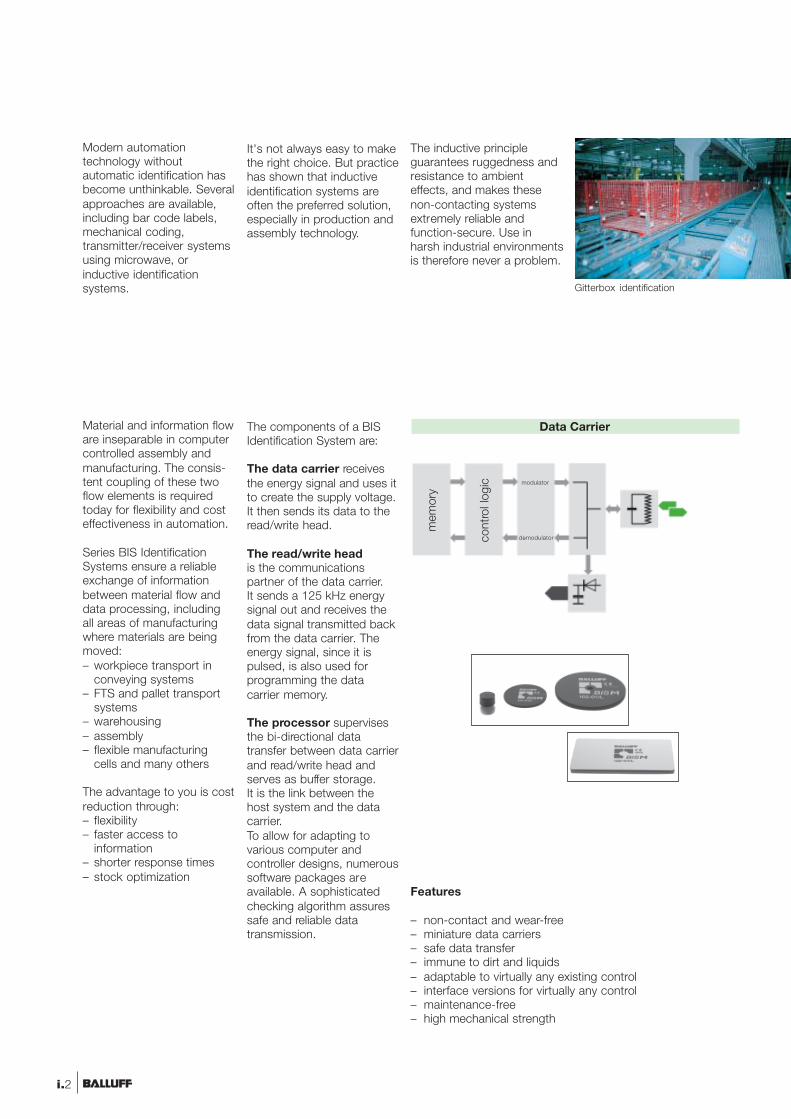
The components of a BISIdentification System are:
The data carrier receivesthe energy signal and uses itto create the supply voltage.It then sends its data to theread/write head.
The read/write headis the communicationspartner of the data carrier.It sends a 125 kHz energysignal out and receives thedata signal transmitted backfrom the data carrier. Theenergy signal, since it ispulsed, is also used forprogramming the datacarrier memory.
The processor supervisesthe bi-directional datatransfer between data carrierand read/write head andserves as buffer storage.It is the link between thehost system and the datacarrier.To allow for adapting tovarious computer andcontroller designs, numeroussoftware packages areavailable. A sophisticatedchecking algorithm assuressafe and reliable datatransmission.
Features
– non-contact and wear-free– miniature data carriers– safe data transfer– immune to dirt and liquids– adaptable to virtually any existing control– interface versions for virtually any control– maintenance-free– high mechanical strength
Data Carrierm
emor
y
cont
rol l
ogic modulator
demodulator
UB
i.2
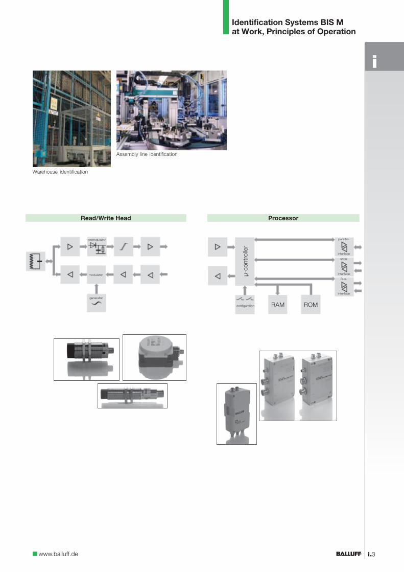
Identification Systems BIS Mat Work, Principles of Operation
Warehouse identification
Assembly line identification
www.balluff.de
Processor
modulator
demodulator
generator
configuration
parallel-
interface
serial
interface
interface
Bus-
µ-co
ntro
ller
RAM ROM
Read/Write Head
i.3
i

Spatial Arrangementof Read/Write Head resp.Read Head and DataCarrier
The key to reliable dataexchange between theread/write head resp.read head and the datacarrier is maintainingsufficent dwell time of thedata carrier within aspecified spatial distancefrom the read/write headresp. read head.The drawing illustrates thisrelationship.
For a static read/writeresp. read operation thedata carrier stops completelyin front of the read/writeresp. read heads; thispermits a greater distancebetween the two.
For dynamic operationthe data carrier is read orprogrammed on the fly. Theshorter distance is necessaryin order to achieve as large aread/write resp. read path aspossible.
Each read/write head orread head has certain datacarrier which can be usedwith it (the pairing is basedon physical size and antennafield configuration).
Spatial arrangement of read/write head resp. read headand data carrier fordirectional read/write heads
data carrier
active zone for readingand writing resp. readingto the data carrierpermissible
offset
resp. read heads (circularantenna).
read/write resp.read head
Identification Systems BIS MThe Relationship betweenRead/Write Heads and Data Carriers
i.4

IdentificationSystems BIS M Contents
M.1
Data carriers
Processors
HostcontrollerPLC, PC
BIS M
Data exchangebetween the datacarrier and read/writehead is non-contactand therefore wear-free.The data andnecessary power forthe data carrier areinductively coupled bythe read/write head.The data carrierrequires no battery foroperation or dataretention. Exactpositioning is notnecessary.Data integrity isensured by means ofspecial checking soft-ware. No additionaldata security measureson the part of the userare required.
M.2 Data CarriersM.4 Read/Write HeadsM.6 Compact Processors
for Simultaneous ModeM.12 Connectors,
Termination ResistorM.18 Installation NotesM.20 Read/Write Times
Software, Service Tools
Data Carriers
Read/WriteHeads
CompactProcessors forSimultaneousMode
Connectors,TerminationResistor
InstallationNotes
Read/WriteTimesSoftware,Service Tools
BISM
INTE
RB
US
PR
OFI
BU
S-D
PD
evic
eNet
TM
INTE
RB
US
PR
OFI
BU
S-D
PD
evic
eNet
TM
Read/write heads
Interfacevariations
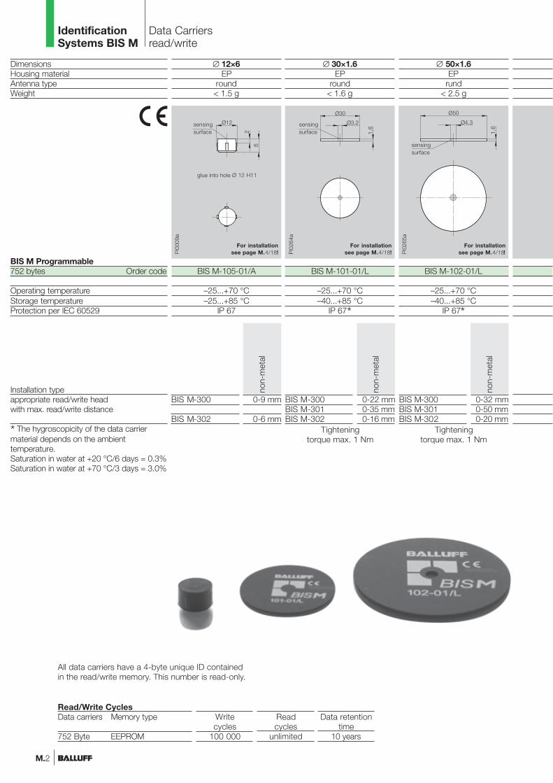
∅ 50×1.6EP
rund< 2.5 g
BIS M-102-01/L
–25...+70 °C–40...+85 °C
IP 67*
∅ 30×1.6EP
round< 1.6 g
BIS M-101-01/L
–25...+70 °C–40...+85 °C
IP 67*
DimensionsHousing materialAntenna typeWeight
BIS M Programmable752 bytes Order code
Operating temperatureStorage temperatureProtection per IEC 60529
Installation typeappropriate read/write headwith max. read/write distance
* The hygroscopicity of the data carriermaterial depends on the ambienttemperature.Saturation in water at +20 °C/6 days = 0.3%Saturation in water at +70 °C/3 days = 3.0%
IdentificationSystems BIS M
Data Carriersread/write
M.2
Data retentiontime
10 years
Readcycles
unlimited
Writecycles
100 000
Read/Write CyclesData carriers Memory type
752 Byte EEPROM
For installationsee page M.4/18!
For installationsee page M.4/18!
sensingsurface
sensingsurface
0-9 mm
0-6 mm
BIS M-300
BIS M-302
non-
met
al
0-22 mm0-35 mm0-16 mm
BIS M-300BIS M-301BIS M-302
non-
met
al
Tighteningtorque max. 1 Nm
0-32 mm0-50 mm0-20 mm
BIS M-300BIS M-301BIS M-302
non-
met
al
Tighteningtorque max. 1 Nm
∅ 12×6EP
round< 1.5 g
BIS M-105-01/A
–25...+70 °C–25...+85 °C
IP 67
For installationsee page M.4/18!
glue into hole Ø 12 H11
sensingsurface
All data carriers have a 4-byte unique ID containedin the read/write memory. This number is read-only.

85.6×54×0.76PVCround
< 5.8 g
BIS M-120-01/L
–25...+70 °C–25...+70 °C
IP 60
IdentificationSystems BIS M
Data Carriersread/write
M.3www.balluff.de
BISM
Data Carriers
Read/WriteHeads
CompactProcessors forSimultaneousMode
Connectors,TerminationResistor
InstallationNotes
Read/WriteTimesSoftware,Service Tools
0-50 mmBIS M-301
non-
met
al
sensingsurface
For installationsee page M.4/18!

DimensionsHousing materialAntenna typeWeight
Order code
Mounting in steelOperating temperatureStorage temperatureProtection per IEC 60529Connection to
with connection cable
possible cable lengths
appropriate data carriers
Data carrier distance to metal in mmData carrier clear zone in mm
Write distance in mmRead distance in mmOffset in mmat distance
* Please indicate cablelength in ordering code!05 = Length 5 m10 = Length 10 m25 = Length 25 m
M18CuZn nickel plated
round52 g
BIS M-302-001-S115
non-flush0...+70 °C
–20...+85 °CIP 67
processorBIS S-501-PU1-_ _*BIS S-502-PU1-255 m, 10 m or 25 m
IdentificationSystems BIS M Read/Write Heads
M.4
sensingsurface
For installation see page M.18/19!
0 mm5 mm9 mm
12 mm15 mm16 mm18 mm20 mm22 mm25 mm30 mm32 mm35 mm40 mm43 mm45 mm50 mm
BIS M-101 BIS M-102 BIS M-105
> 50> 60
0-200-20±9±9±8±7±6±5±4±2
> 25> 50
0-180-18±7±7±6±4±3±2±2
> 10> 50
0-100-10±4±3±2
> 10> 60
0-70-7±5±4
> 0> 0
0-60-6±4±3
> 10> 50
0-150-15±4±4
±3,5±3±2
> 25> 60
0-160-16±5±5±5±4
±3,5±2
> 5> 50
0-100-10±2±2±1
clea
r zo
ne
Distance to metal
Installation note
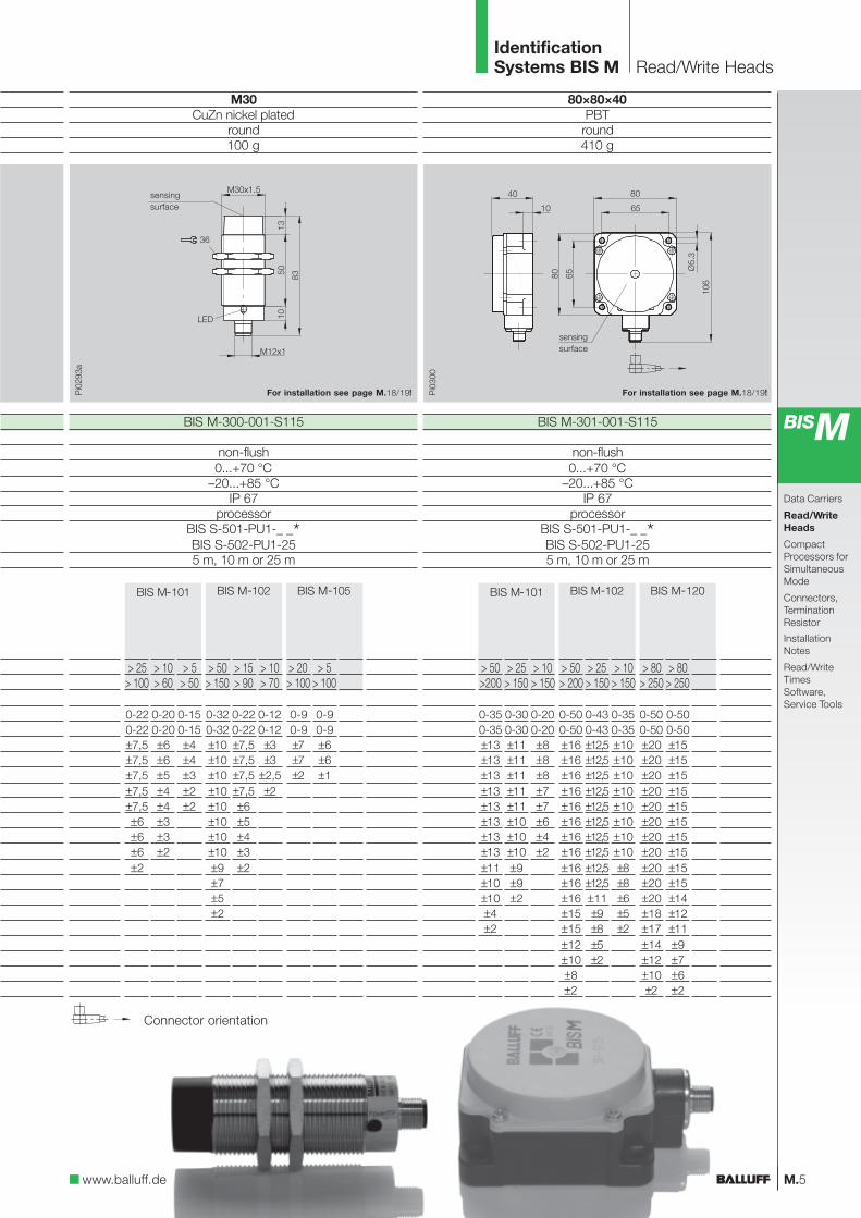
M30CuZn nickel plated
round100 g
BIS M-300-001-S115
non-flush0...+70 °C
–20...+85 °CIP 67
processorBIS S-501-PU1-_ _*BIS S-502-PU1-255 m, 10 m or 25 m
IdentificationSystems BIS M Read/Write Heads
M.5www.balluff.de
BISM
Data Carriers
Read/WriteHeads
CompactProcessors forSimultaneousMode
Connectors,TerminationResistor
InstallationNotes
Read/WriteTimesSoftware,Service Tools
80×80×40PBTround410 g
BIS M-301-001-S115
non-flush0...+70 °C
–20...+85 °CIP 67
processorBIS S-501-PU1-_ _*BIS S-502-PU1-255 m, 10 m or 25 m
Connector orientation
sensingsurface
For installation see page M.18/19!For installation see page M.18/19!
BIS M-101 BIS M-102 BIS M-105
> 50> 150
0-320-32±10±10±10±10±10±10±10±10±9±7±5±2
> 15> 90
0-220-22±7,5±7,5±7,5±7,5±6±5±4±3±2
> 10> 70
0-120-12±3±3
±2,5±2
> 25> 100
0-220-22±7,5±7,5±7,5±7,5±7,5±6±6±6±2
> 10> 60
0-200-20±6±6±5±4±4±3±3±2
> 5> 50
0-150-15±4±4±3±2±2
> 20> 100
0-90-9±7±7±2
> 5> 100
0-90-9±6±6±1
BIS M-101 BIS M-102 BIS M-120
> 50> 200
0-500-50±16±16±16±16±16±16±16±16±16±16±16±15±15±12±10±8±2
> 25> 150
0-430-43±12,5±12,5±12,5±12,5±12,5±12,5±12,5±12,5±12,5±12,5±11±9±8±5±2
> 10> 150
0-350-35±10±10±10±10±10±10±10±10±8±8±6±5±2
> 80> 250
0-500-50±20±20±20±20±20±20±20±20±20±20±20±18±17±14±12±10±2
> 80> 250
0-500-50±15±15±15±15±15±15±15±15±15±15±14±12±11±9±7±6±2
> 50>200
0-350-35±13±13±13±13±13±13±13±13±11±10±10±4±2
> 25> 150
0-300-30±11±11±11±11±11±10±10±10±9±9±2
> 10> 150
0-200-20±8±8±8±7±7±6±4±2
sensingsurface

DescriptionFunctionHousing material
Supply voltageRippleCurrent drawOperating temperatureStorage temperatureProtection per IEC 60529Read/Write Head portsService interface RS232Connection type
Connection forDescription Interface/Software:INTERBUS Remote bus stationINTERBUS Remote bus station with 2M BaudINTERBUS Installation busINTERBUS Installation bus with 2MBaud
Accessories (please order separately)
IdentificationSystems BIS M
Compact Processors6T-Simultaneous Operation
M.6
The compact classBIS M-6001 with itsreduced dimensions andvarious interface options canbe used wherever ambientconditions do not requirehigher protection. If IP 65 issufficient and no mediaaggressive to PS plastic arepresent, this device family isthe ideal solution.Small, compact, flexible andeconomical: these are thecharacteristics of this series.
Cost-effectiveidentification – operate2 Read/Write Headssimultaneously
– Data width on the bus,16 bytes
– Service friendly, allparameter data are storedin an exchangeablememory
– Accepts all read/writeheads
– Interface-compatible withBIS C, BIS L and BIS Sidentification systems

BIS M-6001-_ _ _-050-03-KL2read/write
ABS
BIS M-6021-_ _ _-050-03-ST8read/write
AlSi 12
IdentificationSystems BIS M
Compact Processors6T-Simultaneous Operation
M.7
Threaded coverBKS 23-CS-00for M23 plug connectionIP 65 protective cover forunused connectors!
www.balluff.de
BISM
The ruggedized versionBIS M-6021 is in spite of themechanically rugged die-cast aluminum housing asmall, flexible processorwhich is available withvarious interface options.
This version is ideal whereincreased demands onmechanical stability orchemical resistance aremade.
INTERBUS
BKS-S 84-00
BKS-S 79-00
BKS-S 83-00
Data Carriers
Read/WriteHeads
CompactProcessorsforSimultaneousMode
Connectors,TerminationResistor
InstallationNotes
Read/WriteTimesSoftware,Service Tools
24 V DC ±20 %≤ 10 %
≤ 400 mA0...+60 °C0...+60 °C
IP 65/NEMA 122 external
yesterminals 1 × Pg 9terminals 2 × Pg 11
2 read/write heads BIS M-3_ _
BIS M-6001-023-050-03-KL2
2 connector round 9-pin2 connector round 5-pin
2 read/write heads BIS M-3_ _
BIS M-6021-023-050-03-ST9BIS M-6021-023-050-03-ST9MBIS M-6021-023-050-03-ST8BIS M-6021-023-050-03-ST8M
BKS 23-CS-00connector page M.15

DescriptionFunctionHousing material
Supply voltageRippleCurrent drawOperating temperatureStorage temperatureProtection per IEC 60529Read/Write Head portsService interface RS232Connection type
Connection forDescription Interface/Software:PROFIBUS-DPAccessories includedAccessories (please order separately)
IdentificationSystems BIS M
Compact Processors6T-Simultaneous Operation
M.8
The compact classBIS M-6002 with itsreduced dimensions andvarious interface options canbe used wherever ambientconditions do not requirehigher protection. If IP 65 issufficient and no mediaaggressive to PS plastic arepresent, this device family isthe ideal solution.Small, compact, flexible andeconomical: these are thecharacteristics of this series.
Cost-effectiveidentification – operate2 Read/Write Headssimultaneously
– Selectable division ofthe data width on thePROFIBUS-DP,4 to 128 bytes
– Free assigning of the datawidth for each read/writehead
– Optimum data speed,internal cycle time isshorter than the BUSactivation time
– Service friendly, allparameter data are storedin an exchangeablememory
– BUS address selectablewith switches
– Accepts all read/writeheads
– Interface-compatible withBIS C, BIS L and BIS Sidentification systems

BIS M-6002-019-050-03-ST11read/write
ABS
BIS M-6022-019-050-03-ST14read/write
AlSi 12
IdentificationSystems BIS M
Compact Processors6T-Simultaneous Operation
M.9
PROFIBUS-DP
Threaded coverBKS 12-CS-01coded for M12 BConnector type
24 V DC ±20 %≤ 10 %
≤ 400 mA0...+60 °C0...+60 °C
IP 65/NEMA 122 external
yes
www.balluff.de
BISM
Data Carriers
Read/WriteHeads
CompactProcessorsforSimultaneousMode
Connectors,TerminationResistor
InstallationNotes
Read/WriteTimesSoftware,Service Tools
BKS-S 105-00
BKS-S 79-00
BKS-S 103-00
The ruggedized versionBIS M-6022 is in spite of themechanically rugged die-cast aluminum housing asmall, flexible processorwhich is available withvarious interface options.
This version is ideal whereincreased demands onmechanical stability orchemical resistance aremade.
2 connector round 5-pin, B-coded1 connector round 5-pin
2 read/write heads BIS M-3_ _
BIS M-6002-019-050-03-ST11software GSD-fileBKS 12-CS-01
connector page M.15-17
2 connector round 5-pin, B-coded,2 connector round 5-pin
2 read/write heads BIS M-3_ _
BIS M-6022-019-050-03-ST14software GSD-fileBKS 12-CS-01
connector page M.15-17

DescriptionFunctionHousing material
Supply voltageRippleCurrent drawOperating temperatureStorage temperatureProtection per IEC 60529Read/Write Head portsService interface RS232Connection typeConnection forDescription Interface/Software:DeviceNetAccessories includedAccessories (please order separately)
IdentificationSystems BIS M
Compact Processors6T-Simultaneous Operation
M.10
The compact classBIS M-6003 with itsreduced dimensions andvarious interface options canbe used wherever ambientconditions do not requirehigher protection. If IP 65 issufficient and no mediaaggressive to PS plastic arepresent, this device family isthe ideal solution.Small, compact, flexible andeconomical: these are thecharacteristics of this series.
Cost-effectiveidentification – operate2 Read/Write Headssimultaneously
– Freely selectable buffersize between 0 and256 bytes
– Service friendly, allparameter data are storedin an exchangeablememory
– Accepts all read/writeheads
– Interface-compatible withBIS C, BIS L and BIS Sidentification systems

BKS-S 99-00
BKS-S 79-00
BKS-S 98-00
BKS-S 98-R01
BIS M-6003-_ _ _-650-03-ST12read/write
ABS
BIS M-6023-_ _ _-050-03-ST13read/write
AlSi 12
IdentificationSystems BIS M
Compact Processors6T-Simultaneous Operation
M.11www.balluff.de
BISM
DeviceNetTM
Data Carriers
Read/WriteHeads
CompactProcessorsforSimultaneousMode
Connectors,TerminationResistor
InstallationNotes
Read/WriteTimesSoftware,Service Tools
The ruggedized versionBIS M-6023 is in spite of themechanically rugged die-cast aluminum housing asmall, flexible processorwhich is available withvarious interface options.
This version is ideal whereincreased demands onmechanical stability orchemical resistance aremade.
3 connector round 5-pin2 read/write heads BIS M-3_ _
BIS M-6003-025-050-03-ST12software EDS-file
connector page M.15/18/19
4 connector round 5-pin2 read/write heads BIS M-3_ _
BIS M-6023-025-050-03-ST13software EDS-file
connector page M.15-17
24 V DC ±20 %≤ 10 %
≤ 400 mA0...+50 °C0...+50 °C
IP 65/NEMA 122 external
yes

Order codeVersion
Connector typeVersionrecommended cableConductor cross sectionProtection per IEC 60529ambient temperature rangeAccessories includedCable
BIS S-501-PU1-_ _for read/write head
M128-pin, female
8×0.25 mm²IP 67
BKS-S117-00one end molded-in,other end pigtailed
IdentificationSystems BIS M Connectors
M.12
ConnectorsRead/Write Head
BKS-S117-00for connectingread/write head
to processor
M128-pin, male
IP 67–40...+85 °C
BIS S-502-PU1-25for read/write head
with fixedcable length 25 m
M128-pin, female
8×0.25 mm²IP 67
BKS-S117-00one end molded-in,other end pigtailed
Cable can be trailed and may also be shortenedto the required length. For fixed routing theminimum bending radius is 16 mm at an ambienttemperature of –40...+85 °C. When cable is trailedthe min. bending radius is 80 mm at an ambienttemperature of –25...+85 °C.Please indicate cable length in ordering code!05 = Length 5 m10 = Length 10 m25 = Length 25 m

M.13
IdentificationSystems BIS M Connectors
www.balluff.de
BISM
Data Carriers
Read/WriteHeads
CompactProcessors forSimultaneousMode
Connectors,TerminationResistor
InstallationNotes
Read/WriteTimesSoftware,Service Tools
INTERBUSBKS-S 83-00
or connection toprocessors
BIS M-6021 output
round-connector9-pin, male
LiYCY-00.5 mm²
IP 67–40...+85 °C
BKS-S 84-00for connection to
processorsBIS M-6021 input
round-connector9-pin, female
LiYCY-00.5 mm²
IP 67–40...+85 °C
BKS-S 79-00for connection to
processorsBIS M-6_ _
round-connector5-pin, female
LiYCY-00.34 mm²
IP 67–40...+85 °C
BKS 23-CS-00IP 65 threaded cover for
unused terminals!
Supply voltagefor all BIS M-6_ _
BIS C-522-PVC-...connector M12 and
MIN D withfixed cable length 2 m
for RS232 connection to PC
Please indicate cablelength in ordering code!02 = Length 2 m03 = Length 3 m
IdentificationSystems BIS M Connectors
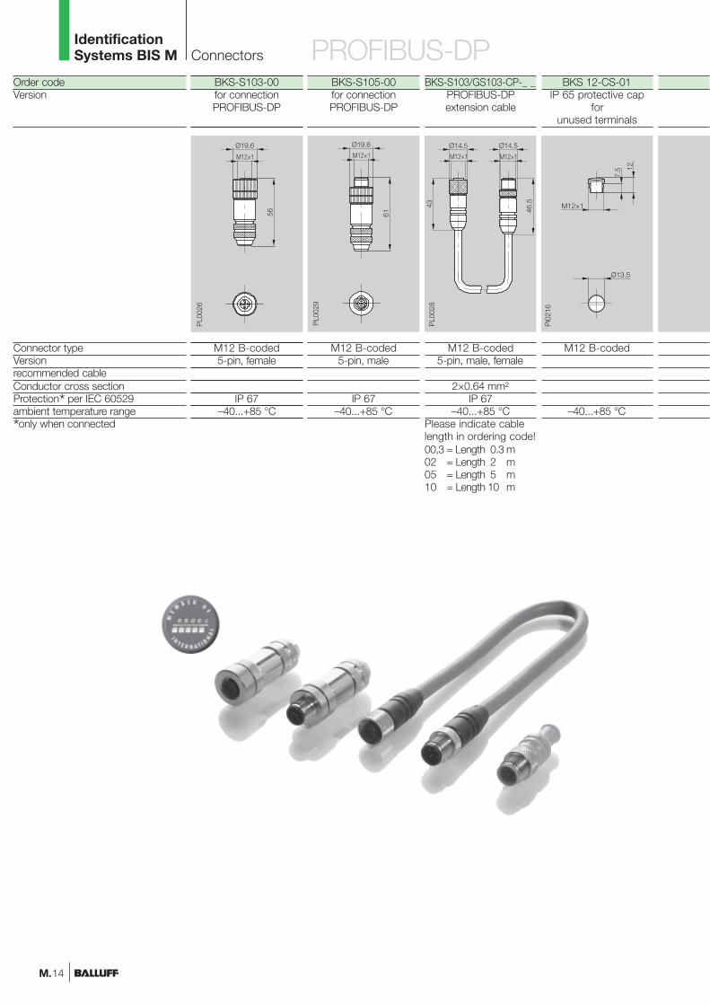
Order codeVersion
Connector typeVersionrecommended cableConductor cross sectionProtection* per IEC 60529ambient temperature range
*only when connected
M.14
BKS 12-CS-01IP 65 protective cap
forunused terminals
M12 B-coded
–40...+85 °C
BKS-S103/GS103-CP-_ _PROFIBUS-DPextension cable
M12 B-coded5-pin, male, female
2×0.64 mm²IP 67
–40...+85 °CPlease indicate cablelength in ordering code!00,3 = Length 0.3 m02 = Length 2 m05 = Length 5 m10 = Length 10 m
BKS-S105-00for connectionPROFIBUS-DP
M12 B-coded5-pin, male
IP 67–40...+85 °C
BKS-S103-00for connectionPROFIBUS-DP
M12 B-coded5-pin, female
IP 67–40...+85 °C
PROFIBUS-DP

BKS-S 98-00for connection to
processorsBIS L-6023 DeviceNet
round-connector5-pin, male
LiYCY-00.5 mm²
IP 67–40...+90 °C
BKS-S 99-00for connection to
processorsBIS L-6023 DeviceNet
round-connector5-pin, female
LiYCY-00.5 mm²
IP 67–40...+90 °C
IdentificationSystems BIS M
Connectors,Termination Resistor
M.15
BKS-S 98-R01termination resistor for
processorsBIS L-6023 DeviceNet
round-connector5-pin, male
IP 67–40...+85 °C
www.balluff.de
BISM
Data Carriers
Read/WriteHeads
CompactProcessors forSimultaneousMode
Connectors,TerminationResistor
InstallationNotes
Read/WriteTimesSoftware,Service Tools
BKS-S105-R01PROFIBUS-DP
termination resistor
M12 B-coded5-pin, male
IP 67–40...+85 °C
DeviceNetTM

BKS-S 95-00BIS M-6003-...
Rundsteckverbinder
ound-connector5-pin, right angle, male
6...8 mm
IP 67 (when attached)
BKS-S 92-00BIS M-6003-...
Rundsteckverbinder
round-connector5-pin, female
6...8 mm
IP 67 (when attached)
IdentificationSystems BIS M Connectors
Order codeVersion
Connector typeVersionCable diameterNo. of wires × conductor cross sectionProtection per IEC 60529Resistor
M.16
BKS-S 94-00BIS M-6003-...
Rundsteckverbinder
round-connector5-pin, male6...8 mm
IP 67 (when attached)
BKS-S 93-00BIS M-6003-...
Rundsteckverbinder9-polig, Buchse
round-connector5-pin, right angle, female
6...8 mm
IP 67 (when attached)
BKS-S 92-00/-S 93-00/ BKS-S 92-R01/-S 94-00/-S 95-00 -S 94-R01
121 Ohm
Pin assignments Pin Signal Pin Signal1 Drain 1 –2 V+ 2 –3 V– 3 –4 CAN_H 45 CAN_L 5
View offemale coupling side

IdentificationSystems BIS M
Connectors,Termination Resistor
M.17
BKS-S 92-R01BIS M-6003-...
termination resistor
round-connector5-pin, female
IP 68121 Ohm
BKS-S 94-R01BIS M-6003-...
termination resistor
round-connector5-pin, male
IP 68121 Ohm
BKS-S 92-16/GS92-_ _BIS M-6003-...
extension
round-connector5-pin, male, female
5×0.34 mm2
IP 67
Please indicate cablelength in ordering code!02 = Length 2 m05 = Length 5 m10 = Length 10 m
BKS-S 92-TA1BIS M-6003-...
round-connectorT-splitter, 2 × female, 1 × male
IP 65
www.balluff.de
BISM
Data Carriers
Read/WriteHeads
CompactProcessors forSimultaneousMode
Connectors,TerminationResistor
InstallationNotes
Read/WriteTimesSoftware,Service Tools
DeviceNetTM

IdentificationSystems BIS M Installation Notes
M.18 www.balluff.de
BIS M-101-01/L> 100 mm> 200 mm> 100 mm
Minimum distancebetween two datacarriers
BIS M-102-01/L> 150 mm> 200 mm> 100 mm
BIS M-105-01/A> 100 mm
> 100 mm
BIS M-120-01/L
> 250 mm
BIS M-300BIS M-301BIS M-302
200 mm600 mm100 mm
Minimum distancebetween two read/write heads
Mounting the read/write heads on metalframes
If the read/write heads are mounted so that they arejoined through an enclosed metal frame, mutualinterference may result (conductor loop).This may reduce the read/write distances. The smallerthe read/write head, the less the interference.This may result in a reduction of the maximum distanceby 80 %. In such a case you should test the actualeffective read distance.
read/write head Metal frame
BIS M-300BIS M-301BIS M-302
Order code
Shock loadVibration
Data carriers and read/write heads
Order code
Shock loadVibration
Processors
BIS M-1_ _, BIS M-3_ _
100 g/6 ms per EN 60068-2-27 and 100 g/2 ms per EN 60068-2-2920 g, 10...2000 Hz per EN 60068-2-6
BIS M-6_ _ _
15 g/11 ms per EN 60068-2-27 and 15 g/6 ms per EN 60068-2-295 g, 10...150 Hz per EN 60068-2-6
MechanicalStrength
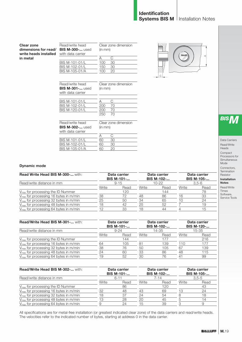
Read Write Head BIS M-300-... with:
Read/write distance in mm
Vmax for processing the ID NummerVmax for processing 16 bytes in m/minVmax for processing 32 bytes in m/minVmax for processing 48 bytes in m/minVmax for processing 64 bytes in m/min
Read/write headBIS M-300-... usedwith data carrier
BIS M-101-01/LBIS M-102-01/LBIS M-105-01/A
Clear zone dimension(in mm)
A C100 30150 30100 20
M.19
IdentificationSystems BIS M Installation Notes
Clear zonedimensions for read/write heads installedin metal
BISM
Data Carriers
Read/WriteHeads
CompactProcessors forSimultaneousMode
Connectors,TerminationResistor
InstallationNotes
Read/WriteTimesSoftware,Service Tools
Read/write headBIS M-301-... usedwith data carrier
BIS M-101-01/LBIS M-102-01/LBIS M-120-01/L
Clear zone dimension(in mm)
A C200 70200 70250 70
Read/write headBIS M-302-... usedwith data carrier
BIS M-101-01/LBIS M-102-01/LBIS M-105-01/A
Clear zone dimension(in mm)
A C60 3060 3060 20
Dynamic mode
Data carrierBIS M-101-...
9-15Write Read
12038 7225 5018 4212 33
Data carrierBIS M-102-...
10-22Write Read
14448 8634 6525 5218 44
Data carrierBIS M-105-...
3,5-6Write Read
7816 3310 247 194 15
Read/Write Head BIS M-301-... with:
Read/write distance in mm
Vmax for processing the ID NummerVmax for processing 16 bytes in m/minVmax for processing 32 bytes in m/minVmax for processing 48 bytes in m/minVmax for processing 64 bytes in m/min
Data carrierBIS M-101-...
9-24Write Read
14464 10538 7624 6019 52
Data carrierBIS M-102-...
14-35Write Read
17781 13950 10533 8630 76
Data carrierBIS M-120-...
15-35Write Read
216110 17767 13948 11541 99
Read/Write Head BIS M-302-... with:
Read/write distance in mm
Vmax for processing the ID NummerVmax for processing 16 bytes in m/minVmax for processing 32 bytes in m/minVmax for processing 48 bytes in m/minVmax for processing 64 bytes in m/min
Data carrierBIS M-101-...
6-11Write Read
8632 4818 3713 289 24
Data carrierBIS M-102-...
7-14Write Read
12043 6924 5420 4515 39
Data carrierBIS M-105-...
3,5-5Write Read
4313 248 185 143 9
All specifications are for metal-free installation (or greatest indicated clear zone) of the data carriers and read/write heads.The velocities refer to the indicated number of bytes, starting at address 0 in the data carrier.

IdentificationSystems BIS M Read/Write Times
M.20
Memory access
Data carrierrecognition
Our processors can read or write each individual byte in the data carrier.But since the data carrier is divided into 16-byte blocks, the actualreading and writing is done by blocks. Our processor electronicsconverts this time accordingly. To calculate the read/write times the blockread or write time must however be used.
20 ms are required to recognize a data carrier.
Read TimesBIS M-1_ _
Read and write 183 bytes starting at address 42
Address 42 is in Block 3 (42/16)Address 224 is in Block 14 (224/16)
Therefore a total of 12 blocks will be processed, where the first blockalways has a slightly longer read or write time.
Read time = 20 ms + 11* 10 ms = 130 msWrite time = 40 ms + 11* 30 ms = 370 ms
Note! Fluctuations in the ms range are possible.Electrical noise effects may increase the read/write time.
Write TimesBIS M-1_ _
Example
Data carrier with 16 byte blocksByte write time [ms] von0 to 16 40for each additional16 bytes started addan additional 30
Data carrier with 16 byte blocksByte read time [ms]from 0 to 16 20for each additional16 bytes started addan additional 10

M.21
IdentificationSystems BIS M Software and Service Tools
www.balluff.de
BISM
Data Carriers
Read/WriteHeads
CompactProcessors forSimultaneousMode
Connectors,TerminationResistor
InstallationNotes
Read/WriteTimesSoftware,Service Tools
PC
Processor
Read/write head
Read/writedata transfer
Data carrier
BISEDIT
makes use of the mask filecreated in BISKMASK andoutputs the data carrier datawith the assigned fixed textsto the monitor screen ora printer. There is also theoption of storing the datacarrier data on diskette orhard disk, or downloading itfrom those sources.
It is also possible to modifythe data carrier data.
A password can be assignedto prevent data from beingchanged.
BISMASK
enables the user to assigncertain fixed texts to thevarious data on the datacarrier.
At the same time, the usercan define how the datais represented and createsystem settings for later usewith BISEDIT.
This organization is storedin a mask which is used byBISEDIT.
BISMASK/BISEDIT
The BISMASK/BISEDITsoftware package makes itpossible to create a manualwork station for the BalluffIdentification System using astandard PC.
Requirements:PC with a serial port,Windows 95, Windows 98or Windows NT, floppy drive,hard drive.
The workstation consists ofa PC, a BIS C processorwith Balluff Dialog-Protocol(-007), and a read/writehead.
The program packageconsists of two programsections:
Software CouplingBIS C-60_2 for SiemensSimatic S7
Function modules for linkinga Processor with INTERBUS
or PROFIBUS-DP option toa Simatic S7 controller.
The function modules offerthe full functionality of theBalluff Processors. Data areexchanged through the I/Osection of the controller.
Features:– short startup times– easy system operation– full command set
PROFIBUS-DPMaster Simulator
The PROFIBUS-DP MasterSimulator is a simple, univer-sal program for dataexchange with PROFIBUSslaves from virtually anymanufacturer over PROFI-BUS-DP.
Included with delivery are:
– SoftwarePROFIBUS-DP mastersimulator
– PROFIBUS-DP converter– D-Sub data cable

No.
840
841
E
. E
ditio
n 05
03;
Sub
ject
to
mod
ifica
tion.
... non-contact data communication at 13.56 MHzIdentification Systems BIS M
Go here forfast information!
Balluff GmbHSchurwaldstrasse 973765 Neuhausen a.d.F.GermanyPhone +49 (0) 71 58/1 73-0Fax +49 (0) 71 58/50 10E-Mail: [email protected]
For more Identification Systemsrefer to catalogs for BIS C, BIS Land BIS S, on CD-ROM or online!
![Bach Cantatas, Vol. 6 -M. Suzuki & Bach Collegium Japan ...BIS-CD851].pdf · Title: Bach Cantatas, Vol. 6 -M. Suzuki & Bach Collegium Japan (BIS CD) Created Date: 8/20/2009 9:32:49](https://static.documents.pub/doc/80x56/5e219b464a65a042f52e5cdd/bach-cantatas-vol-6-m-suzuki-bach-collegium-japan-bis-cd851pdf.jpg)


![Bach Cantatas, Vol. 4 -M. Suzuki & Bach Collegium Japan (BIS CD)BIS-CD801].pdf · 2020. 7. 30. · Title: Bach Cantatas, Vol. 4 -M. Suzuki & Bach Collegium Japan (BIS CD) Created](https://static.documents.pub/doc/80x56/60b03f99b59c9b019f4b95a2/bach-cantatas-vol-4-m-suzuki-bach-collegium-japan-bis-cd-bis-cd801pdf.jpg)


