Pressure transmitter SITRANS P, Z series (7MF1564) Operating Instructions (Compact)
Product information
Safety notes
This device left the factory in a perfect state with regard to safety. To maintain this status and to ensure safe operation of the device, observe the following notes:
CAUTION The device may only be used for the purposes specified in these instructions. ● Observe the test certification, provisions and laws applicable
in your country during connection, assembly and operation. ● "Intrinsically-safe" devices lose their certification as soon as
they are operated on circuits which do not correspond with the test certification valid in their country.
● The device can be operated both at high pressure and with aggressive and hazardous media. Therefore, improper use of this device may lead to serious injury and or considerable damage to property. Above all, it must be noted when the device was in use and is to be exchanged.
● For this reason, only qualified personnel may set up, install, commission, and operate the product.
Application SITRANS P, Z series (7MF1564)
The pressure transmitter is used for measuring the relative pressure and absolute pressure of gases and liquids in the following industrial areas: ● Mechanical engineering ● Marine ● Power engineering ● Chemicals ● Water supply ● Pharmaceuticals
Hardware configuration
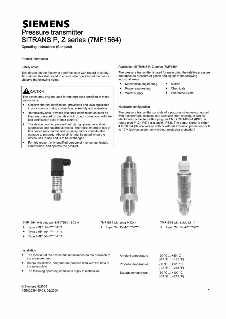
The pressure transmitter consists of a piezoresistive measuring cell with a diaphragm, installed in a stainless steel housing. It can be electrically connected with a plug per EN 175301-803-A (IP65), a round plug M12 (IP67) or a cable (IP68). The output signal is either 4 to 20 mA (device version with or without explosion protection) or 0 to 10 V (device version only without explosion protection)
7MF1564 with plug per EN 175301-803-A 7MF1564 with plug M12x1 7MF1564 with cable (2 m) ● Type 7MF1564-*****-1**1 ● Type 7MF1564-*****-3**1 ● Type 7MF1564-*****-4**1
● Type 7MF1564-*****-2**1 ● Type 7MF1564-*****-6**1
Installation ● The location of the device has no influence on the precision of
the measurement. ● Before installation, compare the process data with the data of
the rating plate. ● The following operating conditions apply to installation:
Ambient temperature -20 °C ... +85 °C (-13 °F ... +185 °F)
Process temperature -30 °C ... +120 °C (-22 °F ... +248 °F)
Storage temperature -50 °C ... +100 °C (-58 °F ... +212 °F)
SITRANS P, Z series (7MF1564) 2 A5E02059155-01, 02/2008
● The medium being measured must be suitable for the parts of the pressure transmitter in contact with the medium.
● The burst pressure must not be exceeded. ● Attach the devices with fixed cable installation.
Electrical connection
For the device version with plug per EN 175301-803-A and plug M12 x 1 (mating connector as option), we recommend the screened 2- or 3-wire cable (4.5 to 7 mm outside diameter).
The cable is grounded at only one point, e.g. in the switching cabinet.
The grounding connection is conductively bonded to the transmitter housing.
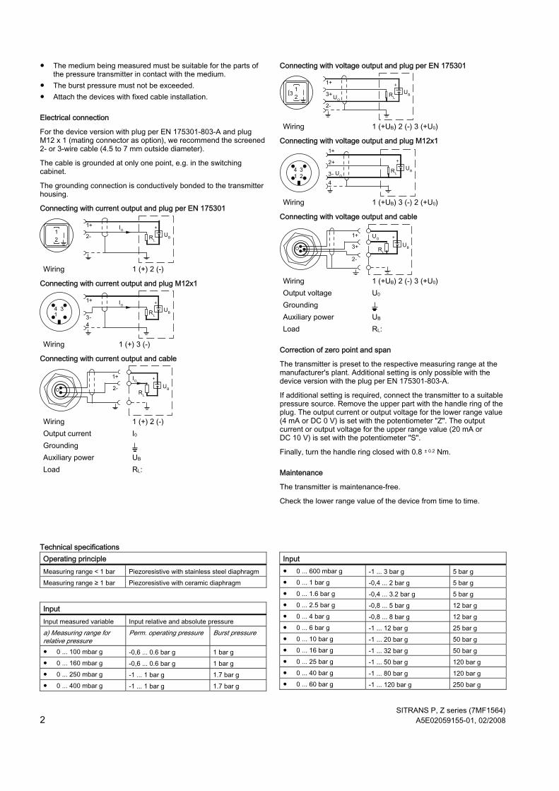
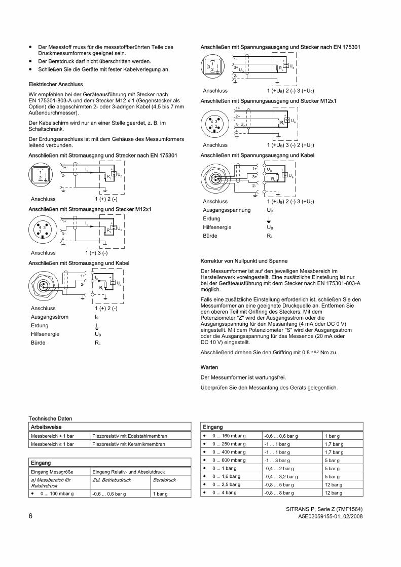
Connecting with current output and plug per EN 175301
Wiring 1 (+) 2 (-)
Connecting with current output and plug M12x1
Wiring 1 (+) 3 (-)
Connecting with current output and cable
Wiring 1 (+) 2 (-) Output current I0 Grounding Auxiliary power UB Load RL:
Connecting with voltage output and plug per EN 175301
Wiring 1 (+UB) 2 (-) 3 (+U0)
Connecting with voltage output and plug M12x1
Wiring 1 (+UB) 3 (-) 2 (+U0)
Connecting with voltage output and cable
Wiring 1 (+UB) 2 (-) 3 (+U0) Output voltage U0 Grounding Auxiliary power UB Load RL:
Correction of zero point and span
The transmitter is preset to the respective measuring range at the manufacturer's plant. Additional setting is only possible with the device version with the plug per EN 175301-803-A.
If additional setting is required, connect the transmitter to a suitable pressure source. Remove the upper part with the handle ring of the plug. The output current or output voltage for the lower range value (4 mA or DC 0 V) is set with the potentiometer "Z". The output current or output voltage for the upper range value (20 mA or DC 10 V) is set with the potentiometer "S".
Finally, turn the handle ring closed with 0.8 ± 0.2 Nm.
Maintenance
The transmitter is maintenance-free.
Check the lower range value of the device from time to time.
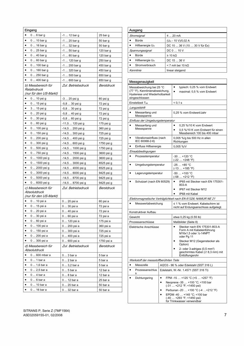
Technical specifications Operating principle Measuring range < 1 bar Piezoresistive with stainless steel diaphragm Measuring range ≥ 1 bar Piezoresistive with ceramic diaphragm
Input Input measured variable Input relative and absolute pressure a) Measuring range for relative pressure
Perm. operating pressure Burst pressure
● 0 ... 100 mbar g -0,6 ... 0.6 bar g 1 bar g ● 0 ... 160 mbar g -0,6 ... 0.6 bar g 1 bar g ● 0 ... 250 mbar g -1 ... 1 bar g 1.7 bar g ● 0 ... 400 mbar g -1 ... 1 bar g 1.7 bar g
Input ● 0 ... 600 mbar g -1 ... 3 bar g 5 bar g ● 0 ... 1 bar g -0,4 ... 2 bar g 5 bar g ● 0 ... 1.6 bar g -0,4 ... 3.2 bar g 5 bar g ● 0 ... 2.5 bar g -0,8 ... 5 bar g 12 bar g ● 0 ... 4 bar g -0,8 ... 8 bar g 12 bar g ● 0 ... 6 bar g -1 ... 12 bar g 25 bar g ● 0 ... 10 bar g -1 ... 20 bar g 50 bar g ● 0 ... 16 bar g -1 ... 32 bar g 50 bar g ● 0 ... 25 bar g -1 ... 50 bar g 120 bar g ● 0 ... 40 bar g -1 ... 80 bar g 120 bar g ● 0 ... 60 bar g -1 ... 120 bar g 250 bar g
SITRANS P, Z series (7MF1564) A5E02059155-01, 02/2008 3
Input ● 0 ... 100 bar g -1 ... 200 bar g 450 bar g ● 0 ... 160 bar g -1 ... 320 bar g 450 bar g ● 0 ... 250 bar g -1 ... 500 bar g 650 bar g ● 0 ... 400 bar g -1 ... 600 bar g 650 bar g b) Measuring ranges for relative pressure (only for US market)
Perm. operating pressure
Burst pressure
● 0 ... 10 psi g -3 ... 20 psi g 60 psi g ● 0 ... 15 psi g -5,8 ... 30 psi g 72 psi g ● 3 ... 15 psi g -5,8 ... 30 psi g 72 psi g ● 0 ... 20 psi g -5,8 ... 40 psi g 72 psi g ● 0 ... 30 psi g -5,8 ... 60 psi g 72 psi g ● 0 ... 60 psi g -11,5 ... 120 psi g 175 psi g ● 0 ... 100 psi g -14,5 ... 200 psi g 360 psi g ● 0 ... 150 psi g -14,5 ... 300 psi g 725 psi g ● 0 ... 200 psi g -14,5 ... 400 psi g 725 psi g ● 0 ... 300 psi g -14,5 ... 600 psi g 1750 psi g ● 0 ... 500 psi g -14,5 ... 1000 psi g 1750 psi g ● 0 ... 750 psi g -14,5 ... 1500 psi g 3600 psi g ● 0 ... 1000 psi g -14,5 ... 2000 psi g 3600 psi g ● 0 ... 1500 psi g -14,5 ... 3000 psi g 6525 psi g ● 0 ... 2000 psi g -14,5 ... 4000 psi g 6525 psi g ● 0 ... 3000 psi g -14,5 ... 6000 psi g 9425 psi g ● 0 ... 5000 psi g -14,5 ... 8700 psi g 9425 psi g ● 0 ... 6000 psi g -14,5 ... 8700 psi g 9425 psi g
c) Measuring ranges for absolute pressure (only for US market)
Perm. operating pressure
Burst pressure
● 0 ... 10 psi a 0 ... 20 psi a 60 psi a ● 0 ... 15 psi a 0 ... 30 psi a 72 psi a ● 0 ... 20 psi a 0 ... 40 psi a 72 psi a ● 0 ... 30 psi a 0 ... 60 psi a 72 psi a ● 0 ... 60 psi a 0 ... 120 psi a 175 psi a ● 0 ... 100 psi a 0 ... 200 psi a 360 psi a ● 0 ... 150 psi a 0 ... 300 psi a 725 psi a ● 0 ... 200 psi a 0 ... 400 psi a 725 psi a ● 0 ... 300 psi a 0 ... 600 psi a 1750 psi a
d) Measuring range for absolute pressure
Perm. operating pressure
Burst pressure
● 0 ... 600 mbar a 0 ... 3 bar a 5 bar a ● 0 ... 1 bar a 0 ... 2 bar a 5 bar a ● 0 ... 1.6 bar a 0 ... 3.2 bar a 5 bar a ● 0 ... 2.5 bar a 0 ... 5 bar a 12 bar a ● 0 ... 4 bar a 0 ... 8 bar a 12 bar a ● 0 ... 6 bar a 0 ... 12 bar a 25 bar a ● 0 ... 10 bar a 0 ... 20 bar a 50 bar a ● 0 ... 16 bar a 0 ... 32 bar a 50 bar a
Output Current signal 4 ... 20 mA ● Load (UH - 10 V)/0.02 A ● Auxiliary power UH DC 10 ... 36 V (10 … 30 V for Ex)
Output Voltage signal DC 0 … 10 V ● Load ≥ 10 kΩ ● Auxiliary power UH DC 15 ... 36 V ● Power consumption < 7 mA at 10 kΩ Characteristic Linear rising
Measuring accuracy Error in measurement at 25 °C (77 °F), including conformity error, hysteresis and repeatability
● Typical: 0.25 % of full scale value ● Maximum: 0,5 % of full scale value
Setting time T99 < 0.1 s Long-term drift ● Lower range value and
measuring span 0.25 % of full scale value/year
Ambient temperature influence ● Lower range value and
measuring span ● 0.25 %/10 K of full scale value ● 0.5 %/10 K of full scale value for a
measuring range of 100 to 400 mbar
● Influence of vibration (per IEC 60068-2-6)
0.005 %/g to 500 Hz in all directions
● Power supply influence 0.005 %/V Operating conditions ● Process temperature -30 to +120 °C
(-22 to +248 °F) ● Ambient temperature -25 to +85 °C
(-13 to +185 °F) ● Storage temperature -50 to +100 °C
(-58 to +212 °F) ● Degree of protection (as
per EN 60529) ● IP65 with plug per EN 175301-803-
A ● IP67 with plug M12 ● IP68 with cable
Electromagnetic compatibility per EN 61326; NAMUR NE 21 ● Measurement error ≤ 1 % of full scale value. Cable screen is
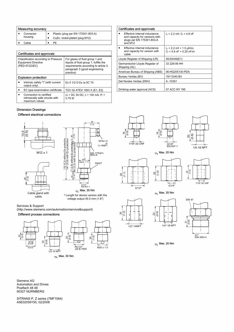
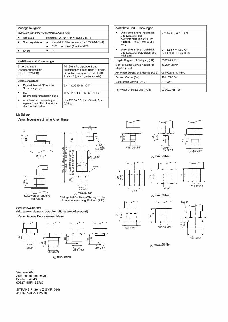
not connected to ground connection. Design Weight Approx. 0,25 kg (0.55 lb) Process connections Dimension Drawings (Page 4) Electrical connections ● Plug per EN 175301-803-A form A
with cable inletM16x1.5 or ½-14NPT or Pg 11
● Plug M12 (mating connector as option)
● 2- or 3-wire (0.5 mm2) screened lead (∅ 8.3 mm) with vent pipe
Material of the wetted parts ● Measuring cell AI2O3 - 96 % or stainless steel (SST 316 L) ● Process
Druckmessumformer SITRANS P, Serie Z (7MF1564) Betriebsanleitung (kompakt)
Produktinformation
Sicherheitshinweise
Dieses Gerät hat das Werk in sicherheitstechnisch einwandfreiem Zustand verlassen. Um diesen Zustand zu erhalten und um einen gefahrlosen Betrieb des Geräts sicherzustellen, beachten Sie folgende Hinweise:
VORSICHT Das Gerät darf nur zu den in dieser Anleitung vorgegebenen Zwecken eingesetzt werden. ● Bei Anschluss, Montage und Betrieb sind die für Ihr Land
gültigen Prüfbescheinigungen, Bestimmungen und Gesetze zu beachten.
● Geräte der Zündschutzart "Eigensicherheit" verlieren Ihre Zulassung, sobald sie an Stromkreisen betrieben wurden, die nicht der in Ihrem Land gültigen Prüfbescheinigung entsprechen.
● Das Gerät kann mit hohem Druck sowie aggressiven und gefährlichen Medien betrieben werden. Deshalb sind bei unsachgemäßem Umgang mit diesem Gerät schwere Körperverletzungen und/oder erheblicher Sachschaden nicht auszuschließen. Dies ist vor allem zu beachten, wenn das Gerät im Einsatz war und ausgetauscht wird.
● Deswegen dürfen die Aufstellung, Montage, Inbetriebsetzung und Betrieb des Produkts nur von qualifiziertem Personal vorgenommen werden.
Anwendungsbereich SITRANS P, Serie Z Typ 7MF1564
Der Druckmessumformer wird zur Messung von Relativdruck und Absolutdruck der Gase und der Flüssigkeiten in folgenden Industriebereichen eingesetzt: ● Maschinenbau ● Schiffsbau ● Energietechnik ● Chemie ● Wasserversorgung ● Pharmazie
Geräteaufbau
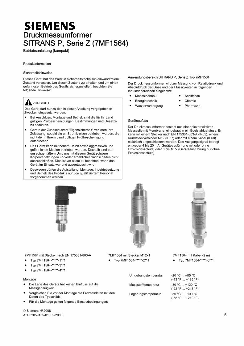
Der Druckmessumformer besteht aus einer piezoresistiven Messzelle mit Membrane, eingebaut in ein Edelstahlgehäuse. Er kann mit einem Stecker nach EN 175301-803-A (IP65), einem Rundsteckverbinder M12 (IP67) oder mit einem Kabel (IP68) elektrisch angeschlossen werden. Das Ausgangssignal beträgt entweder 4 bis 20 mA (Geräteausführung mit oder ohne Explosionsschutz) oder 0 bis 10 V (Geräteausführung nur ohne Explosionsschutz).
7MF1564 mit Stecker nach EN 175301-803-A 7MF1564 mit Stecker M12x1 7MF1564 mit Kabel (2 m) ● Typ 7MF1564-*****-1**1 ● Typ 7MF1564-*****-3**1 ● Typ 7MF1564-*****-4**1
● Typ 7MF1564-*****-2**1 ● Typ 7MF1564-*****-6**1
Montage ● Die Lage des Geräts hat keinen Einfluss auf die
Messgenauigkeit. ● Vergleichen Sie vor der Montage die Prozessdaten mit den
Daten des Typschilds. ● Für die Montage gelten folgende Einsatzbedingungen:
Umgebungstemperatur -20 °C ... +85 °C (-13 °F ... +185 °F)
Messstofftemperatur -30 °C ... +120 °C (-22 °F ... +248 °F)
Lagerungstemperatur -50 °C ... +100 °C (-58 °F ... +212 °F)
SITRANS P, Serie Z (7MF1564) 6 A5E02059155-01, 02/2008
● Der Messstoff muss für die messstoffberührten Teile des Druckmessumformers geeignet sein.
● Der Berstdruck darf nicht überschritten werden. ● Schließen Sie die Geräte mit fester Kabelverlegung an.
Elektrischer Anschluss
Wir empfehlen bei der Geräteausführung mit Stecker nach EN 175301-803-A und dem Stecker M12 x 1 (Gegenstecker als Option) die abgeschirmten 2- oder 3-adrigen Kabel (4,5 bis 7 mm Außendurchmesser).
Der Kabelschirm wird nur an einer Stelle geerdet, z. B. im Schaltschrank.
Der Erdungsanschluss ist mit dem Gehäuse des Messumformers leitend verbunden.
Anschließen mit Stromausgang und Strecker nach EN 175301
Der Messumformer ist auf den jeweiligen Messbereich im Herstellerwerk voreingestellt. Eine zusätzliche Einstellung ist nur bei der Geräteausführung mit dem Stecker nach EN 175301-803-A möglich.
Falls eine zusätzliche Einstellung erforderlich ist, schließen Sie den Messumformer an eine geeignete Druckquelle an. Entfernen Sie den oberen Teil mit Griffring des Steckers. Mit dem Potenziometer "Z" wird der Ausgangsstrom oder die Ausgangsspannung für den Messanfang (4 mA oder DC 0 V) eingestellt. Mit dem Potenziometer "S" wird der Ausgangsstrom oder die Ausgangsspannung für das Messende (20 mA oder DC 10 V) eingestellt.
Abschließend drehen Sie den Griffring mit 0,8 ± 0,2 Nm zu.
Warten
Der Messumformer ist wartungsfrei.
Überprüfen Sie den Messanfang des Geräts gelegentlich.
Technische Daten Arbeitsweise Messbereich < 1 bar Piezoresistiv mit Edelstahlmembran Messbereich ≥ 1 bar Piezoresistiv mit Keramikmembran
Eingang Eingang Messgröße Eingang Relativ- und Absolutdruck a) Messbereich für Relativdruck
Zul. Betriebsdruck Berstdruck
● 0 ... 100 mbar g -0,6 ... 0,6 bar g 1 bar g
Eingang ● 0 ... 160 mbar g -0,6 ... 0,6 bar g 1 bar g ● 0 ... 250 mbar g -1 ... 1 bar g 1,7 bar g ● 0 ... 400 mbar g -1 ... 1 bar g 1,7 bar g ● 0 ... 600 mbar g -1 ... 3 bar g 5 bar g ● 0 ... 1 bar g -0,4 ... 2 bar g 5 bar g ● 0 ... 1,6 bar g -0,4 ... 3,2 bar g 5 bar g ● 0 ... 2,5 bar g -0,8 ... 5 bar g 12 bar g ● 0 ... 4 bar g -0,8 ... 8 bar g 12 bar g
SITRANS P, Serie Z (7MF1564) A5E02059155-01, 02/2008 7
Eingang ● 0 ... 6 bar g -1 ... 12 bar g 25 bar g
● 0 ... 10 bar g -1 ... 20 bar g 50 bar g ● 0 ... 16 bar g -1 ... 32 bar g 50 bar g ● 0 ... 25 bar g -1 ... 50 bar g 120 bar g ● 0 ... 40 bar g -1 ... 80 bar g 120 bar g ● 0 ... 60 bar g -1 ... 120 bar g 250 bar g ● 0 ... 100 bar g -1 ... 200 bar g 450 bar g ● 0 ... 160 bar g -1 ... 320 bar g 450 bar g ● 0 ... 250 bar g -1 ... 500 bar g 650 bar g ● 0 ... 400 bar g -1 ... 600 bar g 650 bar g
b) Messbereich für Relativdruck (nur für den US-Markt)
Zul. Betriebsdruck Berstdruck
● 0 ... 10 psi g -3 ... 20 psi g 60 psi g ● 0 ... 15 psi g -5,8 ... 30 psi g 72 psi g ● 3 ... 15 psi g -5,8 ... 30 psi g 72 psi g ● 0 ... 20 psi g -5,8 ... 40 psi g 72 psi g ● 0 ... 30 psi g -5,8 ... 60 psi g 72 psi g ● 0 ... 60 psi g -11,5 ... 120 psi g 175 psi g ● 0 ... 100 psi g -14,5 ... 200 psi g 360 psi g ● 0 ... 150 psi g -14,5 ... 300 psi g 725 psi g ● 0 ... 200 psi g -14,5 ... 400 psi g 725 psi g ● 0 ... 300 psi g -14,5 ... 600 psi g 1750 psi g ● 0 ... 500 psi g -14,5 ... 1000 psi g 1750 psi g ● 0 ... 750 psi g -14,5 ... 1500 psi g 3600 psi g ● 0 ... 1000 psi g -14,5 ... 2000 psi g 3600 psi g ● 0 ... 1500 psi g -14,5 ... 3000 psi g 6525 psi g ● 0 ... 2000 psi g -14,5 ... 4000 psi g 6525 psi g ● 0 ... 3000 psi g -14,5 ... 6000 psi g 9425 psi g ● 0 ... 5000 psi g -14,5 ... 8700 psi g 9425 psi g ● 0 ... 6000 psi g -14,5 ... 8700 psi g 9425 psi g
c) Messbereich für Absolutdruck (nur für den US-Markt)
Zul. Betriebsdruck Berstdruck
● 0 ... 10 psi a 0 ... 20 psi a 60 psi a ● 0 ... 15 psi a 0 ... 30 psi a 72 psi a ● 0 ... 20 psi a 0 ... 40 psi a 72 psi a ● 0 ... 30 psi a 0 ... 60 psi a 72 psi a ● 0 ... 60 psi a 0 ... 120 psi a 175 psi a ● 0 ... 100 psi a 0 ... 200 psi a 360 psi a ● 0 ... 150 psi a 0 ... 300 psi a 725 psi a ● 0 ... 200 psi a 0 ... 400 psi a 725 psi a ● 0 ... 300 psi a 0 ... 600 psi a 1750 psi a
d) Messbereich für Absolutdruck
Zul. Betriebsdruck Berstdruck
● 0 ... 600 mbar a 0 ... 3 bar a 5 bar a ● 0 ... 1 bar a 0 ... 2 bar a 5 bar a ● 0 ... 1,6 bar a 0 ... 3,2 bar a 5 bar a ● 0 ... 2,5 bar a 0 ... 5 bar a 12 bar a ● 0 ... 4 bar a 0 ... 8 bar a 12 bar a ● 0 ... 6 bar a 0 ... 12 bar a 25 bar a ● 0 ... 10 bar a 0 ... 20 bar a 50 bar a ● 0 ... 16 bar a 0 ... 32 bar a 50 bar a
Ausgang Stromsignal 4 ... 20 mA ● Bürde (UH - 10 V)/0,02 A ● Hilfsenergie UH DC 10 ... 36 V (10 … 30 V für Ex) Spannungssignal DC 0 … 10 V ● Bürde ≥ 10 kΩ ● Hilfsenergie UH DC 15 ... 36 V ● Stromverbrauch < 7 mA bei 10 kΩ Kennlinie linear steigend
Messgenauigkeit Messabweichung bei 25 °C (77 °F), Kennlinienabweichung, Hysterese und Wiederholbarkeit eingeschlossen
● typisch: 0,25 % vom Endwert ● maximal: 0,5 % vom Endwert
Einstellzeit T99 < 0,1 s Langzeitdrift ● Messanfang und
Messspanne 0,25 % vom Endwert/Jahr
Einfluss der Umgebungstemperatur ● Messanfang und
Messspanne ● 0,25 %/10 K vom Endwert ● 0,5 %/10 K vom Endwert für einen
Messbereich 100 bis 400 mbar ● Vibrationseinfluss (nach
IEC 60068-2-6) 0,005 %/g bis 500 Hz in allen Richtungen
(-22 … +248 °F) ● Umgebungstemperatur -25 … +85 °C
(-13 … +185 °F) ● Lagerungstemperatur -50 … +100 °C
(-58 … +212 °F) ● Schutzart (nach EN 60529) ● IP65 mit Stecker nach EN 175301-
803-A ● IP67 mit Stecker M12 ● IP68 mit Kabel
Elektromagnetische Verträglichkeit nach EN 61326; NAMUR NE 21 ● Messwertabweichung ≤ 1 % vom Endwert. Kabelschirm ist
nicht auf Erdungsanschluss aufgelegt. Konstruktiver Aufbau Gewicht etwa 0,25 kg (0.55 lb) Prozessanschlüsse Maßbilder (Seite 8) Elektrische Anschlüsse ● Stecker nach EN 175301-803-A
Form A mit Kabeleinführung M16x1,5 oder ½-14NPT oder Pg 11
● Stecker M12 (Gegenstecker als Option)
● 2- oder 3-adriges (0,5 mm2) geschirmtes Kabel (∅ 8,3 mm) mit Entlüftungsrohr
Werkstoff der messstoffberührten Teile ● Messzelle AI2O3 - 96 % oder Edelstahl (SST 316 L) ● Prozessanschlus
s Edelstahl, W.-Nr. 1.4571 (SST 316 Ti)
● Dichtungsring ● FPM -15 … +125 °C (+5 … +257 °F) ● Neoprene -35 … +100 °C; <100 bar