ESPOO 2002 VTT RESEARCH NOTES 2158 Masanori Shukuya & Abdelaziz Hammache Introduction to the Concept of Exergy - for a Better Understanding of Low-Temperature-Heating and High-Temperature- Cooling Systems
Transcript
VTT RESEA
RCH N
OTES 2158Introduction to the Concept of Exergy
Tätä julkaisua myy Denna publikation säljs av This publication is available from
ISBN 951–38–6074–4 (soft back ed.) ISBN 951–38–6075–2 (URL: http://www.inf.vtt.fi/pdf/)ISSN 1235–0605 (soft back ed.) ISSN 1455–0865 (URL: http://www.inf.vtt.fi/pdf/)
ESPOO 2002 VTT RESEARCH NOTES 2158
Masanori Shukuya & Abdelaziz Hammache
Introduction to the Concept of Exergy -for a Better Understanding of Low-Temperature-Heatingand High-Temperature-Cooling Systems
Submitted to IEA ANNEX37“Low Exergy Systems for Heating and Cooling of Buildings”
VTT TIEDOTTEITA – RESEARCH NOTES
VTT RAKENNUS- JA YHDYSKUNTATEKNIIKKA – VTT BYGG OCHTRANSPORT – VTT BUILDING AND TRANSPORT
2116 Ryynänen, Tiia, Kallonen, Raija & Ahonen, Eino. Palosuojatut tekstiilit. Ominaisuudetja käyttö. 2001. 101 s.
2118 Kärki, Otto. Alkolukko rattijuopumuksen ehkäisyssä. Esiselvitys. 2001. 85 s. + liitt. 3 s.
2119 Tillander, Kati & Keski-Rahkonen, Olavi. Rakennusten syttymistaajuudet PRONTO-tietokannasta 1996–1999. 2001. 66 s. + liitt. 16 s.
2120 Koota, Jaana. Construction site safety. Case United States. 2001. 39 p. + app. 3 p.
2121 Tervonen, Juha & Räsänen, Jukka. Environmental assessment of strategic transport ac-tions. SEA in CODE-TEN. 2001. 25 p. + app. 7 p.
2123 Hietaniemi, Jukka, Baroudi, Djebar, Korhonen, Timo, Björkman, Jouni, Kokkala, Matti& Lappi, Esa. Yksikerroksisen teollisuushallin rakenteiden palonkestävyyden vaikutuspaloturvallisuuteen. Riskianalyysi ajasta riippuvaa tapahtumapuumallia käyttäen. 2002.95 s. + liitt. 51 s.
2124 Talja, Asko, Toratti, Tomi & Järvinen, Erkki. Lattioiden värähtelyt. Suunnittelu ja ko-keellinen arviointi. 2002. 51 s. + liitt. 13 s.
2125 Riihimäki, Markku & Siekkinen, Heidi. Asiakastarpeet kiinteistöliiketoiminnassa. Liike-ja toimistokiinteistöt. 2002. 74 s. + liitt. 10 s.
2126 Kauppinen, Anna-Kaisa, Pietilä, Paula, Sundbäck, Liisa & Kaleva, Hanna. Kiinteistöjoh-tamisen tehostaminen – vaihtoehtona ulkoistaminen. Ulkoistamisen edellytykset ja pää-töksenteon mallintaminen. 2002. 73 s. + liitt. 4 s.
2128 Hietaniemi, Jukka, Hakkarainen, Tuula, Huhta, Jaakko, Korhonen, Timo, Siiskonen,Jaakko & Vaari, Jukka. Ontelotilojen paloturvallisuus. Ontelopalojen tutkimus kokeelli-sesti ja mallintamalla. 2002. 125 s. + liitt. 63 s.
2134 Paiho, Satu, Karjalainen, Sami, Alanne, Kari, Norvasuo, Markku, Eriksson, Lasse, Pöy-hönen, Sanna, Kaartinen, Jani & Lehtovaara, Jorma. Rakennusten uudet säätö- ja ener-gianhallintaratkaisut. 2002. 279 s. + liitt. 9 s.
2136 Hietaniemi Jukka & Baroudi, Djebar. Physical Interpretation of Temperature Data Me-asured in the SBI Fire Test. Nordtest Technical Report 416. Nordtest Project No. 1381-98. 2002. 47 p. + app. 4 p.
2144 Saari, Mikko, Pallari, Marja-Liisa, Salonvaara, Mikael, Kääriäinen, Hannu, Viitanen,Hannu, Humala, Iris, Liski-Markkanen, Sari, Malin, Anne & Laitinen, Kirsi. Terveensaunan tekijät. 2002. 60 s. + liitt. 47 s.
2147 Ritola, Jouko & Vuopio, Jaakko. Kalliotilojen vesitiiviyden hallinta. 2002. 124 s.
2154 Vainio, Terttu, Jaakkonen, Liisa, Nippala, Eero, Lehtinen, Erkki & Isaksson, Kaj. Kor-jausrakentaminen 2000–2010. 2002. 60 s. + liitt. 25 s.
2158 Shukuya, Masanori & Hammache, Abdelaziz. Introduction to the Concept of Exergy -for a Better Understanding of Low-Temperature-Heating and High-Temperature-CoolingSystems. 2002. 14 p. + app. 17 p.
VTT TIEDOTTEITA – RESEARCH NOTES 2158
Introduction to the Conceptof Exergy – for a Better Understanding
of Low-Temperature-Heating andHigh-Temperature-Cooling Systems
Submitted to IEA ANNEX37“Low Exergy Systems for Heating and Cooling of Buildings”
April 25, 2002
Masanori Shukuya, Ph.D., Professor,Laboratory of Building Environment, Musashi Institute of Technology,
Abdelaziz Hammache, Ph.D., Research ScientistRessources naturelles Canada-Natural Resources CanadaCentre dela tehnologie de l'energie de CANMET -Varennes
This report is a product of the Annex 37 working group and has not been submitted for approval of theECBCS Executive committee. ECBCS is therefore not responsible for the contents of this report.
Technical editing Marja Kettunen
Otamedia Oy, Espoo 2002
3
Shukuya, Masanori & Hammache, Abdelaziz. Introduction to the Concept of Exergy – for a BetterUnderstanding of Low-Temperature-Heating and High-Temperature-Cooling Systems. Espoo 2002. VTTTiedotteita – Research Notes 2158. 41 p. + app. 17 p.
AbstractChapter 1 describes the characteristics of a thermodynamic concept, exergy, inassociation with building heating and cooling systems. Exergy is the concept thatexplicitly indicates ‘what is consumed’. All systems, not only engineering systems butalso biological systems including the human body, work feeding on exergy, consumingits portion and thereby generating the corresponding entropy and disposing of thegenerated entropy into their environment. The whole process is called ‘exergy-entropyprocess’. The features of ‘warm’ exergy and ‘cool’ exergy and also radiant exergy areoutlined. General characteristics of exergy-entropy process of passive systems, whichwould be a prerequisite to realize low exergy systems, are discussed together with theexergy-entropy process of the global environmental system.
Chapter 2 introduces the various forms of exergy and the mathematical formulationsused to evaluate them. The exergy balance on an open steady state system, which ismuch more relevant to thermodynamic analysis of energy systems, is also described, aswell as the different exergetic efficiency factors introduced in the thermodynamicanalysis of energy systems. Next, an exergy analysis example is outlined through an air-conditioning application. Air-conditioning applications are widely used in heating andcooling of buildings.
Chapter 3 introduces an example of exergy calculation for space heating systems. Theissues to have a better understanding of low-exergy systems for heating and cooling areraised. It is suggested that a prerequisite for low exergy systems would be rationalpassive design of building envelope systems.
4
PrefaceThis report is part of the work done within the project realized for the InternationalEnergy Agency (IEA): Energy Conservation in Buildings and Community SystemsProgramme (ECBCS), "Annex 37: Low Exergy Systems for Heating and Cooling".
The general objective of the Annex 37 is to promote rational use of energy by means offacilitating and accelerating the use of low valued and environmentally sustainableenergy sources for heating and cooling of buildings.
VTT Technical Research Centre of Finland is the coordinator of the Annex 37. Elevencountries participate: Canada, Denmark, Finland, France, Germany, Italy, Japan, TheNetherlands, Norway, Poland and Sweden.
This report has been written by Abdelaziz Hammache, PhD, Research Scientist at theEnergy Diversification Research Laboratory (CANMET), Canada (chapter 2 and 3) andMasanori Shukuya, PhD, Professor at the Laboratory of Building Environment, MusashiInstitute of Technology, Japan (chapter 1 and 3). A special thanks to Carey SimonsonPhD, Assistant Professor at the University of Saskatchewan, Canada for helping writingthis report.
List of symbols ..................................................................................................................6
1. Introduction to the concept ..........................................................................................81.1 Introduction ........................................................................................................8
1.1.1 Description of a system as an exergy-entropy process ..........................91.2 Exergy balance equation...................................................................................121.3 Warm exergy and cool exergy..........................................................................141.4 Radiant exergy..................................................................................................161.5 Exergy-entropy process of passive systems .....................................................171.6 The global environmental system.....................................................................191.7 Conclusion........................................................................................................20
3. Space heating example...............................................................................................373.1 An example of heating exergy calculation .......................................................373.2 Conclusion........................................................................................................39
Appendix A: Thermal exergy contained by a volume of room air
Appendix B: Radiant thermal exergy emitted by a wall surface
Appendix C: Forms of exergy
Appendix D: Example of exergetic efficiencies
Appendix E: Exergy calculation for space heating
6
List of symbolsC0 : Velocity relative to the earth surface (m/s)
cp : Specific isobaric heat capacity (J/(kg·K)
E : Exergy (J)
e : Specific exergy (J/kg)
g : Acceleration due to gravity (m/s2)
h : Specific enthalpy (J/kg)
I : Irreversibility (J)
M : Molecular weight (g/mole)
M : Mass flow (kg)
P : Pressure (Pa)
Q : Heat (J)
R : Specific ideal gas constant (J/(kg·K)
S : Entropy (J/(kg·K)
s : Specific entropy (J/(kg·K)
T : Temperature (K)
v : Specific volume (m3/kg)
W : Work (J)
x : Mole fraction
Z0 : Altitude above sea level (m)
Greek Symbols
φ : Relative humidity (%)
η : Conventional exergetic efficiency (%)
ηu : Utilizable exergy coefficient (%)
τ : Non-dimensional exergetic temperature
ω : Specific humidity (%)
ψ : Rational exergetic efficiency (%)
7
Subscripts0 : Reference or ambient state
a : Dry air
ch : Chemical
elec : Electrical
f : Saturated liquid
g : Saturated vapor
gen : Generation
I : Input
In : incoming exergy flow
k : Kinetic
o : Output
out : Outgoing exergy flow
p : Potential
ph : physical or thermochemical
r : Heat reservoir
sh : Shaftwork
tr : Transiting
v : Water vapor
w : Work
SuperscriptsQ : Heat
8
1. Introduction to the conceptMasanori Shukuya
1.1 Introduction
Chapter 1 describes the general characteristics of a thermodynamic concept, exergy,which enables us to articulate what is consumed by all working systems, whether theyare man-made systems such as thermo-chemical engines and electricity-driven heatpumps or biological systems such as microbes, plants, and animals including the humanbody. This article focuses especially on its application to describing building heatingand cooling systems.
People often claim that energy is consumed; this is not only in everyday conversationbut also even in scientific discussion associated with so-called energy andenvironmental issues. This claim, however, conflicts with the first law ofthermodynamics stating that the total amount of energy is conserved even though formsof energy may change from one to another. All macroscopic natural phenomenahappening around us involve the dispersion of energy and matter, which in due coursechange their forms from one to another, but the total amount of energy and matterinvolved is never consumed but necessarily conserved.
When we use such expressions as “energy consumption”, “energy saving”, and even“energy conservation”, we implicitly refer to “energy” as intense energy available fromfossil fuels or from condensed uranium. But, it is confusing to use one of the most well-established scientific terms, energy, to mean “to be conserved” and “to be consumed”simultaneously. This is why we need to use the thermodynamic concept, exergy, toarticulate what is consumed.
Over the last two decades various so-called “energy saving” measures have beenconceived, developed, and implemented in building envelope systems and also theirassociated environmental control systems such as lighting, heating, and coolingsystems. Those measures can be categorized into two groups: those for “passive”systems and those for “active” systems.
“Passive” systems are defined as building envelope systems to make use of variouspotentials to be found in the immediate environment such as the sun, wind, and others toilluminate, heat, ventilate, and cool the built environment. The history of passivesystems is very long; we may say that it emerged with the evolution of human being.
9
The recent development of material science has brought about various buildingmaterials such as low-emissivity coated glass and others; this enables us to designadvanced passive systems.
“Active” systems are the systems consisting of various mechanical and electriccomponents such as fans, pumps, heat pumps, and others, all of which work by the useof fossil fuels. Most of the active systems available these days have been developedwith an assumption of the abundant use of fossil fuels so that they do not necessarilywork in harmony with passive systems.
Optimal thermal environmental design with thermally-well-insulated glazing materialswith other thermally-well-insulated building-envelope materials having appropriate heatcapacity enables us to realize “passive” solar heating systems. However, it does notmean that active heating systems are no longer required. We need new types of activesystems that can work in harmony with advanced passive systems.
Low-temperature-heating systems are such kind of “active” heating systems whichshould fit the built environment to be conditioned primarily by “passive” heatingsystems. A good thermal-environmental condition within built spaces in the winterseason can be provided basically with the installation of thermally-well-insulatedbuilding materials with appropriate heat capacity, which make it possible to utilize heatsources of lower temperature for heating.
In summer season, a moderate thermal-environmental condition within built spaces maybe provided with a combination of nocturnal ventilation, the installation of appropriateshading devices for glass windows, and the reduction of internal heat gain in addition tothe use of thermally-well insulating materials with appropriate heat capacity forbuilding envelopes. This would allow the utilization of cold sources with highertemperature for cooling.
The use of the exergy concept in describing various heating and cooling systems,whether they are passive or active, would enable us to have a better picture of what low-temperature-heating and high-temperature-cooling systems are.
1.1.1 Description of a system as an exergy-entropy process
Let us assume a building environmental control system such as lighting, heating, orcooling systems. Energy and matter are supplied into the system so that it works. The
10
inputs are exactly the same as the outputs under steady-state conditions. This is due tothe law of energy and mass conservation. If it is so, why do not we reuse the energy andmatter as output directly? This very fundamental question in terms of life was onceasked by Schrödinger some fifty years ago (Schrödinger, 1945). If we could have usedthe wasted energy and matter, most of the so-called energy and environmental problemswould have been already solved.
Fig. 1. Energy, exergy, and entropy flow in and out a building envelope system. Theamounts of energy flowing in and out are the same under thermally steady-statecondition according to the law of energy conservation; on the other hand, the amount ofentropy flowing out is larger than flowing in according to the law of entropy increase.The amount of exergy flowing out is smaller than flowing in, since exergy is consumedwithin the system to produce entropy.
The most general answer to the above question would be that the energy and matter asinput are different from those as output; or you may say that the energy and matter asoutput have something that a system in question must discard. To make the answerclearer, we use the concepts of exergy and entropy, which can express the difference inenergy and matter between input and output explicitly. Exergy and entropy, both ofwhich are thermodynamic concepts, can show us what is the resource and what is thewaste; “exergy” is the concept to articulate “what is consumed” and “entropy” is “whatis disposed of”. Stating in the other way, “exergy” is the concept, which quantifies thepotential of energy and matter to disperse in the course of their diffusion into theirenvironment and “entropy” is the concept which quantifies the state of dispersion, towhat extent the energy and matter in question are dispersed.
11
Let us take a microscopic view in order to make the concepts easier to understand.Energy transfer like heat transfer is a transfer of the vibration of particles, whichcompose of, for example, a building envelope system as shown in Fig. 1. We assume asteady-state condition that the right-hand side of the system is warmer than the left-handside. The particles in the warmer side of the building envelope vibrate rather strongly;that is, the energy flowing into the building envelope accompanies a certain amount ofexergy. The vibration disperses in the course of energy transfer; that is, a part of theexergy is consumed as the exergy flows. As a result, the energy flowing out the buildingenvelope is accompanied with a smaller amount of exergy.
As a result of the dispersion of vibration, the state of dispersion as a whole within thesystem increases. This is the generation of entropy, the law of entropy increase∗ , whichis parallel to the law of energy and mass conservation. The amount of increased entropyis proportional to that of consumed exergy and the proportional constant is the ambienttemperature in the Kelvin scale as described later.
Since the steady-state condition is being assumed, the distribution of the temperatureinside the building envelope is unchanged. This implies that the amount of entropycontained by the whole of the building envelope system is constant. The entropy of asubstance, which is a function of temperature and pressure, remains unchanged unlessthe temperature and the pressure of the substance increases or decreases. As describedabove, a certain amount of entropy is generated due to exergy consumption within thebuilding envelope system. This generated entropy must be discarded into thesurrounding, namely outdoors, from the building envelope system, otherwise it turns outto be contradictory with our assumption of the steady-state condition and thecharacteristics of the entropy as a function of temperature and pressure. It is importantfor us to recognize that the energy flowing out the building envelope is accompaniedwith not only a decreased amount of exergy but also an increased amount of entropy.Disposing of the generated entropy from the system makes room for feeding on exergyand consuming it again.
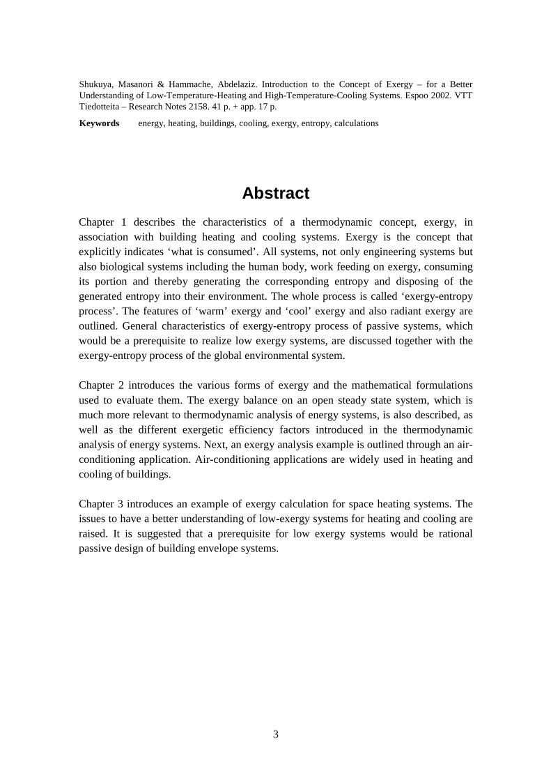
We call the process described above as exergy-entropy process (Shukuya and Komuro,1996). Table 1 shows the four fundamental steps of exergy-entropy process. Anyworking systems perform these four steps in series and cyclically. Heating and coolingsystems are no exception.
∗ There is a rather strong belief among scientists and engineers that entropy is one of the concepts whichis most difficult to understand. I think that this is not necessarily true. Those who are interested morein the concept of entropy than described here in this article should consult, for example, a book writtenby Atkins [1984], which I think best describes the characteristics of entropy.
12
Table 1. Four Steps of Exergy-Entropy Process.
1. Feed on exergy
2. Consume Exergy
3. Generate Entropy
4. Dispose of Entropy
Disposing of the generated entropy from the system makes new room for feeding on exergy andconsuming it again. Thus the process cycles.
1.2 Exergy balance equation
Let us introduce a general expression of exergy balance using the case of the above-mentioned simple building envelope system. The purpose here is to outline the structureof the exergy balance equation and we do not discuss the detailed mathematicalexpression. Those who are interested in the detailed mathematical expressions shouldrefer to Bejan (1988), Shukuya (1994), and others, in addition to Chapter 2 of thisreport.
Energy is the concept to be conserved so that the energy flowing in must be equal to thesum of the energy stored within the system and the energy flowing out from the system.This energy balance can be expressed as follows.
Since the steady-state condition is being assumed here, there is no energy storage andhence the above equation turns out to be the following simpler form.
(Energy input) = (Energy output) (1.2)
Secondly, let us set up the entropy equation consistent with the above two equations.Energy flowing into the system as heat is more or less dispersed energy. Heat is aenergy transfer due to dispersion, thus entropy necessarily flows into the system as heatflows in and some amount of entropy is generated inevitably within the system in thecourse of heat transmission. The sum of the entropy input and the entropy generatedmust be in part stored or in part flows out of the system. Therefore the entropy balanceequation can be expressed in the following form.
Since the steady-state condition is being assumed, there is no entropy storage as well asno energy storage. Therefore, the above entropy balance equation turns out to be
The fact that the outgoing entropy from the system includes the entropy generatedwithin the system suggests that the system disposes of the generated entropy with theentropy output.
Combining the energy and entropy balance equations brings about the exergy balanceequation. Entropy (or entropy rate) has a dimension of J/K (or W/K) and energy (orenergy rate) has a dimension of J (or W). Therefore we need a kind of trick to combinethe two equations.
Generally speaking, energy contained by a body, which has an ability to disperse, iscalled an energy resource. Such an energy resource exists within the environmentalspace, which is filled with dispersed energy. The dispersed energy level of the resourcesurrounded by the environmental space can be expressed as the product of the entropycontained by the resource and its environmental temperature in the Kelvin scale. Thesame expression applies to the waste discarded by the system. Therefore the entropybalance equation can be rewritten as follows.
(Entropy input) × Te + (Entropy generated) × Te = (Entropy output) × Te (1.5)
Where Te is the environmental temperature. The product of entropy and environmentaltemperature is called “anergy”, which implies dispersed energy. Using the term“anergy”, the above equation can be expressed in the following form, anergy balanceequation.
Provided that “anergy” is a portion of energy that is already dispersed, then the otherportion is not yet dispersed. Stating in another way, energy consists of two parts: thedispersed part and the part, which can disperse. The latter is “exergy”. Now let us takethe difference of the two equations, energy balance equation (1.2) and anergy balanceequation (1.6). This operation brings about
“Anergy generated” is such energy that originally had an ability to disperse and that hasjust dispersed. We can state this in the other way; that is, exergy is consumed. Anergygeneration is equivalent to exergy consumption. Using the term “exergy”, the aboveequation can be reduced to the following equation.
This is the exergy balance equation for a system under steady-state condition such as thebuilding envelope system shown in Fig. 1. Exergy consumed, which is equivalent toanergy generated, is the product of entropy generated and the environmentaltemperature.
(Exergy consumed) = (Environmental temperature) x (Entropy generated) (1.9)
Exergy consumed is exactly proportional to the entropy generated with the proportionalconstant of environmental temperature.
1.3 Warm exergy and cool exergy
The amount of exergy contained by a substance varies with its temperature and alsowith its environmental temperature. Fig. 2 shows an example of thermal exergycontained by 81 m3 (= 6m x 5m x 2.7m) of air as a function of its temperature in thecase of an environmental temperature of 288 K (=15°C). It should be noted that air has acertain amount of exergy both when the air temperature is higher than the environmentand when the air temperature is lower than the environment. Appendix A shows amathematical formula used to draw Fig. 2.
The exergy contained by air at a temperature higher than its environment is an ability ofthermal energy contained by the air to disperse into the environment. On the other hand,the exergy contained at a temperature lower than its environment is an ability of the air,in which there is a lack of thermal energy compared to the environment, to let thethermal energy in the environment flow into it. We call the former “warm” exergy andthe latter “cool” exergy (Shukuya, 1996).
15
Either “warm” exergy or “cool” exergy described above is a quantity of state containedby a substance. We have room temperature higher than the outdoor environment whenthe space is heated. In such a case room air has “warm” exergy as a quantity of state. Onthe other hand, when we have a room temperature lower than the outdoor environment,room air has “cool” exergy as a quantity of state.
80
60
40
20
0
Xr
[k
J]
3 103 0029 028 02 70
T r [K]
0 .8
0 .6
0 .4
0 .2
0 .0
xr [k
J/m3]
Tocoolwar m
Fig. 2. Thermal exergy contained by air as a function of temperature, Tr. Air volume isassumed to be 81m3 (= 6m x 5m x 2.7m). Environmental temperature, To, is 288K(=15°C). Air at a temperature higher than the environmental temperature has “cool”exergy and the air at a temperature lower than the environmental temperature has“warm” exergy (See Appendix A, formula A.1).
Thermal exergy, whether it is warm exergy or cool exergy, flows through walls, by acombination of convection, conduction, and radiation. The case shown in Fig. 1 is whenthe environmental temperature, namely outdoor temperature, is lower than the indoortemperature. In this case, “warm” exergy flows in the internal surface and out theexternal surface of the building envelope system. If the environmental temperature ishigher than the indoor temperature, namely the summer condition, the room air has“cool” exergy, which flows through the building envelope system.
The direction of energy flow changes depending on the temperature profile, whether theindoor temperature is higher or lower than the outdoor temperature, but the direction ofexergy flow is always the same from the indoors to the outdoors, external environment.What changes is whether it is “warm” exergy or “cool” exergy depending on, whetherindoor temperature is higher or lower than the outdoor temperature.
Space heating systems, whether they are low-exergy consuming or not, are the systemsthat supply and consume exergy for keeping “warm” exergy as a quantity of state
16
contained by room space in a certain desired range. Space cooling systems, on the otherhand, whether they are low-exergy consuming or not, are the systems that supply andconsume exergy for keeping “cool” exergy as a quantity of state contained by roomspace in a certain desired range. As described above, exergy consumption is alwaysaccompanied with entropy generation, thus the generated entropy must be discardedconstantly from the room space to the outdoor environment to keep “warm” or “cool”exergy within a desired range.
1.4 Radiant exergy
Radiant exergy transfer plays more important role in low-temperature-heating or high-temperature-cooling systems than in conventional air heating or cooling systems,because they require heat sources with a rather large surface area whose temperature isonly slightly higher than room air temperature.
For this reason, it would be very important to be able to evaluate radiant exergy. Fig. 3shows an example of radiant exergy emitted by a black surface of 1 m2 in the case ofenvironmental temperature of 20°C (=293 K) given by Takahashi et al. (2000).Appendix B shows a mathematical formula used to draw Fig. 3.
Supposing that there is a radiant panel of 2 m2 with a surface temperature of 40°C, thispanel emits 9 W of “warm” radiant exergy. If the surface temperature decreases from40°C to 30°C, the “warm” radiant exergy drops dramatically from 9 W down to 2 W.
In the case of cold source of the surface temperature of 6°C, the panel emits 4 W of the“cool” radiant exergy. If the surface temperature increases from 6°C to 14°C, the “cool”exergy drops dramatically from 4 W down to 0.2 W.
This suggests that low exergy systems for heating and cooling of buildings are realizedprovided that heating and cooling exergy requirements for room space is decreased bythe installation of rational building envelope systems, thus the heating and cooling isprovided at a temperature close to room temperature.
17
12
10
8
6
4
2
0R
ad
ian
t e
xe
rgy
[
W/m
2]
5 0403020100-10
Surfa ce tem p era ture [ °C ]
To
cool w a rm
Fig. 3. An example of radiant exergy emitted by a black surface of 1 m2 when theenvironmental temperature is assumed to be 293 K (20°C). A surface with atemperature lower than the environmental temperature emits “cool” radiant exergy anda surface with a temperature higher than the environmental temperature emits “warm”radiant exergy (See Appendix B, formula B.1).
1.5 Exergy-entropy process of passive systems
Here let us describe the general characteristics of six passive systems from theviewpoint of exergy-entropy process (see (Shukuya, 1998) and (Shukuya, 2000)). Assuggested above, rational passive (bio-climatic) design would be prerequisite to realizelow-exergy systems for heating and cooling.
Daylighting: this is to consume solar exergy for indoor illumination. Exergyconsumption occurs as solar exergy is absorbed by the interiorsurfaces of building envelopes. “Warm” exergy is produced as aresult of solar exergy consumption for lighting; this may beconsumed for space heating (Asada and Shukuya, 1999). Theentropy generated in the course of solar exergy consumption forlighting must be discarded into the atmosphere by ventilationcooling or mechanical cooling, hopefully by a low-exergy systemfor cooling.
Passive heating: this is to control the rate of solar exergy consumption during daytimeand nighttime by forming the built-environmental space with theappropriate materials that have low thermal conductivity and highthermal-exergy storage capacity. It is also to consume, duringnighttime, the thermal exergy produced during daytime. Most of theentropy generated is discarded spontaneously through the buildingenvelopes into the atmosphere (Shukuya and Komuro, 1996).
18
Shading: this is to let the excess solar exergy, namely the rest of exergynecessary for daylighting, be consumed before it enters the builtenvironment. It is also to reduce the entropy generated within thebuilt environment so that mechanical equipment for cooling isrequired to consume less exergy to remove the entropy generatedwithin the built environment. Exterior shading devices are verymuch attractive in this regard, since the entropy generated at thedevices is effectively discarded into the atmosphere by convection(Asada and Shukuya, 1999).
Ventilation cooling:
(Free cooling)
this is to consume kinetic exergy of atmospheric air, which isproduced by the exergy-entropy process of the globalenvironmental system described later (Shukuya and Komuro,1996), for removing the entropy generated within the builtenvironment, such as the entropy discarded from the body surfaceof the occupants and that from the lighting fixtures, electricappliances and others, into the near-ground atmosphere.
Water spraying: this is to consume the “wet” exergy contained by liquid water,which is very large compared to thermal exergy, namely “warm”or “cool” exergy, to decrease the “warm” exergy produced bysolar exergy consumption and possibly to produce “cool” exergy(See (Nishikawa and Shukuya, 1999), and (Saito and Shukuya,1998)). Roof spraying and uchimizu, which is to scatter rainwateron the road surface, are also due to this process. The consumptionof “wet” exergy to produce “cool” exergy or to decrease “warm”exergy play a very important role in photosynthetic system ofleaves (Saito and Shukuya, 1998) and the temperature-regulatingsystem of human body (Saito and Shukuya, 2000).
Composting: this is to let micro organisms consume actively a large amount ofexergy contained by garbage and hence turn it into fertilizer. The“warm” exergy produced as a result of micro-organismsconsuming chemical exergy can be rationally consumed formaintaining the temperature inside the container at a desired level.This is realized by making the walls of a container thermally wellinsulated (Takahashi and Shukuya, 1998). The entropy generatedin the process of composting is discarded into the surrounding ofthe container and finally into the near-ground atmosphere.
19
With the view of passive (bio-climatic) design as exergy-entropy process, passivedesign is to design a route in which the exergy available from our immediatesurroundings is rationally consumed and the generated entropy is rationally discardedinto the atmosphere. Again, low-exergy systems for heating and cooling would be suchsystems consistent with passive design described above.
1.6 The global environmental system
Our near-ground atmosphere receives all the entropy that is generated and discarded byall systems involving lighting, heating, and cooling of the built environment. This alsoapplies to any living systems such as bacteria, plants, and animals, since the involvedbiological phenomena can be reduced to the combination of chemical and physicalphenomena, although such reduction alone cannot give us an answer to why thebiological phenomena are so complex or how living systems evolve.
Since the entropy contained by a substance is, as described in the previous section, afunction of temperature and pressure, the near-ground atmospheric temperature mustrises if the near-ground atmosphere continues to receive the entropy discarded fromvarious systems. But, what is actually occurring in the nature is different; the averageatmospheric temperature is almost constant from year to year. This is due to the fact thatthe atmosphere has an exergy-entropy process that works feeding on and consumingsolar exergy, thereby producing the entropy, and finally disposing of the producedentropy into the Universe. We call this the global environmental system.
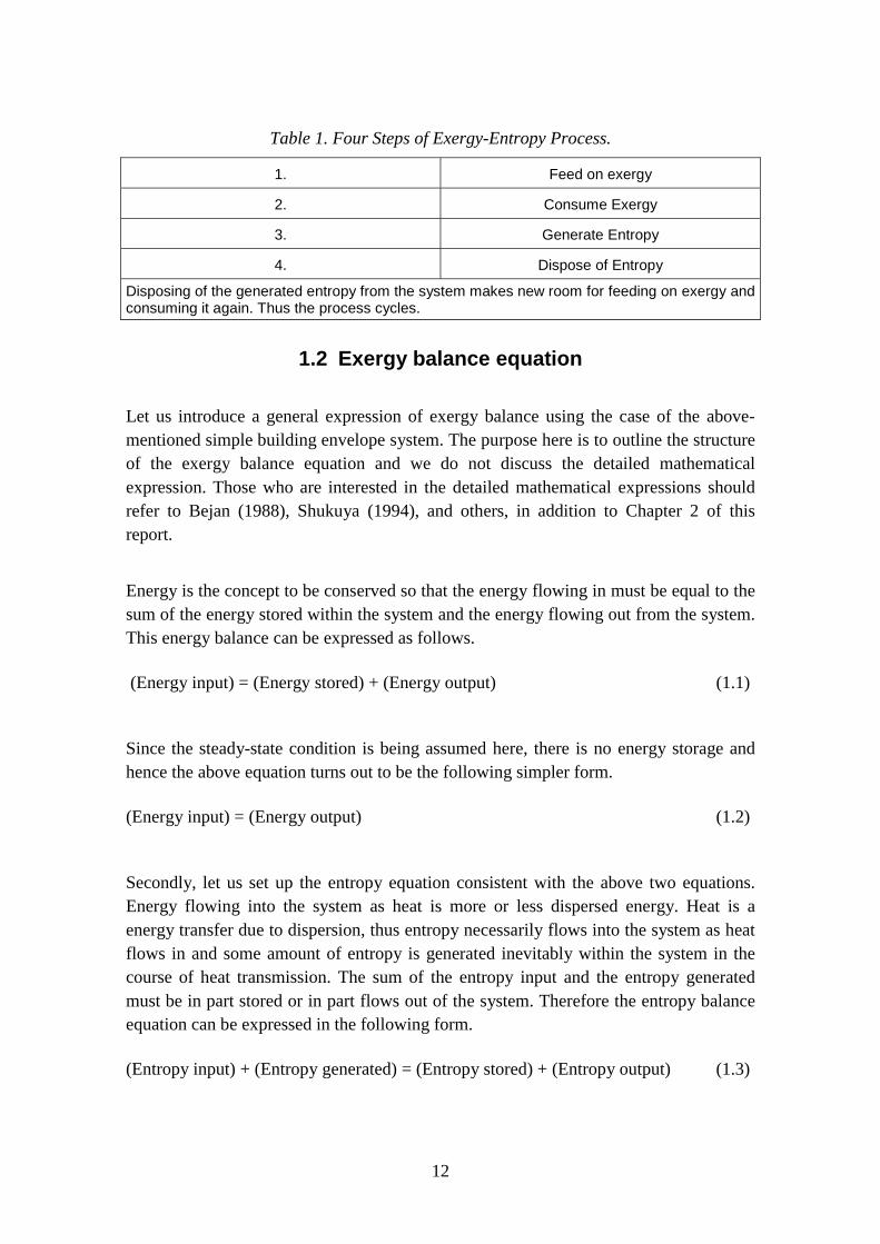
Fig. 4 shows schematically and numerically the exergy-entropy process of the globalenvironmental system (Shukuya and Komuro, 1996). The earth receives not only thesolar exergy of 220.7 W/m2 but also the “cool” radiant exergy of 102.2 W/m2 from theUniverse. These exergies are all consumed sooner or later within the upper or loweratmosphere. The figures in the squares, 176.6 W/m2 and 146.3 W/m2, show the exergyconsumption in the upper and lower atmospheres respectively. The convective aircurrent near the ground surface, a part of which can be used for ventilation, has 0.73W/m2 of kinetic exergy. The rain drops inside the clouds before falling down towardsthe ground surface have 1.25 W/m2 of potential exergy; a part of this exergy may beconsumed to produce electric power. These kinetic and potential exergies are producedby the solar and the “cool” radiant exergy consumption. The resultant generated entropydue to the exergy consumption is delivered first into the upper atmosphere byconvection, evaporation and long-wave radiation and then into the Universe by long-wave radiation. The total amount of the entropy generation is the difference between theinput and the output entropy flows across the upper boundary surface of the upper
20
atmosphere. A portion of the 102.2 W/m2 of “cool” radiant exergy coming from theUniverse enables the global environmental system to have the outgoing entropy flow of1.239 W/(m2·K). It should be recognized that the “cool” radiant exergy of 102.2 W/m2
is vitally important in addition to the solar exergy, because it is the exergy that finallysweeps away all the generated entropy within the upper and lower atmospheres, whichincludes the entropy generated by bio-climatically designed building envelope systemsand also low-exergy systems for heating and cooling.
Fig. 4. Exergy-entropy process of the global environmental system. The drawing on thetop is the exergy input, output, and consumption in W/m2. The other drawing on thebottom is the entropy input, output, and generation in W/(m2·K). The amounts of theexergy consumption and the entropy generation are indicated by the figures in thesquares.
1.7 Conclusion
A thermodynamic concept of exergy which explicitly indicates “what is consumed” wasexplained from the viewpoint of its application especially to describing building heatingand cooling systems, together with an explanation of entropy, which explicitly indicates“what is disposed of”.
21
All working systems work as exergy-entropy process, in which exergy is supplied, aportion is consumed and thereby the resultant entropy is generated, and finally thegenerated entropy is discarded into the environment. The structure and function of theexergy balance equation were outlined, and the features of “warm” exergy and “cool”exergy were presented. The general characteristics of the exergy-entropy process ofpassive design were also described together with the global environmental system. Whatis suggested from the discussion here is that rational passive design is a prerequisite torealize low exergy systems for the heating and cooling of buildings.
22
2. Mathematical formulationsAbdelaziz Hammache
2.1 Introduction
Traditional methods of thermal system analysis are based on the first law ofthermodynamics. These methods use an energy balance on the system to determine heattransfer between the system and its environment. The first law of thermodynamicsintroduces the concept of energy conservation, which states that energy entering athermal system with fuel, electricity, flowing streams of matter, and so on is conservedand cannot be destroyed. In general, energy balances provide no information on thequality or grades of energy crossing the thermal system boundary and no informationabout internal losses. By contrast, the second law of thermodynamics introduces theuseful concept of exergy in the analysis of thermal systems. Exergy is a measure of thequality or grade of energy and it can be destroyed in the thermal system. The secondlaw states that part of the exergy entering a thermal system with fuel, electricity,flowing streams of matter, and so on is destroyed within the system due toirreversibilities. The second law of thermodynamics uses an exergy balance for theanalysis and the design of thermal systems. The second part of this document describesthe various forms of exergy and the mathematical formulations used to carry out theexergy balance. The different exergetic efficiency factors are also introduced andexplained.
2.2 Exergy balance
One of the main uses of the exergy concept is in an exergy balance in the analysis ofthermal systems.
The exergy balance is a statement of the law of degradation of energy. Degradation ofenergy is due to the irreversibilities of all real processes. Because open system analysisis much more relevant to the analysis of thermal plants or chemical systems than closedsystem analysis, the exergy balance of an open steady state system, as shown in Fig. 5,is presented. The exergy balance is stated around a control region delimited by specificboundaries.
23
Control region
0≥•
I
Shaft work
shW•
iE•
oE•
Inpu
t of m
atte
r
Out
put o
f mat
ter
Surface Control11 ,TQ•
22 ,TQ•
rr TQ ,•
,....,,, 2,01,000 xxTQ•
Environment
00 =• Q
E
Thermal energy reservoirs � ���
����
�−=
••
r rr
Q
TTQE 01
Fig. 5. Steady state process in an open control region.
•∗•∗•++=+ IWEEE sho
Qi
(2.1)
where:
ii
ii emE �••
=(2.2)
oo
oo emE �••
=(2.3)
���
����
�−=�
••
rrr
Q
TT
QE 01(2.4)
The expression for specific exergy is written as:
0
20
00 2)()( gZ
CessThhe cho +++−−−=
(2.5)
The exergy flow to the control region is always greater that that from the control region.The difference between the two, the rate of loss of exergy, is called the irreversibility
24
rate. The irreversibility rate is calculated from the Gouy-Stodola relation, which statesthat the irreversibility rate of a process is the product of the entropy generation rate forall systems participating in the process and the temperature of the environment.
���
�
�
���
�
�−−== ���
•••••
r r
ri
ii
oogen
TQ
smsmTSTI 000
(2.6)
The various exergy terms, which go into the exergy balance, are presented in Appendix C.
2.3 Definitions of exergetic efficiencies
Three definitions of exergetic efficiencies for steady state processes are found in theliterature. These are the conventional or simple exergetic efficiency, the rationalexergetic efficiency and the utilizable exergy coefficient.
2.3.1 Conventional exergetic efficiency
The simplest form of exergetic efficiency is the conventional exergetic efficiency. Forthe formulation of this efficiency the exergy balance for the incoming and outgoingflows is set up, where I is the irreversibility.
•••+= IEE outin
(2.7)
Referring to Fig. 1:
∗••+= Q
iin EEE(2.8)
∗••+= shoout WEE
(2.9)
The traditional exergetic efficiency is the ratio of the total outgoing exergy flow to thetotal incoming exergy flow:
25
in
out
E
E•
•
=η(2.10)
This is an unambiguous definition and can be used for all process plants and units.Unfortunately, it gives a good impression of the thermodynamic perfection of a systemonly when all the components of the incoming exergy flow are transformed to othercomponents, e.g., in the case for power stations or for building heating and coolingsystems. The traditional exergetic efficiency for power stations is expressed as:
fuel
elec
E
W•
•
=η(2.11)
When all the components of the incoming exergy flows are not transformed to othercomponent, the untransformed components give a false impression of the performanceof the process plant or unit. For example, if we consider a chemical reactor with a zeroreactive conversion factor, the input exergy rate will equal the output exergy rate andthe traditional exergetic efficiency will equal 1. There are no irreversibilities in thereactor but it does not produce anything! In this case, the traditional exergetic efficiencygives a false impression of the thermodynamic performance of the reactor. To solve thisproblem other exergetic efficiencies have been proposed.
2.3.2 Rational exergetic efficiency
The rational exergetic efficiency is defined by Kotas (1985) as a ratio of the desiredexergy output to the exergy used or consumed.
usedused
outputdesired
E
I
E
E•
•
•
•
−== 1ψ(2.12)
outputdesiredE•
is the sum of all exergy transfers from the system, which must be regardedas constituting the desired output, plus any by-product, which is produced by thesystem. The desired output is determined by examining the function of the system.
usedE•
is the required exergy consumed for the process to be performed.
The rational efficiency can be applied to any system, except to purely dissipativesystems, because no desired product can be defined in this case.
26
As an example of formulation of rational efficiency consider the refrigeration plantevaporator shown in Fig. 6 (Kotas, 1985).
Cold Chamber
LT LQ•
1
•E 2
•E
Fig. 6. Refrigeration plant evaporator.
The cold chamber may be considered as a thermal energy reservoir at a temperatureTL<T0. Referring to Fig. 6, the exergy balance for the control region indicated by thedashed contour may be written:
���
����
�−−=−�
�
���
� −••••
L
0L21
TT
1QIEE(2.13)
The desired output is the increase in the exergy of the cold chamber, which since TL<T0,is associated with heat transfer from the cold chamber. Thus:
���
����
�−−=
••
LLoutputdesired
TT
QE 01(2.14)
By incorporating Eqs. (13) and (14) into Eq. (12), the rational efficiency for this systemis expressed as:
2121
0
11
••
•
••
•
−−=
−
���
����
�−
=EE
I
EE
TT
QL
L
ψ
(2.15)
and the irreversibility rate is:
27
��
�
�
��
�
�−�
�
�
� −=•
•••
L
L
TQ
SSTI 120
(2.16)
2.3.3 Utilizable exergy coefficient
Brodyansky, Sorin and LeGoff (1994) introduced this form of exergetic efficiency,called utilizable exergy coefficient. This form of efficiency is an improvement on thetraditional exergetic efficiency, because it subtracts the untransformed components fromthe incoming and outgoing streams. The following section introduces this concept.
To any material, heat and work stream can be associated an exergy content, which iscompletely defined by temperature, pressure and composition of the stream itself and ofa reference state, which is normally the environment in which the system operates. It is,therefore, possible to compute the exergy content of all incoming and outgoing streamsto and from a system and to establish an overall exergy balance over any system, asshown in Fig. 7. The total exergy input, Ein, of a real system is always higher than itsexergy output, E", because a certain amount of exergy is irreversibly destroyed withinthe system. This exergy, generally referred to as the internal exergy losses or exergydestruction, Iint is directly linked to the thermodynamic irreversibilities in the system.
Exer
gy In
put,
E in
Con
sum
ed E
xerg
y, E
c
Exer
gy O
utpu
t, E"
Internal ExergyLosses (Iint)
External ExergyLosses (Iext)
Transiting Exergy, Etr
Produced UtilizableExergy, Epu
Util
izab
le E
xerg
y, E
out
ProducedExergy, Ep
Fig. 7. Graphical presentation of overall exergy balance.
28
As illustrated in Fig. 7, part of the exergy output from the system may dissipate into theenvironment as heat losses, sewage waste or smokestack effluents, for example. Thiswasted exergy, no longer usable by subsequent processes, constitutes the externallosses, Iext. It is more appropriate, from the standpoint of downstream operations, toconsider the exergy that remains utilizable, Eu, rather than the total output, E". Only partof the utilizable exergy is produced by the system through the physicochemicalphenomena that take place within its boundaries. The rest of the exergy that leaves thesystem with the utilizable exergy stream is a part of the exergy input, which has simplygone through the system without undergoing any transformation. This fundamental factwas first recognized by Kostenko (1983), who gave the name transiting exergy, Etr, tothis fraction of the exergy supplied to a system. Typically in a chemical reactor, part(but not all, because of temperature and pressure changes) of the exergy associated withunreacted feed or inerts would constitute transiting exergy. Transiting exergy wasfurther characterized and algorithms have been developed for computing it directly(Sorin and Brodyansky, 1985; Brodyansky et al. 1994). On the basis of theseobservations a new coefficient of thermodynamic efficiency, the utilizable exergycoefficient, ηu, has been defined (Sorin et al., 1998).
The exergetic efficiency with transiting exergy is defined as follows:
c
pu
trin
trextin
trin
troutu
E
E
EE
EIIE
EE
EE•
•
••
••••
••
••
=−
−−−=−
−= intη(2.17)
where trE•
is the transiting exergy rate, puE•
is the produced utilizable exergy rate andcE
• is the consumed exergy rate.
As has been demonstrated by Sorin and co-workers (1998), the decrease in the transitingexergy, trE
•, improves the conversion performance of the system. The utilizable exergy
coefficient decreases as int
•I , extI
• and trE
• decrease.
An example on the use of the various exergetic definitions is shown in Appendix D.
2.4 Air-conditioning applications
Air-conditioning applications are important and widely used in heating and cooling ofbuildings. This section presents the use of the concept of exergy in the assessment ofair-conditioning applications. The concepts of physical exergy and chemical exergy
29
play an important role in assessing the true thermodynamic merit of air-conditioningapplications.
The objective of most air-conditioning applications is to bring a humid air mixture to astate (temperature and composition) that differs from the conditions found in theatmospheric air.
The classical way of describing the thermodynamic properties of humid air is to view itas a perfect gas mixture of dry air (a) and water vapor (v) (Table 2). The ideal gasconstants of these two components are the values corresponding to T ≅ 300 K and thelow-pressure limit (Bejan, 1988).
Table 2. Ideal gas constants of dry air (a) and water vapor (v).
Dry Air (a) Water Vapor (v)
).(. KkgkJ2870Ra = ).(. KkgkJ46150Rv =
).(., KkgkJ0031c ap = ).(., KkgkJ8721c vp =
kmolkg9728M a .= kmolkg01518M v .=
).(. KkmolkJ3148R = ).(. KkmolkJ3148R =
).(., KkmolkJ05729c ap = ).(., KkmolkJ72433c vp =
The state of any humid air is specified by its temperature T, its pressure P, and one ofthe mole fraction xa or xv since 1xx va =+ .
The composition of humid air is described in the field of air conditioning by differentways:
The mass ratio called specific humidity or humidity ratio, ω, which represents thenumber of kilograms of water to 1 kg of dry air in the given mixture :
a
v
mm
=ω(2.18)
30
The mole fraction ratio, ϖ, which represents the number of moles of watercorresponding to 1 mole of dry air in the given mixture :
a
v
xx
=ω(2.19)
The relative humidity, φ, which represents the number moles of water in the actualmixture over the number of moles of water in the saturated mixture at temperature T :
[ ][ ] )(,
,
, TPP
PTxPTx
sat
v
satsatv
v ==φ(2.20)
The specific total flow exergy of humid air is deduced from the definition of thephysical flow exergy applied to a mixture of ideal gases. It can be expressed differentlydepending on how the composition of humid air is described (Bejan, 1988):
The specific total flow exergy per mole of a humid air mixture is:
( )��
�
�
��
�
�+++��
�
����
�−−+=
v0
vv
a0
aa0
00
000vpvapat
xx
xxx
xTRPPTR
TT1
TTTcxcxe
,,
,, lnlnlnln(2.21)
where, subscript 0 indicates ambient properties.
Two alternative versions of this equation are used for engineering calculations. The firstalternative uses the mole ratios ϖ and ϖ0 to describe the composition of the actual andthe ambient air mixtures:
( ) ���
����
�
++
+++++��
�
����
�−−
++=
0
00
00
000
vpapt
1111TR
PPTR
TT1
TTT
1cce
ωω
ωω
ωωω
ωω lnlnlnln,,
(2.22)
The second alternative reports the specific total flow exergy per kilogram of dry air:
( ) ���
����
�
++
+++++��
�
����
�−−
++=
0
00
00
000
vpapt
1111TR
PPTR
TT1
TTT
1cce
ωω
ωω
ωωω
ωω lnlnlnln,,
(2.23)
31
(2.24)
( ) ( ) ( ) ���
����
�+
++++++��
�
����
�−−+=
0
00
00
000,, ln
11ln1ln1ln1
ωωω
ωωωωω TR
PPTR
TT
TTTcce aavpapt
The specific total flow exergy of dry air is deduced by setting ω and ϖ to zero.
( )00a0
0a00
0apat 1TRPPTR
TT1
TTTce ω+++��
�
����
�−−= lnlnln,,
(2.25)
The specific total flow exergy of liquid water is also required for the case of exergyanalysis of air-conditioning applications. The specific total flow exergy per kilogram ofliquid water, w, yields:
where the partial pressure of water vapor in atmospheric air is given by:
0v0w0 PxP ,, = (2.27)
The total flow exergy of liquid water can be approximated by using the properties ofrespective neighboring states on the two-phase dome of the Mollier chart (Bejan, 1988):
Which means that the evaporating cooling process due to thermodynamic irreversibilitydestroys two thirds of the exergy brought to the control volume.
One important observation that must be dealt with is that the choice of the ambientconditions affects quite strongly the numerical results of the exergy analysis. The choiceof P0 = 1 atm is quite obvious, however there is a lack of a convention for the selectionof T0 and φ0. Fig. 9 shows how the numerical results of the exergy efficiency areaffected by the selection of T0 and φ0.
36
Second Law Efficiency, Φ 0 = 0.6
0.30.32
0.34
0.360.38
0.40.42
20 21 22 23 24 25 26 27 28 29 30
Ambiant Temperature, T0 (0C)
Exer
gy e
ffici
ency
Second Law Efficiency, T0 = 25 0C
0
0.1
0.2
0.3
0.4
0.5
0 0.2 0.4 0.6 0.8 1
Relative humidity, Φ 0
Exer
gy e
ffici
ency
Fig. 9. Exergy efficiency of the adiabatic evaporative cooling process as a function of φ0
and T0.
2.5 Conclusion
The exergy analysis of a thermal energy system has been presented through the exergybalance of an open system. The mathematical formulations of the various forms ofexergy and the exergy efficiency factors were presented. Few examples were alsopresented to illustrate the use of the mathematical formulation. In the context of spaceheating and cooling in buildings, it is obvious that the use of either a conventional or arational exergetic efficiency is sufficient to compare between different heating andcooling systems since no chemical reactions are involved in heating and coolingapplications.
37
3. Space heating exampleMasanori Shukuya and Abdelaziz Hammache
3.1 An example of heating exergy calculation
Let us compare three numerical examples of exergy consumption during the wholeprocess of space heating from the power plant, through the boiler to the buildingenvelope in the steady state as shown in Fig. 10 (Shukuya, 1994). Case 1 assumes thatthe thermal insulation of the building envelope system is poor; that is, single windowglazing and an exterior wall with only a thin insulation board, and a boiler with amoderate thermal efficiency. Case 2 meanwhile assumes that the thermal insulation ofthe building envelope is improved by a combination of double window glazing and anexterior wall with improved insulation, while the boiler efficiency remains unchanged.Case 3 assumes in addition that the boiler efficiency is improved to near its limit. Table3 summarizes the assumptions for calculation in three Cases.
Fig. 10. A space heating system assumed for example calculation of exergyconsumption.
Fig. 11 shows respective three series of exergy input, exergy consumption, and exergyoutput from the boiler, to the water-to-air heat exchanger, to the room air, and finally tothe building envelope in three Cases.
Exergy consumption within the boiler system is the largest among the sub-systems.Consuming a lot of exergy is unavoidable when extracting thermal exergy by acombustion process from the chemical exergy contained in LNG. Because of this, onemay consider that the improvement of boiler efficiency is essential. The dashed lineindicated below Case 1 shows the result of the improvement of boiler efficiency from0.8 to 0.95 in Case 1. The decrease of exergy consumption is marginal. One may, then,consider that increasing the outlet water temperature of the boiler makes exergy output
38
from the boiler larger and hence the boiler more efficient. This, however, results in theconsumption of more exergy within the water-to-air heat exchanger and also within theroom air, in which the required temperature is 293 K (20°C). These facts imply that anextremely high boiler efficiency alone cannot necessarily make a significantcontribution to reducing exergy consumption in a whole process of space heating.
Table 3. Assumptions for example calculation of exergy consumption.
Case Heat loss coefficient of building envelope Thermal efficiency of boiler
1 108.7 W/K (3.0 W/m2 K) 80 %
2 57.1 (1.59) 80
3 57.1 (1.59) 95
Heat-loss-coefficient values in the brackets are those per unit floor area. A 6.0m x 6.0m x 3.0mroom with one exterior wall having a 1.5m x 6m glazed window is assumed. The exterior-windowand –wall U values are 6.2 and 2.67 W/m2K for Case 1; 3.6 and 1.14 for Cases 2 and 3. Thenumber of air changes due to infiltration is 0.8 h-1 for Case 1; and 0.4 h-1 for Cases 2 and 3. Theroom air temperature is ideally controlled and kept constant at 293 K (20°C) in all cases while theoutdoor air temperature is assumed to be constant at 273 K (0°C). Outlet air temperature, inletand outlet water temperatures of the heat exchanger are assumed to be 303 K (30°C), 343 K(70°C), and 333 K (60°C), respectively, for all Cases. The rates of electric power supplied to a fanand a pump are 30 W and 23 W in Case 1; 16 W and 12 W in Cases 2 and 3. The ratio of thechemical exergy to the higher heating value of liquidified natural gas (LNG) is 0.94. The thermalefficiency of the power plant, that is, the ratio of produced electricity to the higher heating value ofLNG supplied is 0.35.
3 00 0
2 50 0
2 00 0
1 50 0
1 00 0
50 0
0
Ex
erg
y
[W]
43210 Boiler H ea t exch a n g er
Room a ir Bu ild in gen velop e
Sp a ce Hea tin gExerg y Loa d
Ca se 2
Ca se 1
Ca se 3
Fig. 11. A comparison of exergy consumption for four stages of the space heatingsystems. Exergy consumption is the difference in exergy between input and output; forexample, in Case 1, 2554 W of exergy is supplied to the boiler and 420 W of “warm”exergy is produced and delivered to the heat exchanger by hot water circulation so thattheir difference, namely 2134 W (=2554-420), is consumed inside the boiler.
39
The heating exergy load, which is the exergy output from the room air and the exergyinput to the building envelope is 148 W in Case 1 and 78 W in Case 2 and 3. It is only 6to 7 % of the chemical exergy input to the boiler so that one may regard a measurereducing the heating exergy load as marginal. But, as can be seen from the difference inthe whole exergy consumption profile between Case 1 and Case 2, it is more beneficialto reduce the heating exergy load by installing thermally well-insulated glazing andexterior walls than to develop a boiler with an extremely-high thermal efficiency, inorder to decrease the rate of total exergy consumption. The reduction in exergyconsumption of the boiler sub-system indicated by the difference between Case 2 andCase 3 due to the improvement in boiler efficiency turns essentially meaningful togetherwith the improvement of building-envelope thermal insulation.
Those interested in numerical calculation of the example explained above areencouraged to consult Appendix E, which describes the detailed calculation procedureto obtain Fig. 2.
3.2 Conclusion
A few examples of exergy calculations were presented. What is suggested from thediscussion here is that rational passive design is a prerequisite to realize low exergysystems for the heating and cooling of buildings.
40
ReferencesAsada, H. and Shukuya, M. 1999. ‘Numerical Analysis of Annual Exergy Consumptionfor Daylighting, Electric-Lighting, and Space Heating/Cooling System’. SixthInternational IBPSA Conference (BS'99), Kyoto Japan. Pp. 121-127.
Atkins, P. W. 1984. ‘The Second Law’, Scientific American Library.
Bejan, A. 1988. Advanced Engineering Thermodynamics, A Wiley – IntersciencePublication, John Wiley & Sons.
Brodyansky, V. M., Sorin, V. M. and LeGoff, P. 1994. The Efficiency of IndustrialProcesses: Exergy Analysis and Optimization. Elsevier.
Cornelissen, R. L. 1997. Thermodynamics and Sustainable Development: The Use ofExergy Analysis and the Reduction of Irreversibility, PhD Thesis, University of Twente,Netherlands.
Kostenko, G. 1983. Efficiency of Heat Processes. Promishlenaya Teplotechnika, No. 4,pp. 70–73 (in Russian).
Kotas, T. J. 1985. ‘The Exergy Method of Thermal Plant Analysis’. Butterworths:Anchor Brendon Ltd.
Nishikawa, R. and Shukuya, M. 1996. ‘A Calculation of the Exergy-Entropy Process ofEvaporative Cooling’. Journal of Architectural Planning and EnvironmentalEngineering, Architectural Institute of Japan, No. 489, pp. 47–55 (in Japanese withEnglish abstract).
Nishikawa, R. and Shukuya, M. 1999. ‘Numerical Analysis on the Production of CoolExergy by Making Use of Heat Capacity of Building Envelopes’. Sixth InternationalIBPSA Conference (BS'99), Kyoto Japan, Pp. 129–135.
Saito, M. and Shukuya, M. 1998. ‘Numerical Analysis of Exergy Balance of a Leaf’,Journal of Architectural Planning and Environmental Engineering, ArchitecturalInstitute of Japan, No. 505, pp. 51–58 (in Japanese with English abstract).
Saito, M. and Shukuya, M. 2000. ‘Exergy Balance of Human Body and ThermalComfort’. Journal of Architectural Planning and Environmental Engineering,Architectural Institute of Japan, No. 535, pp. 17–23 (in Japanese with English abstract).
41
Schrödinger, E. 1945. ‘What is Life?’ Cambridge, (reprinted in 1967).
Shukuya. M. and Komuro. D. 1996. ‘Exergy-Entropy Process of Passive Solar Heatingand Global Environmental Systems’. Solar Energy, Vol. 58, Nos 1–3, pp. 25–32.
Shukuya, M. 1994. ‘Energy, Entropy, Exergy and Space Heating Systems’. Proceedingsof the 3rd International Conference "Healthy Buildings '94", Vol. 1, pp. 369–374.
Shukuya, M. 1996. ‘Warm exergy and cool exergy’. Proceedings of Annual Meeting,Building Science Section, Architectural Institute of Japan. Pp. 453–454 (in Japanese).
Shukuya, M. 1998. ‘Bio-climatic Design as Rational Design of Exergy-EntropyProcess’. Proceedings of Passive and Low Energy Architecture (PLEA) '98. Lisboa,Portugal. Pp. 321–324.
Shukuya, M. 2000. ‘Design with Natural Potentials’. Sustainable Architecture in Japan:The Green Buildings of Nikken Sekkei, Wiley-Academy. Pp. 140–144.
Sorin, M. V. and Brodyansky, V. M. 1985. ‘A Method for Efficient Definition for PowerTechnological Systems’. Izvestia Vuzov Energetika, 3, pp. 78–88 (in Russian).
Sorin M. V., Lambert, J. and Paris, J. 1998. ‘Exergy Flows Analysis in ChemicalReactors’. Trans. IChemE, 76( Part A); pp. 389–395.
Szargut, J., Morris, D. R. and Stewart, F. R. 1988. ‘Exergy Analysis of Thermal,Chemical and Metallurgical Processes’. Hemisphere Publishing Corporation.
Takahashi, I. and Shukuya, M. 1998. ‘An Experimental Study on the Effect of ThermalInsulation on Fermentation Process in Residential Composting Tanks’. Journal ofArchitectural Planning and Environmental Engineering, Architectural Institute of Japan,No. 503, pp. 25–32 (in Japanese with English abstract).
Takahashi, I., Kondo, D., Isawa, K. and Shukuya, M. 2000. ‘Calculation of RadiantExergy’. Proceedings of Annual Meeting, Building Science Section, ArchitecturalInstitute of Japan, pp. 487–488 (in Japanese).
A1
Appendix A: Thermal exergy contained by avolume of room air
���
���
−−=o
roorraairra T
TTTTmcX ln)((A.1)
where Xra is thermal exergy contained by a volume of room air [kJ], cair is specific heatof air [kJ/(kg·K)], mra is mass of room air [kg], Tr is room air temperature in the Kelvinscale, and To is outdoor air temperature in the Kelvin scale, which is the environmentaltemperature for room space. The value of cair is assumed to be 1.005 kJ/(kg·K); mra to be97.2 kg (= 1.2 kg/m3 x 6m x 5m x 2.7m); and To to be 288 K (= 15°C).
B1
Appendix B: Radiant thermal exergy emitted by awall surface
���
��� −−−= )(
34)( 3344
osoosrad TTTTTx εσ(B.1)
where xrad is radiant thermal exergy emitted by a wall surface of unit area [W/m2], ε isemittance of the surface, σ is Stephan-Boltzmann constant [W/(m2·K)] (5.67 x 10⁻⁸), Ts
is surface temperature in the Kelvin scale, and To is outdoor air temperature in theKelvin scale, which is the environmental temperature for room space. The value of To isassumed to be 293 K (20°C) and ε to be unity, namely black surface.
C1
Appendix C: Forms of exergy
Exergy related to work transfer
Because exergy is defined as the maximum work potential, the work transfer rate, •
W , isequivalent to the exergy transfer rate, WE
•
, in every respect.
••= WEW
(C.1)
Exergy related to heat transfer
Assuming a uniform temperature distribution in a thermal energy reservoir, the exergytransfer rate,
Q
E•
, connected with the hear transfer rate, Q , can be calculated by thefollowing formula:
τ×=••QE
Q (C.2)
where TT01−=τ is a non-dimensional exergetic temperature, 0T is the ambient
temperature, which is set to 298 K (Szargut et al, 1988) and T is the heat sourcetemperature.
Exergy related to a stream flow in steady state
Exergy transfer rate associated with material streams can be calculated with thefollowing formula:
•••••+++= chphpk EEEEE
(C.3)
where:
��
���
�= 20CmEk represents the kinetic exergy rate, where 0C is the speed of the stream
flow relative to the earth surface.
C2
0gZmE p
••= represents the potential exergy rate, where g is the earth gravity and 0Z
the stream altitude above the sea level.
•
phE represents the thermomechanical exergy based on the temperature and the pressureof the stream.
•
chE represents the chemical exergy based on the chemical potentials of the componentsin the stream.
The specific exergy is written as:
chphpk eeeee +++= (C.4)
where •
•
=m
Ee and •m is the mass flowrate of the stream.
Physical exergy
Physical exergy, known also as thermomechanical exergy, is the work obtainable bytaking the substance through reversible process from its initial state (T, P) to the state ofthe environment (T0, P0). The specific physical exergy is written as:
)()( 000 ssThheph −−−= (C.5)
For a perfect gas with a constant pc :
���
����
�−−−=
0000 lnln)(
PPR
TTcTTTce ppph
(C.6)
For solids and liquids when assuming a constant specific heat c:
( )00
00 ln)( PPvTTTTTce mph −−�
�
���
����
�
�−−=
(C.7)
Where mv is the specific volume, determined at temperature T0.
C3
Chemical exergy
Chemical exergy is equal to the maximum amount of work obtainable when thesubstance under consideration is brought from the environmental state (T0, P0) to thedead state (T0, P0, µ0i) by processes involving heat transfer and exchange of substancesonly with the environment. The specific chemical exergy ech at P0 can be calculated bybringing the pure component in chemical equilibrium with the environment.
For pure reference components, which also exist in the environment, the chemicalexergy consist of the exergy, which can be obtained by diffusing the components totheir reference concentration P00. The specific molar chemical exergy of a referencecomponent i present in the environment at partial pressure iP ,00 is:
ii P
PRTe
,00
000 ln=
(C.8)
When a substance does not exist in the reference environment, it must first react toreference substances in order to get in equilibrium with the environment. The reactionexergy at reference conditions equals the standard Gibbs energy change. So the overallspecific chemical exergy term becomes:
� ∆−=j
irjjich gee 0, ν (C.9)
The chemical exergy of a gaseous mixture or a mixture of ideal liquids is given by:
( )[ ]iii
ich xRTexe ln00 +=� (C.10)
ix represents the molar fraction of component i and ie0 its standard chemical exergy.
The chemical exergy of real solutions can be computed from:
( )[ ]iiii
ich xRTexe γln00 +=� (C.11)
where iγ if the activity coefficient of the component i .
C4
The chemical exergies of gaseous fuels are computed from the stoichiometriccombustion chemical reactions. The standard chemical exergies of various fuels arepublished in the literature (e.g. Kotas (1985), Bejan (1988)).
For many fuels, the chemical exergy can be estimated on the basis of the NetCombustion Value (NCV). The relation between the NCV and the chemical exergy is:
NCVech •= φ (C.12)
where φ can be calculated with formulas based on the atomic composition. For differentfuel oils and petrol φ is between 1.04 and 1.08.
D1
Appendix D: Example of exergetic efficiencies
Air separation example
The application of the three different forms of efficiencies will be shown on an airdistillation column (Cornelissen, 1997), which is shown in Fig. D.1.
M
HEATX
VALVEC
OLU
MN
D
B
COLD
Fig. D.1. Air distillation column.
The incoming mixture M is first cooled by the reboiler and cooled further by thethrottling process. The incoming and outgoing flows are vapors and assumed to beperfect gases. The properties and exergy of the streams are shown in Table D.1.
Table D.1. Table of properties and exergy of the streams.
Stream T
(K)
P
(MPa)
Flow rate
(kmol/h)
Composition
(mole %)
O2 N2
Chemicalexergy
(kW)
Physicalexergy
(kW)
Totalexergy
(kW)
M 139 4 7 21 79 0 23.83 23.83
B 90 0.1 1 99 1 1.03 1.23 2.26
D 79 0.1 6 10 90 0.18 8.6 8.78
The column is assumed to operate adiabatically. The composition of air in theenvironment has been assumed to be 0.21 O2 and 0.79 N2 fractions by mole and theactivity coefficients are taken all to be 1. The environmental temperature T0 andpressure P0 are assumed to be 298 K and 0.10 MPa, respectively.
D2
Conventional exergetic efficiency
463.083.23
78.826.2 =+=+== •
••
•
•
M
DB
in
out
E
EE
E
Eη(D.1)
Rational exergetic efficiency
Depending on the desired output two cases have been discussed.
In case (i), the desired output is considered to be the increase in chemical exergy. Thus:
0864.0)60.823.1(83.23
18.003.1 =+−
+=
��
���
�+−
−+==•••
•••
•−
•
ph
D
ph
B
ph
M
ch
M
ch
D
ch
B
used
outputdesired
EEE
EEE
E
Eψ(D.2)
In case (ii), the desired output is considered to be the increase in both the chemicalexergy and the thermal component of exergy.
271.0=
��
���
�+−
���
�
�−++��
�
�
�−+
==ƥƥƥ
∆•∆•∆••••
•−
•
P
D
P
B
P
M
T
M
T
D
T
B
ch
M
ch
D
ch
B
used
outputdesired
EEE
EEEEEE
E
Eψ
(D.3)
The thermal and mechanical exergy components of streams M, B and D can becomputed using the relations for perfect gases using constant cp values.
Utilizable exergy coefficient
To compute the utilizable exergy coefficient, the transiting exergy in the differentcomponents must be calculated using the algorithms found in Sorin and Brodyansky,1985 or Brodyansky et al. 1994.
The transiting chemical exergy in each part of the stream is:
D3
[ ] [ ]( ) ( )222222 ;min;min)(NB
OMB
NB
NM
OB
OMB
ch
BMtr eeneeeenE +=+=••
−
• (D.4)
[ ] [ ]( ) ( )222222 ;min;min)(NM
ODD
ND
NM
OD
OMD
ch
DMtr eeneeeenE +=+=••
−
• (D.5)
The transiting physical components of exergy in each part of the stream is:
( ) ( )[ ] ( )MBBBMBBMBMB
ph
BMtr TpenTpeTpenE ,,;,min)(
••
−
•==
(D.6)
( ) ( )[ ] ( )MDDDMDDMDMD
ph
DMtr TpenTpeTpenE ,,;,min)(
••
−
•==
(D.7)
The chemical exergy change for the output streams B and D is given by:
( ) ( ) ( ) ( ) 2222222222 NDD
OBB
OD
NMD
NB
OMB
ND
ODD
NB
OBB
ch
out eneneeneeneeneenE•••••••
+=+−+−+++=∆(D.8)
since : 022 == NM
OM ee
The physical exergy change for the output streams B and D is given by:
( ) ( )( ) ( ) ( )( )MDDDDDDMBBBBBB
ph
out TpeTpenTpeTpenE ,,,, −+−=∆••• (D.9)
which is the increase in the thermal component of exergy of flow B at pressure pB andin the thermal component of exergy of flow D at pressure PD.
The chemical exergy change for the input stream M is given by:
( ) ( ) ( ) 22222222 ODD
NBB
NM
ODD
NB
OMB
NM
OMM
ch
in eneneeneeneenE••••••
−−=+−+−+=∆(D.10)
since : 022 == NM
OM ee
The physical exergy change for the input stream M is given by:
( ) ( )( ) ( ) ( )( )MDDMMMDMBBMMMB
ph
in TpeTpenTpeTpenE ,,,, −+−=∆••• (D.11)
which is the reduction of exergy flows in the system caused by the pressure drop attemperature TM.
D4
Using data from Table D1, the utilizable exergy coefficient, ηe, for the air separationexample can now be calculated:
369.0=∆+∆
∆+∆=••
••
ph
in
ch
in
ph
out
ch
outu
EE
EEη(D.12)
If we compare, the three exergetic efficiencies, It is seen that the traditional exergeticefficiency gives the highest efficiency compared to the other efficiencies. However, ifthe chemical exergy of the mixture was much higher as in crude oil separation, theconventional exergetic efficiency would be close to unity. Therefore, the conventionalexergetic efficiency is of little use and may lead to false conclusions. The rationalefficiency is easy to apply, however, to define the desired output exergy and the usedexergy for a unit it is necessary to be clear about the function of the unit in the contextof the plant. The utilizable exergy coefficient, on the other hand, is a straightforwardmethod for an appropriate definition of efficiency, which gives an unambiguous answer.
E1
Appendix E: Exergy calculationfor space heating
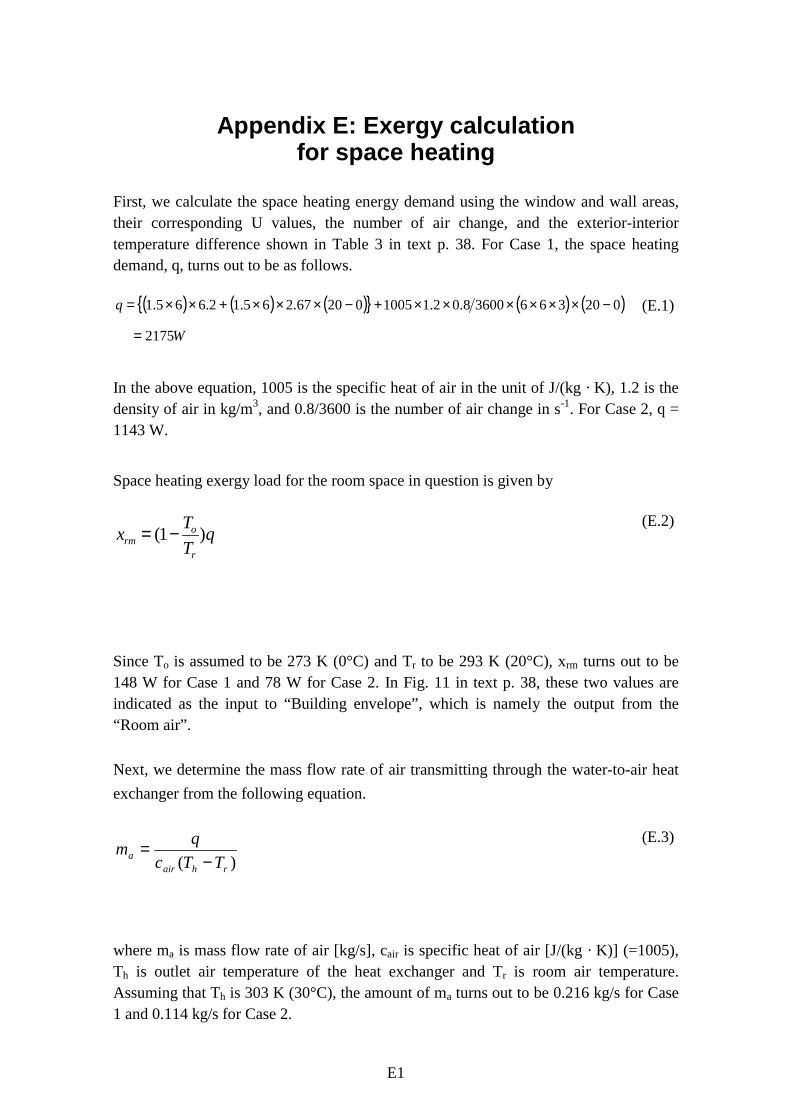
First, we calculate the space heating energy demand using the window and wall areas,their corresponding U values, the number of air change, and the exterior-interiortemperature difference shown in Table 3 in text p. 38. For Case 1, the space heatingdemand, q, turns out to be as follows.
( ) ( ) ( ){ } ( ) ( )W
q
2175
02036636008.02.1100502067.265.12.665.1
=
−××××××+−×××+××= (E.1)
In the above equation, 1005 is the specific heat of air in the unit of J/(kg · K), 1.2 is thedensity of air in kg/m3, and 0.8/3600 is the number of air change in s-1. For Case 2, q =1143 W.
Space heating exergy load for the room space in question is given by
qTTx
r
orm )1( −=
(E.2)
Since To is assumed to be 273 K (0°C) and Tr to be 293 K (20°C), xrm turns out to be148 W for Case 1 and 78 W for Case 2. In Fig. 11 in text p. 38, these two values areindicated as the input to “Building envelope”, which is namely the output from the“Room air”.
Next, we determine the mass flow rate of air transmitting through the water-to-air heatexchanger from the following equation.
)( rhaira TTc
qm−
=(E.3)
where ma is mass flow rate of air [kg/s], cair is specific heat of air [J/(kg · K)] (=1005),Th is outlet air temperature of the heat exchanger and Tr is room air temperature.Assuming that Th is 303 K (30°C), the amount of ma turns out to be 0.216 kg/s for Case1 and 0.114 kg/s for Case 2.
E2
The following step is to calculate the net “warm” exergy delivered by the air circulatedthrough the water-to-air heat exchanger, which is the difference between the “warm”exergies calculated from eq. (A.1) substituting ma for mra, Th for Tr in the case of outletair and Tr for Tr in the case of inlet air. The net “warm” exergy delivered are 182 W forCase 1 and 93 W for Case 2. These two values are the input thermal exergy to “Roomair”.
The fan equipped with the water-to-air heat exchanger delivers these thermal exergies.The exergy requirement of the fan is assumed to be 30 W for Case 1 and 16 W for Case2; this corresponds to a condition that fan efficiency is 0.6 and the pressure decreasebetween the air inlet and outlet of the heat exchanger is about 100 Pa. Then, thechemical exergy to produce the electricity for the fan becomes 81 W (= 30 x 0.94 / 0.35)for Case 1 and 43 W (= 16 x 0.94 / 0.35) for Case 2. Here, the number, 0.94, is the ratioof chemical exergy to the higher heating value of liquefied natural gas (LNG); and thenumber, 0.35, is thermal efficiency of the LNG-fired power plant. The chemical exergyof 81 W or 43 W of chemical exergy required by the fan are comparable to the amountsof space heating exergy load, 148 W or 78 W. This suggests that it is also veryimportant to design a system having as short duct length and low mass flow rate of airas possible.
The next step is to do exergy calculation in terms of water circulation. Here, weassumed the inlet and outlet water temperatures of the water-to-air heat exchanger to be343 K (70°C) and 333 K (60°C), respectively. The mass flow rate of water isdetermined as was done for the air flow rate using eq. (E.3) substituting the specific heatof water, 4186 J/(kg · K), for cair and the inlet water temperature, 343 K (70°C) for Th
and the outlet water temperature, 333 K (60°C) for Tr. The values of mass flow rateobtained are 0.0519 kg/s for Case 1 and 0.0273 kg/s for Case 2. Then the warm exergycontained by water can be calculated from eq. (A.1) substituting 4.186 kJ/(kg · K) forcair, the mass flow rate of water for mra, and the inlet water temperature of 343 K for Tr
in case of inlet water and the outlet water temperature of 333 K for Tr in case of outletwater. The net “warm” exergy delivered by water circulation is the difference in thermalexergy contained by water between the inlet and the outlet; it becomes 419 W for Case1 and 219 W for Case 2. In Fig. 11, these are indicated as the input exergy to “Heatexchanger”.
A pump circulates the water as a working fluid to deliver thermal exergy from the boilerto the water-to-air heat exchanger. The exergy requirement for the pump is assumed tobe 23 W for Case 1 and 12 W for Case 2; this corresponds to a condition that pumpefficiency is 0.7 and the pressure decrease within the pipe is about 300 kPa. Then, thechemical exergy to produce the electricity for the pump becomes 62 W (= 23 x 0.94 /0.35) for Case 1 and 32 W (= 12 x 0.94 / 0.35) for Case 2. The chemical exergy for thepump is smaller than that for the fan, but it is still comparative to the space heating
E3
exergy load especially of Case 2. It is also important to design a system having as shortpipe length and low mass flow rate of water as possible.
The chemical exergy supplied to the boiler is determined by the following equation.
bLNG
qxηα=
(E.4)
where α is the ratio of chemical exergy to the higher heating value of LNG (= 0.94), andηb is the thermal efficiency of the boiler (= 0.8). The value of xLNG turns out to be 2554W for Case 1 and 1342 W for Case 2. In Fig. 11, these are indicated as the input exergyto “Boiler”, respectively. If the boiler efficiency is improved from 0.8 to 0.95, xLNG
turns out to be 2151 W for Case 1; this is indicated, in Fig. 11, as the starting point ofthe dashed line below the solid line of Case 1. The value of xLNG with the boilerefficiency of 0.95 together with the improved thermal insulation of building envelopebecomes 1130 W; this is indicated as the exergy input to the boiler for Case 3.
The detailed excel files for the different cases are shown in Figures E1–E4 with theinput data and the results obtained to generate Fig. 11.
E4
Room Length Width Heigth Volume
m m m m3
6.00 6.00 3.00 108.00
Window Length Heigth Area
m m m2
6.00 1.50 9.00
Exterior Wall Length Heigth Area
m m m2
6.00 1.50 9.00
Air Conditions
Room temperature oC 20.00
Ouside air temperature oCDesign ∆T oC 20.00
Q-Factor 0.0682
Specific heat of air J/(kg K) 1,005.00
Density of air kg/m3 1.20
MiscellaneousPower plant ηplant 0.35
Energy source τNLG 0.94
Specific heat of liquid water J/(kg K) 4,186.00
Case Assessed
U-Window W/(m2 K) 6.20
U-Wall W/(m2 K) 2.67
Air infiltration h-1 0.80
Boiler efficiency 0.80
Pump power W 23.00
Fan power W 30.00
Space heating demand W 2,175.48
Space heating exergy W 148.42
Emission System
Water supply temperature Tsupply oC 70.00
Water return temperature Treturn oC 60.00Output Air Transmitting Temperature Tair
output oC 30.00
Mass flowrate of air through emission system kg/s 0.22
Net exergy delivered to room W 182.23
Mass flowrate of water through emission system kg/s 0.0520
Net exergy delivered by water W 418.05
Chemical exergy to produce fan power W 80.57
Chemical exergy to produce pump power W 61.77
Chemical exergy supplied to boiler W 2,556.19
Case 1
Heat Exchanger
Liquified Natural Gas
Conventional Plant
Fig. E1. Exergy calculations for case 1.
E5
Room Length Width Heigth Volume
m m m m3
6.00 6.00 3.00 108.00
Window Length Heigth Area
m m m2
6.00 1.50 9.00
Exterior Wall Length Heigth Area
m m m2
6.00 1.50 9.00
Air Conditions
Room temperature oC 20.00
Ouside air temperature oCDesign ∆T oC 20.00
Q-Factor 0.0682
Specific heat of air J/(kg K) 1,005.00
Density of air kg/m3 1.20
MiscellaneousPower plant ηplant 0.35
Energy source τNLG 0.94
Specific heat of liquid water J/(kg K) 4,186.00
Case Assessed
U-Window W/(m2 K) 6.20
U-Wall W/(m2 K) 2.67
Air infiltration h-1 0.80
Boiler efficiency 0.95
Pump power W 23.00
Fan power W 30.00
Space heating demand W 2,175.48
Space heating exergy W 148.42
Emission System
Water supply temperature Tsupply oC 70.00
Water return temperature Treturn oC 60.00Output Air Transmitting Temperature Tair
output oC 30.00
Mass flowrate of air through emission system kg/s 0.22
Net exergy delivered to room W 182.23
Mass flowrate of water through emission system kg/s 0.0520
Net exergy delivered by water W 418.05
Chemical exergy to produce fan power W 80.57
Chemical exergy to produce pump power W 61.77
Chemical exergy supplied to boiler W 2,152.58
Case 1-b
Heat Exchanger
Liquified Natural Gas
Conventional Plant
Fig. E2. Exergy calculations for case 1b.
E6
Room Length Width Heigth Volume
m m m m3
6.00 6.00 3.00 108.00
Window Length Heigth Area
m m m2
6.00 1.50 9.00
Exterior Wall Length Heigth Area
m m m2
6.00 1.50 9.00
Air Conditions
Room temperature oC 20.00
Ouside air temperature oCDesign ∆T oC 20.00
Q-Factor 0.0682
Specific heat of air J/(kg K) 1,005.00
Density of air kg/m3 1.20
MiscellaneousPower plant ηplant 0.35
Energy source τNLG 0.94
Specific heat of liquid water J/(kg K) 4,186.00
Case Assessed
U-Window W/(m2 K) 3.60
U-Wall W/(m2 K) 1.14
Air infiltration h-1 0.40
Boiler efficiency 0.80
Pump power W 17.00
Fan power W 16.00
Space heating demand W 1,142.64
Space heating exergy W 77.96
Emission System
Water supply temperature Tsupply oC 70.00
Water return temperature Treturn oC 60.00Output Air Transmitting Temperature Tair
output oC 30.00
Mass flowrate of air through emission system kg/s 0.11
Net exergy delivered to room W 95.71
Mass flowrate of water through emission system kg/s 0.0273
Net exergy delivered by water W 219.57
Chemical exergy to produce fan power W 42.97
Chemical exergy to produce pump power W 45.66
Chemical exergy supplied to boiler W 1,342.60
Case 2
Heat Exchanger
Liquified Natural Gas
Conventional Plant
Fig. E3. Exergy calculations for case 2.
E7
Room Length Width Heigth Volume
m m m m3
6.00 6.00 3.00 108.00
Window Length Heigth Area
m m m2
6.00 1.50 9.00
Exterior Wall Length Heigth Area
m m m2
6.00 1.50 9.00
Air Conditions
Room temperature oC 20.00
Ouside air temperature oCDesign ∆T oC 20.00
Q-Factor 0.0682
Specific heat of air J/(kg K) 1,005.00
Density of air kg/m3 1.20
MiscellaneousPower plant ηplant 0.35
Energy source τNLG 0.94
Specific heat of liquid water J/(kg K) 4,186.00
Case Assessed
U-Window W/(m2 K) 3.60
U-Wall W/(m2 K) 1.14
Air infiltration h-1 0.40
Boiler efficiency 0.95
Pump power W 17.00
Fan power W 16.00
Space heating demand W 1,142.64
Space heating exergy W 77.96
Emission System
Water supply temperature Tsupply oC 70.00
Water return temperature Treturn oC 60.00Output Air Transmitting Temperature Tair
output oC 30.00
Mass flowrate of air through emission system kg/s 0.11
Net exergy delivered to room W 95.71
Mass flowrate of water through emission system kg/s 0.0273
Series title, number andreport code of publication
VTT Research Notes 2158VTT–TIED–2158
Author(s)Shukuya, Masanori & Hammache, Abdelaziz
TitleIntroduction to the Concept of Exergy – for a Better Understandingof Low-Temperature-Heating and High-Temperature-CoolingSystems
AbstractChapter I describes the characteristics of a thermodynamic concept, exergy, in association withbuilding heating and cooling systems. Exergy is the concept that explicitly indicates ‘what isconsumed’. All systems, not only engineering systems but also biological systems including thehuman body, work feeding on exergy, consuming its portion and thereby generating thecorresponding entropy and disposing of the generated entropy into their environment. The wholeprocess is called ‘exergy-entropy process’. The features of ‘warm’ exergy and ‘cool’ exergy andalso radiant exergy are outlined. General characteristics of exergy-entropy process of passivesystems, which would be a prerequisite to realize low exergy systems, are discussed togetherwith the exergy-entropy process of the global environmental system.Chapter II introduces the various forms of exergy and the mathematical formulations used toevaluate them. The exergy balance on an open steady state system, which is much more relevantto thermodynamic analysis of energy systems, is also described, as well as the different exergeticefficiency factors introduced in the thermodynamic analysis of energy systems. Next, an exergyanalysis example is outlined through an air-conditioning application. Air-conditioningapplications are widely used in heating and cooling of buildings.Chapter III introduces an example of exergy calculation for space heating systems. The issues tohave a better understanding of low-exergy systems for heating and cooling are raised. It issuggested that a prerequisite for low exergy systems would be rational passive design of buildingenvelope systems.
Activity unitVTT Building and Transport, Lämpömiehenkuja 3, P.O.Box 1804, FIN–02044 VTT, Finland
ISBN Project number951–38–6074–4 (soft back ed.)951–38–6075–2 (URL: http://www.inf.vtt.fi/pdf/)
Date Language Pages PriceSeptember 2002 English 41 p. + app. 17 p. B
Name of project Commissioned byEnergy Conservation in Buildings and CommunitySystems Programme ECBCS, ”Annex 37: Low ExergySystems for Heating and Cooling”
VTT Building and Transport
Series title and ISSN Sold byVTT Tiedotteita – Research Notes1235–0605 (soft back edition)1455–0865 (URL: http://www.inf.vtt.fi/pdf/)
ISBN 951–38–6074–4 (soft back ed.) ISBN 951–38–6075–2 (URL: http://www.inf.vtt.fi/pdf/)ISSN 1235–0605 (soft back ed.) ISSN 1455–0865 (URL: http://www.inf.vtt.fi/pdf/)
ESPOO 2002 VTT RESEARCH NOTES 2158
Masanori Shukuya & Abdelaziz Hammache
Introduction to the Concept of Exergy -for a Better Understanding of Low-Temperature-Heatingand High-Temperature-Cooling Systems
Submitted to IEA ANNEX37“Low Exergy Systems for Heating and Cooling of Buildings”
VTT TIEDOTTEITA – RESEARCH NOTES
VTT RAKENNUS- JA YHDYSKUNTATEKNIIKKA – VTT BYGG OCHTRANSPORT – VTT BUILDING AND TRANSPORT
2116 Ryynänen, Tiia, Kallonen, Raija & Ahonen, Eino. Palosuojatut tekstiilit. Ominaisuudetja käyttö. 2001. 101 s.
2118 Kärki, Otto. Alkolukko rattijuopumuksen ehkäisyssä. Esiselvitys. 2001. 85 s. + liitt. 3 s.
2119 Tillander, Kati & Keski-Rahkonen, Olavi. Rakennusten syttymistaajuudet PRONTO-tietokannasta 1996–1999. 2001. 66 s. + liitt. 16 s.
2120 Koota, Jaana. Construction site safety. Case United States. 2001. 39 p. + app. 3 p.
2121 Tervonen, Juha & Räsänen, Jukka. Environmental assessment of strategic transport ac-tions. SEA in CODE-TEN. 2001. 25 p. + app. 7 p.
2123 Hietaniemi, Jukka, Baroudi, Djebar, Korhonen, Timo, Björkman, Jouni, Kokkala, Matti& Lappi, Esa. Yksikerroksisen teollisuushallin rakenteiden palonkestävyyden vaikutuspaloturvallisuuteen. Riskianalyysi ajasta riippuvaa tapahtumapuumallia käyttäen. 2002.95 s. + liitt. 51 s.
2124 Talja, Asko, Toratti, Tomi & Järvinen, Erkki. Lattioiden värähtelyt. Suunnittelu ja ko-keellinen arviointi. 2002. 51 s. + liitt. 13 s.
2125 Riihimäki, Markku & Siekkinen, Heidi. Asiakastarpeet kiinteistöliiketoiminnassa. Liike-ja toimistokiinteistöt. 2002. 74 s. + liitt. 10 s.
2126 Kauppinen, Anna-Kaisa, Pietilä, Paula, Sundbäck, Liisa & Kaleva, Hanna. Kiinteistöjoh-tamisen tehostaminen – vaihtoehtona ulkoistaminen. Ulkoistamisen edellytykset ja pää-töksenteon mallintaminen. 2002. 73 s. + liitt. 4 s.
2128 Hietaniemi, Jukka, Hakkarainen, Tuula, Huhta, Jaakko, Korhonen, Timo, Siiskonen,Jaakko & Vaari, Jukka. Ontelotilojen paloturvallisuus. Ontelopalojen tutkimus kokeelli-sesti ja mallintamalla. 2002. 125 s. + liitt. 63 s.
2134 Paiho, Satu, Karjalainen, Sami, Alanne, Kari, Norvasuo, Markku, Eriksson, Lasse, Pöy-hönen, Sanna, Kaartinen, Jani & Lehtovaara, Jorma. Rakennusten uudet säätö- ja ener-gianhallintaratkaisut. 2002. 279 s. + liitt. 9 s.
2136 Hietaniemi Jukka & Baroudi, Djebar. Physical Interpretation of Temperature Data Me-asured in the SBI Fire Test. Nordtest Technical Report 416. Nordtest Project No. 1381-98. 2002. 47 p. + app. 4 p.
2144 Saari, Mikko, Pallari, Marja-Liisa, Salonvaara, Mikael, Kääriäinen, Hannu, Viitanen,Hannu, Humala, Iris, Liski-Markkanen, Sari, Malin, Anne & Laitinen, Kirsi. Terveensaunan tekijät. 2002. 60 s. + liitt. 47 s.
2147 Ritola, Jouko & Vuopio, Jaakko. Kalliotilojen vesitiiviyden hallinta. 2002. 124 s.
2154 Vainio, Terttu, Jaakkonen, Liisa, Nippala, Eero, Lehtinen, Erkki & Isaksson, Kaj. Kor-jausrakentaminen 2000–2010. 2002. 60 s. + liitt. 25 s.
2158 Shukuya, Masanori & Hammache, Abdelaziz. Introduction to the Concept of Exergy -for a Better Understanding of Low-Temperature-Heating and High-Temperature-CoolingSystems. 2002. 14 p. + app. 17 p.