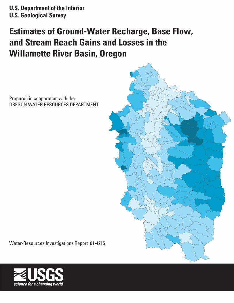
U.S. Department of the Interior U.S. Geological Survey Estimates of Ground-Water Recharge, Base Flow, and Stream Reach Gains and Losses in the Willamette River Basin, Oregon By KARL K. LEE AND JOHN C. RISLEY Water-Resources Investigations Report 01–4215 Prepared in cooperation with the OREGON WATER RESOURCES DEPARTMENT Portland, Oregon: 2002
Transcript
U.S. Department of the InteriorU.S. Geological Survey
Estimates of Ground-Water Recharge, Base Flow, and Stream Reach Gains and Losses in the Willamette River Basin, Oregon
By KARL K. LEE AND JOHN C. RISLEY
Water-Resources Investigations Report 01–4215
Prepared in cooperation with theOREGON WATER RESOURCES DEPARTMENT
Portland, Oregon: 2002
U.S. DEPARTMENT OF THE INTERIORGALE A. NORTON, Secretary
U.S. GEOLOGICAL SURVEYCHARLES G. GROAT, Director
The use of trade, product, or firm names in this publication is fordescriptive purposes only and does not imply endorsement by theU.S. Government.
For additional information contact: Copies of this report can bepurchased from:
District ChiefU.S. Geological Survey USGS Information Services10615 S.E. Cherry Blossom Drive Box 25286, Federal CenterPortland, OR 97216-3159 Denver, CO 80225-0046E-mail: [email protected] Telephone: 1-888-ASK-USGSInternet: http://oregon.usgs.gov
Suggested citation:
Lee, K.K., and Risley, J.C., 2002, Estimates of ground-water recharge, base flow, and stream reach gains and losses in the Willamette River Basin, Oregon: U.S. Geological Survey Water-Resources Investigations Report 01–4215, 52 p.
Purpose and Scope ............................................................................................................................................2Approach ...........................................................................................................................................................2Study Area Description .....................................................................................................................................2Acknowledgments.............................................................................................................................................4
Model Description.................................................................................................................................5Model Modifications.............................................................................................................................6
Hydrologic Response Unit Recharge ........................................................................................6Irrigation ....................................................................................................................................7
Delineation of Basin Physical Characteristics ......................................................................................8Land Use....................................................................................................................................8Slope and Aspect .......................................................................................................................9Soils ...........................................................................................................................................9Surficial Geology.......................................................................................................................9
Model Parameterization ........................................................................................................................9Hydrologic Response Unit-Related Parameters 9Basinwide Parameters .............................................................................................................10
Time-Series Input Data .......................................................................................................................11Precipitation.............................................................................................................................11Air Temperature ......................................................................................................................11
Recharge and Base-Flow Estimates from Streamflow Records......................................................................16Recharge Estimates .............................................................................................................................16Base-Flow Estimates...........................................................................................................................16
Accuracy 20Stream Gain-Loss Field Investigations 20Ground-Water Recharge Estimates .................................................................................................................23
Recharge Estimates From Precipitation-Runoff Model......................................................................23Results ........................................................................................................................................................................23
Recharge Estimates from Daily Streamflow Records 26Recharge Estimates from Willamette Lowland Regional Aquifer-System Analysis 26Comparison of Recharge Estimates ....................................................................................................29
Stream Reach Gain/Loss Estimates.................................................................................................................30Middle Fork and Main-Stem Willamette River ..................................................................................31South Yamhill River ...........................................................................................................................33Pudding River .....................................................................................................................................33South Santiam River ...........................................................................................................................35
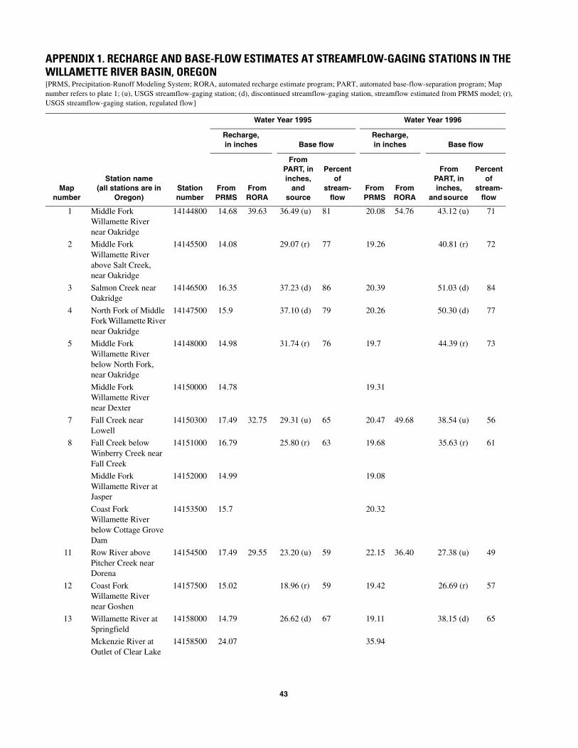
Summary and Conclusions.........................................................................................................................................36Selected References ...................................................................................................................................................38Appendix 1. Recharge and base-flow estimates at streamflow-gaging-station locations in the
Willamette River Basin..........................................................................................................................43
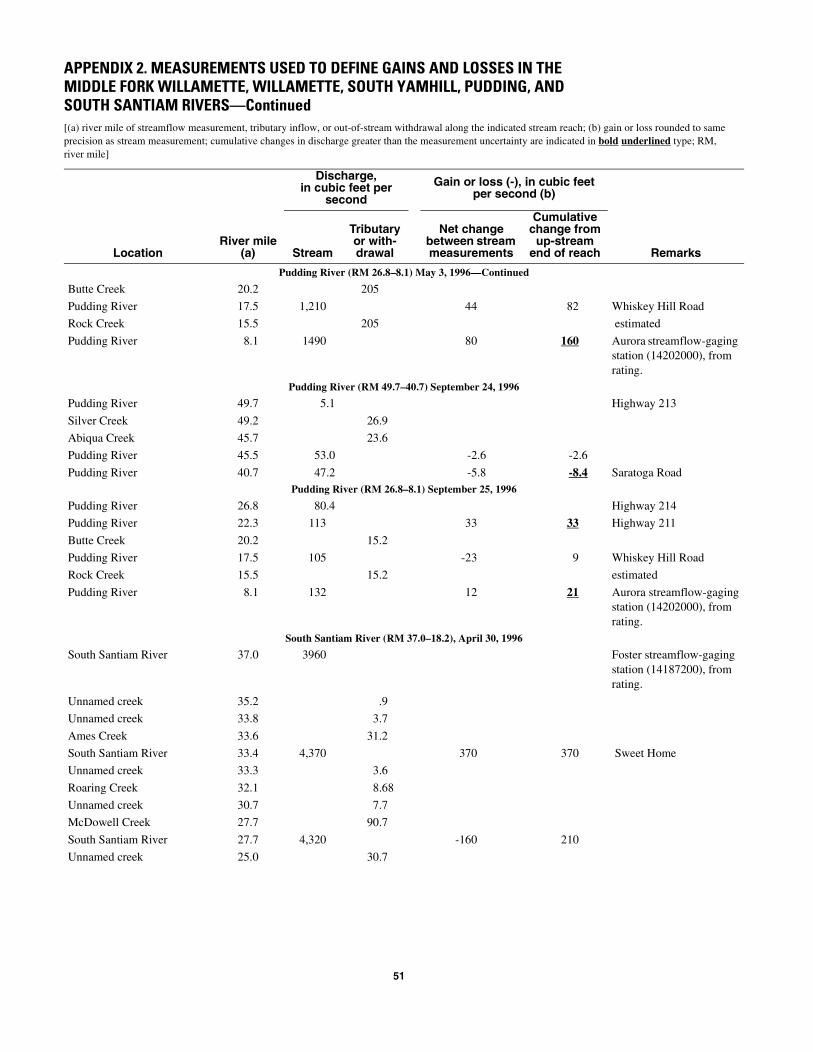
Appendix 2. Measurements used to define gains and losses in the Middle Fork Willamette, Willamette, South Yamhill, Pudding, and South Santiam Rivers .............................................................................47
PLATE
1. Map showing base flow as a percentage of total streamflow at selected sites in the Willamette River Basin, Oregon, water years 1995 and 1966–96.
TABLES
Table 1. Weekly irrigation application rates used in the Precipitation-RunoffModeling for the Willamette River Basin, Oregon ...................................................................................7
Table 2. Hydrologic soil groups used in the study ...................................................................................................9Table 3. Geologic assemblages grouped according to water-bearing characteristics ............................................10Table 4. Basin spatial-coverage categories and corresponding code numbers ......................................................11Table 5. Climate stations used to collect data for input to precipitation-runoff models of the
Willamette River Basin, Oregon ..............................................................................................................13Table 6. Comparison of observed and simulated 1995 water year runoff for nine unregulated small
subbasins in the Willamette River Basin, Oregon....................................................................................16Table 7. Comparison of observed and simulated mean annual flow at selected sites in the
Willamette River Basin, Oregon ..............................................................................................................19Table 8. Estimates of mean annual recharge on the basis of mean annual precipitation, generalized surficial
geology, and land-use and land-cover categories from the Willamette Lowland Regional Aquifer System Analysis .........................................................................................................28
FIGURES
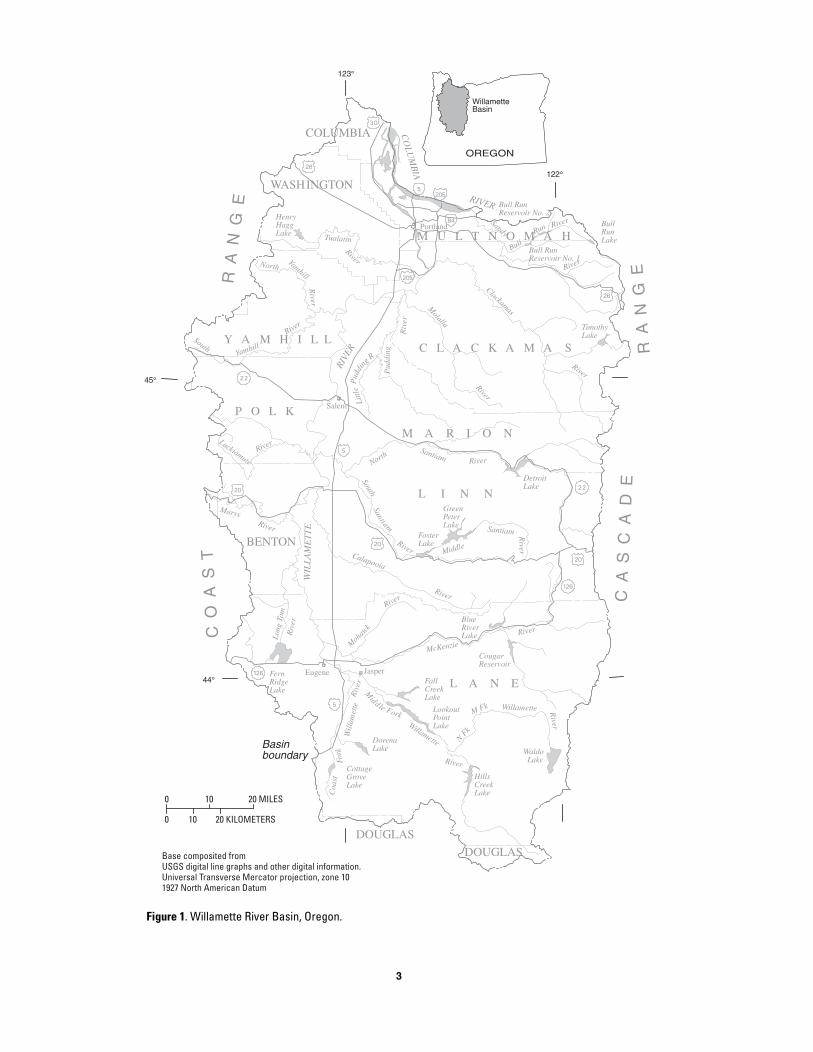
Figure 1. Map showing Willamette River Basin, Oregon..........................................................................................3Figure 2. Flow diagram of the Precipitation-Runoff Modeling System conceptual model ...................................... 5Figure 3. Map showing major subbasins of the Willamette River Basin, Oregon.....................................................8Figure 4. Map showing mean annual precipitation in the Willamette River Basin, Oregon, 1961–90 ...................12Figure 5. Map showing location of climatological stations in the Willamette River Basin, Oregon,
at which data used in this study were collected ........................................................................................15Figure 6. Graph showing observed and simulated 1995 daily mean flow for station 14187000 on
Wiley Creek near Foster, Oregon .............................................................................................................17Figure 7. Map showing difference in mean annual observed and simulated flow at selected gages
throughout the Willamette River Basin, Oregon, 1973–96 ......................................................................18Figure 8. Graphs showing annual mean observed and simulated discharge for three sites in the Willamette River
Basin, Oregon ...........................................................................................................................................21Figure 9. Graph showing relation of annual mean streamflow to estimated annual mean base flow at
Calapooia River at Holley, Oregon (14172000), for water years 1936–90..............................................22Figure 10. Map showing model simulation results for hydrologic parameters in the Willamette River Basin,
Oregon, 1973–96 ......................................................................................................................................24Figure 11. Maps showingcmparison of Precipitation-Runoff Modeling System simulated mean annual
recharge and Willamette Lowland Aquifer estimated mean annual recharge ..........................................27Figure 12. Graph showing observed and simulated streamflow, base flow estimated from base-flow separation, |
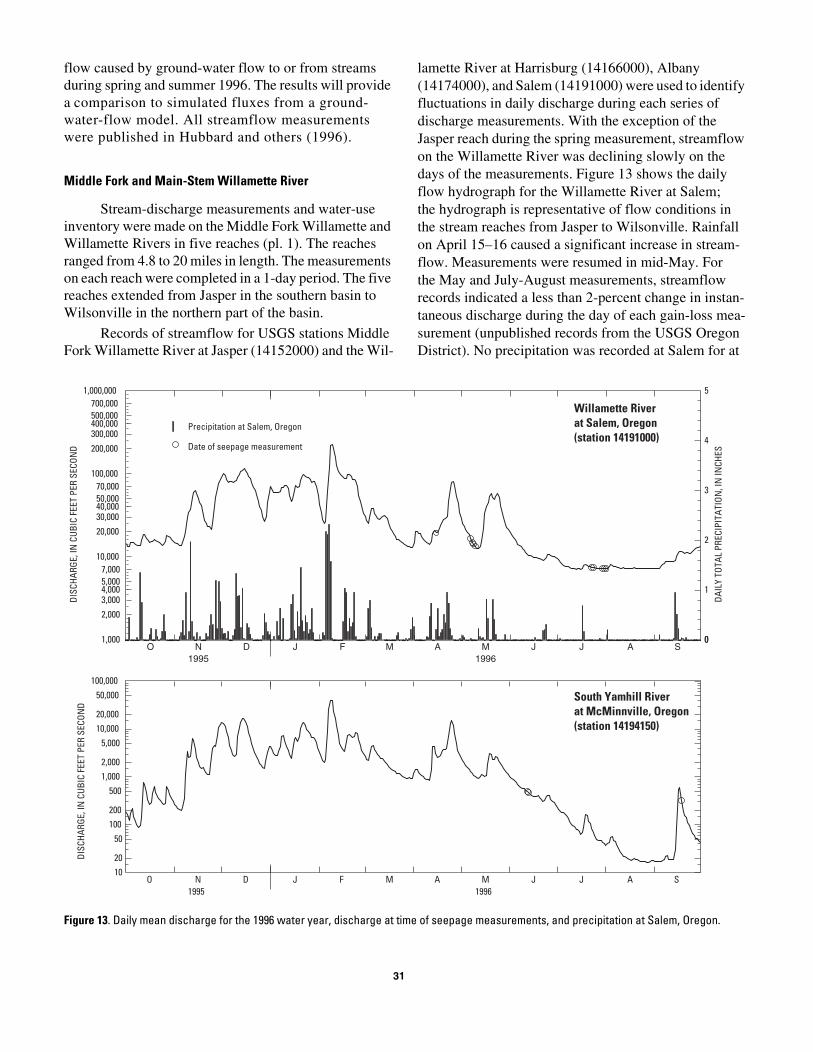
and base flow estimated from PRMS on the Calapooia River at Holley, Oregon (14172000) ............... 30Figure 13. Graph showing daily mean discharge for the 1996 water year, discharge at time
of seepage measurements, and precipitation at Salem, Oregon................................................................31Figure 14. Graph showing ains to and losses from selected reaches of the Middle Fork Willamette River
from Jasper to Springfield and the Willamette River from Eugene to Wilsonville, Oregon, for the periods April–May and July–August 1996 ...................................................................................32
Figure 15. Graph showing gains to and losses from selected reaches of the South Yamhill River from
Sheridan to McMinnville, Oregon, for June and September 1996 ...........................................................33Figure 16. Graph showing daily mean discharge for water year 1996, discharge at time of seepage
measurement, and precipitation at Salem, Oregon ...................................................................................34Figure 17. Graph showing gains to and losses from selected reaches of the Pudding River
from Silverton to Aurora, Oregon, for May and September 1996............................................................35Figure 18. Graph showing gains to and losses from the South Santiam River from Foster to Lebanon,
Oregon, for April and September 1996 ....................................................................................................36
CONVERSION FACTORS
Multiply By To obtain
cubic foot per second (ft3/s) 0.02832 cubic meter per second (m3/s)inch 25.4 millimeter (mm)foot (ft) 0.3048 meter (m)mile (mi) 1.609 kilometer (km)square mile (mi2) 2.590 square kilometer (km2)
Temperature in degrees Celsius (°C) as follows:°C = (°F-32)/1.8.
Sea level: In this report “sea level” refers to the National Geodetic Vertical Datum of 1929 (NGVD of 1929)—a geodetic datum derived from a general adjustment of the first-order level nets of both the United States and Canada, called Mean Sea Level of 1929.
1
Estimates of Ground-Water Recharge, Base Flow, and Stream-Reach Gains and Losses in the Willamette River Basin, Oregon
By Karl K. Lee and John C. Risley
Abstract
Precipitation-runoff models, base-flow-separation techniques, and stream gain-loss measurements were used to study recharge and ground-water surface-water interaction as part of a study of the ground-water resources of the Willamette River Basin. The study was a cooperative effort between the U.S. Geological Survey (USGS) and the State of Oregon Water Resources Department (OWRD). Precipitation-runoff models were used to estimate the water budget of 216 subbasins in the Willamette River Basin. The models were also used to compute long-term average recharge and base flow. Recharge and base-flow estimates will be used as input to a regional ground-water flow model, within the same study. Recharge and base-flow estimates were made using daily streamflow records. Recharge estimates were made at 16 streamflow-gaging-station locations and were compared to recharge estimates from the precipitation-runoff models. Base-flow separation methods were used to identify the base-flow component of streamflow at 52 currently operated and discontinued stream-flow-gaging-station locations. Stream gain-loss measurements were made on the Middle Fork Willamette, Willamette, South Yamhill, Pudding, and South Santiam Rivers, and were used to identify and quantify gaining and losing stream reaches both spatially and temporally. These
1
measurements provide further understanding of ground-water/surface-water interactions.
INTRODUCTION
Approximately 70 percent of the population of Oregon lives in the Willamette River Basin. The grow-ing population and economy of the basin is increasing the demand for water for urban, industrial, and agricul-tural uses. Although western Oregon is known for its abundant precipitation, most of it falls from October through May. Summer precipitation is insufficient to meet water demands. Because of this, many streamsin the Willamette River Basin are closed to additional out-of-stream appropriations in the summer. Therefore, ground water is the main resource available to satisfy the growing water demand. An evaluation of the impact of this demand requires a quantitative understanding of the water budget of the basin, including an evaluation of the potential impacts of ground-water pumpage on streamflow. In 1995, the U.S. Geological Survey (USGS) began a cooperative study with the Oregon Water Resources Department (OWRD) to better under-stand the ground-water hydrology of the region. The principal means to accomplish this goal is to develop and calibrate a numerical ground-water flow model. This ground-water-flow model will serve as a tool to help understand declining ground-water levels, the effect of ground-water withdrawals on ground-water levels and streamflow, and assess the effects of possible management scenarios.
The cooperative study seeks to address three major ground-water management issues in the Wil-lamette River Basin identified by the OWRD (1992):
(1) understanding ground-water/surface-water connec-tions, (2) controlling long-term ground-water-level declines, and (3) identifying spatial distribution of arsenic concentrations in ground water of the Wil-lamette River Basin.
The study has generated three reports prior to this one. Ground-water data collected and compiled for this regional ground-water study are available in printed and digital form (Orzol and others, 2000). O’Connor and others (2001) documented the extent, thickness, and description of coarse-grained alluvial deposits underly-ing and adjacent to the Willamette River and its major tributaries, which are important to understand the inter-action between surface and ground water. Hinkle and Polette (1999) discussed the distribution of naturally occurring arsenic in ground water.
Purpose and Scope
This report estimates annual recharge to the ground-water system of the Willamette Valley and eval-uates the exchange of water between streams and the ground-water system. This information is needed to quantitatively understand the ground-water system and to coordinate the management of ground- and surface-water resources. Recharge estimates will be used as input to a regional ground-water flow model. Estimates of base flow and stream gains and losses will be used as calibration targets for the flow model.
Approach
Multiple methods of study were used for both recharge estimates and to quantify ground-water exchange with streamflow. Both recharge and the exchange of water between streams and aquifers are key components in the development and calibration of ground-water flow models. These parameters, however, are often difficult to measure or estimate with a high level of certainty. For this study, a variety of techniques were used to help identify the uncertainty and to assess the strengths and weaknesses of different approaches for determining these parameters in the study area.
Recharge was estimated using two methods. A precipitation-runoff model was used to develop a water budget, of which recharge was one component. The input to the model is precipitation and air-temperature data. The precipitation-runoff model uses mathematical equations to simulate physical processes such as snow-
2
melt, evapotranspiration, and infiltration. Model output includes surface runoff, recharge to the ground-water system, and ground-water discharge to streams through-out the study area. The model is calibrated using mea-sured streamflow data. In another method, recharge was estimated at selected streamflow-gaging-station loca-tions using daily streamflow data. This method describes streamflow recession during times when all flow can be considered to be ground-water discharge and estimates recharge for each peak in the streamflow record.
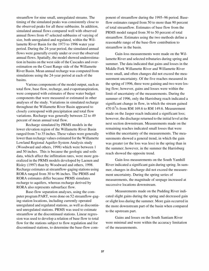
Annual mean base flow was estimated using two methods. First, estimates of recharge made by the pre-cipitation-runoff model were assumed to be equal to base flow. Second, base flow was estimated at selected streamflow-gaging-station locations using hydrograph separation, which differentiates the surface-runoff com-ponent from the ground-water discharge component of streamflow.
Measurements of streamflow were made to iden-tify gaining or losing stream reaches. These gains or losses in streamflow may be attributed to ground-water flow to or from the stream. Results were compared to previous gain/loss studies in the Willamette River Basin.
Study Area Description
The Willamette River Basin (fig. 1) has an area of approximately 12,000 mi2 (square miles) and contains the State’s four largest cities, Portland, Eugene, Salem, and Gresham. Approximately 2 million people, 70 per-cent of the total population of the State, live in the basin (U.S. Census Bureau, 2000). The basin supports an economy based on agriculture, manufacturing, timber, and recreation and contains extensive fish and wildlife habitat.
The Willamette River Basin has a temperate marine climate characterized by dry summers and wet winters. About 80 percent of annual precipitation falls between October and May, resulting in dry conditions during the summer, when demand for water is high. Mean annual precipitation ranges from about 40 inches in the lowlands to 175 inches at the crests of the Coast and Cascade Ranges. About 35 percent of the precipita-tion at and above 4,000 foot elevation falls as snow, and more than 75 percent falls at and above 7,000 feet as snow. Because the basin is largely dominated by marine air, both annual and diurnal temperature
Figure 1. Willamette River Basin, Oregon.
Base composited fromUSGS digital line graphs and other digital information.Universal Transverse Mercator projection, zone 101927 North American Datum
Pud
ding
R
N Fk
M Fk Willamette River
Moh
awk
Marys
Middle
Santiam
NorthSantiam River
Littl
e
Pud
ding
Riv
er
South
River
North
River
Clackamas
BullRun River
RiverM
olalla
Calapooia
River
River
River
Sandy
River
River
River
River
McKenzie
River
Midd le Fork
Willamette
Riv
er
Coa
stFo
rk
Tualatin
River
Santiam
South
River
YamhillW
illam
ette
CO
LUM
BIA
RIVER
WIL
LAM
ETT
E
RIVE
R
Yamhill
River
Long
Tom
Riv
er
Luckiamute
Waldo Lake
HillsCreekLake
LookoutPointLake
FallCreekLake
DorenaLake
CottageGroveLake
BlueRiverLake
CougarReservoir
FosterLake
GreenPeterLake
DetroitLake
TimothyLake
HenryHaggLake
FernRidgeLake
Bull RunReservoir No. 1
Bull RunReservoir No. 2
BullRunLakeM U L T N O M A H
COLUMBIA
WASHINGTON
C L A C K A M A S
P O L K
BENTON
L I N N
M A R I O N
L A N E
DOUGLAS
Y A M H I L L
DOUGLAS
Eugene Jasper
Portland
Salem
R A
N G
E
C O
A S
T
R A
N G
EC
A S
C A
D E
Basinboundary
44
45
122
123
20 MILES
10
10
20 KILOMETERS0
0
OREGON
WillametteBasin
3
ranges are relatively small. In the basin, the average annual temperature ranges between 40 degrees Fahrenheit (oF) to 65oF, and is primarily dependent on elevation. The average daily minimum is 30oF in January and the average daily maximum tempera-ture is 80oF in July at lower elevations in the valley.
Most of the flow in the Willamette River occurs from November to March as a result of persistent winter rainstorms and spring snowmelt. Snowmelt supplies about 35 percent of the annual flow, either directly to the stream or indirectly through the ground-water sys-tem (Laenen and Risley, 1997).
The basin is bounded on the west by the Coast Range, on the east by the Cascade Range, on the south by the Calapooya Divide, and on the north by the Columbia River. Elevations range from less than 10 feet above sea level near the Columbia River to about 4,000 feet in the Coast Range and the Calapooya Divide, to more than 10,000 feet in the Cascade Range. About 20 percent of the basin is above 4,000 feet, which is con-sidered the lower limit of the transient snow zone. On the basis of physiography (Fenneman, 1931) and geol-ogy (Baldwin, 1981), the Willamette River Basin can be divided into three north-south-trending provinces: the Cascade Range, the Coast Range, and the Willamette River Valley.
The slopes and foothills of the Cascade Range account for more than 50 percent of the basin area. The Cascade Range is composed of volcanic rocks consist-ing of (1) Tertiary basaltic and andesitic rocks with associated volcanic debris, primarily in the western part of the range, and (2) Quaternary basaltic and andesitic lava flows, primarily in the High Cascade Range.
The slopes and foothills of the Coast Range make up about 20 percent of the basin area. The Coast Range is composed of Tertiary marine sandstone, shale, and mudstone interbedded with volcanic basalt flows and volcanic debris.
The Willamette River Valley, generally consid-ered the part of the basin below 500 feet, is about 30 mi wide and 117 mi long and represents about 30 percent of the basin area. Much of the terrain in the Willamette River Valley up to an elevation of about 400 feet is cov-ered by sandy to silty terrace deposits that border exist-ing rivers and form alluvial fans near river mouths. These deposits were derived from the surrounding mountains, and they consist of intermingling layers of clay, silt, sand, and gravel.
At the surface, the lowlands of the Willamette River valley are covered mostly by fine-grained depos-
4
its (silt to fine sand), except in the Portland area, Canby, and the flood plain of some of the major streams where coarse-grained deposits occur. Coarse-grained material underlies the fine-grained deposits, and in some areas these deposits are hundreds of feet thick, such as in bur-ied alluvial fans along the east side of the valley. With the exception of the Willamette, Santiam, and McKen-zie Rivers, most rivers flow over the fine-grained mate-rial.
The main stem of the Willamette River is formed by the confluence of the Coast and Middle Forks near Eugene and flows 187 mi to the Columbia River. The main stem can be divided into four distinct reaches whose physical characteristics govern the hydraulics of flow. The upper reach extends from Eugene to Albany, river mile (RM) 187 to 119, and is characterized by a meandering and braided channel with many islands and sloughs. The river is shallow and the bed is composed almost entirely of cobbles and gravel which, during the summer, are covered with biological growth. The mid-dle reach extends from Albany to the mouth of the Yam-hill River, RM 119 to 55, and is characterized by a meandering channel deeply incised into the valley. The Newberg Pool reach extends from RM 55 to Willamette Falls at RM 26.5. Hydraulically, the deep, slow-moving pool can be characterized as a reservoir. The pool is a depositional area for small gravel-to silt-sized material. The Newberg Pool terminates at Willamette Falls, a 50-foot high natural falls, with flashboards used to control pool elevation during the summer. The tidal reach, which is downstream of Willamette Falls, is controlled by backwater from the Columbia River.
Acknowledgments
The authors wish to acknowledge the help of Ken Skach of the U.S. Geological Survey in Portland, Ore-gon, for GIS assistance and for writing script programs that processed data and model output files. We would also like to thank George Taylor, Oregon State Clima-tologist, for providing climatological data.
METHODS
The following sections describe the methods used to estimate recharge to the aquifer, base flow, and streamflow gain and losses in selected stream reaches. These methods include precipitation-runoff models,
recharge and base-flow estimates from daily stream-flow records, and gain-loss measurements.
Precipitation-Runoff Modeling
Precipitation-runoff modeling was used in the study to provide an approximation of the water budget and to provide inputs for a ground-water model of the study area.
Model Description
Precipitation-runoff models for the Willamette River Basin were developed in an earlier USGS study with the Oregon Department of Environmental Quality (ODEQ) (Laenen and Risley, 1997). These models, based on the Precipitation-Runoff Modeling System (PRMS) program (Leavesley and others, 1983), were constructed to estimate ungaged tributary inflows for stream-channel routing models. The routing models were used with a solute-transport model to calculate water-quality constituent loads. The models constructed in that study encompassed regions adjacent to the main stem of the Willamette River and the lower regions of the major tributaries. For this study, the precipitation-runoff models were expanded to a total of 216 small subbasins. Additionally, revised and more detailed land-surface data were used to refine the models.
The PRMS model is designed to analyze the effects of precipitation, climate, and land-use on streamflow within the confines of a drainage basin. The model uses mathematical equations to simulate physical processes such as precipitation, snowmelt, evaporation, evapotranspiration, interception, and infiltration. Land surface heterogeneity is accounted for by partitioning the basin into areas based on user-defined criteria such as elevation, slope, aspect, land use, soil type, geology, and precipitation. Areas with similar properties are assumed to respond in a hydrologically similar manner and are designated as a hydrologic-response unit (HRU). The user determines the size, shape, and num-ber of HRUs that will be used in a basin model. A PRMS basin model can be assigned any number of HRUs. For the 216 subbasins modeled in this study, thousands of HRUs were delineated.
In PRMS, the basin hydrologic cycle is conceptu-alized as a series of reservoirs (fig. 2). The model com-putes the movement of water and/or energy between the reservoirs for each time step during the simulation.
5
Figure 2. Flow diagram of the Precipitation-Runoff Modeling System conceptual model (Leavesley and others, 1983).
Each PRMS basin model is self-contained. Water does not flow laterally from one basin model to another. Sys-tem inputs of precipitation and air temperature (or pan evaporation) drive the processes of evaporation, tran-spiration, snowfall and snowmelt, and sublimation. In this study, PRMS was operated in the daily mode. Streamflow at the outlet of a basin model is the sum of the various reservoir contributions, which are summed from the HRUs in the basin. In addition to flow at the basin outlet, model output includes all reservoir storage levels and all flows between the reservoirs.
During each time step, precipitation can fall on impervious surfaces, pervious surfaces, or snowpack. The entire surface area of each HRU is characterized as impervious or pervious by the user. Snowpack condi-tions can occur on either impervious or pervious sur-
Interception
Snowpack
Impervious-zonereservoir
Soil-zonereservoir
Recharge zone
Lower zone
Subsurfacereservoir
Ground-waterreservoir
Airtemperature Precipitation
INPUTS
Eva
po
tra
nsp
ira
tio
n
Evaporation
Throughfall
Snowmelt
Evaporation
Sublimation
Sublimation
Evaporation
Transpiration
Transpiration
Surface
runoff
Surface runoff
Subsurface
Flow
Ground-water flow
Ground-water recharge
Subsurface
rechargeGround-water
recharge
Soil-zone excess
Str
ea
mfl
ow
faces when the climate time-series input data exceeds various user defined thresholds in the model parameters.
When the surface is impervious, there is no inter-ception storage or interception losses. Surface retention of water is conceptualized as a storage reservoir. A maximum retention storage capacity for the reservoir must be satisfied before surface flow can occur. When free of snow, the reservoir is depleted by evaporation.
For pervious surfaces, precipitation is reduced by interception in the vegetation and becomes net precipi-tation on the basin surface. Water stored as interception is depleted through evaporation. Water on the surface then enters the soil-zone reservoir as infiltration until the reservoir is filled. Water on the surface in excess of the soil-zone reservoir capacity becomes runoff. The soil-zone reservoir is conceptualized as a two-layered (recharge zone and lower zone) system. Each zone has user-defined depth and water-storage characteristics. Evaporation and transpiration deplete moisture from the recharge zone. However, moisture in the lower zone is depleted only through transpiration. The lower zone depth should reflect the rooting depth of the predomi-nant vegetation type of the HRU. The Hamon method (Hamon, 1961) option within PRMS was used to esti-mate potential evapotranspiration in this study. The method incorporates 12 monthly coefficients that are used in conjunction with minimum and maximum air temperatures. Actual evapotranspiration is computedas a function of the available water in the two soil zone reservoirs.
For daily rainfall on a snow-free, pervious-sur-face HRU, surface flow is computed using the contrib-uting- or variable-source area approach, where a dynamic saturated source area expands and contracts according to rainfall characteristics and the field capac-ity of the soil mantle (Troendle, 1985). As rainfall con-tinues and the ground becomes more saturated, the proportion of precipitation diverted to surface flow increases, while the proportion that infiltrates to the soil zone and subsurface reservoir decreases.
Infiltration is assumed to capture all water from snowmelt until the soil reaches field capacity. At field capacity, infiltration is limited by a user-defined daily maximum infiltration capacity. Snowmelt in excess of this capacity becomes surface flow.
Infiltration in excess of field capacity is first used to satisfy recharge to the ground-water reservoir before surface flow begins. After ground-water recharge has been satisfied, excess infiltration from the soil zone will
6
recharge the subsurface reservoir. Water from the sub-surface reservoir can percolate to the ground-water res-ervoir or move downslope to the basin outlet as subsurface flow. The rate of subsurface flow from this reservoir to the outlet is a function of the volume of water in the reservoir and two user-defined routing coefficients. The rate of flow from the subsurface reser-voir to the ground-water reservoir is a function of the volume of water in the subsurface reservoir and a recharge-rate coefficient. The rate of flow from the ground-water reservoir to the basin outlet is a function of the volume of water in the reservoir and a user-defined routing coefficient. For this study, the flow from the ground-water reservoir to the outlet (base flow) was also defined as equivalent to the basin’s con-tribution of recharge to the ground-water flow system.
Model Modifications
Minor modifications were made to the PRMS code to determine the recharge contributions of individ-ual HRUs, whose sum total is a basinwide recharge con-tribution (also equivalent to base flow). Model code modifications were also made to provide water applica-tions to HRUs that represent irrigated agricultural areas.
Hydrologic Response Unit Recharge
Modification of the PRMS model was needed because the original code was unable to simulate recharge estimates by HRU, which are needed as input to a regional ground-water model. In PRMS water moves from each HRU soil-zone reservoir to the ground-water reservoir. Water also moves from each HRU soil-zone reservoir to the subsurface reservoir and then from the subsurface reservoir to the ground-water reservoir. However, the flow from the subsurface reser-voir to the ground-water reservoir is a lumped basin averaged value and not computed for each HRU. To rectify this limitation, it was assumed that the amount of flow from the subsurface reservoir to the ground-water reservoir for each HRU is proportional to the amount of flow entering the subsurface reservoir from each HRU. Consequently recharge to the aquifer (or equivalently, base flow to the stream) from each HRU was deter-mined using the following equation:
RCHhru is total recharge from an individual HRU to the ground-water reservoir,
USShru is flow from an individual HRU to the subsur-face reservoir,
TOTUSSbasin is sum of all flows from all HRUs to the subsurface reservoir,
ASTOGWbasin is flow from the subsurface reservoir to the ground-water reservoir, and
UGShru is flow from an individual HRU to the ground water-reservoir.
Irrigation
A code modification was needed so that PRMS could provide water applications to HRUs that repre-sented irrigated agricultural areas. The original PRMS code permits use of more than one rate of precipitation per basin. However, only one rate can be assigned to an HRU. For this study, an HRU having irrigated agricul-ture receives input from a precipitation time series and also from a second time series containing periodic irri-gation applications (typically once a week from May through September). It was not possible to sum the pre-cipitation and irrigation application time series into one file because it was necessary to apply a precipitation weight to the precipitation data and not to the irrigation application data. (The precipitation weights specific to each HRU were needed to adjust the precipitation data for elevation and orographic differences between the gage and the HRU.) The problem was rectified by mod-ifying the PRMS code and allowing it to apply separate water precipitation and irrigation rates to HRUs classi-fied as irrigated agriculture.
The volume of water determined for irrigation applications was based on crop consumptive-use rates. For simulating irrigation applications, a generic crop consumptive- use amount of 22 inches per season was applied to the entire Willamette River Valley. This amount was based on evaluation of the consumptive use rates of predominant irrigated crops in the valley, which include hay, alfalfa, snap beans, mint, sweet corn, pota-toes, onions, and berries. Consumptive-use rate infor-mation for these crops came from county and Oregon State University agricultural extension service agents and Cuenca (1992). The seasonal total of 22 inches was divided into weekly values from May to October as shown in table 1. The distribution of water over this time period was based on a composite of information
7
about the dominant crops. The rate of water con-sumption was assumed to be greatest in mid-July.
In the simulations, water was applied to the irri-gation HRUs only on the dates shown in table 1. The amount of water applied for a given date was computed by reducing the value in the table by 75 percent of the total precipitation of the prior week of that date (as shown below). It was assumed that 75 percent of precip-itation was effective water for crop consumption. This value, after reduction, was then divided by 75 percent to account for irrigation efficiency. If 75 percent of the amount of total precipitation in a prior week was greater than the amount shown in table 1 for a given date, then no water was applied to the HRU. This is shown by the equation:
IAdate = [WCUdate - (0.75 * CPdate)]/0.75 (2)
where
Table 1. Weekly irrigation application rates used in the Precipitation-RunoffModeling for the Willamette River Basin, Oregon
DateAmount(inches)
May 4 0.75
May 11 .85
May 18 .85
May 25 .95
June 1 .95
June 8 .95
June 15 1.0
June 22 1.0
June 29 1.1
July 6 1.25
July 13 1.5
July 20 1.5
July 27 1.25
August 3 .9
August 10 .9
August 17 .9
August 24 .9
August 31 .9
September 7 .9
September 14 .86
September 21 .86
September 28 .82
October 5 .16
Total 22.0
IAdate is the actual irrigation application (inches) on a given date to an irrigation designated HRU,
WCUdate is the estimated weekly consumptive-use rate (inches) on a given date (from table 1), and
CPdate is the cumulative precipitation (inches) that fell on the HRU in the 7-day period prior to the given date.
Delineation of Basin Physical Characteristics
The Willamette River Basin was partitioned into 21 major subbasins (fig. 3). These subbasins were fur-ther divided into 216 smaller subbasins. Separate PRMS models were constructed for these subbasins. For the 216 subbasin models, thousands of HRUs were delin-eated on the basis of land-use, slope, aspect, soils, and surficial-geology characteristics. Data layers of these five characteristics were assembled using a geographic information system (GIS). The HRUs were defined after merging these data layers into a composite data layer.
Land Use
The Willamette River Basin land cover map (scale 1:250,000) was created from Landsat thematic mapper (TM) data collected in June and August of 1992 and 1993. The original map had a total of 10 land-use categories. For this study, some categories were com-bined to produce the six land-use categories used in this analysis: urban, water, forest, irrigated agriculture, non-irrigated agriculture, and perennial snow.
The delineation of urban areas was based on a combination of USGS Geographic Information Retrieval and Analysis System (GIRAS) data and 1990 census data. These areas represent a population density of 1,000 or more persons per square mile. Water areas, defined by spectral classification, included rivers, lakes, reservoirs, and wetlands. The forest category included old growth, mature, and young regrowth forests. All forest land was considered to be predominantly conifer, because there are no large stands of deciduous forest. The irrigated agriculture category was generally restricted to the valley-floor region and was determined by using data from an August Landsat flyover. Non-irrigated agriculture areas included small grains, hay fields, and pastures of the valley region. This category also included nonforested upland areas, which include recent clearcuts, open grassland, nonforested alpine
8
Figure 3. Major subbasins of the Willamette River Basin, Oregon
areas, and barren areas. The perennial snow cate-gory included the snow of the peaks of the Cascade Range as found in August data.
1
24
35
67
8
910
11
12
13
14
15
1617
1819
2021
0
0 10 20 KILOMETERS
10 20 MILES
Major Willamette River Subbasins
1 Sandy River
2 Portland
3 Clackamas River
4 Tualatin River
5 Portland-Salem
6 Molalla River
7 Yamhill River
8 Salem
9 Rickreall Creek
10 Mill Creek
11 Luckiamute River
12 Albany
13 North Santiam River
14 South Santiam River
15 Albany-Eugene
16 Marys River
17 Calapooia River
18 Long Tom River
19 McKenzie River
20 Coast Fork Willamette River
21 Middle Fork Willamette River
Slope and Aspect
A slope data layer for the entire river basin was created from elevation data contained in a 1:250,000 scale Digital Elevation Map (DEM) (U.S. Geological Survey, 1990). The DEM data were used to create a polygon data layer of slope containing three slope classes: 0 to 5 percent, 5 to 30 percent, and greater than 30 percent. For slopes greater than 30 percent, poly-gons were created to represent the four aspects of north, east, south, and west. For HRUs with slopes less than 30 percent, a basinwide aspect was assigned on the basis of the dominant aspect of the subbasin.
Soils
The soils data layer was digitized from a 1:500,000 scale Natural Resources Conservation Service (NRCS) map of Oregon soil series (1986). Based on the NRCS infiltration properties (table 2) soils were categorized into six classes: A, B, B+C, C, C+D, and D.
Surficial Geology
The surficial geology data layer was digitized from a 1:500,000 scale USGS aquifer-units map (McFarland, 1983). The data layer included five geo-logic assemblages found in the Willamette River Basin. The water-bearing characteristics of each unit are described in table 3.
Model Parameterization
PRMS parameters are both distributed and nondistributed. HRU-related parameters are distributed parameters which contain specific values that are spa-tially homogenous within each HRU, and allow a rep-resentation of varying basin surface conditions. In contrast, basinwide parameters are nondistributed (or lumped) parameters which contain values that are spatially homogenous over the entire basin.
Hydrologic Response Unit-Related Parameters
PRMS uses 43 parameters to characterize the HRU land-surface conditions and processes. Many of the values for these parameters were determined from or associated with the GIS data layers. For exam-ple, values for parameters, such as area or mean eleva-tion, could be directly computed from the GIS data layers. Values for other parameters were determined by
9
associating the GIS data layers for each HRU with relational matrix tables containing PRMS parame-ter values. A four-digit code that identifiedthe com-bination of land-use, slope and aspect, geology, and soils classes was assigned to each HRU (table 4). Separate matrix tables for geology, soils, and land use, which associated the code with corresponding PRMS parameter values, were used to assign appropriate parameter values to the HRUs. For example, in table 4, an HRU with a code of “1304” represents forest land use, 5 to 30 percent slope, Tertiary-Quaternary sedimentary deposits,
Table 2. Hydrologic soil groups used in the study[Hydrologic soil groups from U.S. Natural Resources Conservation Service (formerly Soil Conservation Service), 1986]
Hydro-logic group
Infiltration rate
(inches/hour) Description
A 0.45–0.30 Soils having a high infiltration rate (low runoff potential) when thoroughly wet. These consist mainly of deep, well-drained to excessively drained sand or gravelly sand.
B 0.3–0.015 Soils having a moderate infiltra-tion rate when thoroughly wet. These consist chiefly of moderately deep or deep, moderately well-drained or well-drained soils that have moderately fine texture to moderately coarse texture.
C 0.15–0.05 Soils having a slow infiltration rate when thoroughly wet. These consist chiefly of soils having a layer that impedes the downward movement of water or soils of moderately fine texture or fine texture.
D <0.05 Soils having a very slow infiltra-tion rate (high runoff poten-tial) when thoroughly wet. These consist chiefly of clay that has high shrink-swell potential, soils that have a permanently high water table, soils that have a claypan or clay layer at or near the sur-face, and soils that are shal-low over nearly impervious material.
Table 3. Geologic assemblages grouped according to water-bearing c
1
haracteristics
[# denotes a code number component from other categories of land use, slope, and soils; gal/min, gallons per minute (table modified from McFarland, 1983)]
Geologic assemblage and code Lithologic description Water-bearing characteristics
Tertiary-Quaternary sedimentary deposits
##0#
Sand, gravel, and silt, uncon-solidated to consolidated; some weathered basalt and pyroclastic rocks are also included.
Permeability generally high; however, less permeable fine material is commonly interlayered with good aquifers. Wells yield more than 2,000 gal/min in some areas, but average less than 300 gal/min. Most productive aquifer unit in western Oregon.
Tertiary-Quaternary volcanic rocks of the High Cascade##3#
Andesite and basalt, flow and pyroclastic rocks.
Largely unknown. Available data indicate variable permeability. Well yields range from a few gallons per minute to 300 gal/min. Springs issuing from the unit are commonly large.
Columbia River Basalt Group ##6#
Basalt; distinctive columnar jointing and fractured inter-flow zones.
Overall permeability low, but interflow zones and scoriaceous flow tops are relatively permeable. Dense, poorly permeable flow centers may limit recharge. Yields may exceed 1,000 gal/min, but are typically less than 100 gal/min.
Tertiary volcanic rocks of the Western rocks of the Western Cas-cade Range ##9#
Andesite, basalt, and dacite; older rocks are dominantly volcaniclastic and younger rocks are almost entirely flow material.
Permeability is generally low; however, fracturing may form localized permeable zones. Well yields may reach 100 gal/min, but average less than 20 gal/min.
Tertiary rocks of the Coast Range ##1#
Sandstone, siltstone, and mud-stone, commonly tuf-faceous; intrusive rocks.
Permeability low. Well yields are generally less than 10 gal/min.
and group C soils. Based on this HRU code, soil-zone parameters, such as the maximum available water-holding capacity (SMAX) and the summer vegetation-cover density (COVDNS) would be assigned values of 7.0 inches and 0.9 (decimal per-cent), respectively. With thousands of HRUs, a GIS Arc Macro Language (AML) program was used to automate the association between the HRU four-digit codes and the appropriate PRMS parameter values.
The amount of daily precipitation applied to each HRU was a function of daily precipitation observed at a nearby precipitation gage times a specific precipitation adjustment weight for that HRU. The weights were needed to account for elevation and orographic differ-ences between the precipitation gage and the HRU. The weights were computed by first overlaying the HRU coverage with the Precipitation Elevation Regressions on Independent Slopes Model (PRISM) (Daly and oth-ers, 1994, 1997) precipitation coverage to determine mean annual precipitation for each HRU (fig. 4). (PRISM is a precipitation data layer that contains grid cells or contour lines of mean annual precipitation based on the period 1961 to 1990.) The mean annual precipi-
tation of the HRU was then divided by the observed mean annual precipitation for 1961 to 1990 of the precipitation gage assigned to the HRU.
Minimum and maximum air-temperature data were used by PRMS to compute potential evapotranspi-ration (PET) at each HRU. To account for the air-tem-perature difference between the elevation of the temperature station and the mean elevation of the HRU, minimum and maximum air-temperature lapse rates (change in degrees per thousand feet change in eleva-tion) were included as PRMS parameter input. The lapse rates, based on 1961–90 mean monthly minimum and maximum air-temperature data, were computed for each tributary by Laenen and Risley (1997).
Basinwide Parameters
Most basinwide parameters in PRMS arerelated to potential evapotranspiration, subsurface flow, ground-water flow, and snow components of the model. These parameter values were determined through a cal-ibration and verification process discussed in Laenen and Risley (1997). Those parameter values were not changed for this study.
0
Table 4. Basin spatial-coverage categories and corresponding code numbers[Each code represents a specific polygon type created by merging the four different categories. # denotes a code number from one of the other catego-ries; <, greater than]
##3# Tertiary-Quaternary volcanic rocks of the High Cascade Range
##6# Columbia River Basalt Group
##9# Tertiary volcanic rocks of the Western Cascade Range
Soils2 ###1 Group A
###2 Group B
###3 Groups B and C
###4 Group C
###5 Groups C and D
###6 Group D
1 Definitions of these geologic assemblages are provided in table 3.2 Definitions of these soils groups are provided in table 2.
1
Time-Series Input Data
Daily total precipitation and maximum and mini-mum air-temperature time-series data collected at sta-tions within and near the Willamette River Basin were used as PRMS model input data. All the data files had the same period—water year 1973 to 1996. This time period was used because it had the greatest number of climate stations in the study area with near continuous long-term records. If the period had been extended ear-lier than 1973, fewer climate records would have been available.
Precipitation
Precipitation data were used from a statewide cli-mate data inventory compiled by the State Climatolo-gist (Redmond, 1985). Most of the precipitation data were collected under the auspices of the National Weather Service (NWS) Cooperative Program. The location names, identification number, latitude and lon-gitude, and elevations of the precipitation data stations used in this study are shown in table 5. Site locations are shown in figure 5. Linear regression equations were used to correlate to records of neighboring stations and estimate missing values in the records.
Air Temperature
Daily maximum and minimum air-temperature data were also provided by the State Climatologist and collected by the NWS. Most of the climate stations listed in table 5 had daily maximum and minimum air temperature records for the model simulation time peri-ods. Linear regression equations as correlated to records of neighboring stations were also used to estimate miss-ing values in the records.
Verification
Most of the PRMS parameter values were selected during a calibration process used by Laenen and Risley, 1997. However, with the refinements to the model that were made in this study it was necessary to make additional comparisons between simulated and observed flows. These comparisons included daily time periods using small unregulated basins and long term annual-time periods. The basins used in the latter com-parison were of varying size and had varying levels of regulation.
1
Figure 4. Mean annual precipitation in the Willamette River Basin, Oregon, 1961–90. (modified from Taylor, 1993 or from Daly and others, 1994 and 1997).
EXPLANATION
Annual precipitation, in inches
Less than 40
More than 160
Base composited fromUSGS digital line graphs and other digital information.Universal Transverse Mercator projection, zone 101927 North American Datum
Pud
ding
R
N Fk
M Fk Willamette River
Moh
awk
Marys
Middle
Santiam
NorthSantiam River
Littl
e
Pud
ding
Riv
er
South
River
North
River
Clackamas
BullRun River
RiverM
olalla
Calapooia
River
River
River
Sandy
River
River
River
River
McKenzie
River
Midd le Fork
Willamette
Riv
er
Coa
stFo
rk
Tualatin
River
Santiam
South
River
Yamhill
Will
amet
te
CO
LUM
BIA
RIVER
WIL
LAM
ETT
E
RIVE
R
Yamhill
River
Long
Tom
Riv
er
Luckiamute
Waldo Lake
HillsCreekLake
LookoutPointLake
FallCreekLake
DorenaLake
CottageGroveLake
BlueRiverLake
CougarReservoir
FosterLake
GreenPeterLake
DetroitLake
TimothyLake
HenryHaggLake
FernRidgeLake
Bull RunReservoir No. 1
Bull RunReservoir No. 2
BullRunLakeM U L T N O M A H
COLUMBIA
WASHINGTON
C L A C K A M A S
P O L K
BENTON
L I N N
M A R I O N
L A N E
DOUGLAS
Y A M H I L L
DOUGLAS
Eugene Jasper
Portland
Salem
R A
N G
E
C O
A S
T
R A
N G
EC
A S
C A
D E
Basinboundary
44
45
122
123
20 MILES
10
10
20 KILOMETERS0
0
12
Table 5. Climate stations used to collect data for input to precipitation-
1
runoff models of the
Willamette River Basin, Oregon[Map numbers refer to figure 5; o, degrees; ’, minutes; ”, seconds]
Table 5. Climate stations used to collect data for input to precipitation-runoff models of the Willamette River Basin, Oregon—Continued[Map numbers refer to figure 5; o, degrees; ’, minutes; ”, seconds]
Mapnumber
Stationname
Stationnumber1
Station location(latitude – longitude)
Elevation(feet)
Daily Time-Period Comparisons
Flow data collected at nine small, unregulated, gaged basins were compared with PRMS simulated flows. A comparison of observed and simulated water year 1995 flow is shown in table 6. Figure 6 shows a comparison of observed and simulated daily mean flow for one of the subbasins—Wiley Creek (station 14187000) near Foster in the South Santiam River sub-basin. Generally, most of the simulated peak flows were slightly under the observed peak flows, and the simu-lated low-flow recessions were slightly higher than the observed low-flow recessions. Overall, the simulated annual flow was slightly less than observed annual flow. The model showed underestimation in basins on the west side of the Cascade Range and overestimation on the Coast Range side of the Willamette River Basin. Simulation errors could be attributed to the inability of the weighted precipitation input data to adequately rep-resent the actual precipitation that fell within the basin. For this simulation precipitation data collected at Foster Dam, which is located outside of the Wiley Creek Basin, was used.
The timing of the simulated peaks was consis-tently close to the observed data for all nine basins. Most of the plots showed that simulated peak flows were under the observed peak flows and simulated low flows were above observed low flows. However, simu-
1
lated annual mean flows were not consistently above or below observed annual mean flows (table 6).
Annual Time-Period Comparisons
Continuous simulations were made for the 216 subbasins for the water year 1973 to 1996 period. The simulations were run on a daily time step; however, the output was reduced to annual values. The annual flows simulated by PRMS were compared with observed annual flows at 47 selected streamflow gages on streams draining basins of varying size throughout the Willamette River Basin (fig. 7 and table 7). Although some of these basins are regulated by dams, it was assumed that this effect was not significant on an annual basis. None of these basins had major flow diversions entering or leaving the basin from locations above the gage. Figure 7 shows spatially how PRMS compared with observed data from the 47 basins. Approximately 60 percent of these basins had an underestimation of annual flow, and the remaining 40 percent had an over-estimation of annual flow. When these annual flow val-ues are plotted over the 24-year period, as shown in figure 8, the simulated annual flows show fairly consis-tent correspondence with observed annual flows in both wet and dry years. Results of the precipitation-runoff modeling (simulated base flow and recharge) is dis-cussed in the subsequent sections.
4
Figure 5. Location of climatological stations in the Willamette River Basin, Oregon, at which data used in this study were collected.
Base composited fromUSGS digital line graphs and other digital information.Universal Transverse Mercator projection, zone 101927 North American Datum
Pud
ding
R
N Fk
M Fk Willamette River
Moh
awk
Marys
Middle
Santiam
NorthSantiam River
Littl
e
Pud
ding
Riv
er
South
River
North
RiverClackamas
BullRun River
River
Molalla
Calapooia
River
River
River
Sandy
River
River
River
River
McKenzie
River
Midd le Fork
Willamette
Riv
er
Coa
stFo
rk
Tualatin
River
Santiam
South
River
Yamhill
Will
amet
te
CO
LUM
BIA
RIVER
WIL
LAM
ETT
E
RIVE
R
Yamhill
River
Long
Tom
Riv
er
Luckiamute
Waldo Lake
HillsCreekLake
LookoutPointLake
FallCreekLake
DorenaLake
CottageGroveLake
BlueRiverLake
CougarReservoir
FosterLake
GreenPeterLake
DetroitLake
TimothyLake
HenryHaggLake
FernRidgeLake
Bull RunReservoir No. 1
Bull RunReservoir No. 2
BullRunLakeM U L T N O M A H
COLUMBIA
WASHINGTON
C L A C K A M A S
P O L K
BENTON
L I N N
M A R I O N
L A N E
DOUGLAS
Y A M H I L L
DOUGLAS
Eugene Jasper
Portland
Salem
R A
N G
E
C O
A S
T
R A
N G
EC
A S
C A
D E
Basinboundary
44
45
122
123
20 MILES
10
10
20 KILOMETERS0
0
EXPLANATION
Climate station andnumber—See table 5
8
1
2
3
4
5
6
7
8
9
10
11
12
14
15
16
1718
19
13
20
21
22
23
24
25
26
27
28
29
30 31
32
33
34
35
38 40
41
42
43
44
46
47
48
49
50
51
52
53
54
36
39
45
15
Table 6. Comparison of observed and simulated 1995 water year runof
1
f for nine unregulated small subbasins in the
Willamette River Basin, Oregon
Runoff (inches)
Basin name Station numberDrainage area(square miles) Observed Simulated
Percent difference1
Fall Creek near Lowell 14150300 118 45.5 44.2 -2.86
Row River above Pitcher Creek near Dorena
14154500 211 39.2 50.8 29.6
Smith River above Smith River reservoir near Belknap Springs
14158790 16.2 79.6 78.0 -2.01
Long Tom River near Noti
14166500 89.3 45.9 64.4 40.3
Little North Santiam River near Mehama
14182500 112 87.8 85.0 -3.19
Wiley Creek near Foster 14187000 51.8 53.6 51.4 -4.10
South Yamhill near Wil-lamina
14192500 133 73.1 86.5 18.3
Zollner Creek near Mount Angel
14201300 15 23.3 30.4 30.5
Fish Creek near Three Lynx
14209700 45.2 76.7 91.4 19.2
1Difference shown in percent = 100 x ([simulated runoff - observed runoff]/observed runoff).
Recharge and Base-Flow Estimates from Streamflow Records
Estimates of recharge and base flow for many locations in the Willamette Basin were made using long-term streamflow records. The computer programs RECESS (from “streamflow recession”) and RORA (from the “Rorabaugh method”) were used in conjunc-tion with each other for recharge estimates, and the pro-gram PART (from “streamflow partitioning”) was used for base-flow estimates (Rutledge, 1998).
Recharge Estimates
Recharge estimates were compared to recharge estimated by the rainfall-runoff model. RECESS is used to determine the master recession curve of streamflow recession during times when all flow can be considered
to be ground-water discharge and when the profile of the ground-water head distribution is nearly stable. Development of the recession curve for each stream requires several years of daily streamflow record. The recession curve is based on the winter period of January through March, during which time the effect of evapo-transpiration is assumed to be minimal. RORA uses the recession-curve displacement method to estimate the recharge for each peak in the streamflow record. RORA was run using default conditions as described in Rutledge (1998).
Base-Flow Estimates
Base-flow-separation analysis is a technique for estimating the ground-water component of streamflow.
6
Figure 6. Observed and simulated 1995 daily mean flow for station 14187000 on Wiley Creek near Foster, Oregon.
AO N D J F M A M J J S1994 1995
0
2,200
0
200
400
600
800
1,000
1,200
1,400
1,600
1,800
2,000
DIS
CH
AR
GE
, IN
CU
BIC
FE
ET
PE
R S
EC
ON
D
OBSERVED
SIMULATED
Base-flow estimates are needed for calibration of the ground-water flow model. The base-flow com-ponent of streamflow at selected locations in the Willamette River Basin was determined for water years 1995–96. Numerous stream gages in the Wil-lamette River Basin were either discontinued during the 1995–96 period of interest, or the streams were regulated by diversions or dams. As base-flow sep-aration can only be done on unregulated streams, techniques were used to estimate base flow at dis-continued and regulated sites.
Unregulated Streams
For unregulated streams, base flow was sepa-rated from total streamflow using a computer program developed by Rutledge (1998) called PART. PART scans the record of daily streamflow for days that fit a requirement of antecedent recession. A daily stream-flow recession rate of less than 0.1 log cycle is assumed to be the point at which surface runoff is negligible and streamflow is derived entirely from ground-water dis-charge. The program assigns base flow equal to total streamflow on these days. The program then uses linear
1
interpolation to estimate base flow on the remaining days. PART was run using default conditions.
Unregulated Streams with Discontinued Streamflow-Gaging Stations
Base-flow estimates for water years 1995–96 were made for discontinued unregulated streamflow-gaging-station locations using a four-step procedure. First, base-flow separation was done on the existing period of record. Second, the relation of annual mean base flow to annual mean total flow was determined using linear regression. Third, annual mean streamflow for water years 1995–96 was estimated using the PRMS model. Fourth, the ratio of base flow to total streamflow determined in step 2 was applied to the modeled annual mean flow. Application of the historic relation of annual mean base flow to annual mean streamflow is justi-fied because the ratio of base flow to total stream-flow is generally linear throughout the period of record. Figure 9 shows this relation for the Cal-apooia River at Holley (station 14172000) indicat-ing a strong correlation, with an r2 of 0.94.
7
Figure 7. Difference in mean annual observed and simulated flow at selected gages throughout the Willamette River Basin, Oregon, 1973–96.
Difference between simulated and observed mean annual flow, in percent
-40 to -20
-20 to -10
-10 to 0
0 to 10
10 to 20
20 to 40
NOTE: Numbers show map number
in table 7.
14
16
15
11
10
1225
27
29
30
38
36
3132
3334
40
4142
43
4445
53
54
62
47
59
57 5556
35
2322 21
19
18
17
1
35
786
9
4 2
18
Table 7. Comparison of observed and simulated mean annual flow at selected sites in the Willamette River Basin, Oregon[ft3/s, cubic feet per second, map numbers refer to figure 7]
Map num-ber
Station nameStationnumber
Period ofrecord
Mean annual observed flow
(ft3/s)
Mean annualsimulated
flow(ft3/s) Difference1
1 Middle Fork Willamette River near Oakridge
141448001973–96 786 550 -30.0
2 Middle Fork Willamette River above Salt Creek, near Oakridge
141455001973–96 1,119 805 -28.1
3 Salmon Creek near Oakridge 14146500 21973–93 417 330 -20.9
4 North Fork of Middle Fork Willamette River near Oakridge
14147500 21973–94 741 734 -.94
5 Middle Fork Willamette River below N. Fork, near Oakridge
141480001973–96 2,764 2,285 -17.3
6 Middle Fork Willamette River near Dexter
141500001973–96 2,920 2,449 -16.1
7 Fall Creek near Lowell 14150300 1973–96 395 343 -13.2
8 Fall Creek below Winberry Creek near Fall Creek
141510001973–96 553 523 -5.42
9 Middle Fork Willamette River at Jasper
141520001973–96 3,945 3,330 -15.6
10 Coast Fork Willamette River below Cottage Grove Dam
141535001973–96 237 297 25.3
11 Row River above Pitcher Creek near, Dorena
141545001973–96 571 658 15.2
12 Coast Fork Willamette River near Goshen
141575001973–96 1,441 1,629 13.0
14 McKenzie River at Outlet of Clear Lake
141585001973–96 423 427 .95
15 Smith River above Smith River Reservoir near Belknap Springs
141587901973–96 86 74 -14.0
16 McKenzie River below Trail Bridge Dam near Belknap Springs
141588501973–96 973 794 -18.4
17 McKenzie River at McKenzie Bridge 14159000 1973–94 1,646 1,453 -11.7
18 South Fork McKenzie River near Rainbow
141595001973–96 790 761 -3.67
19 Blue River below Tidbits Creek near Blue River
141611001973–96 240 198 -17.5
20 Lookout Creek near Blue River 14161500 1973–96 114 108 -5.26
21 Blue River at Blue River 14162200 1973–96 437 366 -16.2
22 McKenzie River near Vida 14162500 1973–96 3,972 3,673 -7.53
23 Mohawk River near Springfield 14165000 1973–96 491 558 13.6
25 Long Tom River near Noti 14166500 1973–96 205 279 36.1
27 Long Tom River near Alvadore 14169000 1973–96 463 639 38.0
29 Marys River near Philomath 14171000 1973–85 433 558 28.9
30 Calapooia River at Holley 14172000 1973–90 398 283 -28.9
31 North Santiam River below Boulder Creek near Detroit
141780001973–96 974 903 -7.29
32 North Santiam River at Niagara 14181500 1973–96 2,219 2,019 -9.01
33 Little North Santiam River near Mehama
141825001973–96 703 541 -23.0
34 North Santiam River at Mehama 14183000 1973–96 3,294 2,914 -11.5
35 South Santiam River Below Cascadia
141850001973–96 782 703 -10.1
36 Quartzville Creek near Cascadia
141859001973–96 637 421 -33.9
38 South Santiam River at Waterloo
141875001973–96 2,895 2,274 -21.5
19
40 Santiam River at Jefferson 14189000 1973–96 7,421 6,526 -12.1
41 Luckiamute River near Suver 14190500 1973–96 806 739 -8.31
42 Rickreall Creek near Dallas 14190700 1973–78 143 173 21.0
43 South Yamhill River near Willamina
141925001973–93 556 632 13.7
44 Willamina Creek near Willamina
141930001973–91 242 225 -7.02
45 South Yamhill River near Whiteson 14194000 1973–91 1,577 1,597 1.27
47 Molalla River above Pine Creek near Wilhoit
141985001973–93 496 670 35.1
53 Tualatin River near Dilley 14203500 1973–96 358 383 6.98
54 Tualatin River at West Linn 14207500 1973–96 1,403 1,571 12.0
55 Oak Grove Fork near Government Camp
142087001973–96 134 167 24.6
56 Oak Grove Fork above Powerplant Intake
142090001973–95 461 400 -13.2
57 Clackamas River above Three Lynx Creek
142095001973–96 1,939 1,958 0.98
59 Clackamas River at Estacada 14210000 1973–96 2,712 2,855 5.27
62 Willamette River at Portland 14211720 1973–94 31,370 31,280 -0.29
1Difference shown in percent = 100 x ([mean annual simulated flow - mean annual observed flow]/mean annual observed flow).2Observed flow data for water year 1986 was missing.
Table 7. Comparison of observed and simulated mean annual flow at selected sites in the Willamette River Basin, Oregon—Continued[ft3/s, cubic feet per second, map numbers refer to figure 7]
Map num-ber
Station nameStationnumber
Period ofrecord
Mean annual observed flow
(ft3/s)
Mean annualsimulated
flow(ft3/s) Difference1
Regulated Streams
Direct base-flow estimates cannot be made on streams in which the flow is regulated by dams or diver-sion. Flow regulation disrupts normal hydrograph recession curves, which negates their use for base-flow separation analysis. Low flows in regulated streams are augmented by reservoir releases in the summer. Peak flows are reduced through storage, followed by attenu-ated releases of stored water behind the dams.
Base-flow estimates could be made, however, for streams that were regulated during water years 1995–96 but that had a sufficient unregulated period prior to impoundment to determine the relation of annual base flow to annual streamflow. As described for discontin-ued unregulated streams, the relation between base flow and streamflow during the unregulated periods was determined, and this ratio was applied to the recorded annual mean streamflow for water years 1995–96.
Accuracy
Accuracy of the base-flow estimate at each site depends on the available streamflow record and whether the flow is regulated or unregulated. The most
2
accurate base-flow estimates are for the unregulated streamflow-gaging stations that were in operation dur-ing 1995 and 1996. The base-flow estimates for regu-lated streams are less accurate because (1) the relation developed between base flow and streamflow was for a prior period, and (2) reservoir storage changes may affect base-flow estimates. Base-flow estimates for dis-continued streamflow-gaging stations are probably the least accurate because annual flows for 1995 and 1996 were simulated.
Stream Gain-Loss Field Investigations
Stream gain-loss measurements were used to aid in the understanding of ground-water/surface-water interaction in the study area. These measurements, also called seepage measurements, are made at several loca-tions along a stream reach and allow identification of reaches where water is flowing in to or flowing out from the stream through the streambed. Seepage measure-ments made in the Willamette River Basin consisted of a synoptic inventory of stream discharge, tributary inflow and out-of-stream withdrawals. An increase in
0
Figure 8. Annual mean observed and simulated discharge for three sites in the Willamette River Basin, Oregon.
1970 20001975 1980 1985 1990 19951,000
8,000
2,000
3,000
4,000
5,000
6,000
7,000
DIS
CH
AR
GE
, IN
CU
BIC
FE
ET
PE
R S
EC
ON
D
OBSERVED
SIMULATED
McKenzie River near Vida, Oregon (14162500)1973–96
1970 20001975 1980 1985 1990 19950
60,000
10,000
20,000
30,000
40,000
50,000
DIS
CH
AR
GE
, IN
CU
BIC
FE
ET
PE
R S
EC
ON
D
Willamette River at Portland, Oregon (14211720)1973–94
1970 20001975 1980 1985 1990 19950
600
100
200
300
400
500
DIS
CH
AR
GE
, IN
CU
BIC
FE
ET
PE
R S
EC
ON
D
Long Tom River near Noti, Oregon (14166500)1973–96
21
Figure 9. Relation of annual mean streamflow to estimated annual mean base flow at Calapooia River at Holley, Oregon (14172000), for water years 1936–90.
stream discharge at the downstream point in a stream reach not accounted for by tributary inflow was attributed to discharge into the stream from the ground-water system. Likewise, a net decrease in streamflow at the downstream location was attrib-uted to a loss from the stream to the ground-water system.
Streamflow at each location was measured directly or determined from a stage-discharge rating curve at a streamflow-gaging station. Measurements were made using either an Acoustic Doppler Current Profiler (ADCP) or a vertical-axis mechanical current meter. All Middle Fork Willamette River and Wil-lamette River measurements were made using the ADCP following methods described in Simpson and Oltmann (1993). The remainder of the streamflow mea-surements were made using a current meter by wading, boat, or bridge, as described by Rantz (1982). Where streamflow-gaging stations were used as measurement locations, the stage-discharge rating curve along with applicable corrections were used to determine the dis-charge at the time of the study.
Out-of-stream withdrawals were estimated by noting the location, intake size, lift and horsepower of pumps that were identified along the stream reach. These data were used to estimate pumpage rates. It was assumed that pumps found running continued to run
100 800200 300 400 500 600 700
ANNUAL MEAN STREAMFLOW, IN CUBIC FEET PER SECOND
100
500
200
300
400
ES
TIM
AT
ED
AN
NU
AL
ME
AN
BA
SE
FLO
W, I
N C
UB
IC F
EE
T P
ER
SE
CO
ND
Result of linear regression
Y = (0.62 * X) + 38.4
r = 0.942
2
throughout the period of gain-loss measurements, like-wise, idle pumps were assumed to remain off.
Stream reaches and measurement locations within each reach were selected on the basis of several criteria. For streams that were measured in previous gain-loss investigations, the same measurement loca-tions were selected for this investigation. Stream reaches were chosen to avoid confluence with major tributaries to minimize measurement uncertainty. Trib-utary measurements were made as close to the mouth as possible.
The accuracy of a gain-loss investigation is lim-ited by several factors. These factors include temporal and spatial variation in streamflow, changes in out-of-stream withdrawals, and accuracy of stream-discharge measurements. Ideally, gain-loss measurements are made during a period of steady flow (no temporal changes). Where available, nearby stream gages were checked during each set of measurements to identify changes in discharge. If no gage was nearby, reference marks were established to determine change in water level. Changes in discharge could be estimated with known water-level change, channel width and velocity estimates. Discharge can vary due to changes in runoff from precipitation, and in regulated streams, due to changes in reservoir regulation. These effects were min-imized by measuring discharge in each stream reach during dry weather, and over a short time period, usu-ally 1 day. Changes in out-of-stream withdrawals can affect the accuracy of the overall measurement, although in this study withdrawals were small com-pared to the total flow in each stream reach. The accu-racy of discharge measurements, which depends on the conditions under which the measurement was made as well as the equipment used, was estimated to be 5 per-cent for current- meter measurements, and 3 percent for ADCP measurements.
Gains or losses must be greater in magnitude than the uncertainty associated with the measurement to be significant. Careful consideration should be given to the expected gains and loses in the stream relative to the measurement uncertainty. Because the uncertainty is calculated as a percentage of the streamflow, smaller gains or losses can be identified in small streams than in large streams. For example, for a measurement of 10,000 ft3/s (cubic feet per second) with an estimated measurement uncertainty of 3 percent, the actual dis-charge is between 9,700 and 10,300 ft3/s. Discharge at the next location downstream would have to be at least 10,600 ft3/s (with the actual discharge between 10,300
2
and 10,900 ft3/s) to indicate a gain greater than the mea-surement uncertainty. In a stream with a discharge of 1,000 ft3/s, the additional discharge needed to confirm a gain greater than the measurement uncertainty would be only 60 ft3/s.
RESULTS
The following three sections describe the esti-mates of ground-water recharge, base flow, and stream-reach gains and losses.
Ground-Water Recharge Estimates
Two methods were used to estimate recharge. Continuous simulations using PRMS were made for the 216 subbasins that compose the study area of the Wil-lamette River Basin for water year 1973–96. Output from the simulations included daily ground-water recharge from every HRU. Recharge for water years 1995–96 was estimated based on daily streamflow records using RECESS and RORA programs. Recharge estimates were also compared to estimates made for the lower elevation region of the Willamette River Basin in the Willamette Lowland Regional Aquifer-System Analysis study (Woodward and others, 1998).
Recharge Estimates From Precipitation-Runoff Model
The simulations were run on a 24-hour time step; however, the output was reduced to annual values for the analyses of the study. Simulation results for each of the 216 subbasins are shown in figure 10 as mean annual values.
These maps show an approximation of the water budget terms for each of the 216 subbasins in the Wil-lamette River Basin.
The water budget in these subbasins can be described by the equation:
P - (I + AET + TF) = 0 (3)
where
P is precipitation,
I is interception loss from vegetation,
AET is actual evapotranspiration loss from the soil zone, and
2
TF is total flow at each basin outlet. (In this equation, recharge [identical to base flow when basin-averaged] is included in TF).
Precipitation.—The simulated mean annual pre-cipitation of the subbasins (fig. 10) is for the 24-year period from 1973–96. PRMS simulates precipitation for each HRU as a function of the observed daily precipita-tion gage data times the HRU precipitation weight. The precipitation estimates shown in the figure are for each entire subbasin. That value is the area weighted mean of the precipitation of the HRUs in the subbasin. As expected, the precipitation levels correspond well spa-tially with the precipitation levels shown in the PRISM-derived map of the study area (fig. 4), because the HRU precipitation weights were based on PRISM data. Pre-cipitation is highest at the higher regions of the Coast Range and Cascade Range and lower in the valleys. However, these precipitation levels are lower overall than the PRISM precipitation levels because the PRMS simulation period (1973–96) was drier than the period of record used to develop the PRISM map (1961–90). The basin precipitation estimates are also the sum of both precipitation on all HRUs and summer irrigation applications to some HRUs that were designated as hav-ing irrigated agriculture. The HRUs with irrigation are all in subbasins located in the lowlands and did not encompass the entire surface area of these subbasins.
Interception.—Mean annual interception losses, based on water years 1973–96 simulation period, are shown in figure 10. Interception of precipitation is com-puted as a function of the cover density and canopy stor-age of the predominant vegetation in the HRU. As expected, interception is greatest in areas of the Cascade Range, where precipitation is high and vegetation is pri-marily thick forest. Interception decreases closer to the divide of the Cascades, where the forest becomes thin-ner and there are more open areas—glaciers and lava beds. Interception is least on the valley floor, where the vegetation is mostly crops (containing less canopy stor-age) and the precipitation levels are less.
Evapotranspiration.—The computation of potential evapotranspiration (PET) is a function of the air temperature input data and possible hours of sun-shine. The higher evapotranspiration rates are generally inversely related to elevation. The highest PET losses are located in the valley lowlands (fig. 10), which also have the highest mean air temperatures in the basin. PET losses in the Willamette River Basin spatially coin-cide well with the spatial distribution of published evap-oration rates (Farnsworth and Peck, 1982).
3
Figure 10. Model simulation results for hydrologic parameters in the Willamette River Basin, Oregon, 1973–96.
PRECIPITATION
Simulated mean annual precipitation,
in inches
Up to 40
40-50
50-60
60-80
More than 80
INTERCEPTION
Simulated mean annual interception,
in inches
0-2
2-4
4-6
6-8
8-10
POTENTIAL EVAPOTRANSPIRATION
Simulated mean annual potential
evapotranspiration, in inches
Up to 35
35-40
40-45
45-50
50-60
ACTUAL EVAPOTRANSPIRATION
Simulated mean annual actual
evapotranspiration, in inches
Up to 14
14-16
16-18
18-20
More than 20
24
RECHARGE
Simulated mean annual recharge,
in inches
Up to 10
10-15
15-20
20-25
More than 25
TOTAL FLOW
Simulated mean annual total flow,
in inches
Up to 20
20-30
30-40
40-50
More than 50
Ratio of simulated mean actual evapotranspiration
to precipitation, in percent
Up to 20
20-30
30-40
40-50
RATIO OF SIMULATED MEAN ANNUAL EVAPOTRANSPIRATION
TO PRECIPITATION
Ratio of simulated mean annual recharge
to total flow, in percent
Up to 30
30-35
35-40
40-45
More than 45
RATIO OF MEAN ANNUAL ACTUAL RECHARGE
TO TOTAL FLOW
25
Actual evapotranspiration (AET) is the computed rate of water loss, which reflects the availability of water to satisfy PET. In the model, AET losses do not include interception losses. When available water is nonlimiting, AET equals PET. In addition to precipita-tion levels, AET is also a function of soil depth and soil type. For two locations with the same water availability, PRMS will compute a higher AET rate for a location with sandy soils than for one with clay soils. In the Wil-lamette River Basin, the regions showing the highest AET losses are in the Clackamas and Molalla subbasins (fig. 10). These regions had a combination of high PET and precipitation levels.
In the valley lowlands, where mean annual pre-cipitation is lower and PET is higher than in other regions of the Willamette River Basin, the percent ratio of AET to precipitation is greatest (fig. 10). Evapotrans-piration losses are a more dominant component of the water budget in this region than in the cooler and wetter high elevation regions.
Although evapotranspiration is a significant com-ponent of the water budget in the Willamette River Basin, few studies have estimated evapotranspiration losses specifically in the Willamette River Basin. Stud-ies using data from the H.J. Andrews Experimental For-est (40 miles east of Eugene) and the Cedar River watershed (40 miles southeast of Seattle) have esti-mated the sum of interception and evapotranspiration losses from 21 to 29 in/yr. (Rothacher and others, 1967; Waring and Schlesinger, 1985; and Fritschen and oth-ers, 1977). These estimates appear comparable to the sum of PRMS simulated interception and AET.
Recharge.—Simulated mean annual ground-water recharge is shown in figure 10, and in Appendix 1 for selected streamflow-gaging-station locations. The pattern of recharge throughout the basin appears to closely correspond with precipitation. Recharge is greater in the Coast Range and Cascade Range, and lower in the valley lowlands.
Total flow.—Mean annual total flow (TF) for each of the basins is shown in figure 10. Total flow is for each basin and is not equivalent to streamflow because total flow from upstream basins is not included. Total flow from a PRMS basin model is the sum of flows from the surface, subsurface, and ground-water (or base flow) conceptual reservoirs flowing to the basin outlet. Total flow estimates have a close spatial corre-spondence to precipitation.
The percent of mean annual total flow that is recharge (or base flow) is shown in figure 10. (Mean
2
annual base flow is identical to mean annual recharge in PRMS when subbasin-averaged.) Recharge (or base flow) contributes approximately 22 to 49 percent of mean annual total flow in the subbasins. The subbasins containing Portland, Salem, and Eugene had a low per-centage of base flow to total flow ratio because of more impervious land surfaces in those subbasins. Also, sub-basins containing lakes or impoundments, such as Waldo Lake and Fern Ridge Reservoir, had a low per-centage of base flow to total flow ratio, because PRMS treats water surfaces as impervious.
Recharge Estimates from Daily Streamflow Records
Estimates of ground-water recharge were made using daily streamflow records for water years 1995–96 at 16 streamflow-gaging stations. The pro-gram RECESS used to develop the master recession curve at each location was based on the winter months (January through March) for the entire period of record for each site. The master recession curve for each site was based on an average of 15 recession periods. Drain-age area size ranged from 16.9 to 479 square miles, with an average basin size of 144 square miles. Recharge estimates using RORA for water year 1995 ranged from 30 to 67 inches, whereas recharge for water year 1996 ranged from 36 to 96 inches (Appendix 1). Recharge was typically higher in locations in the Cascade Range and lower in the valley areas, corresponding to general distribution of rainfall in the basin. Recharge in water year 1996 was greater than in water year 1995 due to higher precipitation throughout the Willamette Basin.
Recharge Estimates from Willamette Lowland Regional Aquifer-System Analysis
Estimates of ground-water recharge were made for the lower elevation region of the Willamette River Basin in the Willamette Lowland Regional Aquifer-System Analysis (RASA) study (Woodward and others, 1998). Estimated mean annual recharge and the extent of the study-area boundaries for that study are shown in figure 11. To estimate recharge, Wood-ward and others (1998) defined four classes of surficial hydrogeologic units: (1) modern floodplain deposits, mainly of the Willamette aquifer, (2) the remaining part of the Willamette aquifer, the Willamette Silt unit, and the Willamette confining unit, (3) the Colom-bia River basalt aquifer and Boring Lava, and (4) the basement confining unit (table 8). For the Willamette
6
Figure 11. Comparison of Precipitation-Runoff Modeling System simulated mean annual recharge and Willamette Lowland Aquifer estimated mean annual recharge.
Table 8. Estimates of mean annual recharge on the basis of mean annual precipitation, generalized surficial geology, and land-use and land-cover categories from the Willamette Lowland Regional Aquifer System Analysis[mi2, square miles; in/yr, inches per year; ft3/s, cubic feet per second; Source: Woodward and others, 1998, table 11]
Surficial geology1
1Includes small discontinuous areas that were not included as part of the regional hydrogeologic units.
Land use and land coverArea(mi2)
Recharge2,3
(in/yr)
2Includes estimates derived by Snyder and others (1994) for the Portland Basin.3Recharge not estimated for basement confining unit or areas covered by large surface-water bodies
Precipitation (in/yr)
Floodplain deposits of the Willamette aquifer Undeveloped and nonbuilt-up 641 24.1 44.2
Residential 13 12.7 43.3
Built-up 35 13.3 45.0
Urban 99 8.1 43.7
All categories 788 21.4 44.2
Willamette aquifer (excluding floodplain depos-its), Willamette Silt unit, andthe Willamette confining unit
Undeveloped and nonbuilt-up 1,833 19.7 46.0
Residential 28 14.1
built-up 352 14.5 46.3
Urban 103 3.6 43.8
All categories 2,316 18.1 45.9
Columbia River basalt aquifer and Boring Lava Undeveloped and nonbuilt-up 650 22.0 51.8
Residential 5 12.6 44.6
built-up 76 11.5 46.0
Urban 9 3.1 44.3
All categories 740 20.7 51.1
Subtotal 3,844 19.3 46.6
Basement confining unit Undeveloped and nonbuilt-up 1,780 60.0
Residential 3 47.2
built-up 48 52.5
Urban 4 48.6
All categories 1,835 60.4
Total 5,679 19.7 51.1
2
aquifer units, estimates of recharge as a percentage of mean annual precipitation (58 percent in the modern floodplain deposit part and 42 percent in the remaining parts of the Willamette aquifer) were obtained from earlier USGS investigations in the Willamette Low-lands. These studies included the Portland Basin (Snyder and others, 1994), the Tualatin Basin (Hart and Newcomb, 1965), the French Prairie area (Price, 1967), the Molalla-Salem Slope area (Hamp-ton, 1972), the Dallas-Monmouth area (Gonthier, 1983), the Corvallis-Albany area (Frank, 1974), the Harrisburg-Halsey area (Frank, 1976), the Eugene-Springfield area (Frank, 1973), and the Salem Hills area (Foxworthy, 1970). Woodward and others (1998) then computed recharge using the above per-centages and an areal distribution of the mean
8
annual precipitation. To estimate recharge in the Columbia River basalt aquifer and Boring Lava units, a regression equation developed by Bauer and Vaccaro (1990) was used relating mean annual pre-cipitation to recharge in the Columbia River Basalt Group. No estimates of recharge were made for the basement confining unit and areas covered by large water bodies. (These are areas shown in white in figure 11.) All the recharge estimates were further modified to account for impervious surface condi-tions. Recharge was reduced from 50 to 100 percent in urban, built-up, and residential areas. For the Portland Basin area, Woodward and others (1998) used recharge estimates previously determined by Snyder and others, 1994.
Comparison of Recharge Estimates
Recharge estimates from PRMS were compared to RORA for water years 1995–96 and are shown in Appendix 1. Recharge estimated by RORA is two to three times greater than the PRMS estimates. This may be attributed to a fundamental difference in the defini-tion of recharge. RORA derives recharge from each individual peak in streamflow. The method that PRMS uses to define recharge in its algorithm is relatively con-servative. PRMS recharge does not include subsurface flow from storms. Subsurface flow can sometimes be considered the lateral flow to a basin outlet between the ground surface and the aquifer water table. Recharge estimated by PRMS represents waters with a longer res-idence time in the aquifers that are less likely to return to the rivers as surface-water flow soon after a storm. The recharge estimates from RORA and PRMS define an upper and lower bound, respectively for input to the ground-water flow model.
Figure 11 shows recharge estimated by Wood-ward and others (1998) compared to PRMS simulated mean annual recharge at the HRU level. Recharge esti-mates for the Willamette Lowland region made by Woodward and others (1998) ranged between 1 and 50 inches. Annual mean recharge simulated by PRMS for 1973 to 1996 was generally lower and ranged from 7 to 35 inches. With PRMS, there was a fairly close correspondence of recharge with precipitation patterns and topography (fig. 10). PRMS recharge estimates were higher in the Coast Range and Cascade Mountains and lower on the valley floor. Recharge estimated by PRMS is less than that estimated by RASA (Woodward and others, 1998) because the geologic and soils data, which affect the infiltration rates, were more general-ized in the PRMS models developed by Laenen and Ris-ley (1997) than in the RASA study. The PRMS method incorporates precipitation, soils, geology, and land cover of the area into a simulation of recharge. How-ever, it does not make direct assumptions about recharge for areas covered by the modern floodplain. For built-up urban areas, PRMS simulates higher recharge than that estimated by Woodward and others (1998). Woodward and others (1998) reduce recharge by up to 100 percent in residential, built-up, and urban areas. The PRMS recharge estimates are based on a uni-form method and could be more applicable to broad regions. The PRMS recharge estimates can be easily upwardly adjusted when they are used as boundary input data to a ground-water model.
2
Base-Flow Estimates
The base-flow component of streamflow was estimated by using the PRMS model and by base-flow separation. Base flow estimated using PRMS was, by definition, equivalent to recharge. The results of base-flow separation for the 1995–96 period are presented in the following section, as well as estimates of the base-flow component of selected streams for the 1966–96 period. These estimates, in conjunction with indepen-dent estimates of base flow from PRMS, will be used as calibration targets in the ground-water flow model for the Willamette River Basin.
Base-Flow-Separation Analysis
Estimates of mean-annual base flow at 52 stream-flow-gaging-station locations for water years 1995 and 1996 (Appendix 1) were made using base-flow-separa-tion techniques. Of the streamflow stations analyzed, 19 were unregulated sites operated during water years 1995–96. The regression method was used at 17 discon-tinued and 16 regulated streamflow-gaging-station locations, using a prior period to determine the relation between base flow and total streamflow. For the 33 sites in which linear regression was used, the average period of record was 35 years and ranged from 13 to 59 years. The average r2 value for all the streamflow stations using the regression method was 0.94 and ranged from 0.87 to 0.99. The drainage-basin size ranged from 16.2 to 2,030 square miles, with an average of 337 square miles.
The base-flow component of streamflow in the Willamette Basin, during water year 1995, expressed as a percentage of total streamflow, varied throughout the basin (pl. 1). Streams with the highest annual percent base flow were upland streams draining the Cascade Range. The flow in these streams is dominated by ground-water and spring discharge, and stays relatively high through the year relative to peak discharge. Results from several basins indicated a decrease in percent base flow at downstream locations. This can be attributed to a relatively increasing component of surface runoff. This trend was observed in the McKenzie, North San-tiam, Clackamas, South Yamhill, and Middle Fork Wil-lamette Rivers. Johnson Creek at Sycamore (station 14211500), located in Portland, had one of the lowest percent-base-flow components of streamflow. This may be attributable to rapid runoff from urban areas of the basin and lack of infiltration of precipitation into the
9
ground-water system due to extensive impervious land cover.
Base flow for the water year 1995 ([pl. 1, map sym-bols) at selected unregulated streams was compared to the 1966–96 period (pl. 1, hydrographs) to show temporal variability in the Willamette River Basin and provide context for the 1995–96 results. The stream showing the least temporal variability is the North Santiam River below Boulder Creek near Detroit, Oregon (station 14178000). Streamflow at this site is dominated by ground-water and spring flow and is less affected by annual variation in precipitation than other sites in the Willamette River Basin. Other streams were significantly influenced by climate, as indicated by the percent base flow during particularly wet and dry years. For example, at the Luckiamute River near Suver (station 14190500), the percent base flow during the particularly wet water year 1996 (54.5 inches at Portland [Oregon Climate Ser-vice, 2000], compared to the 1966–96 average of 36.5 inches) was 56 percent, whereas during the dry year of 1977 (23.8 inches at Portland), annual streamflow was 78 percent base flow.
Base flow, estimated from base-flow separation, was compared to base-flow estimates from the PRMS model. The base-flow estimates were consistently less
30
using PRMS (Appendix 1). In addition, there was less variation in the PRMS base-flow estimates. Using PRMS, the base-flow estimates typically ranged from 30 to 50 percent of total streamflow, whereas base-flow-separa-tion estimates ranged from 50 to more than 90 percent. The hydrograph for the Calapooia River at Holley shows this relation, where PRMS base-flow estimates are con-sistently less than the PART base-flow estimates (fig. 12). The discrepancy in simulated flows in the beginning of the water year is due to some inefficiencies in the way PRMS simulates the transition from dry to wet condi-tions. The PART base-flow estimates merge with the total flow hydrograph during periods of sustained streamflow recession, while the PRMS base-flow estimate merges with the simulated flow only during the long summer recession period. Results from the two methods of base-flow estimation differ because of a difference in the defi-nition of base flow and may be viewed as describing a range of expected base-flow contribution to streamflow.
Stream Reach Gain/Loss Estimates
Gain-loss measurements were made on the Middle Fork Willamette, Willamette, South Yamhill, Pudding, and South Santiam Rivers to identify changes in stream-
Figure 12. Observed and simulated streamflow, base flow estimated from base-flow separation, and base flow estimated from PRMS on the Calapooia River at Holley, Oregon (14172000). (PART is an automated base-flow-separation program [Rutledge, 1998]; PRMS is the Precipitation-Runoff Modeling System [Leavesley and others, 1983]).
O N D J F M A M J J A S
1985 1986
1
10,000
2
345
7
10
20
304050
70
100
200
300400500
700
1,000
2,000
3,0004,0005,000
7,000
DIS
CH
AR
GE
, IN
CU
BIC
FE
ET
PE
R S
EC
ON
D
Observed streamflow
Streamflow simulated from PRMS
Base flow estimated from baseflow separation
Base flow estimated from PRMS
flow caused by ground-water flow to or from streams during spring and summer 1996. The results will provide a comparison to simulated fluxes from a ground-water-flow model. All streamflow measurements were published in Hubbard and others (1996).
Middle Fork and Main-Stem Willamette River
Stream-discharge measurements and water-use inventory were made on the Middle Fork Willamette and Willamette Rivers in five reaches (pl. 1). The reaches ranged from 4.8 to 20 miles in length. The measurements on each reach were completed in a 1-day period. The five reaches extended from Jasper in the southern basin to Wilsonville in the northern part of the basin.
Records of streamflow for USGS stations Middle Fork Willamette River at Jasper (14152000) and the Wil-
31
lamette River at Harrisburg (14166000), Albany (14174000), and Salem (14191000) were used to identify fluctuations in daily discharge during each series of discharge measurements. With the exception of the Jasper reach during the spring measurement, streamflow on the Willamette River was declining slowly on the days of the measurements. Figure 13 shows the daily flow hydrograph for the Willamette River at Salem; the hydrograph is representative of flow conditions in the stream reaches from Jasper to Wilsonville. Rainfall on April 15–16 caused a significant increase in stream-flow. Measurements were resumed in mid-May. For the May and July-August measurements, streamflow records indicated a less than 2-percent change in instan-taneous discharge during the day of each gain-loss mea-surement (unpublished records from the USGS Oregon District). No precipitation was recorded at Salem for at
Figure 13. Daily mean discharge for the 1996 water year, discharge at time of seepage measurements, and precipitation at Salem, Oregon.
O N D J F M A M J J A S1995 1996
1,000
1,000,000
2,000
3,0004,0005,000
7,000
10,000
20,000
30,00040,00050,000
70,000
100,000
200,000
300,000400,000500,000
700,000
DIS
CH
AR
GE
, IN
CU
BIC
FE
ET
PE
R S
EC
ON
D
0
5
0
1
2
3
4
DA
ILY
TO
TA
L P
RE
CIP
ITA
TIO
N, I
N I
NC
HE
S
Precipitation at Salem, Oregon
Date of seepage measurement
Willamette River
at Salem, Oregon
(station 14191000)
O N D J F M A M J J A S
1995 1996
10
100,000
20
50
100
200
500
1,000
2,000
5,000
10,000
20,000
50,000
DIS
CH
AR
GE
, IN
CU
BIC
FE
ET
PE
R S
EC
ON
D
South Yamhill River
at McMinnville, Oregon
(station 14194150)
least 2 days prior to each of the gain-loss measurements. In addition, observations of water-surface elevation in each stream reach indicated minimal change through the day of each set of measurements.
The spring and summer measurements generally represented a range of medium to low streamflow when compared to annual fluctuations. Streamflow during the spring measurements was higher than during the sum-mer, with the exception of the Middle Fork Willamette reach, which was higher in the summer due to reservoir releases upstream. Annual flow duration frequency, which is the percentage of time flow equals or exceeds the measured flow in a year, for the lower four reaches ranged from 50 to 60 percent for the spring measure-ments and 65 to 85 percent for the summer measure-ments (Moffatt and others, 1990). Flow duration frequency for the spring and summer measurements on the Jasper reach were 72 and 56 percent, respectively.
A water-use inventory indicated little out-of-stream withdrawal compared to streamflow. The Cor-vallis to Albany reach had the largest irrigation with-drawal, but the total withdrawal from the stream in this
3
reach was less than 0.1 percent of the total streamflow and less than 10 percent of calculated gain or loss.
The results of the seepage measurements tabu-lated in Appendix 2 are shown graphically on figure 14. The uncertainty associated with the streamflow used to calculate gain or loss is represented by the shaded area on the plots. Gains or losses are calculated from the upstream end of each reach. Due to the relatively large streamflow in the Willamette River when compared to the gains and losses observed, many gains and losses were less than the 3 percent uncertainty associated with the measurements. For example, although measure-ments made in the reach from RM 169.6 to 149.6 in May indicate a gain of 190 ft3/s, the gain is less than the uncertainty of the measurement. However, the gain of 470 ft3/s in the same reach in July is greater than the measurement uncertainty, and is therefore significant.
On the reach from Jasper to Springfield, both the April and July measurements indicated small net losses. The loss of 350 ft3/s from RM 195.0 to RM 192.8 was greater than the measurement uncertainty, as was the gain to the next measurement location downstream (RM 190.5). The results confirm the general trend of net loss
Figure 14. Gains to and losses from selected reaches of the Middle Fork Willamette River from Jasper to Springfield and the Willamette River from Eugene to Wilsonville, Oregon, for the periods April–May and July–August 1996. (Shaded areas represent uncertainty of streamflow measurement of 3 percent.)
-2,000
2,000
-1,000
0
1,000
GA
IN O
R L
OS
S F
RO
M U
PS
TR
EA
M E
ND
OF
SU
BR
EA
CH
, IN
CU
BIC
FE
ET
PE
R S
EC
ON
D
April 15, 1996
May 7-10, 1996
30200 406080100120140160180
WILLAMETTE RIVER MILE
-2,000
2,000
-1,000
0
1,000
GA
IN O
R L
OS
S F
RO
M U
PS
TR
EA
M E
ND
OF
SU
BR
EA
CH
, IN
CU
BIC
FE
ET
PE
R S
EC
ON
D
July 23-24, July 30-August 1, 1996
JA
SP
ER
HA
RR
ISB
UR
G
CO
RV
ALL
IS
ALB
AN
Y
SA
LEM
NE
WB
ER
G
WIL
SO
NV
ILLE
SP
RIN
GFI
ELD
EU
GE
NE
2
in streamflow observed by Laenen and Risley (1997) for studies on similar reaches in August 1992 and June 1993.
From RM 169.6 to 149.6 a significant gain occurred during the July measurements, whereas the May measurements indicated only a slight gain, and less than the measurement uncertainty. This seasonal differ-ence is contrary to a general trend of slight losses found on other stream reaches during the summer. Laenen and Risley (1997) observed larger fluctuations in stream-flow between measurement locations in this reach than observed in this study.
Measurements on the lower three reaches gener-ally indicated a seasonal trend, in which gains were less, or losses were greater, in summer than in spring. Fluc-tuations, however, were less than the measurement uncertainty. The seasonal trend is consistent with the hypothesis that ground-water discharge to the stream is likely greater in spring than summer and is consistent with observations of Laenen and Risley (1997).
South Yamhill River
Streamflow on the South Yamhill River was mea-sured in one reach, from Sheridan, at RM 37.7, to McMinnville, at RM 5.6 (pl. 1). Two sets of measure-ments were made: June 12–13, 1996, and September 18–19, 1996 (Appendix 2). Tributary flow was mea-sured at Deer Creek, Salt Creek, and Cozine Creek, as well as several unnamed tributaries.
A detailed water-use inventory was made on the June study. The entire reach was inventoried by canoe, and several small irrigation withdrawals were identi-fied. The largest single withdrawal was 0.4 ft3/s, less than 0.2 percent of streamflow and less than 5 percent of the calculated gain. A water-use inventory was not done for the September study; however, the measure-ments were made after the end of the irrigation season, and no irrigation was observed in the area.
Records from the streamflow-gaging station at McMinnville (14194150) were used to identify changes in discharge during the study. Discharge was fairly con-stant on the day of the June measurements and decreased by about 6 percent from June 12 to 13 (fig. 13). The flow duration frequency, based on the relation developed for the discontinued station South Yamhill River near Whiteson (14194000), was 55 percent (Mof-fatt and others, 1990). Weather records indicated no sig-nificant precipitation for about 4 weeks prior the June measurements (fig. 13). Discharge decreased signifi-cantly during the September measurement, resulting
3
from rainfall several days prior. Daily discharge at McMinnville decreased by about 40 percent from Sep-tember 18 to 19, although less than 5 percent between the measurements made on September 18 at RM 37.7 and RM 26.9. The flow-duration frequency for Septem-ber 18 was 60 percent. The rapid change in discharge from September 18 to 19 precluded use of the second day’s measurements for calculation of seepage.
The June measurements indicated a gain in streamflow from RM 37.7 to RM 5.6 (fig. 15) The gain was significant with the exception of the slight gain measured at RM 26.9, which was less than the measure-ment uncertainty. The magnitude of the gain increased in the downstream direction. The September measure-ments indicated little change from RM 37.7 to RM 26.9.
Figure 15. Gains to and losses from selected reaches of the South Yamhill River from Sheridan to McMinnville, Oregon, for June and September 1996. (Shaded areas represent uncertainty of streamflow measurements of 5 percent).
Pudding River
Streamflow on the Pudding River was measured in two reaches, from RM 49.7 to RM 40.7 and from RM 26.8 to RM 8.1 (pl. 1). Measurements were made on May 2–3, 1996, and September 24–25, 1996 (Appendix 2). Discharge at RM 8.1 was derived from streamflow-
538 5101520253035-50
-50
200
0
100G
AIN
OR
LO
SS
FR
OM
RIV
ER
MIL
E 3
7.7,
IN C
UB
IC F
EE
T P
ER
SE
CO
ND
June 12-13, 1996
538 5101520253035
SOUTH YAMHILL RIVER MILE
200
0
100
GA
IN O
R L
OS
S F
RO
M R
IVE
R M
ILE
37.
7,IN
CU
BIC
FE
ET
PE
R S
EC
ON
D
September 18, 1996
SH
ER
IDA
N
MC
MIN
NV
ILLE
3
gaging-station records at Aurora (14202000) in lieu of direct measurement.
Tributary measurements were made on Silver Creek, Abiqua Creek, and Butte Creek. Streamflow was estimated for Silver Creek during the May study and for Rock Creek during the May and September studies. Water-use observations made prior to both measure-ment periods indicated no surface-water withdrawals; however, no detailed inventory was done due to lack of boat access and hazards from logjams. The May mea-surements were made prior to the irrigation season, and by the September measurement, most crops were har-vested and no irrigation was occurring.
Records from the gaging station at Aurora (fig. 16) indicated that streamflow was receding both during the May and September measurements. From May 2–3, daily discharge at Aurora decreased by 9 percent; how-
3
ever, discharge during the part of each day when mea-surements were made decreased no more than 2 percent. From September 24 to 25, daily discharge at Aurora decreased by 8 percent, but was less during the part of each day when measurements were made. Flow-dura-tion frequency for the May and September measure-ments was 27 percent and 74 percent, respectively (Moffatt and others, 1990).
The results for the May and September measure-ments differed both spatially and seasonally (fig. 17, Appendix 2). The gain increased in the downstream direction during the May measurement, although only in the lower reach was the gain greater than the mea-surement uncertainty. The September measurements indicated minimal gains and losses in streamflow, with the upstream reach losing slightly and the downstream reach gaining slightly. Comparison of the May and
Figure 16. Daily mean discharge for water year 1996, discharge at time of seepage measurement, and precipitation at Salem, Oregon.
O N D J F M A M J J A S
1995 1996
10
100,000
20
50
100
200
500
1,000
2,000
5,000
10,000
20,000
50,000
DIS
CH
AR
GE
, IN
CU
BIC
FE
ET
PE
R S
EC
ON
D
0
5
0
1
2
3
4
DA
ILY
TO
TA
L P
RE
CIP
ITA
TIO
N, I
N I
NC
HE
S
Precipitation at Salem, Oregon
Date of seepage measurement
O N D J F M A M J J A S
1995 1996
100
100,000
200
500
1,000
2,000
5,000
10,000
20,000
50,000
DIS
CH
AR
GE
, IN
CU
BIC
FE
ET
PE
R S
EC
ON
D
South Santiam River
at Waterloo, Oregon
(station 14187500)
Pudding River
at Aurora, Oregon
(station 14202000)
4
Figure 17. Gains to and losses from selected reaches of the Pudding River from Silverton to Aurora, Oregon, for May and September 1996. (Shaded areas represent uncertainty of streamflow measurements of 5 percent.)
September measurements for each subreach indicated a general trend, in which less gain, or a change from gain to loss, was observed in the summer compared to the spring measurements.
Results of the May measurements were compared with seepage measurements made in March 1993 (Laenen and Risley 1997). The 1993 results indicated no seepage in the reach from RM 49.5 to RM 45.4 and 0.4 ft3/s per mile in the reach from RM 45.4 to RM 8.2. The small gains in 1993 may be attributable to signifi-cantly less precipitation than in 1996; however, the gains observed, like the gains observed during the cur-rent study, were less than the measurement uncertainty. Although no daily discharge data were available for the Pudding River for water year 1993, the mean annual discharge at the Willamette River at Salem was about 40 percent greater in 1996 than 1993 (Hubbard and oth-ers, 1993, 1996).
South Santiam River
Streamflow on the South Santiam River was mea-sured from Foster, at RM 37.0, to Lebanon, at RM 18.2
555 5101520253035404550-100
300
0
100
200
GA
IN O
R L
OS
S F
RO
M U
PS
TR
EA
M E
ND
OF
SU
BR
EA
CH
, IN
CU
BIC
FE
ET
PE
R S
EC
ON
D
May 2-3, 1996
555 5101520253035404550PUDDING RIVER MILE
-100
300
0
100
200
GA
IN O
R L
OS
S F
RO
M U
PS
TR
EA
M E
ND
OF
SU
BR
EA
CH
, IN
CU
BIC
FE
ET
PE
R S
EC
ON
D
September 24-25, 1996
SIL
VE
RT
ON
WO
OD
BU
RN
AU
RO
RA
3
(pl. 1). Measurements were made on April 30, 1996, and September 17, 1996 (Appendix 2). Measurements in April were made at RM 33.4, 27.7, and 18.2. Com-puted flows from the stream gages at Foster (station 14187200 at RM 37.0) and Waterloo (station 14187500 at RM 23.3) were used in lieu of direct measurements. Measurement locations in September were the same except that the streamflow was measured at RM 33.6 instead of at RM 33.4 due to improved measuring conditions. Tributary measurements were made on Ames, Roaring, McDowell, and Hamilton Creeks and on Lebanon-Santiam Canal, as well as several unnamed tributaries.
No out-of-stream irrigation withdrawals were observed on either the April or September studies. A detailed out-of-stream withdrawal inventory was not done because the reach was inaccessible by boat.
Records from the gaging station at Waterloo describe the flow conditions on the day of each set of discharge measurements (fig. 16). Although daily mean discharge was decreasing on the days adjacent to the April 30 measurements, discharge remained constant for about 18 hours prior to the measurements. For the September 17 measurements, discharge at the Waterloo gage decreased 19 percent from 0800 to 1700 on the day of the measurements due to a brief change in the out-flow from Foster Dam. This caused the mean discharge on September 17 to be lower than on the surrounding days. Flow-duration frequency for the April and Sep-tember measurements was 23 percent and 78 percent, respectively (Moffatt and others, 1990).
A potential source of uncertainty with the gain/loss measurements in the South Santiam River is the variation in flow due to regulation at Foster Dam. Depending on the magnitude of the flow, the lag time between a release change at Foster Dam and the result-ing flow at the Waterloo streamflow-gaging station can range from several hours to a day. Flow regulation did not affect the April study, in which the discharge at both gages was fairly constant for half a day prior to the beginning of measurements. For the September mea-surement, the flow at the Foster gage was fairly con-stant; however, the flow at Waterloo was decreasing due to a reduction in outflow from Foster Dam earlier in the day. Results would likely vary considerably depend-ing on stream discharge and on whether the discharge was increasing or decreasing.
An additional source of uncertainty is the effect of bank storage. For example, for the September series of measurements, river level was higher for several days
5
prior to the measurements. Following the decrease in river level, water draining from the stream banks could be erroneously interpreted as a gain in streamflow or could mask an actual loss of streamflow.
The April measurements indicated a gain from RM 37.0 to RM 33.4 and losses for the remainder of the reach; however, the gains and losses were within the uncertainty of the measurements (fig. 18). The Septem-ber measurements indicated only minor gains and losses, with no clear trend, and again did not exceed the measurement uncertainty.
Figure 18. Gains to and losses from the South Santiam River from Foster to Lebanon, Oregon, for April and September 1996. (Shaded areas represent uncertainty of streamflow measurements of 5 percent.)
In an earlier study, discharge measurements were made in September 1966 (U.S. Geological Survey, 1967), prior to construction of Foster Dam, as part of an assessment of the ground-water resources of the San-tiam Basin. These measurements are likely the single most accurate determination of seepage on the lower South Santiam River during base-flow conditions because the regulation of streamflow during the current study was not a factor in the earlier study, and the low
1838 20253035-1,000
1,000
-500
0
500
GA
IN O
R L
OS
S F
RO
M R
IVE
R M
ILE
37.
0,IN
CU
BIC
FE
ET
PE
R S
EC
ON
D
April 30, 1996
1838 20253035
SOUTH SANTIAM RIVER MILE
-1,000
1,000
-500
0
500
G
AIN
OR
LO
SS
FR
OM
RIV
ER
MIL
E 3
7.0,
IN C
UB
IC F
EE
T P
ER
SE
CO
ND
September 17, 1996
FOS
TE
R
WA
TE
RLO
O
LEB
AN
ON
3
flow enabled comparison of small changes in stream-flow through the reach. The reach was downstream of the current study reach, extending from Lebanon, at RM 18.2, to the mouth. The flow was low partly due to the pre-dam condition, and is also low due to significant diversion between Waterloo and Lebanon. Although diversion records are not available, the daily discharge at Waterloo on September 1, 1966, was approximately 120 ft3/s greater than the discharge measured 5 miles downstream at Lebanon on the same day. Tributaries were measured; however, the occurrence of irrigation withdrawals from the stream was unknown during this period. The stream showed a gain of 24.3 ft3/s, or 1.4 ft3/s per mile from RM 18.2 to the mouth. This gain, though small compared to the fluxes measured during the current study, is significant.
Measurements were made in September 1992 (Laenen and Risley, 1997) in part of the same reach studied in September 1966. The 1992 measurements indicated a loss of approximately 130 ft3/s in the reach from RM 7.7 to RM 3.3. This loss is greater than the measurement uncertainty and is particularly significant when compared to the 1966 measurements, in which the total flow in the South Santiam River was approxi-mately 60 ft3/s.
SUMMARY AND CONCLUSIONS
The U.S. Geological Survey, in cooperation with the Oregon Water Resources Department, collected and analyzed data for the purpose of providing a quantita-tive understanding of the ground-water/surface-water connection in the Willamette Basin. This effort included (1) the estimation of recharge using precipitation-runoff models and daily streamflow records, (2) the estimation of ground-water contribution to streamflow using pre-cipitation-runoff models and base-flow separation anal-yses at selected gage locations, and (3) identification of gaining and losing reaches of streams along the main stem of the Willamette River and selected tributaries.
The precipitation runoff models were developed using the Precipitation Runoff Modeling System (PRMS). PRMS is designed to analyze the effects of precipitation, climate, and land use on streamflow and general basin hydrology, and to provide an approxima-tion of the water budget of a basin. A total of 216 sub-basin models were developed to encompass the surface area of the entire Willamette River Basin. The models were calibrated for conditions in the Willamette River Basin by matching simulated streamflow with observed
6
streamflow for nine small, unregulated streams. The timing of the simulated peaks was consistently close to the observed peaks for all these subbasins. In addition, simulated annual flows compared well with observed annual flows from 47 selected subbasins of varying of size, both unregulated and regulated, within the Wil-lamette River Basin for the 1973 to 1996 water year period. During the 24-year period, the simulated annual flows were generally evenly under or over the observed annual flows. Spatially, the model showed underestima-tion in basins on the west side of the Cascades and over- estimation on the Coast Range side of the Willamette River Basin. Mean annual recharge was computed from simulations using the 24-year period at each of the basins.
Various components of the model output, such as total flow, base flow, recharge, and evapotranspiration, were compared with estimates of these water budget components that were measured or estimated in other analyses of the study. Variations in simulated recharge throughout the Willamette River Basin appeared to closely correspond with precipitation and total flow variations. Recharge was generally between 22 to 49 percent of mean annual total flow.
Recharge simulated by PRMS models in the lower elevation region of the Willamette River Basin ranged from 7 to 35 inches. These values were generally lower than recharge values estimated for the Willamette Lowland Regional Aquifer-System Analysis study (Woodward and others, 1998) which were between 1 and 50 inches. This is because the geologic and soils data, which affect the inflitration rates, were more gen-eralized in the PRMS models developed by Laenen and Risley (1997) than by Woodward and others, 1998. Recharge estimates at streamflow-gaging stations using RORA ranged from 30 to 96 inches. The PRMS and RORA estimates differ because PRMS simulates recharge to aquifers, whereas recharge derived by RORA also represents subsurface flow.
Base-flow separation analyses, using the com-puter program PART, were done on 52 streamflow-gag-ing-station locations, including currently operated unregulated and regulated stations, as well as discontin-ued unregulated stations. PRMS was used to estimate streamflow at the discontinued stations. Linear regres-sion was used to develop a relation of base flow to total flow for the stations subject to flow regulation and for discontinued stations, to determine the base-flow com-
3
ponent of streamflow during the 1995–96 period. Base-flow estimates ranged from 50 to more than 90 percent of total streamflow. Estimates of base flow from the PRMS model ranged from 30 to 50 percent of total streamflow. Estimates using the two methods define a reasonable range of the base-flow contribution to streamflow in the basin.
Gain-loss measurements were made on the Wil-lamette River and selected tributaries during spring and summer. The data indicated that gains and losses in the Middle Fork Willamette River and Willamette River were small, and often changes did not exceed the mea-surement uncertainty. Of the five reaches measured in the spring of 1996, three were gaining and two were los-ing flow; however, gains and losses were within the limit of uncertainty of the measurements. During the summer of 1996, only the Harrisburg reach indicated a significant change in flow, in which the stream gained 470 ft3/s from RM 169.6 to RM 149.6. Measurement made on the Jasper reach indicated a significant loss; however, the discharge returned to the initial level at the next section downstream. Measurements made on the remaining reaches indicated small losses that were within the uncertainty of the measurements. The mea-surements showed a general trend, in which the gain was greater (or the loss was less) in the spring than in the summer; however, in the summer the Harrisburg reach showed the opposite trend.
Gain-loss measurements on the South Yamhill River indicated a significant gain during spring. In sum-mer, changes in discharge did not exceed the measure-ment uncertainty. During the spring series of measurements, the magnitude of seepage increased at successive locations downstream.
Measurements made on the Pudding River indi-cated slight gains during the spring and decreased gain or slight loss during the summer. More gain occurred in the more downstream part of the basin when compared to the upstream part.
Gains and losses on the South Santiam River were minimal and were within the accuracy limitation of the measurements.
7
SELECTED REFERENCES
Baldwin, E.M., 1981, Geology of Oregon: Dubuque, Iowa, Kendall/Hunt Publishing Co., 170 p.
Bauer, H.H.,and Vaccaro, J.J., 1990, Estimates of ground-water recharge to the Columbia Plateau Regional Aqui-fer System, Washington, Oregon, and Idaho, for prede-velopment and current land-use conditions: U.S. Geological Survey Water-Resources Investigations Report 88–4108, 37 p., 4 pls.
Cuenca, R.H., 1992, Oregon crop water use and irrigation requirements: Corvallis, Oregon State University, Department of Bioresource Engineering, Extension Miscellaneous 8530, 184 p.
Daly, C., Neilson, R.P., and Phillips, D.L., 1994, A statistical-topographic model for estimating climatological precip-itation over mountainous terrain: Journal of Applied Meteorology, v. 33, no. 2, p. 140–158.
Daly, C., Taylor, G.H., and Gibson, W.P., 1997, The PRISM approach to mapping precipitation and temperature, in Conference on Applied Climatology, 10th, Reno, Nevada, October 1997, Proceedings (reprint): American Meteorological Society, p. 10–12.
Farnsworth, R.K., and Peck, E.L., 1982, Evaporation atlas for the contiguous 48 United States: National Oceanic and Atmospheric Administration Technical Report NWS 33, 26 p.
Fenneman, N.M., 1931, Physiography of the Western United States: McGraw-Hill Book Company, Inc., 534 p.
Foxworthy, B.L., 1970, Hydrologic conditions and artificial recharge through a well in the Salem Heights area of Salem, Oregon: U.S. Geological Survey Water-Supply Paper 1594–F, 56 p.
Frank, F.J., 1973, Ground water in the Eugene-Springfield area, southern Willamette Valley, Oregon: U.S. Geolog-ical Survey Water-Supply Paper 2018, 65 p.
Frank, F.J., 1974, Ground water in the Corvallis-Albany area, central Willamette Valley, Oregon: U.S. Geological Survey Water-Supply Paper 2032, 48 p.
Frank, F.J., 1976, Ground water in the Harrisburg-Halsey area, southern Willamette Valley, Oregon: U.S. Geolog-ical Survey Water-Supply Paper 2040, 45 p.
Fritschen, L.J., Hsia, Joe, and Doraiswamy, Paul, 1977, Evaporation of a Douglas fir determined with a weigh-ing lysimeter: Water Resources Research, v. 13, no. 1,p. 145–148.
Gonthier, J.B., 1983, Ground-water resources of the Dallas-Monmouth area, Polk, Benton, and Marion Counties: Oregon Water Resources Department, Ground Water Report No. 28, 50 p.
Hamon,W.R., 1961, Estimating Potential Evapotranspira-tion: Proceedings of the American Society of Civil Engi-neers, Journal of the Hydrologic Division, V. 87, No. HY3, p. 107–120.
3
Hampton, E.R., 1972, Geology and ground water of the Molalla-Salem Slope area, northern Willamette Valley, Oregon: U.S. Geological Survey Water-Supply Paper 1997, 83 p.
Hart and Newcomb, 1965, Ground water of the Tualatin Val-ley, Oregon: U.S. Geological Survey Water-Supply Paper 1697, 172 p.
Helm, D.C., Leonard, A.R., 1976, Ground-water resources of the Lower Santiam River Basin, Middle Willamette Val-ley, Oregon: U.S. Geological Survey Open-File Report 76–334, 187 p.
Hinkle, S. and Polette, D, 1999, Arsenic in Ground Water of the Willamette Basin, Oregon: U.S. Geological Survey Water-Resources Investigations Report 99–4205, 28 p.
Hubbard, L.E., Herrett, T.A., Kraus, R.L., Ruppert, G.P., and Courts, M.L., 1993, Water resources data, Oregon, water year 1993; U.S. Geological Survey Water-Data Report OR–93–1, 498 p.
Hubbard, L.E., Herrett, T.A., Ruppert, G.P., and Courts, M.L.,1996, Water resources data, Oregon, water year 1995: U.S. Geological Survey Water-Data Report OR–95–1, 452 p.
———1997, Water resources data, Oregon, water year 1996: U.S. Geological Survey Water-Data Report OR–96–1, 432 p.
Laenen, Antonius, and Risley, J.C., 1997, Precipitation-Run-off and Streamflow-Routing Models for the Willamette River Basin, Oregon: U.S. Geological Survey Water-Resources Investigations Report 95–4284, 197 p.
Leavesley, G.H., Lichty, R.W., Troutman, B.M., and Sain-don, L.S., 1983, Precipitation-runoff modeling sys-tem—User’s manual: U.S. Geological Survey Water-Resources Investigations Report 83–4238, 207 p.
McFarland, W.D., 1983, A description of aquifer units in Western Oregon: U.S. Geological Survey Open-File Report 82–165, 35 p.
Moffatt, R.L., Wellman, R.E., and Gordon, J.M., 1990, Sta-tistical summaries of streamflow data in Oregon: Vol-ume 1—Monthly and annual streamflow, and flow-duration values: U.S. Geological Survey Open-File Report 90–118, 405 p.
National Oceanic and Atmospheric Administration (NOAA), 1996, Hourly precipitation data, Oregon, April through September, 1996, Volume 46, number 4 through 9: U.S Asheville, North Carolina, National Climatic Data Center.
Natural Resource Conservation Service, 1986, General soil map, state of Oregon: Portland, Oregon, Natural Resource Conservation Service (formerly Soil Conser-vation Service), scale 1:1,000,000.
O’Connor, 2001, Origin, extent, and thickness of quaternary geologic units in the Willamette Valley, Oregon: U.S. Geological Survey Professional Paper 1620, 52 p., 1 pl.
8
Oregon Climate Service, Data archives—Archives of nor-mals and historical data: http://www.ocs.orst.edu/ocs_data.html, accessed May 15, 2000.
Oregon Water Resources Department, 1992, Willamette Basin report: Salem, Oregon, 349 p.
Orzol, L.L., Wozniak, K.C., Meissner, T.R., and Lee, D.B., 2000, Ground-Water and Water-Chemistry Data for the Willamette Basin, Oregon: U.S. Geological Survey Water-Resources Investigations Report 99–4036, 141 p., 1 pl., CD-ROM.
Price, 1967, Geology and water resources in the French Prairie area, northern Willamette Valley, Oregon: U.S. Geological Survey Water-Supply Paper 1833, 97 p.
Rantz, S.E., and others, 1982, Measurement and computation of streamflow—Volume 1—Measurement of stage and discharge; Volume 2—Computation of discharge: U.S. Geological Survey Water-Supply Paper 2175, 631 p.
Redmond, K.T., 1985, An inventory of climate data for the state of Oregon: Corvallis, Oregon State University, Office of the State Climatologist, Report SCP–3, 160 p.
Rothacher, Jack, Dyrness, C.T., and Fredriksen, R.L., 1967, Hydrologic and related characteristics of three small watersheds in the Oregon Cascades: Portland, Oregon, U.S. Department of Agriculture, Forest Service, Pacific Northwest Forest and Range Experiment Station, 54 p.
Rutledge, A.T., 1998, Computer programs for describing the recession of ground-water discharge and for estimating mean ground-water recharge and discharge from streamflow records-update: U.S. Geological Survey Water-Resources Investigations Report 98–4148, 43 p.
Simpson, M.R., and Oltmann, R.N., 1993, Discharge measur-ing system using an acoustic doppler profiler with appli-cations to large rivers and estuaries: U.S. Geological Survey Water-Supply Paper 2395, 32 p.
3
Snyder, D.T., Morgan, D.S., and McGrath, T.S., 1994, Esti-mation of ground-water recharge from precipitation, runoff into dry wells, and on-site waste-disposal systems in the Portland basin, Oregon and Washington: U.S. Geological Survey Water-Resources Investigations Report 92–4010, 33 p.
Taylor, G.H., 1993, Normal annual precipitation map, state of Oregon, 196–1990: Corvallis, Oregon State University, Office of the State Climatologist, Scale 1:1,000,000.
Troendle, C.A., 1985, Variable source area models, in Ander-son, M.G., and Burt, T.P., eds., Hydrological forecast-ing: John Wiley and Sons Ltd., p. 347–403.
U.S. Census Bureau, 2000 (rev.), Land area, population, and density for states and counties, 1990: URL http://www.census.gov/population/censusdata/90den_stco.txt, accessed May 30, 2001.
U.S. Geological Survey, 1990 (revised), Digital elevation models: U.S. Geological Survey, National Mapping Program, Technical Instructions Data User Guide 5, 51 p.
U.S. Geological Survey, 1967, Water resources data, Oregon, water year 1966, part 1, Surface water records, 355 p.
Waring, R.H., and Schlesinger, W.H., 1985, Forest ecosys-tems—Concepts and management: Orlando, Florida, Academic Press, 340 p.
Willamette Basin Task Force, 1969, Willamette Basin com-prehensive study: Portland, Oregon, Pacific Northwest River Basins Committee Report, 155 p.
Woodward, D.G., Gannett, M.W., and Vaccaro, J.J., 1998, Hydrologic framework of the Willamette lowland aqui-fer system, Oregon and Washington: U.S. Geological Survey, Professional Paper 1424–B, 82 p.
9
APPENDIXES
41
4
APPENDIX 1. RECHARGE AND BASE-FLOW ESTIMATES AT STREAMFLOW-GAGING STATIONS IN THE WILLAMETTE RIVER BASIN, OREGON[PRMS, Precipitation-Runoff Modeling System; RORA, automated recharge estimate program; PART, automated base-flow-separation program; Map number refers to plate 1; (u), USGS streamflow-gaging station; (d), discontinued streamflow-gaging station, streamflow estimated from PRMS model; (r), USGS streamflow-gaging station, regulated flow]
APPENDIX 1. RECHARGE AND BASE-FLOW ESTIMATES AT STREAMFLOW-GAGING STATIONS IN THE WILLAMETTE RIVER BASIN, OREGON—Continued[PRMS, Precipitation-Runoff Modeling System; RORA, automated recharge estimate program; PART, automated base-flow-separation program; Map number refers to plate 1; (u), USGS streamflow-gaging station; (d), discontinued streamflow-gaging station, streamflow estimated from PRMS model; (r), USGS streamflow-gaging station, regulated flow]
Mapnumber
Station name(all stations are in
Oregon)Station number
Water Year 1995 Water Year 1996
Recharge,in inches Base flow
Recharge,in inches Base flow
From PRMS
FromRORA
From PART, in inches,
and source
Percent of
stream-flow
From PRMS
FromRORA
From PART, in inches,
and source
Percent of
stream-flow
46
4
APPENDIX 2. MEASUREMENTS USED TO DEFINE GAINS AND LOSSES IN THEMIDDLE FORK WILLAMETTE, WILLAMETTE, SOUTH YAMHILL, PUDDING, AND SOUTH SANTIAM RIVERS[(a) river mile of streamflow measurement, tributary inflow, or out-of-stream withdrawal along the indicated stream reach; (b) gain or loss rounded to same precision as stream measurement; cumulative changes in discharge greater than the measurement uncertainty are indicated in bold underlined type; RM, river mile]
LocationRiver mile
(a)
Discharge, in cubic feet per
second
Gain or loss (-), in cubic feet per second (b)
RemarksStream
Tributaryor with-drawal
Net change between stream measurements
Cumulative change from
up-stream end of reach
Middle Fork Willamette River (RM 195.0–190.2), April 15, 1996
Middle ForkWillamette River
195.0 2,080 Jasper streamflow-gaging station (14152000)
Wallace Creek 194.9 4.7
Willamette River 192.8 2,080 0 0
Mill race diversion 190.8 -69.5
Pudding Creek 190.7 12.9
Middle Fork Willamette River
190.2 1,920 -100 -110
Willamette River (RM 169.6–149.6), May 7, 1996
Willamette River 169.6 6,930 Marshall Island
pond drain 164.8 3
Willamette River 163.7 7,050 120 120
Willamette River 161.0 7240 190 310 Harrisburg streamflow-gaging station (14166000)
Willamette River 156.3 7,170 -70 240 Cartney Road
Willamette River 149.6 7,120 -50 190 Irish BendWillamette River (RM 134.4–119.9), May 8, 1996
Willamette River 134.4 7,680 Corvallis
City of Corvallis water intake
134.2 -10
East Channel 132.5 117
Marys River 132.1 499
Dixon Creek 130.8 1.4
City of Corvallis sewage treatment plant
130.7 10
Willamette River 127.5 7,990 -310 -310 Half Moon Bend
Willamette River 124.4 8,050 60 -250
Willamette River 119.9 8,160 110 -140 Upstream of Calapooia River
Willamette River (RM 94.2–77.8), May 9, 1996
Willamette River 94.2 14,000 Independence
Willamette River 89.1 14,000 0 0 Hayden Island
Rickreal Creek 88.0 135
Pettijohn Creek 85.9 7.92
Pringle Creek 84.5 136
Irrigation pumping(5.0 mile)
84.1 -.2
7
Willamette River (RM 94.2–77.8), May 9, 1996—Continued
Willamette River 84.1 14,600 300 300 Salem streamflow-gaging station (14191000)
Mill Creek 83.6 110
Salem sewage-treatment plant
78.1 53.4
Willamette River 77.8 14,900 100 500 KeizerWillamette River (RM 52.4–39.0), May 10, 1996
Willamette River 52.4 15,800 Downstream of Yamhill River
Hess Creek 52.3 .5 estimated
Chehalem Creek 50.8 33.4
Spring Brook Creek 47.4 2.0 estimated
Willamette River 46.5 15,900 100 100
Champoeg Creek 45.1 23.9
Ryan Creek 44.2 .1 estimated
Willamette River 43.0 15,700 -200 -200 Butteville
Corral Creek 39.8 7.01
Willamette River 39.0 16,300 600 400 WilsonvilleMiddle Fork Willamette River (RM 195.0–187.8), July 23, 1996
Middle Fork Willamette River
195.0 2,800 Jasper streamflow-gaging station (14152000)
Middle Fork Willamette River
192.8 2,450 -350 -350
Mill Race diversion 190.8 -86.8
Pudding Creek 190.7 5.71
Irrigation pumping (2.3 mile) 190.5 -.3
Middle Fork Willamette River
190.5 2,750 380 30
Diversion - Springfield 189.1 -2
Unnamed tributary 188.5 17.9
Middle Fork Willamette River
187.8 2,670 -100 -60 Upstream of Coast Fork Willamette River
Willamette River (RM 169.6–149.6), July 24, 1996
Willamette River 169.6 4,730 Marshall Island
Irrigation pumping (6.3 mile) 163.3 -.8
Willamette River 163.3 5,100 370 370 Upstream of Curtis Slough
APPENDIX 2. MEASUREMENTS USED TO DEFINE GAINS AND LOSSES IN THEMIDDLE FORK WILLAMETTE, WILLAMETTE, SOUTH YAMHILL, PUDDING, AND SOUTH SANTIAM RIVERS—Continued[(a) river mile of streamflow measurement, tributary inflow, or out-of-stream withdrawal along the indicated stream reach; (b) gain or loss rounded to same precision as stream measurement; cumulative changes in discharge greater than the measurement uncertainty are indicated in bold underlined type; RM, river mile]
LocationRiver mile
(a)
Discharge, in cubic feet per
second
Gain or loss (-), in cubic feet per second (b)
RemarksStream
Tributaryor with-drawal
Net change between stream measurements
Cumulative change from
up-stream end of reach
48
Willamette River (RM 169.6–149.6), July 24, 1996—Continued
Willamette River 161.0 5,050 -50 320 Harrisburg streamflow-gaging station (14166000)
Willamette River 156.3 5,230 180 500 Cartney Road
Willamette River 149.6 5,200 -30 470 Irish BendWillamette River (RM 134.4–119.9), July 30, 1996
Willamette River 134.4 5,430 Corvallis
City of Corvallis water intake
134.2 -16
East Channel 132.5 25.2
Marys River 132.1 51.1
Dixon Creek 130.8 .3
City of Corvallis sewage treatment plant
130.7 11
Irrigation pumping (6.9 mile) 127.5 -.1
Willamette River 127.5 5,310 -190 -190 Half Moon Bend
Irrigation pumping (3.1 mile) 124.4 -.9
Willamette River 124.4 5,260 -50 -240
Irrigation pumping (4.5 mile) 119.9 -2.2
Willamette River 119.9 5,300 40 -200 Upstream of Calapooia River
Willamette River (RM 94.2–77.8), July 31, 1996
Willamette River 94.2 7,060 Independence
Irrigation pumping (5.1 mile) 89.1 -1.7
Willamette River 89.1 7,070 10 10 Hayden Island
Rickreal Creek 88.0 6.8
Pringle Creek 84.5 96.7
Irrigation pumping (5.0 mile) 84.1 -2.2
Willamette River 84.1 7,140 -30 -20 Salem streamflow-gaging station (14191000)
Mill Creek 83.6 63.8
Salem sewage treatment plant
78.1 48.0
Willamette River 77.8 6,970 -280 -300 KeizerWillamette River (RM 52.4–39.0), Aug. 1, 1996
Willamette River 52.4 7,370 Downstream of Yamhill River
Chehalem Creek 50.8 2.0
Irrigation pumping (5.9 mile) 46.5 -1.5
Willamette River 46.5 7,090 -280 -280
APPENDIX 2. MEASUREMENTS USED TO DEFINE GAINS AND LOSSES IN THEMIDDLE FORK WILLAMETTE, WILLAMETTE, SOUTH YAMHILL, PUDDING, AND SOUTH SANTIAM RIVERS—Continued[(a) river mile of streamflow measurement, tributary inflow, or out-of-stream withdrawal along the indicated stream reach; (b) gain or loss rounded to same precision as stream measurement; cumulative changes in discharge greater than the measurement uncertainty are indicated in bold underlined type; RM, river mile]
LocationRiver mile
(a)
Discharge, in cubic feet per
second
Gain or loss (-), in cubic feet per second (b)
RemarksStream
Tributaryor with-drawal
Net change between stream measurements
Cumulative change from
up-stream end of reach
49
Willamette River (RM 52.4–39.0), Aug. 1, 1996—Continued
Champoeg Creek 45.1 2.7
Willamette River 43.0 7,070 -20 -300 Butteville
Corral Creek 39.8 .7
Willamette River 39.0 7,290 220 -80 WilsonvilleSouth Yamhill River (RM 37.7–5.6), June 12-13, 1996
South Yamhill River 37.7 280 Sheridan
Spring 36.5 .1
Unnamed creek 35.1 1.7
Unnamed creek 30.1 .3
Irrigation pumping (10.8 mile)
26.9 -.4
South Yamhill River 26.9 292 10 10 Bellevue Highway
Unnamed creek 24.6 .2
Deer Creek 24.5 37.2
Unnamed creek 19.6 .6
Unnamed creek 18.7 .1
Salt Creek 18.1 7.4
Irrigation pumping (10.2 mile)
16.7 -1.2
South Yamhill River 16.7 375 39 49 Whiteson
Cozine Creek 5.9 1.9
South Yamhill River 5.6 472 95 144 McMinnville stream-gaging station (14194150), from rating.
South Yamhill River (RM 37.3–26.9) September 18, 1996
South Yamhill River 37.7 141 Sheridan
South Yamhill River 26.9 149 8 8 Bellevue HighwayPudding River (RM 49.7–40.7) May 2, 1996
Pudding River 49.7 201 Highway 213
Silver Creek 49.2 215 estimated
Abiqua Creek 45.7 336
Pudding River 45.5 757 5 5
Pudding River 40.7 783 26 31 Saratoga RoadPudding River (RM 26.8–8.1) May 3, 1996
Pudding River 26.8 923 Highway 214
Pudding River 22.3 961 38 38 Highway 211
APPENDIX 2. MEASUREMENTS USED TO DEFINE GAINS AND LOSSES IN THEMIDDLE FORK WILLAMETTE, WILLAMETTE, SOUTH YAMHILL, PUDDING, AND SOUTH SANTIAM RIVERS—Continued[(a) river mile of streamflow measurement, tributary inflow, or out-of-stream withdrawal along the indicated stream reach; (b) gain or loss rounded to same precision as stream measurement; cumulative changes in discharge greater than the measurement uncertainty are indicated in bold underlined type; RM, river mile]
LocationRiver mile
(a)
Discharge, in cubic feet per
second
Gain or loss (-), in cubic feet per second (b)
RemarksStream
Tributaryor with-drawal
Net change between stream measurements
Cumulative change from
up-stream end of reach
50
Pudding River (RM 26.8–8.1) May 3, 1996—Continued
Butte Creek 20.2 205
Pudding River 17.5 1,210 44 82 Whiskey Hill Road
Rock Creek 15.5 205 estimated
Pudding River 8.1 1490 80 160 Aurora streamflow-gaging station (14202000), from rating.
Pudding River (RM 49.7–40.7) September 24, 1996
Pudding River 49.7 5.1 Highway 213
Silver Creek 49.2 26.9
Abiqua Creek 45.7 23.6
Pudding River 45.5 53.0 -2.6 -2.6
Pudding River 40.7 47.2 -5.8 -8.4 Saratoga RoadPudding River (RM 26.8–8.1) September 25, 1996
Pudding River 26.8 80.4 Highway 214
Pudding River 22.3 113 33 33 Highway 211
Butte Creek 20.2 15.2
Pudding River 17.5 105 -23 9 Whiskey Hill Road
Rock Creek 15.5 15.2 estimated
Pudding River 8.1 132 12 21 Aurora streamflow-gagingstation (14202000), from rating.
South Santiam River (RM 37.0–18.2), April 30, 1996
South Santiam River 37.0 3960 Foster streamflow-gaging station (14187200), from rating.
Unnamed creek 35.2 .9
Unnamed creek 33.8 3.7
Ames Creek 33.6 31.2
South Santiam River 33.4 4,370 370 370 Sweet Home
Unnamed creek 33.3 3.6
Roaring Creek 32.1 8.68
Unnamed creek 30.7 7.7
McDowell Creek 27.7 90.7
South Santiam River 27.7 4,320 -160 210
Unnamed creek 25.0 30.7
APPENDIX 2. MEASUREMENTS USED TO DEFINE GAINS AND LOSSES IN THEMIDDLE FORK WILLAMETTE, WILLAMETTE, SOUTH YAMHILL, PUDDING, AND SOUTH SANTIAM RIVERS—Continued[(a) river mile of streamflow measurement, tributary inflow, or out-of-stream withdrawal along the indicated stream reach; (b) gain or loss rounded to same precision as stream measurement; cumulative changes in discharge greater than the measurement uncertainty are indicated in bold underlined type; RM, river mile]
LocationRiver mile
(a)
Discharge, in cubic feet per
second
Gain or loss (-), in cubic feet per second (b)
RemarksStream
Tributaryor with-drawal
Net change between stream measurements
Cumulative change from
up-stream end of reach
51
South Santiam River (RM 37.0–18.2), April 30, 1996—Continued
South Santiam River 23.3 4,200 -150 60 Waterloo streamflow-gaging station (14187500), from rating.
Hamilton Creek 21.2 87.6
Lebanon Santiam Canal 20.9 -120 streamflow-gaging station (14187600)
South Santiam River 18.2 3,740 -430 -370 LebanonSouth Santiam River (RM 37.0–18.2), Sept. 17, 1996
South Santiam River 37.0 745 Foster streamflow-gaging station (14187200), from rating.
South Santiam River 33.6 774 29 29 Sweet Home
Ames Creek 33.6 3.45
Roaring Creek 32.1 8.68
McDowell Creek 27.7 9.72
South Santiam River 27.7 718 -78 -49
Unnamed creek 25.0 1.3
South Santiam River 23.3 782 63 14 Waterloo streamflow-gaging station (14187500), from rating.
Hamilton Creek 21.2 17.4
Lebanon Santiam Canal 20.9 -69.7 streamflow-gaging station (14187600)
South Santiam River 18.2 682 -48 -34 Lebanon
APPENDIX 2. MEASUREMENTS USED TO DEFINE GAINS AND LOSSES IN THEMIDDLE FORK WILLAMETTE, WILLAMETTE, SOUTH YAMHILL, PUDDING, AND SOUTH SANTIAM RIVERS—Continued[(a) river mile of streamflow measurement, tributary inflow, or out-of-stream withdrawal along the indicated stream reach; (b) gain or loss rounded to same precision as stream measurement; cumulative changes in discharge greater than the measurement uncertainty are indicated in bold underlined type; RM, river mile]
LocationRiver mile
(a)
Discharge, in cubic feet per
second
Gain or loss (-), in cubic feet per second (b)
RemarksStream
Tributaryor with-drawal
Net change between stream measurements
Cumulative change from
up-stream end of reach
52
TIONS REPORT 01-4215low at selected sites—PLATE 1f ground water recharge, baseflow, and
losses in the Willamette Basin, Oregon
5 AND 1966-96
19971990
lder Creek, near Detroit
a
River
1997
19971990
AR
19971990
199790
Inset 1
Inset 2
Inset 3
WATER RESOURCES INVESTIGABase flow as a percentage of total streamf
Lee, K.K. and Risley, J.C., 2002, Estimates o
stream reach gains and
Prepared in cooperation with
OREGON WATER RESOURCES DEPARTMENTU.S. DEPARTMENT OF THE INTERIORU.S. GEOLOGICAL SURVEY
BASE FLOW AS A PERCENTAGE OF TOTAL STREAMFLOW AT SELECTED SITES IN THE WILLAMETTE RIVER BASIN, OREGON, WATER YEARS 199By
K.K. Lee2002
Y37.7
Moh
awk
Calapooia
River
River
River
McKenzie
HillsCreek
Coast
Willamette
Willam
ette
RiverR
MidFk
Fk
WILLAM
ETTE
RIVER
Curtis
Slough
Long
Tom
Riv
er
FernRidgeLake
B E N T O N
L I N N
L A N E
Jasper44˚00'
15'
44˚22'30"
122˚52'30"123˚00'123˚15'
5
5
126 126
5 10 KILOMETERS0
10 MILES50
Eugene
BrownsvilleHalsey
Harrisburg
JunctionCity
Springfield
W149.6
W156.3
W161.0
W195.0W192.8
W190.5W190.2W187.8
W163.7W163.3
W169.6
Marys
Middle
Santiam
River
NorthWILLAM
ETTE RIVER
Santiam
Santiam
Santiam
River
Calapooia
River
River
River
River
Ames Cr
Wiley
Cr
River
South
Luckiamute
FosterLake
Hamilton Cre
ek
CreekMcDowell
B E N T O N
L I N N
M A R I O N
30'
44˚22'30"
44˚45'P O L K
W134.4
W127.5
W124.4
S18.2
S23.3
S27.7
S33.4S33.6
S37.0
W119.9
20
20
5
5
5 10 KILOMETERS0
10 MILES50
22
Albany
Corvallis
Brownsville
BuenaVista
Halsey
Lebanon
Foster
Stayton
SweetHome
123˚00'15'123˚22'30" 45' 122˚37'30"
C L AC K A M A S
M A R I O NP O L K
Y A M H I L L
45˚00'
44˚52'30"
45˚15'
W39.0
W43.0W46.5
P45.5
P40.7
P49.7
P22.3
P26.8
P17.5
P8.1
W52.4
W77.8
Y37.7Y26.9
Y16.7
Y5.6
Y5.6
W84.1
W89.1
W94.2
5
5
123˚00'15'123˚22'30" 122˚45'
DallasSalem
Amity
Aurora
Butteville
Wilsonville
Canby
Hubbard
Independence
Keizer
McMinnville
Monmouth
MountAngel
Newberg
Sheridan
Silverton
St Paul
Woodburn
Littl
e
Pud
ding
Pud
ding
Rickreal Creek
Creek
Mill
Riv
er
River
Butte
Creek
Silver
Creek
CreekAbiqua
South
River
North
River
Yam
hill
Yamhill
WILLAMETTE
RIVER
22
22
5 10 KILOMETERS0
10 MILES50
Inset 1
Inset 2
Inset 3
1965 1970 198040
100
60
80
North Santiam River below Bou
South Santiam River below Cascadi
Johnson Creek at Sycamore
Long Tom River near Noti
Fall Creek near Lowell
Middle Fork Willamette River near Oakridge
Row River above Pitcher Creek near Dorena
Blue River below Tidbits Creek near Blue
1965 1970 1980 199040
100
60
80
WATER YEAR
BASE
FLO
W, I
N P
ERCE
NT
OF T
OTAL
STR
EAM
FLOW
Luckiamute River near Suver
1965 19971970 1980 199040
100
60
80
WATER YEAR
BASE
FLO
W, I
N P
ERCE
NT
OF T
OTAL
STR
EAM
FLOW
1965 19971970 1980 199040
100
60
80
WATER YEAR
BASE
FLO
W, I
N P
ERCE
NT
OF T
OTAL
STR
EAM
FLOW
Mohawk River near Springfield
1965 1970 198040
100
60
80
WATER YEAR
BASE
FLO
W, I
N P
ERCE
NT
OF T
OTAL
STR
EAM
FLOW
WATER YE
BASE
FLO
W, I
N P
ERCE
NT
OF T
OTAL
STR
EAM
FLOW
1965 1970 198040
100
60
80
WATER YEAR
BASE
FLO
W, I
N P
ERCE
NT
OF T
OTAL
STR
EAM
FLOW
1965 19971970 1980 199040
100
60
80
WATER YEAR
BASE
FLO
W, I
N P
ERCE
NT
OF T
OTAL
STR
EAM
FLOW
1965 19971970 1980 199040
100
60
80
WATER YEAR
BASE
FLO
W, I
N P
ERCE
NT
OF T
OTAL
STR
EAM
FLOW
1965 1970 1980 1940
100
60
80
WATER YEAR
BASE
FLO
W, I
N P
ERCE
NT
OF T
OTAL
STR
EAM
FLOW
1965 19971970 1980 199040
100
60
80
WATER YEAR
BASE
FLO
W, I
N P
ERCE
NT
OF T
OTAL
STR
EAM
FLOW
M U L T N O M A H
R
N Fk
M Fk Willamette River
Moh
awk
Marys
Middle
Santiam
NorthSantiam
River
Littl
e
Pud
ding
Pudd
ing
Riv
er
South
River
North
River
Clackamas
Bull
Run
River
Molalla
Eagle
Creek
Calapooia
River
River
River
Sandy
RiverRiver
River
River
McKenzie
River
Fork
Willamette
MiddleR
iver
Coa
stFo
rk
Tualatin
San ti am
South
River
Yamhill
Will
amet
te
CO
LUM
BIA
RIVER
WIL
LAM
ETT
E
RIVE
R
Yamhill
River
Long
Tom
Riv
er
Luckiamute
Waldo Lake
HillsCreekLake
LookoutPointLake
FallCreekLake
DorenaLake
CottageGroveLake
Blue RiverLake
CougarReservoir
RiverFosterLake
GreenPeterLake
DetroitLake
TimothyLake
HenryHaggLake
FernRidgeLake
Bull RunReservoir No. 1
Bull RunRes No 2 Bull
RunLake
COLUMBIA
WASHINGTON
C L A C K A M A S
P O L K
BENTON
L I N N
M A R I O N
L A N E
Y A M H I L L
D O U G L A S
D O U G L A S
E u g e n e
P o r t l a n d
S a l e m
R
A
N
G
E
C
O
A
S
T
R
A
N
G
EC
A
S
C
A
D
E
Basin
boundary
11
33
36
46
6061
7
15
19
35
37
41
58
20
2325
52
1
31
12 8
28
38
40
53
2
5
3234
54
57
59
1822
56
2613
29
30
39
42
4347
48
4
24
44
49
50
51
3
17
44
45
122
123
5
5
84
205
205
22
126
126
22
20
20
20
26
26
EXPLANATION
Streamflow-gaging-station name and map-reference number shown in Appendix 1
Base flow, in percent of total streamflow Station status—1995 water year 51-60% 61-70% 71-80% 81-96%
Regulated, operating
Unregulated, operating
Unregulated, discontinued
EXPLANATION
Gaging station
Measurement location with river mile— Shown in Appendix 2
WillametteRiverBasin
OREGON
0
0
10 20 KILOMETERS
10 20 MILES
Base composited fromUSGS digital line graphs and other digital information.Universal Transverse Mercator projection, Zone 101927 North American Datum
U.S. Department of the InteriorU.S. Geological Survey
Estimates of Ground-Water Recharge, Base Flow,and Stream Reach Gains and Losses in theWillamette River Basin, Oregon
Prepared in cooperation with theOREGON WATER RESOURCES DEPARTMENT