316
Ethernet Tutorial: Standards and Technology; Status and Trends Jonathan Thatcher Chief Technologist, World Wide Packets Chair, Ethernet in the First Mile Alliance

Ethernet Tutorial:Standards and Technology;
Status and TrendsJonathan Thatcher
Chief Technologist, World Wide PacketsChair, Ethernet in the First Mile Alliance
Agenda – Part I (of VI)Ethernet -- The Big Picture
Ethernet 101g IEEE 802.3 Context and Standards Processg A Brief History of Networking
High Level Overviewsg Gigabit Ethernet (GbE)g 10 Gigabit Ethernet (10GbE)g Data Terminal Equipment (DTE) Power via Media
Dependent Interface (MDI)g Ethernet in the First Mile (EFM)
Agenda – Part II (of VI)Digging Deeper
10 Gigabit Ethernetg Technology Overviewg Applicationsg LAN / WAN PHYs; Optics; Layers
Ethernet In The First Mile g Technology Overviewg Operations, Administration, & Management (OAM)g Point to point (P2P)g Ethernet over unclassified copper (EDSL; EFMCu)g Point to multi-point (P2MP; EPON)

Agenda – Part III (of VI)
Technology Comparison
Resilient Packet Ring (RPR; 802.17) g Technology Overviewg Structureg Accessg Fairnessg Protectiong Comparison
Agenda – Part IV (of VI)Fiber and Optics
Technologyg Product implementation vs.. sublayersg Optics 101g Challenges in high speed (low cost) opticsg Changes in specification methodology
Putting Down The Fiberg Fiber recommendationsg Cost of fiber infrastructureg Alternative Examples:
n Microtrenchingn Microconduit
Agenda – Part V (of VI)Trends and Influences
g Towards Simplificationg Towards higher speed; lower cost vs. Moore’s Lawg Ethernet to the rescue in the Access Spaceg QOS and OAM can be and must be solvedg Economic models can support “True Broadband
Services”g Distractions or complementsg Federal regulation and policy will be the single
greatest influence on technology developmentg Investment as a positive feedback system

Agenda – Part VI (of VI)
Related Organizations
g Ethernet in the First Mile Alliance (EFMA)
g 10 Gigabit Ethernet Alliance (10GEA)g Optical Internetworking Forum (OIF)g Fibre Channel (FC)

The Big PictureEthernet Basics
Standards Process
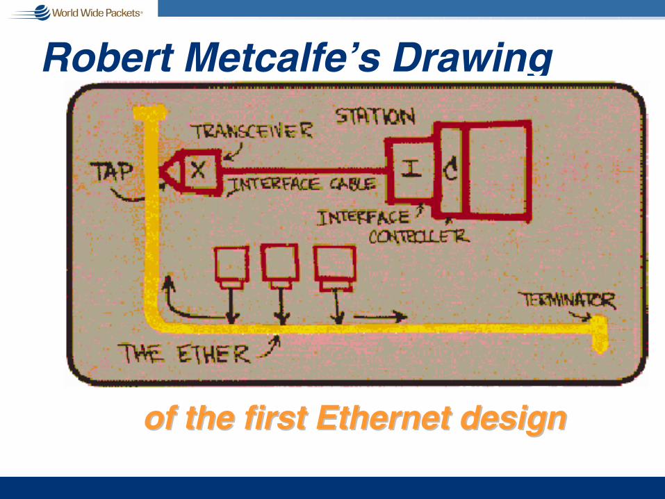
Robert Metcalfe’s Drawing
of the first Ethernet designof the first Ethernet design

How CSMA/CD Works – Party Line
g Is anyone on line?n If yes, try again latern If no, ring the address
you want to talk with
g Did anyone else try to get on “at the same time” you did?
n If yes, try again latern If no, you own the
media

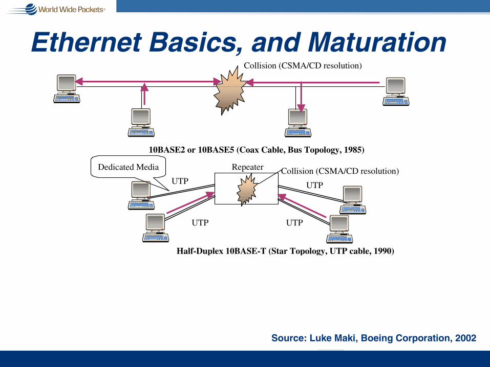
Ethernet Basics, and Maturation
10BASE2 or 10BASE5 (Coax Cable, Bus Topology, 1985)
Collision (CSMA/CD resolution)
Collision (CSMA/CD resolution)Repeater
UTP
UTP
UTP
UTP
Half-Duplex 10BASE-T (Star Topology, UTP cable, 1990)
Bridge/Switch
Full Duplex 10/100BASE-T (1992/1993) Collision-Free
Dedicated Media
UTP UTP
CSMA/CD:
Carrier Sense Multiple Access with Collision Detection
Source: Luke Maki, Boeing Corporation, 2002
Ethernet Basics, and Maturation
10BASE2 or 10BASE5 (Coax Cable, Bus Topology, 1985)
Collision (CSMA/CD resolution)
Collision (CSMA/CD resolution)Repeater
UTP
UTP
UTP
UTP
Half-Duplex 10BASE-T (Star Topology, UTP cable, 1990)
Bridge/Switch
Full Duplex 10/100BASE-T (1992/1993) Collision-Free
Dedicated Media
UTP UTP
Source: Luke Maki, Boeing Corporation, 2002

Ethernet Basics, and Maturation
10BASE2 or 10BASE5 (Coax Cable, Bus Topology, 1985)
Collision (CSMA/CD resolution)
Collision (CSMA/CD resolution)Repeater
UTP
UTP
UTP
UTP
Half-Duplex 10BASE-T (Star Topology, UTP cable, 1990)
Bridge/Switch
Full Duplex 10/100BASE-T (1992/1993) Collision-Free
Dedicated Media
UTP UTP
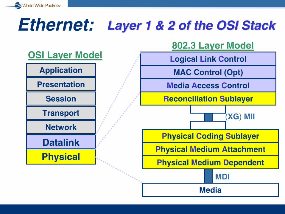
Ethernet:
Application
Presentation
Session
Transport
Network
Datalink
Physical
OSI Layer Model Logical Link Control
Physical Medium Dependent
Physical Coding Sublayer
Physical Medium Attachment
MAC Control (Opt)
(XG) MII
Reconciliation Sublayer
Media Access Control
Media
802.3 Layer Model
MDI
Layer 1 & 2 of the OSI StackLayer 1 & 2 of the OSI Stack
802 Overview & Architecture
802
Over-view
Archi-tecture
802.1
Mana-gement
802.3
CSMA/CD
802.2 Logical Link ControlIEEE Std 802.2, ISO 8802-2-1989
802.1 MAC BridgingIEEE Std 802.1D;1990
802.4
TBUS
802.5
TRING
802.6
DQDB
802.9
ISLAN
802.11
WLAN
802.12
DPAP
802.14
CATV
802.15
WPAN
802.16
BWA
802.17
RPR
OSILayer
2
OSILayer
1
802.10
SILS
IEEE
ISO ISO ISO
802.7 Broadband TAG (BBTAG) IEEE 802.7-1989
802.8 Fiber Optic TAG (FOTAG) IEEE 802.8-1987Ethernet

IEEE 802 Working Groups802.1 Higher Layer LAN Protocols Working Group802.2 Logical Link Control Working Group (Inactive) 802.3 Ethernet Working Group 802.4 Token Bus Working Group (Inactive)
802.5 Token Ring Working Group (Inactive)
802.6 Metropolitan Area Network Working Group (Inactive)
802.7 Broadband TAG (Inactive)
802.8 Fiber Optic TAG (Disbanded)
802.9 Isochronous LAN Working Group (Inactive)
802.10 Security Working Group (Inactive)
802.11 Wireless LAN Working Group
802.12 Demand Priority Working Group (Inactive)
802.13 Not Used
802.14 Cable Modem Working Group (Inactive)
802.15 Wireless Personal Area Network (WPAN) Working Group
802.16 Broadband Wireless Access Working Group 802.17 Resilient Packet Ring Working Group
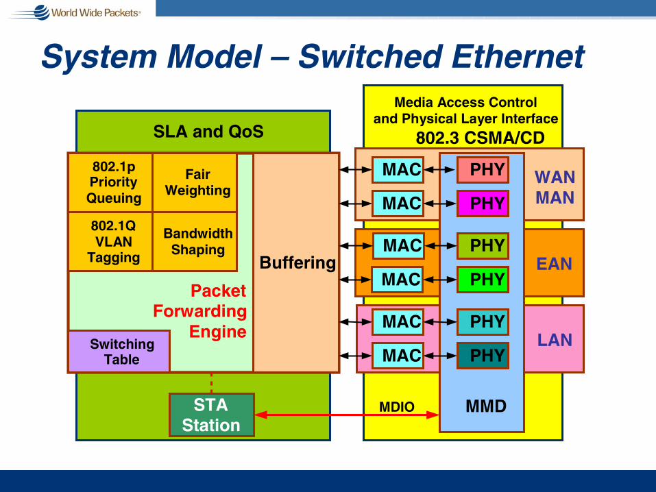
System Model – Switched Ethernet
Buffering
FairWeighting
802.1pPriorityQueuing
BandwidthShaping
802.1QVLAN
Tagging
PacketForwarding
EngineSwitching
Table
SLA and QoS 802.3 CSMA/CD
Media Access Controland Physical Layer Interface
STAStation
MAC
MAC
MAC
MAC WANMAN
EAN
MAC
MACLAN
PHY
PHY
PHY
PHY
PHY
PHY
MMDMDIO

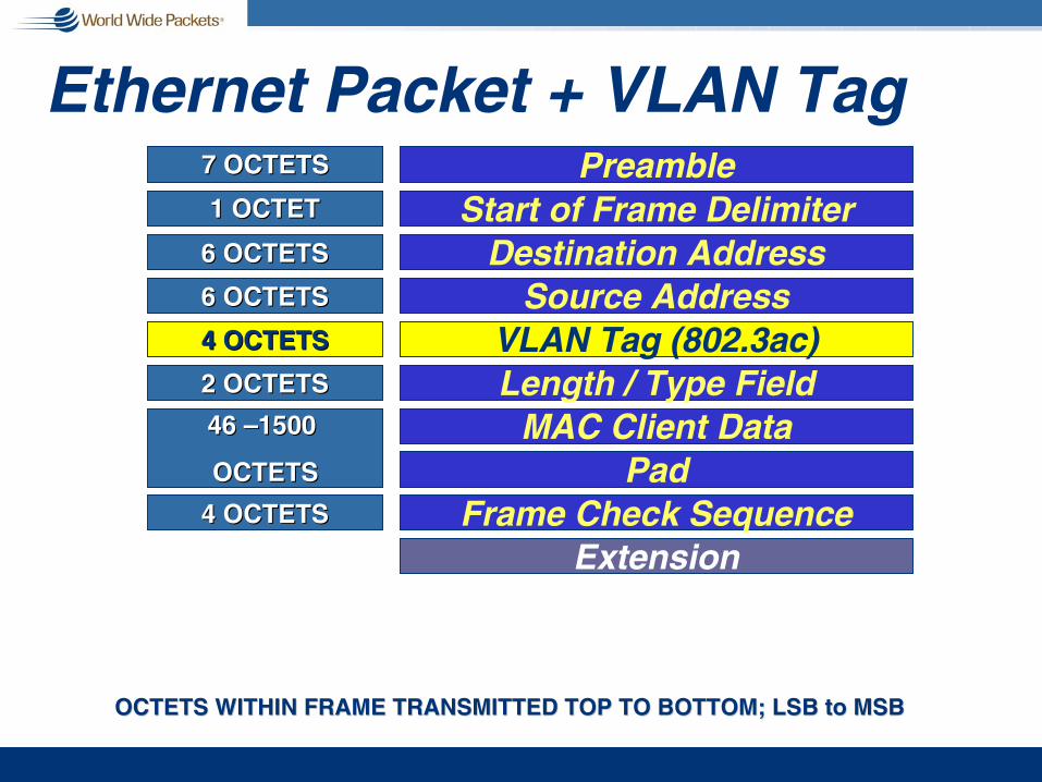
The Ethernet Packet
OCTETS WITHIN FRAME TRANSMITTED TOP TO BOTTOM; LSB to MSBOCTETS WITHIN FRAME TRANSMITTED TOP TO BOTTOM; LSB to MSB
ExtensionFrame Check Sequence
PadMAC Client Data
Source AddressDestination Address
Preamble
Length / Type Field
4 OCTETS4 OCTETS
46 46 ––1500 1500
OCTETSOCTETS
6 OCTETS6 OCTETS
6 OCTETS6 OCTETS
7 OCTETS7 OCTETS
2 OCTETS2 OCTETS
Start of Frame Delimiter1 OCTET1 OCTET
Ethernet Packet + VLAN Tag
VLAN Tag (802.3ac)4 OCTETS4 OCTETS
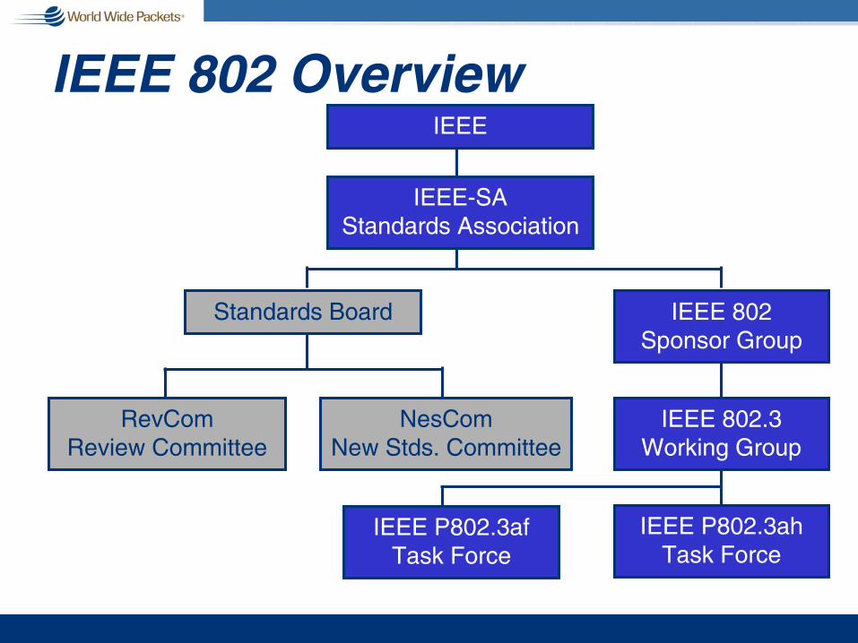
IEEE 802 OverviewIEEE
IEEE-SAStandards Association
Standards Board IEEE 802Sponsor Group
RevComReview Committee
IEEE 802.3Working Group
IEEE P802.3ahTask Force
IEEE P802.3afTask Force
NesComNew Stds. Committee
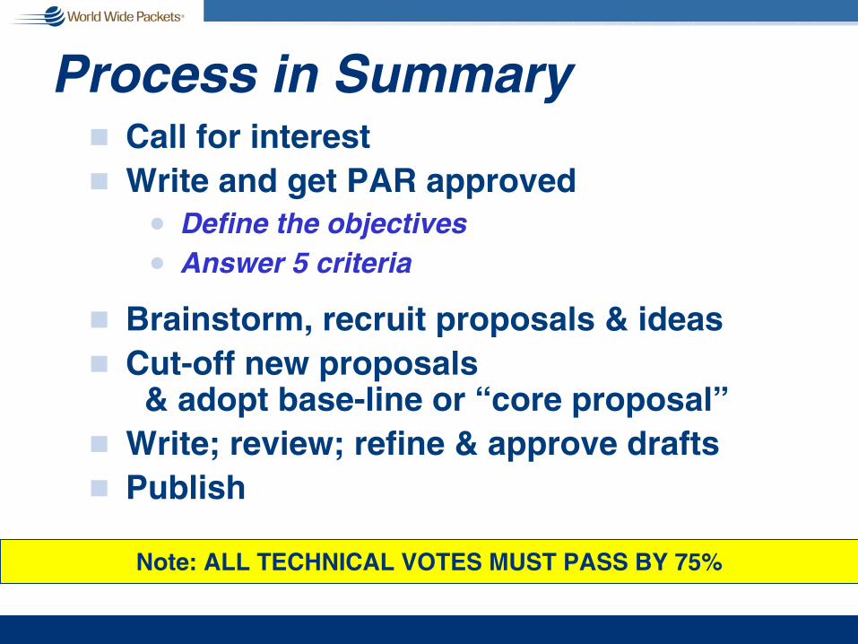
Process in Summaryg Call for interestg Write and get PAR approved
n Define the objectivesn Answer 5 criteria
g Brainstorm, recruit proposals & ideasg Cut-off new proposals
& adopt base-line or “core proposal”g Write; review; refine & approve draftsg Publish
Note: ALL TECHNICAL VOTES MUST PASS BY 75%

The 5 Criteria1. Broad Market Potential
Broad set(s) of applications // Multiple vendors, multiple usersbalanced cost, LAN vs.. attached stations
2. Compatibility with IEEE Standard 802.3Conformance with CSMA/ CD MAC, PLS // Conformance with 802.2
3. Distinct IdentitySubstantially different from other 802.3 specs/ solutionsUnique solution for problem (not two alternatives/ problem)Easy for document reader to select relevant spec
4. Technical FeasibilityDemonstrated feasibility; reports -- working modelsProven technology, reasonable testing // Confidence in reliability
5. Economic FeasibilityCost factors known, reliable data // Reasonable cost for performance expected // Total Installation costs considered

Other Things Ethernet…There is a strong cultural history to:g Leave the MAC aloneg Provide 10X performance at 3-4X the costg Minimize number of PHYs per media typeg Develop a standard that guarantees
interoperability == “plug and play”g Spec 10e-12 BER;
n Expect better than 10e-15
g Attempt to achieve 100% consensus
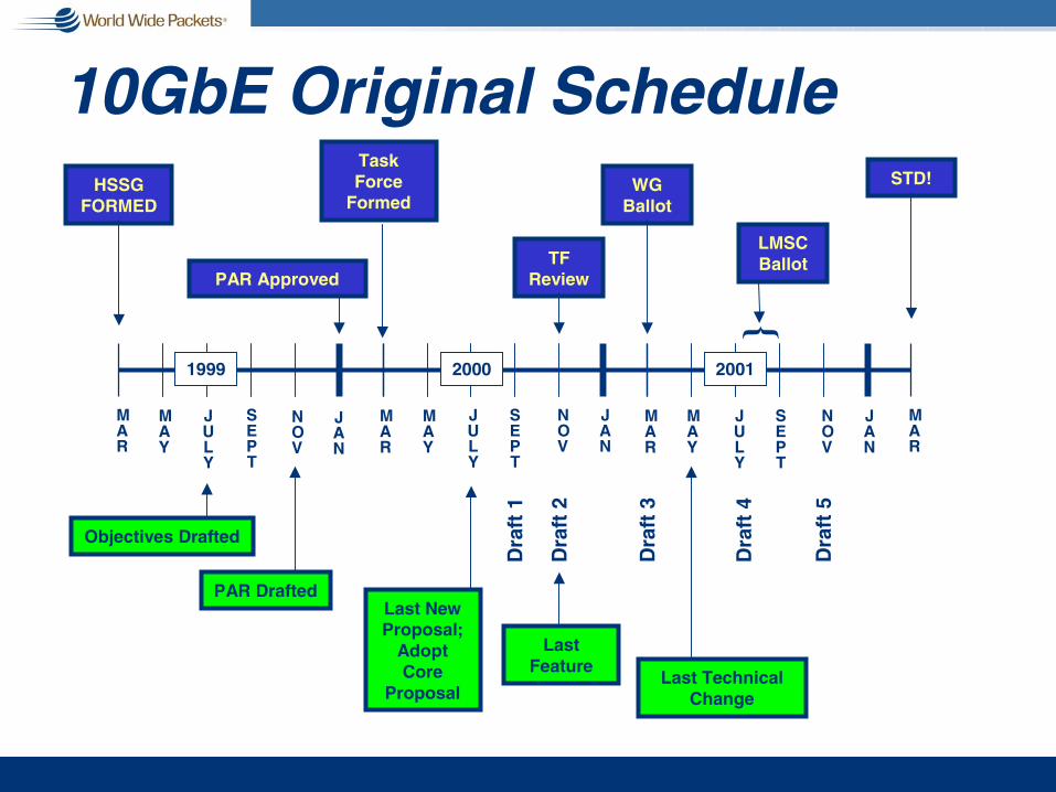
10GbE Original Schedule
MAR
MAY
JULY
SEPT
NOV
JAN
MAR
MAY
JULY
SEPT
NOV
JAN
MAR
MAY
JULY
SEPT
NOV
JAN
1999 2000 2001
HSSGFORMED
TaskForce
Formed
PAR Drafted
Objectives Drafted
STD!
LMSC Ballot
Last Technical Change
WG Ballot
TF Review
Last Feature
Last New Proposal;
Adopt Core
Proposal
Dra
ft 1
Dra
ft 2
Dra
ft 3
Dra
ft 4
Dra
ft 5
MAR
PAR Approved
}

10GbE Schedule Accompli
MAR
MAY
JULY
SEPT
NOV
JAN
MAR
MAY
JULY
SEPT
NOV
JAN
MAR
MAY
JULY
SEPT
NOV
JAN
1999 2000 2001
HSSGFORMED
TaskForce
Formed
Par Drafted
Objectives Drafted
STD!
LMSC Ballot
Last Technical Change
WG Ballot
TF Review
Last Feature
Last New Proposal;
Adopt Core
Proposal
Dra
ft 1
Dra
ft 2
Dra
ft 3
MAR
PAR Approved
Dra
ft 1
.1
Dra
ft 2
.1
Dra
ft 4
.0
Dra
ft 4
.2
Dra
ft 3
.1
Dra
ft 3
.2
Dra
ft 3
.3D
raft
3.4
Dra
ft 4
.1
MAY
JULY
Dra
ft 5
.0D
raft
4.3

IEEE 802.3 Ballot ProcessRevCom & IEEE Standards Board
802 (LMSC or Sponsor)
802.3 Working Group
802.3** Task Force (e.g., 802.3ah == EFM)
Approve
Ret
urn
wit
h c
om
men
t ApprovedStandard
Approve
Approve

10GbE Sponsor Ballot Results
82%
8%
76%
D4.0
82%
5%
79%
D4.1
96%88%86%Approve
4%5%5%Abstain
87%85%83%Return
D5.0D4.3D4.2Voters: 109

NOT YOUR
FATHER’SETHERNET

Enterprise Networkingg Dumb terminals
n attached to mainframes
g Star wiredg Relatively short
distancesg High reliabilityg Easy to maintaing Lowest cost (?)g Mission critical
Note: IEEE 802 formed in 1980
circa 80circa 80
Ethernet – CSMA/CDg Carrier sense multiple
access with collision detectionn Simplex operation
g Shared media (taps)g Relatively short
distanceg Low reliabilityg Difficult to maintaing Difficult to upgradeg Lowest cost (?)g Applications?
True of all immatureshared media topologies
circa 83circa 83

Enterprise Networkingg Dumb terminal
emulation cards in PCsg Still mission criticalg Enter LOTUS 1-2-3
Sneakernet
circa 85circa 85

Enterprise Networkingg Dumb terminal
emulation cards still in PCs (mission critical)
g Ethernet cards also (PC-based SW becoming mission critical)
g > 2x the workg < ½ the reliabilityg > 2x the expense
circa 86circa 86

Ethernet Hubsg CSMA/CD – Half Duplex
n Star wiredn Point-to-point onlyn No shared median But, protocol behaves
like shared media
g Increased distanceg Higher reliabilityg Easier to maintaing Easy upgrade pathg Higher cost
circa 85circa 85--8686
10
10
1010
10
10
Switched Ethernetg Full Duplex
n No collisions!
n Star wired
n Point-to-point only
n No shared media
n Transmitter does not monitor Rcvr
g Increased distanceg Highest reliabilityg Easiest to maintaing Easiest to upgradeg Higher costg Higher performance
circa 87circa 87
10
10
1010
10
10

Fiber Optic Inter-Repeater Link
Repeater Set
Repeater Set
Repeater Set
MAUDTE
MAUDTE
10BASE-T Link Segments
Fiber Optic Link Segments
FOIRLFOIRL

Fiber Optic Inter-Repeater Linkg 10BASE-F Clauses 15-18 g Star Wired; g Distance
n 10BASE-FP: 1 km; Half Duplexn 10BASE-FB: 2 km; Half Duplexn 10BASE-FL: 2 km; Half or Full Duplexn Other distances apply with multiple segments
g 850 nm LED; 62.5/125 MMFg BER 10e-9g 802.3d-1987 (9.9)g 10 December 1987 (IEEE)
FOIRLFOIRL

10BASE-Tg Inexpensive mediag Inexpensive portsg Installation ease
10
10
1010
10
10
circa 90circa 90
Enterprise Networkingg Dumb terminals goneg Emulators built into
PC SW for legacy applications
g Mainframes on FDDI rings
g Wide area connection via T1 lines
g Serious application of shared storage
g Serious DB applications
10
10
1010
10
10
circa 90circa 90

Fast Ethernet – 100BASE-X
100 100
100
10 10
1010
10
1010
Introduction of multiIntroduction of multi--speed topologiesspeed topologies

Fast Ethernet – 100BASE-XIEEE 802.3ug Pretty much a shift in decimal place from 10BASE-T
g CSMA/CD + Full Duplex
g Cat 3… Cat 5 Copper Technology (100BASE-T)
g Optical technology from FDDI (100BASE-FX)n 2 km over MMFn (10 km over SMF)
g Introduces high speed aggregation between switches
Sorry Token Ring

100BASE-FX26.2 Functional Specificationsg The 100BASE-FX PMD (and MDI) is specified by
incorporating the FDDI PMD standard, ISO/IEC 9314-3: 1990, by reference…
g Total of 2 pages (excluding PICS)
Characteristicsg Star Wired (not counter-rotating ring)g 1310 nm LED over 62.5/125 MMF
n 50 MMF SMF with laser outside std
g NRZ: Bit Transition = 1; No Transition = 0g 100 Mbps data rate; 10e-8 BERg 125 Mbps using 4B/5B encoding line rate
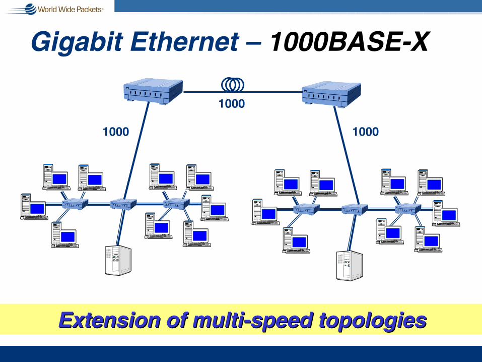
Gigabit Ethernet – 1000BASE-X
1000
1000 1000
Extension of multiExtension of multi--speed topologiesspeed topologies

Gigabit Ethernet IEEE 802.3zg CSMA/CD + Full Duplexg Carrier Extensiong Serial technology from Fibre Channel
n 1000BASE-CX copper, Twin-ax, generally unused
n 1000BASE-SX 850 nm, MMF
n 1000BASE-LX 1310 nm, SMF/MMF
n Uses 8B/10B code
IEEE 802.3abg Support of CAT-5 (CAT-5E) cable: 1000BASE-T
Sorry ATM

Fast Ethernet to GigE Upgrade
See: http://www.10gea.org/Tech-whitepapers.htm

1000BASE-TIEEE 802.3abg Supports both full & half duplex (CSMA/CD)
n But, no one uses CSMA/CD mode at 1 Gig
g 1000Mbps Ethernet service over 100 meters of same Category 5 links ANSI/TIA/EIA-568-A. 100BASE-T.
g Same auto-negotiation system as 100BASE-TXn Enable PHYs capable of both 100 and 1000 Mbps
g Specifications for field testing of twisted pair cabling system with the additional test parameters for FEXT (ELFEXT)

250 Mbps Bi-Directional on Each Pair

The Challenge: NEXT & FEXT

Gigabit Ethernet Beyond Campusg IEEE 802.3z specifies 5km over SMF
g Transceivers extended distance & bandwidth:n 10 km, 1310 nm, SMF immediately (LX++)n 40 km, 1550 nm, within 1 year (proprietary, common pkg)n 100 km within 2 yearsn 4 Gbps using 802.3ad and WDM in 3 yrs (> 40 km)
g Ownership significantly less than cost of T1/ATM/SONET…
n Spokane school district (GigE to every school over fiber)n CANARIE project (see www.canarie.ca)
g Spawns new market segmentsn Yipes, Telseon, OnFiber…n Grant County, WA; Provo, UT; Jacksonville, FL….
Link AggregationIEEE 802.3adg Ability to take N links between common
nodes – point-to-point – and aggregate a subset as virtual link
g Ideal for intermediate speeds….
g Ideal for TDM & WDM – non-standard –solutions
g Utilization of the N * Serial conceptn Started in HIPPI for 10Gig
n 12 x 1 Gig parallel opticsn circa 1994?

10 Gigabit EthernetIEEE 802.3aeg MAC: It’s Just Ethernet
n Maintains 802.3 frame format & sizen Full duplex operation onlyn Throttled to 10.0 for LAN PHY or 9.58464 Gbps for WAN PHY
g PHY: LAN & WAN PHYsn LAN PHY uses simple encoding mechanisms to transmit data
on dark fiber & dark wavelengthsn WAN PHY adds a SONET framing sublayer
to utilize SONET/SDH as layer 1 transport
g PMD: Optical Media Onlyn 850 nm on variety of MMF types (28m…) to 300mn 1310 nm, 4 lambda, WDM to 300 m on MMF; 10 km on SMFn 1310 nm on SMF to 10 kmn 1550 nm on SMF to 40 km
1 of 2
10 Gigabit Ethernetg Supports dark wavelength and SONET/TDM
with unlimited reachg Several coding schemes – 64b/66b; 8B/10B;
scramblersg Three optional interfaces: XGMII; XAUI; XSBIg Extension of MDIO interfaceg Continues Ethernet’s reputation for cost effectiveness
& simplicity – goal 10X performance for 3X costg Standard ratified in June 2002g Business and economic success TBD
Sorry Who?
2 of 2

Overview of DTE Power

P802.3af DTE Powerg AKA “Power over Ethernet”
g Provides up to 13W to a connected devicen IP phonen Web camn Wireless access pointn Security, lighting, HVAC controlsn Enables many new types of devices
g Supports 10, 100, 1000BASE-T n Power over signal pairs orn Power over “idle” pairs
g Eliminates the need for AC power to devicesn No “wall warts”n No expensive AC power wiring for wireless access points
1 of 3
P802.3af DTE Powerg Power supply equipment
n Powered hub or switch ORn Mid-span insertion unit
g Allows for flexible UPS strategies
g Provides “discovery” of DTE-capable devicen Power only applied when proper “signature” is detectedn Will not harm legacy equipmentn Works with existing 2 or 4 pair cable plant
g Project Statusn Task force formed January 2000n Draft in working group ballot nown Published standard early 2003n Broad industry support
2 of 3

P802.3af DTE Powerg First “world–wide” standard for power
distributionn IP Phonen The Ethernet shaver!
3 of 3
Overview ofEthernet in the First
Mile

Ethernet in the First Mile

GbE LX vs.. Single Fiber P2P

P2P Focus

P2MP (EPON) Downstream

P2MP (EPON) Upstream

EFM Copper (Unclassified)

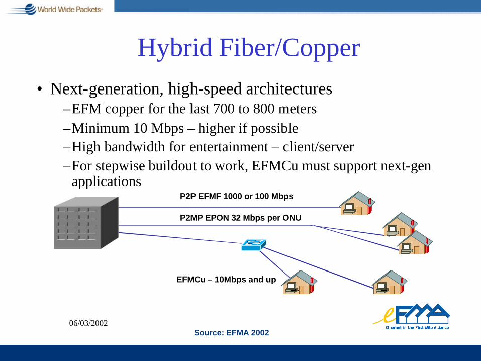
06/03/2002
• Next-generation, high-speed architectures–EFM copper for the last 700 to 800 meters–Minimum 10 Mbps – higher if possible–High bandwidth for entertainment – client/server–For stepwise buildout to work, EFMCu must support next-gen
applicationsP2P EFMF 1000 or 100 Mbps
P2MP EPON 32 Mbps per ONU
EFMCu – 10Mbps and up
Source: EFMA 2002
Hybrid Fiber/Copper
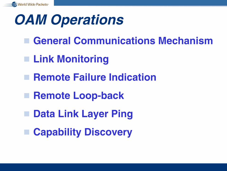
OAM Operationsg General Communications Mechanism
g Link Monitoring
g Remote Failure Indication
g Remote Loop-back
g Data Link Layer Ping
g Capability Discovery

New Concepts in Current Projectsg Powering devices over UTP-5g Variable data rate MACg Embedded Framer within PCSg Use of SONET as Layer 1 transportg Embedded BERT within PCSg High speed differential, multi-lane, bus (XAUI)g Use of WDMg Extend link length to 40 kmg Single fiber, full duplex PHYg Support of unclassified twisted pairg OAMg Extended temperature operationg Extension into Metro, Backbone, and Access
Spaces

10 Gigabit Ethernet in Detail

10 GbE Layer Diagram
Media Access Control (MAC)Full Duplex
Media Access Control (MAC)Full Duplex
WWDMPMD
1310 nm
SerialPMD
850 nm
WWDM LAN PHY(8B/10B)
10 Gigabit Media Independent Interface (XGMII) or10 Gigabit Attachment Unit Interface (XAUI)
10 Gigabit Media Independent Interface (XGMII) or10 Gigabit Attachment Unit Interface (XAUI)
SerialLAN PHY(64B/66B)
SerialPMD
1310 nm
SerialPMD
1550 nm
SerialPMD
850 nm
SerialPMD
1310 nm
SerialPMD
1550 nm
SerialWAN PHY
(64B/66B + WIS)
-LX4 -SR -LR -SW -LW -EW-ER

IEEE P802.3ae Objectivesg Preserve 802.3 Ethernet frame formatg Preserve 802.3 min/max frame sizeg Full duplex operation onlyg Fiber cabling onlyg 10.0 Gbps at MAC-PHY interfaceg LAN PHY data rate of 10 Gbpsg WAN PHY data rate of ~9.29 Gbps

802.3ae Detailed Objectivesg Preserve the 802.3/Ethernet frame format at the MAC client
service interface
g Meet 802 functional requirements, with the possible exception of hamming distance
g Preserve minimum and maximum FrameSize of current 802.3 standard
g Support full-duplex operation only
g Support star-wired local area networks using point-to-point links and structured cabling topologies
g Specify an optional media independent interface
g Support proposed standard P802.3ad (link aggregation)
g Support a speed of 10.000 Gbps at the MAC/PLS service interface
1 of 2

802.3ae Detailed Objectivesg Define two families of PHYs
n A LAN PHY, operating at a data rate of 10.000 Gbpsn A WAN PHY, operating at a data rate compatible with the payload
rate of OC-192c/SDH VC-4-64c
g Define a mechanism to adapt the MAC/PLS data rate to the data rate of the WAN PHY
g Provide physical layer specifications which support link distances of:
n At least 65 m over MMF n At least 300 m over installed MMFn At least 2, 10, and 40 km over SMF
g Support fiber media selected from the second edition of ISO/IEC 11801 (802.3 to work with SC25/WG3 to develop appropriate specifications for any new fiber media)
2 of 2
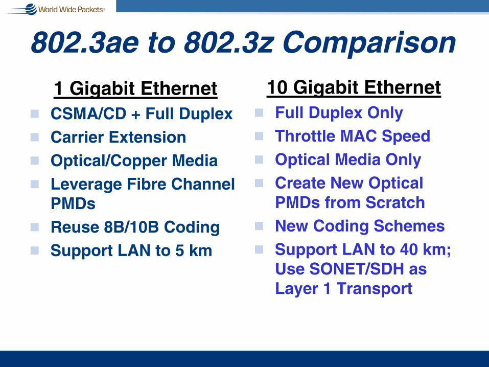
802.3ae to 802.3z Comparison1 Gigabit Ethernet
g CSMA/CD + Full Duplexg Carrier Extensiong Optical/Copper Mediag Leverage Fibre Channel
PMDsg Reuse 8B/10B Codingg Support LAN to 5 km
10 Gigabit Ethernetg Full Duplex Onlyg Throttle MAC Speedg Optical Media Onlyg Create New Optical
PMDs from Scratchg New Coding Schemesg Support LAN to 40 km;
Use SONET/SDH as Layer 1 Transport
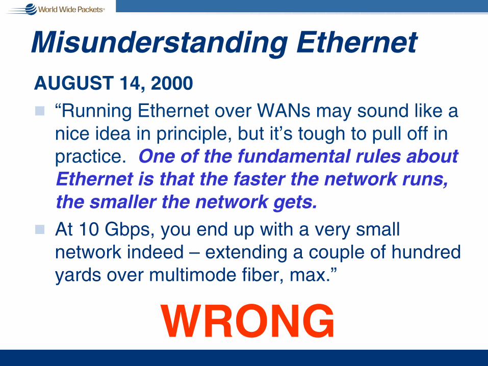
Misunderstanding EthernetAUGUST 14, 2000g “Running Ethernet over WANs may sound like a
nice idea in principle, but it’s tough to pull off in practice. One of the fundamental rules about Ethernet is that the faster the network runs, the smaller the network gets.
g At 10 Gbps, you end up with a very small network indeed – extending a couple of hundred yards over multimode fiber, max.”
WRONG

802.3ae
!!!!LAN
!!!!!!!!MAN
!!!!!!!!RAN
!!!!!!!!WAN
!!!!LAN PHY
WAN PHY

Bandwidth/Distance Evolution
0.1 1 10 100 1000 Distance (kilometers)
Ban
dwid
th (
Mb
ps
)1
10 1
00
1,
000
1
0,00
0
Ethernet
Fast Ethernet
Gigabit Ethernet
10 Gigabit Ethernet

PMD Distances SupportedSMF50 MMF62.5 MMFFiber
300m @500MHz*km
-
-
28m
160
-
-
35m
200
40 km---ER/EW1550 nm
10 km-300m240LX41310 nm
10km---LR/LW1310 nm
-300m86m69mSR/SW850 nm
-2000500400MHz*km

10 GbE Applications
DWDM Optical Network
10GBASE-LX4 or -LR
Campus Link
Enterprise A
10GBASE-LW or -EWMetro Link
Campus X
10GBASE-LR, -ER, -LW, or -EW
Metro Link
Enterprise B
Campus Y
Enterprise C
ServerFarm
10GBASE-SWJumper
10GBASE-SRJumper
10GBASE-LR, -ERMetro Link

10 GbE in the LAN10 GbE in:
SP data centers & enterprise LANs
n Switch-to-switchn Switch-to-servern Data centersn Between buildings
ServerFarm
10GbE
Data Center
Campus A
Campus B
10GbE
10GbE
10GbE
InternetExtranet

10 GbE in the MAN over DWDMEnterprises: g 10 GbE enables server-less
buildings remote backup disaster recovery
Service Providers: g 10 GbE enables dark
wavelength Gigabit services at costs less than T3 or OC-3
MAN DWDM Optical Network
Location B
Location A
10GbE
Remote Servers
Location C
10GbE
10GbE
DWDM mux

Location B
Location A
10GbE
10GbE
MetroMetro
Remote Servers
Location C
10GbE
10GbE
10GbE
10GbE
10 GbE in the MANover Dark Fiberover Dark Fiber
MetropolitanNetworks

Carrier DWDM device collocatedwith SP 10 GbE Switch
Core DWDM Core DWDM Optical NetworkOptical Network
10GbE
Service Provider Point of Presence
(PoP)CarrierCentral
Office (CO)
10GbEOpticalTransport
OpticalTransport
CarrierCentral
Office (CO)
Service Provider Point of Presence
(PoP)
10 GbE in the WANg Attachment to the optical cloudg Compatibility with the installed base of SONET STS-
192c/SDH VC-4-64c
NationalBackbone
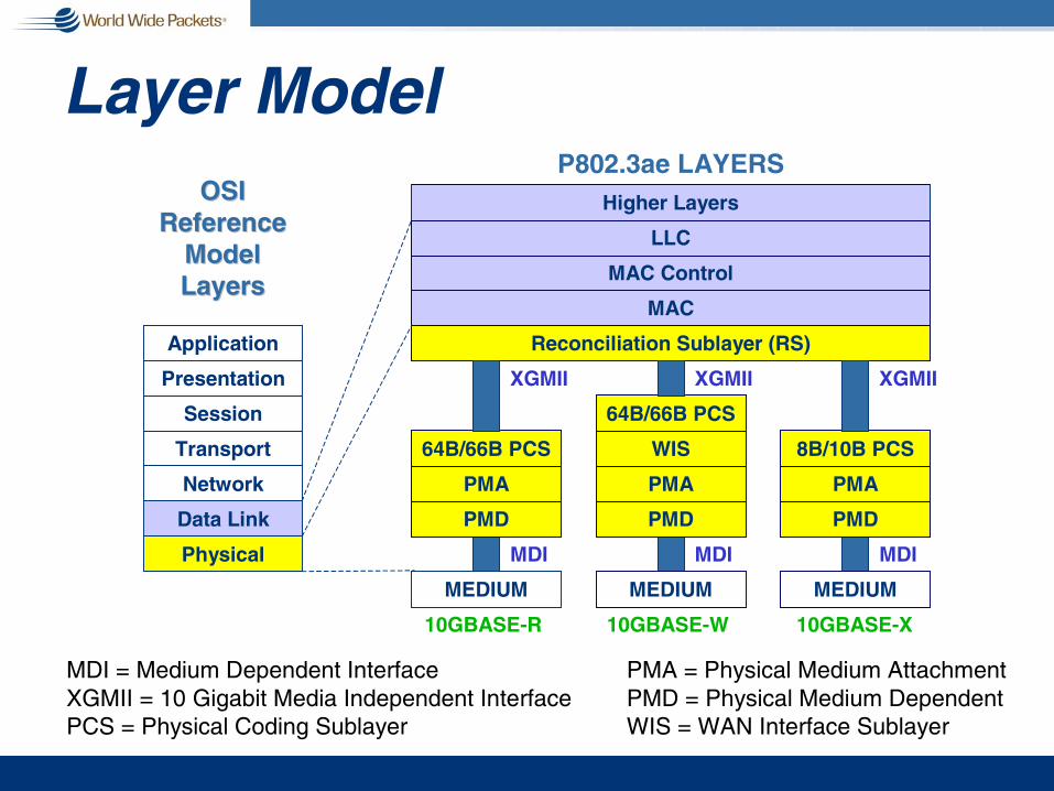
Layer Model
Application
Presentation
Session
Transport
Network
Data Link
Physical
PMD
PMA
64B/66B PCS
PMD
PMA
8B/10B PCS
Reconciliation Sublayer (RS)
MAC
MAC Control
LLC
Higher LayersOSIOSIReferenceReference
ModelModelLayersLayers
MEDIUM MEDIUM
P802.3ae LAYERS
XGMII XGMII
MDI MDI
MDI = Medium Dependent InterfaceXGMII = 10 Gigabit Media Independent InterfacePCS = Physical Coding Sublayer
PMA = Physical Medium AttachmentPMD = Physical Medium DependentWIS = WAN Interface Sublayer
10GBASE-R 10GBASE-X
PMD
PMA
WIS
64B/66B PCS
MEDIUM
XGMII
MDI
10GBASE-W

Device Nomenclature
!!!!!!!!!!!!!!!!!!!!!!!!10GBASE-EW
!!!!!!!!!!!!!!!!10GBASE-ER
!!!!!!!!!!!!!!!!!!!!!!!!10GBASE-LW
!!!!!!!!!!!!!!!!10GBASE-LR
!!!!!!!!!!!!!!!!!!!!!!!!10GBASE-SW
!!!!!!!!!!!!!!!!10GBASE-SR
1550
nmSe
rial
1310
nmSe
rial
1310
nmW
WDM
850n
mSe
rial
WIS
64B/6
6BPC
S
8B/1
0BPC
SDevice
!!!!!!!!!!!!!!!!10GBASE-LX4
Logic Optics

10GBASE-XEthernet Packet + Min. IPG
XGMIIXGMII
8b8b8b8b
10 Gbps
10 Gbps
8B/10BEncoder
10b 12.5 Gbps,4 @ 3.125 Gbps
SERDES12.5 Gbps,
4 @ 3.125 Gbps
8B/10BEncoder
8B/10BEncoder
8B/10BEncoder
10b
SERDES
10b
SERDES
10b
SERDES
MACMAC
10GBASE10GBASE--XX
PMAPMA
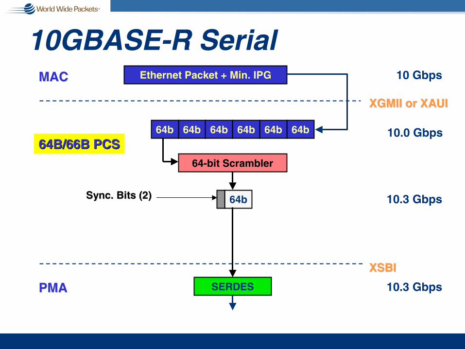
10GBASE-R SerialEthernet Packet + Min. IPGMACMAC
64b
XGMII or XAUIXGMII or XAUI
64b64b64b64b64b
64B/66B PCS64B/66B PCS
10 Gbps
64-bit Scrambler
64bSync. Bits (2)Sync. Bits (2)
XSBIXSBI
SERDES
10.0 Gbps
10.3 Gbps
10.3 GbpsPMAPMA

The 10 Gigabit Ethernet LAN
g Faster: 10X
g Further: 40 km (expect proprietary extensions or WAN)
g Format: No change; same size packet
g Management: Consistent
Simple, Predictable, Elegant

9.29 GbpsExtra IPG Dumped
9.58 Gbps
9.95 Gbps
10GBASE-W SerialEthernet Packet + Min. IPG
64b
XGMII or XAUIXGMII or XAUI
64b64b64b64b64b
10 Gbps
64-bit Scrambler
64bSync. Bits (2)Sync. Bits (2)
XSBIXSBI
SERDES
Extra IPG
Simplified SONET Framer 9.95 GbpsWISWIS
MACMAC
64B/66B PCS64B/66B PCS
PMAPMA

Interfacesg XGMII (10G Media Independent I/F)
n 4 byte-wide lanes with 1 control bit per lane
g XAUI (10G Attachment Unit I/F)n Extends XGMII reach (3” vs. 20”)n 4 differential lanes at 3.125 Gbps
g XSBI (10G Sixteen-Bit Interface)n Based on the OIF SFI-4 interfacen 16 differential signals at 622-645 Mbps

XGMII Extender
g XGXS - XAUI - XGXS blocks can be used to extend the XGMII with any PHY
g With LAN WWDM, the PHY-side XGXS & the 8B/10B PCS+PMA simplified to a re-timer
XGXS8B/10B
XGMII
XGXS8B/10B
XAUI XGMII

The 10 Gigabit Ethernet LAN
g Faster: 10X
g Further: 40 kmn expect proprietary extensions on WAN
g Format: No change; same size packet
g Management: Consistent
Simple, Predictable, Elegant

‘Path,’ ‘Line,’ ‘Section’
Section Section
Line
Path(s)
Stratum Clock
Regenerator(STE)
LocalClock
LocalClock
Note: A Line can be longer than two sections
Path TerminatingEquipment
(PTE)
Path TerminatingEquipment
(PTE)
Path TerminatingEquipment
(PTE)
Path TerminatingEquipment
(PTE)Path
TerminatingEquipment
(PTE)
Path TerminatingEquipment
(PTE)
Path TerminatingEquipment
(PTE)
Path TerminatingEquipment
(PTE)
Line TerminatingEquipment
(LTE)
Line TerminatingEquipment
(LTE)
http://grouper.ieee.org/groups/802/3/ae/public/terminology.pdf
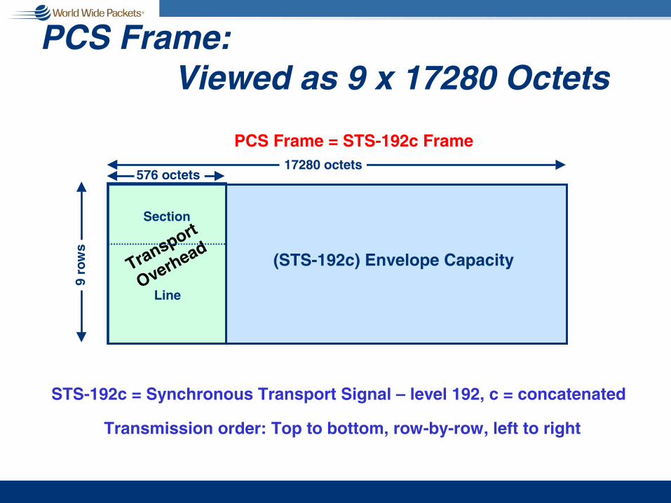
576 octets
(STS-192c) Envelope CapacityTransport
Overhead
17280 octets
9 ro
ws
PCS Frame = STS-192c Frame
STS-192c = Synchronous Transport Signal – level 192, c = concatenated
Transmission order: Top to bottom, row-by-row, left to right
Line
Section
PCS Frame: Viewed as 9 x 17280 Octets

1 1664063
576 octets
Payload Capacity – 9.58464 Gbps
(STS-192c) Envelope Capacity
(STS-192c) SPE
PCS data stream
Path Overhead column
Payload CapacityFixedStuff
17280 octets
9 ro
ws
packet
IDLE
IDLE IDLE
packetIDLE
PCS Frame = STS-192c Frame
9 ro
ws
16704 octets
STS-192c = Synchronous Transport Signal – level 192, c = concatenatedSPE = Synchronous Payload Envelope
Line
Section
FixedStuff
Transport
Overhead
packet IDLEIDLE packet
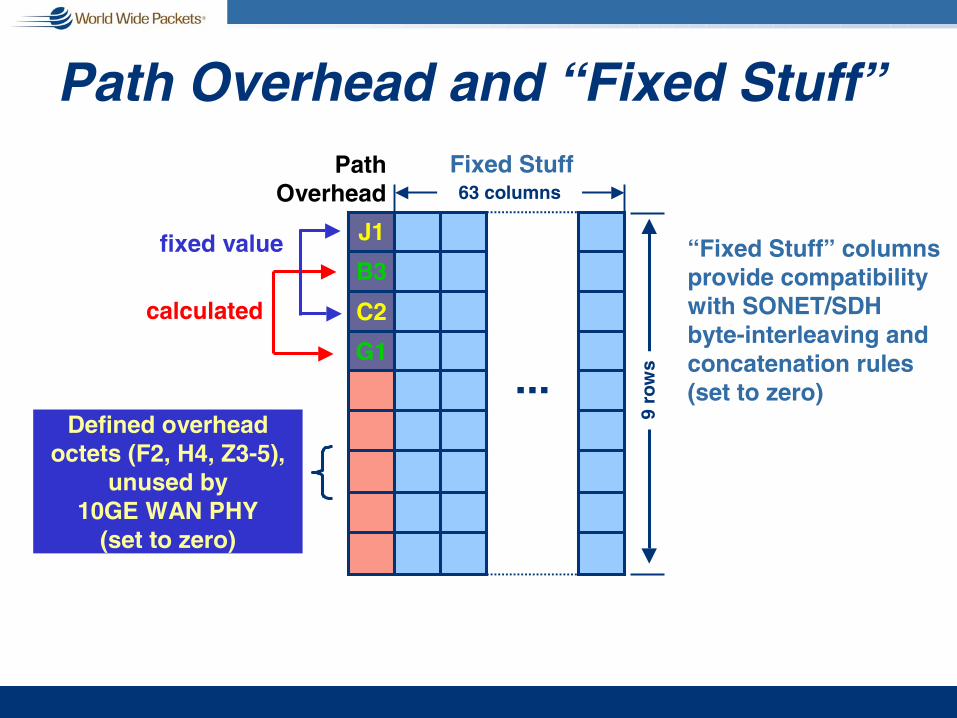
Path Overhead and “Fixed Stuff”
J1
B3
C2
G1
PathOverhead
calculated
fixed value
Defined overheadoctets (F2, H4, Z3-5),
unused by10GE WAN PHY
(set to zero)
Fixed Stuff63 columns
...
“Fixed Stuff” columnsprovide compatibilitywith SONET/SDHbyte-interleaving andconcatenation rules(set to zero)
9 ro
ws
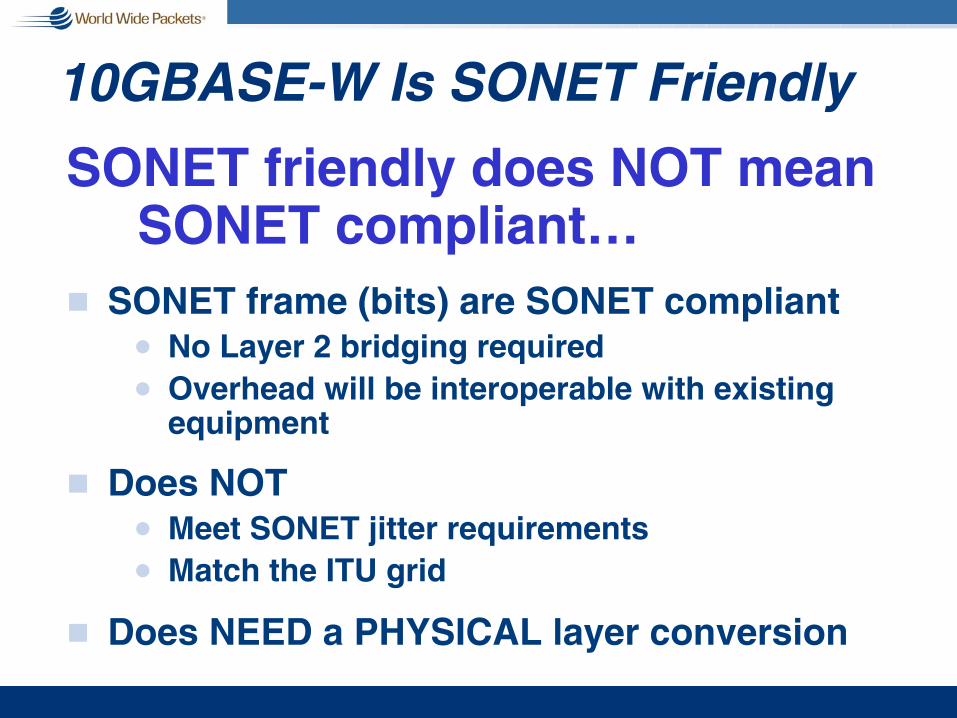
10GBASE-W Is SONET Friendly
SONET friendly does NOT mean SONET compliant…
g SONET frame (bits) are SONET compliantn No Layer 2 bridging requiredn Overhead will be interoperable with existing
equipment
g Does NOT n Meet SONET jitter requirementsn Match the ITU grid
g Does NEED a PHYSICAL layer conversion

Test Patternsg Required – Built in
n Pattern A seed: 0x3C8B44DCAB6804Fn Pattern B seed: 0x3129CCCCF3B9C73n High Frequency Test Pattern (101010…)n Low Frequency Test Pattern
(111110000011111…)n Mixed (+/- K28.5… = (11111010110000010100…)n PRBS31 G(x) = 1 + x 28 + x 31
g Required – Build in not requiredn CJPAT
g Othern CRPAT

Summary of 10 Gigabit Ethernetg MAC
n It’s just Ethernetn Maintains 802.3 frame format and sizen Full duplex operation only
g PHYn LAN PHY uses simple encoding mechanisms to
transmit data on dark fiber & dark wavelengthsn WAN PHY adds a SONET framing sublayer to enable
transmission of Ethernet on SONET transport infrastructure
g PMDn Support distances from 65m on installed MMF to
40km on SMFn No copper solution proposed
n But, behind the scenes work starts on XAUI based….
Ethernet First Mile in Detail

802.3ah Task Force Objectivesg Support subscriber access network topologies:
n Point-to-multipoint on optical fibern Point-to-point on optical fibern Point-to-point on copper
g Provide a family of physical layer specifications:n 1000BASE-LX extended temperature range opticsn 1000BASE-X >= 10km over single SM fibern 100BASE-X >= 10km over SM fibern PHY for PON, >= 10km, 1000Mbps, single SM fiber, >= 1:16n PHY for PON, >= 20km, 1000Mbps, single SM fiber, >= 1:16n PHY for single pair non-loaded voice grade copper distance
>=750m and speed >=10Mbps full-duplexn PHY for single pair non-loaded voice grade copper distance
>=2700m and speed >=2Mbps full-duplex
1 of 2

802.3ah Task Force Objectivesg Support far-end OAM for subscriber access networks:
n Remote Failure Indicationn Remote Loopbackn Link Monitoring
g Optical EFM PHYs to have a BER better than or equal to 10^-12at the PHY service interface
g The point-to-point copper PHY shall recognize spectrum management restrictions imposed by operation in public access networks, including:
n Recommendations from NRIC-V (USA)n ANSI T1.417-2001 (for frequencies up to 1.1MHz)n Frequency plans approved by ITU-T SG15/Q4, T1E1.4 and
ETSI/TM6
g Include an optional specification for combined operation on multiple copper pairs
2 of 2

OAM Overviewg Operations, Administration, and Maintenance
n Mechanisms for monitoring link operation; link and network health; and fault isolation
n Data conveyed in 802.3 “Slow Protocol Frames” between two ends of a single link
g No capability for station management, bandwidth allocation, or provisioning
n Vendor specific extensions supported
g Applicable to all Ethernet PHYSn Slow protocol allows implementation in software
Fills major requirement to reduce EFM OpEx

OAM Layer
Application
Presentation
Session
Transport
Network
Data Link
Physical
PMD
PMA
PCS
PMD
PMA
PCS
Reconciliation Sublayer (RS)
MAC
MAC Control
LLC
Higher LayersOSIOSIReferenceReference
ModelModelLayersLayers
MEDIUM MEDIUM
P802.3ae LAYERS
GMII MII
MDI MDI
MDI = Medium Dependent InterfaceXGMII = 10 Gigabit Media Independent InterfacePCS = Physical Coding Sublayer
PMA = Physical Medium AttachmentPMD = Physical Medium DependentWIS = WAN Interface Sublayer
PMD
PMA
PCS
MEDIUM
MII
MDI
OAM
1Gb Link Segment 100 Mb Link Segment 10 Mb Link Segment
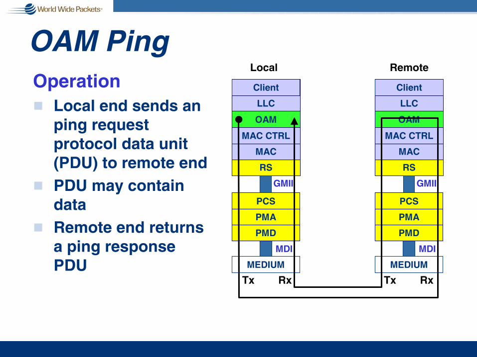
OAM PingOperationg Local end sends an
ping request protocol data unit (PDU) to remote end
g PDU may contain data
g Remote end returns a ping response PDU
PMD
PMA
PCS
MEDIUM
GMII
MDI
RS
MAC
MAC CTRL
LLC
Client
OAM
PMD
PMA
PCS
MEDIUM
GMII
MDI
RS
MAC
MAC CTRL
LLC
Client
OAM
Tx Rx Tx Rx
Local Remote

OAM Frame LoopbackOperationg Local end sends
loopback control PDU requesting remote end to go into loopback for a prescribed period of time
g Local ends sends arbitrary data frames
g Remote end returns data frames
Frame BER equals bit BER to high probability when bit BER is better than 10e-6
PMD
PMA
PCS
MEDIUM
GMII
MDI
RS
MAC
MAC CTRL
LLC
Client
OAM
PMD
PMA
PCS
MEDIUM
GMII
MDI
RS
MAC
MAC CTRL
LLC
Client
OAM
Tx Rx Tx Rx
Local Remote

Frame Errors vs. Bit Errorsg Assume errors are Poisson
distributed in timen e.g., system dominated by
white, Gaussian noisen ignores burst noise
g FER = BER if probability of >1 bit errors over the length of the frame is smalln depends on BER & frame
lengthn depends on acceptable
probability for FER ≠≠≠≠ BER
g Sample calculation:n 30kb framen acceptable probability ≤≤≤≤ 1%n ⇒⇒⇒⇒ BER ≤≤≤≤ 5 x 10 –6
Source: John Ewen, JDSU 2002
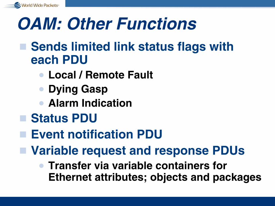
OAM: Other Functionsg Sends limited link status flags with
each PDUn Local / Remote Faultn Dying Gaspn Alarm Indication
g Status PDUg Event notification PDUg Variable request and response PDUs
n Transfer via variable containers for Ethernet attributes; objects and packages

Point-To-Point Overviewg 4 New Links (6 PMDs)
n Standardizes 100 Mbps 10km dual fibern Based on FDDI
n Standardizes 1 Gbps, 10km dual fibern Based on existing 10km parts available
n Adds 100 Mbps single fibern Based on TTC’s TS-1000 specification
n Adds 1 Gbps single fibern New
g No changes to PMA; PCS; or MACn Excepting simplex operation for OAM

Optical PMD Summary Sheet
-251480-15001270-1360->201-ONU-B
-291270-13601480-1500->201-OLT-B
-251480-15001270-1360->101-ONU-A
-261270-13601480-1500->1011000BASE-PX-OLT-A
-301480-16001260-1360->101-ONU
-301260-13601480-1580->101100BASE-BX-OLT
-251260-13601260-1360->102100BASE-LX
-201480-15001260-1360->101-BX-ONU
-201260-13601480-1500->1011000BASE-BX-OLT
-201260-13601260-1360>500>1021000BASE-EX
RxSen
(dBm)
λ λ λ λ Rx(nm)
λ λ λ λ Tx(nm)
MMF(m)
SMF(km)
# Fibers
Port Type

EFM Copper Introductiong Ethernet in the First Mile Copper (EFMC)
n Brings native Ethernet to the “First Mile” (ex. Last Mile) twisted-pair access network
g Why do we need it?n Existing Ethernet PHYs designed for engineered
wiringn Public access network originally designed for
voice-only, not datan FCC requirements for spectrum compatibility &
EMI not met by existing Ethernet PHYsn Existing DSLs optimized for non-Ethernet
protocols

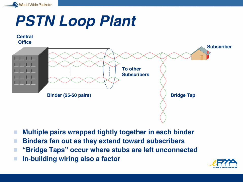
PSTN Loop Plant
g Multiple pairs wrapped tightly together in each binderg Binders fan out as they extend toward subscribersg “Bridge Taps” occur where stubs are left unconnectedg In-building wiring also a factor
CentralOffice
Subscriber
Bridge TapBinder (25-50 pairs)
To otherSubscribers
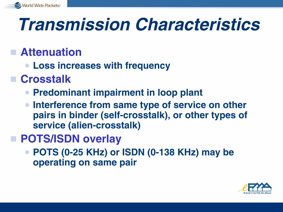
Transmission Characteristicsg Attenuation
n Loss increases with frequency
g Crosstalkn Predominant impairment in loop plantn Interference from same type of service on other
pairs in binder (self-crosstalk), or other types of service (alien-crosstalk)
g POTS/ISDN overlayn POTS (0-25 KHz) or ISDN (0-138 KHz) may be
operating on same pair

Band Plans for Different Services
g Band plan definitions administered by regulators to help endure operation of different services in same binder
PSD, dBm/Hz
Source: Cisco EFM Presentation

Near-End Crosstalk (NEXT)
Challenge: 50 twisted pair bundled into a single group and meeting band plans for DSL and VDSL

Crosstalk: FEXT and NEXT
g FEXT: Far-End X-Talkn Caused by transmitter operating on another pair in binder, at opposite
end from receivern Crosstalk level attenuated by loop attenuation
g NEXT: Near-End X-Talkn Caused by transmitter operating on another pair in binder, at same end
as receivern No loop attenuation; higher level than FEXT
g NEXT more problematic; commonly handled by using FDM to split upstream and downstream
“Remote” PHYs at subscriber end
Central Office PHYs
NEXT FEXT

Channel Capacityg Theoretical maximum bitrate depends on
available bandwidth, noise level
n C – theoretical bitrate capacityn s(f) – signal PSD, watts/Hz vs. freq.n N(f) – noise PSD at receivern H(f) – loop loss vs. freq.
g Channel capacity increases with bandwidth and signal PSD, decreases with loop loss, noisen Noise includes –174 dBm/Hz thermal noise & crosstalk
( ) ( )( )∫
×+= df
fN
fHfsC
2
2
1log

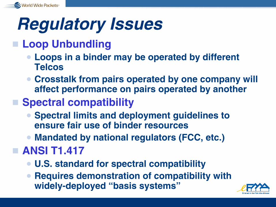
Regulatory Issuesg Loop Unbundling
n Loops in a binder may be operated by different Telcos
n Crosstalk from pairs operated by one company will affect performance on pairs operated by another
g Spectral compatibilityn Spectral limits and deployment guidelines to
ensure fair use of binder resourcesn Mandated by national regulators (FCC, etc.)
g ANSI T1.417n U.S. standard for spectral compatibilityn Requires demonstration of compatibility with
widely-deployed “basis systems”

Overview / Intro of DSL Technologies
g DSL – Digital Subscriber Linen Use of twisted-pair access loops for the
transmission of wideband digital signalsn Operates up to 12 MHz bandwidth (e.g., VDSL)
g Various DSLsn HDSL – symmetric, T1 carriage, no POTS overlayn ADSL – asymmetric, POTS overlay, medium-long
loopsn VDSL – symmetric & asymmetric, short loops,
high speed

EFM Copper:Based on DSL Technologies
g EFM copper PHYs use DSL modulation techniques
g Leverages years of work on DSL modulation development
g Ensures spectral compatibilityn And thus legality of deployment

DSL Modulation TechniquesTwo broad categories:g DMT – Discrete Multitone Modulation
n Large number of narrowband, orthogonal, modulated carriers
g QAM – Quadrature Amplitude Modulation
n Single wideband, modulated carrier
Both types commonly used in various DSL standards

EFMC: An Evolutionary Improvement over Existing DSLg EFM simplifies, specifies, mandates
interoperabilityn Simplified protocol layersn Reduces configuration, provisioning
optionsn IEEE 802.3 Ethernet tradition ensures
interoperabilityn Two Ethernet port types vs. a myriad of
non-interoperable DSL types

EFM Protocol Streamliningg Current typical
DSL protocol stack a byzantine collection
n Built to accommodate services that were never deployed
n Result is additional costs for needless provisioning, configuration, and maintenance
PMD
AAL5
Slow ATM path
PPP
Mux
Fast ATM path
UnusedUnused Eth
ernet
To PC To PC or or
gatewaygateway
Typical DSL ModemTypical DSL Modem

Protocol Streamlining (cont’d)
AAL5
Slow ATM path
PPP
Mux
Fast ATM path
UnusedUnused Eth
ernet
Typical IP connection begins and ends on Ethernetg Flexibility of ATM unutilized; complexity unnecessaryg New DSL systems will strip out intermediate sublayers,
move to native Ethernet on DSL
PMD
DSL DSL ModemModem
PHY PHYxTU-CSDH
ATM
SDH
AAL5
PPP
Ethernet
IP
Ethernet
IP
PCPC
RouterRouter
DSLAMDSLAM
FiberFiber Copper LoopCopper Loop Cat5Cat5
Ethernet
Ethernet
Ethernet

Work In Progress (cir 9/02)Ethernet First Mile Task Force Copper:g working to select line code for long
reach from between DMT and QAMn …“omahony_copper_1_0702.pdf” as the …“omahony_copper_1_0702.pdf” as the …“omahony_copper_1_0702.pdf” as the …“omahony_copper_1_0702.pdf” as the
basis for the line code evaluation criteria.basis for the line code evaluation criteria.basis for the line code evaluation criteria.basis for the line code evaluation criteria.n …limit proposals for consideration regarding …limit proposals for consideration regarding …limit proposals for consideration regarding …limit proposals for consideration regarding
the long reach objective to those based on the long reach objective to those based on the long reach objective to those based on the long reach objective to those based on “artman_copper_1_0702.pdf” and “artman_copper_1_0702.pdf” and “artman_copper_1_0702.pdf” and “artman_copper_1_0702.pdf” and “jackson_copper_1_0702.pdf”“jackson_copper_1_0702.pdf”“jackson_copper_1_0702.pdf”“jackson_copper_1_0702.pdf”

EPON Overview� Point-to-multipoint fiber network
� High bandwidth: 1 Gbps shared
� Low cost Ethernet + low cost fiber plant
� Minimizes use of fiber, CO feeders, and transceivers
� Passive optical infrastructure
� Fiber-to-the-home/building/business applications
� Suitable for voice, data, and video services

Optical First Mile
32 or 64 fibers64 transceivers
1 or 2 fibers66 transceivers
1 fiber33 transceivers
Example N=32 Nodes
passiveoptical splitter
curb switch
Point-to-Point Ethernet!!!! N or 2N fibers!!!! 2N optical transceivers
Curb Switched Ethernet!!!! 1 trunk fiber!!!! Minimum fiber/space in CO !!!! 2N+2 optical transceivers!!!! Electrical power in the field
Ethernet PON (EPON)!!!! 1 trunk fiber !!!! Minimum fibers/space in CO!!!! N+1 optical transceivers!!!! No electrical power in field!!!! Drop throughput up to trunk rate!!!! Downstream broadcast (video)
P2P
P2P
P2MP
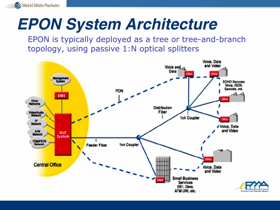
EPON System ArchitectureEPON is typically deployed as a tree or tree-and-branch topology, using passive 1:N optical splitters

Example: EPON Network
Photos courtesy of Alloptic, Inc.
EPON
The Optical Line Terminal(OLT) resides in the central office (PoP, local exchange). This is typically an Ethernet switch or media converter platform.
The Optical Network Terminal(ONT) resides at or near the customer premise. The ONT can be located on the curb/outside, in a building or at a subscriber residence. This unit typically has an 802.3ah WAN interface and an 802.3 subscriber interface.
1:N
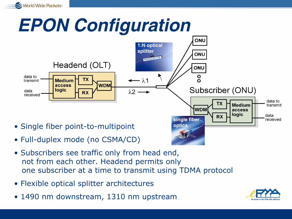
EPON Configuration
� Single fiber point-to-multipoint
� Full-duplex mode (no CSMA/CD)
� Subscribers see traffic only from head end,not from each other. Headend permits only one subscriber at a time to transmit using TDMA protocol
� Flexible optical splitter architectures
� 1490 nm downstream, 1310 nm upstream
1:N opticalsplitter
single fiberoptics

EPON in Ethernet Access Model
P2M PONT
P2PONT
P2PONT
P2MP and P2PSystem OLT +
Optical DistributionNetwork
DemarcationPoint
NetworkOperator
ServiceProviders
12
L3Service Multiplexing Switch
IPRouter
VoIPGW
VideoServer
SP1 SP2 SP3 SP4L3L2
Model 2
Model 1
IPRouter
VoIPGW
P2POLT
P2POLT
P2POLT
P2M POLT
L2 Bandwidth Concentration Switch
VideoServer
Ethernet PON can be deployed in an Ethernet access platform, with both point-to-point and point-to-multipoint access cards
Multipoint Control Protocol (MPCP)g EPON uses Multipoint Control Protocol (MPCP) to control
Point-to-Multipoint (P2MP) fiber networkg MPCP performs bandwidth assignment, bandwidth polling,
auto-discovery process and ranging, and is implemented in the MAC control layer
g New 64 byte MAC control messages are introduced. GATE and REPORT are used to assign and request bandwidth. REGISTER messages are used to control the auto-discovery process
g MPCP provides hooks for network resource optimization:n ranging is performed to reduce slackn reporting of bandwidth requirements by ONTs for DBAn optical parameters are negotiated to optimize performance
ONT and OLT OperationONT� Performs auto-discovery process which includes ranging,
assignment of logical link IDs, assignment of bandwidth
� Synchronizes to OLT timing through timestamps on the downstream GATE MAC control message
� Receives GATE message and transmits in permitted time period
OLT� Generates time stamped messages to be used as global
time reference
� Generates discovery windows for new ONTs, and controls registration process
� Assigns bandwidth and performs ranging

EPON Downstream
OLT ONU 2 USER 2
ONU 1
USER 3ONU 3
USER 1
1 3 1 2 1 3 1 2
13
12
13
12
1 1
2
3
header Payload FCS
802.3 frame
� Physical broadcast of 802.3 Frames
� 802.3 Frames extracted by logical link ID in preamble
� 64 byte GATE messages sent downstream to assign bandwidth

EPON Downstream: GATE Message
MAC Control Client
MAC Control
MAC
PHY
Clock register
Slot Start register
Slot Stop register
MAC Control Client
MAC Control
MAC
PHY
Generate GATEmessage
TimestampGATE message
Write registers
OLT ONU (1 of N)
Ups
t re a
mD
at a
Pat
h
Start
Stop
Start
Stop
TS
Start
Stop
TS
Laser ON/OFF
Clock register
MA_CONTROL.request(GATE) MA_CONTROL.indication(GATE) MA_DATA.request( … )
IN
SC
OP
E

EPON Upstream
OLT ONU 2 USER 2
ONU 1
USER 3ONU 3
USER 1
2
33 3
1 1
33
3
2
11
1 1 2 3 3 3
header Payload FCS
802.3 frame
time slot
� Upstream control managed by MPCP protocol
� Time slots contains multiple 802.3 Ethernet frames
� 64 byte REPORT Message sends ONU state to OLT
� No collisions
� No packet fragmentation

EPON Upstream: REPORT Message
MAC Control Client
MAC Control
MAC
PHY
Clock register
MAC Control Client
MAC Control
MAC
PHY
Generate REPORTmessage
Measure Round-Trip Time
OLT
TBD
TBD
TBD
TBD
TSClock register
MA_CONTROL.request(REPORT)MA_CONTROL.indication(REPORT)
IN
SC
OP
E
TimestampREPORT message
TBD
TBD
TS-RTT register
ONU (1 of N)

Round Trip Time (RTT) Measurement1. OLT sends
GATE at T1
2. ONU receives GATE and sets its clock to T1
3. ONU sends REPORT at T2
4. OLT receives REPORT at T3
5. OLT calculates RTT = T3 – T2
T1 ...
GATE
T2 ...
REPORT
GATE
T1 ...
REPORT
T2 ...OLT
Rx
Tx
ONURx
Tx
T1
T1
T2
T3
(T2-T1)
(T3-T1)
RTT = (T3-T1) � (T2-T1) = T3-T2** based on OLT clock; *** based on ONU clock
**
***
Work in Progress (cir 9/02)Ethernet First Mile Task Force P2MP:g Creating sublayers for P2MP that support
inherent downstream broadcast and P2P emulation
g Working to resolve architectural issues with the 802.3 layer stack
g Investigating possible support of L2 security
g Investigating possible use of forward error correction (FEC) to simplify P2MP optics
06/03/2002
Hybrid Fiber/Copper
• Next-generation, high-speed architectures–EFM copper for the last 700 to 800 meters–Minimum 10 Mbps – higher if possible–High bandwidth for entertainment – client/server–For stepwise buildout to work, EFMCu must support next-gen
applicationsP2P EFMF 1000 or 100 Mbps
P2MP EPON 32 Mbps per ONU
EFMCu – 10Mbps and up
Source: EFMA 2002

Bandwidth vs. Time
1.E+03
1.E+04
1.E+05
1.E+06
1.E+07
1.E+08
1.E+09
1.E+10
1.E+11
1980 1985 1990 1995 2000 2005
Ban
dw
idth
(b
aud
; b
oth
dir
ecti
on
s)
Ethernet (2000X in 12 yr)Modem (47X in 17 Yr)DSL (13X in 12.5 yr)
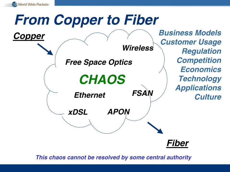
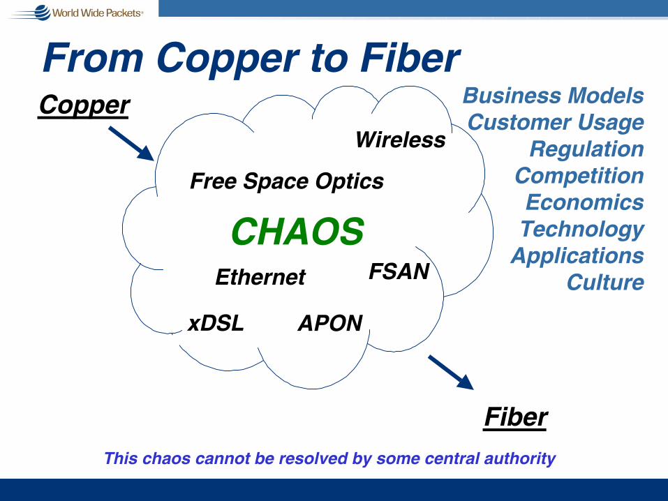
From Copper to Fiber
CHAOS
Business ModelsCustomer Usage
RegulationCompetitionEconomicsTechnology
ApplicationsCulture
Fiber
Wireless
xDSL
Free Space Optics
FSAN
APON
This chaos cannot be resolved by some central authority
Ethernet
Copper

IEEE 802.17aka Resilient Packet Ring
aka RPRaka ?Ethernet Loop?

RPR Overviewg Dual counter-rotating ring topologyg Frame-based transmission (jumbo support)g Defines a Layer 2 protocol
n Support for Unicast/Multicast/Broadcastn Familiar 48-bit MAC addresses
g Native support for QoSn 4 classes: Reserved, high, medium, lown Fair access to available (unreserved) capacity
g Fast fail-over (sub 50ms)g Dynamic topology discoveryg Use 802.3 and SONET PHY technology
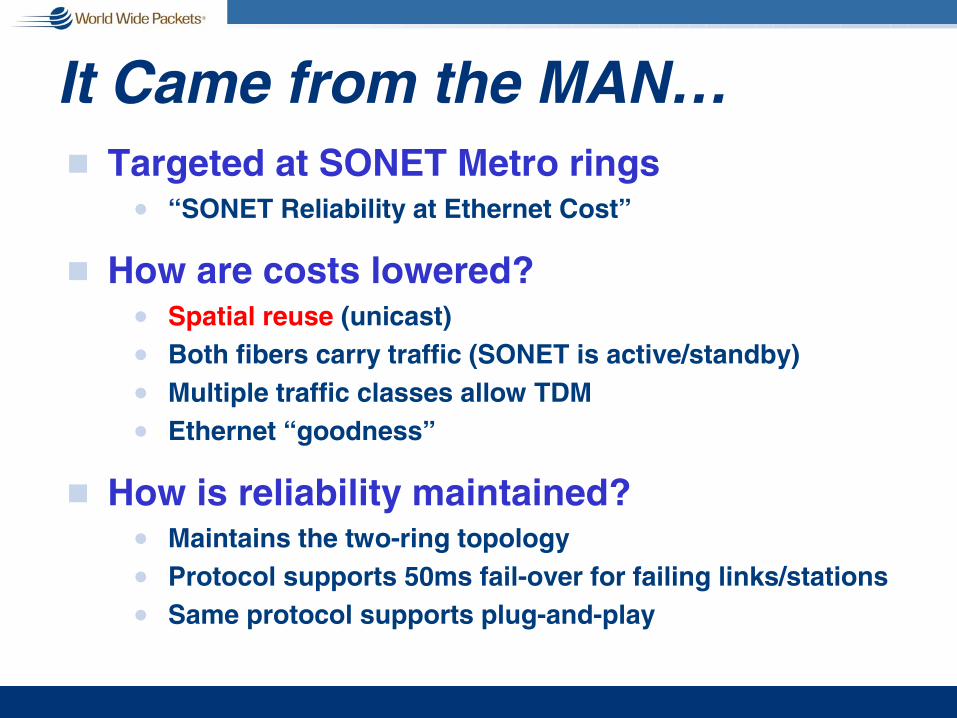
It Came from the MAN…g Targeted at SONET Metro rings
n “SONET Reliability at Ethernet Cost”
g How are costs lowered?n Spatial reuse (unicast)n Both fibers carry traffic (SONET is active/standby)n Multiple traffic classes allow TDMn Ethernet “goodness”
g How is reliability maintained?n Maintains the two-ring topologyn Protocol supports 50ms fail-over for failing links/stationsn Same protocol supports plug-and-play

RPR: A System ViewStation
Station
Station
Station
Station
Station
Outer Ringlet
Inner Ringlet
Span

An RPR Data Frame
RPR HEADER
DESTINATION MAC ADDRESS
SOURCE MAC ADDRESS
PROTOCOL TYPE FIELD (TBD)
PAYLOAD
2 Octets
6 Octets
6 Octets
2 Octets
m Octets
FCS4 Octets
7 6 5 4 3 2 1 0
TTL
MODE PRIRI IOP

RPR Header Fieldsg TTL(8 bits)
n Time To Liven Set to number of hops
to destinationn Decremented when
forwarded by noden Allows for 255 nodes
on ring
g MODE(3 bits) n Frame type
Data7
Fairness6
Control5
Protection Control4
Steering only data3
Reserved2
Reserved1
Reserved0
DescriptionMode Value

RPR Header Fields (cont.)g RI(1 bit) - Ringlet Identifier
n Origination ringlet
g IOP(1 bits) – In/Out Profilen Used for medium priority trafficn Out of profile traffic treated as low priority
Counterclockwise ringlet1
Clockwise ringlet0
DescriptionValue
In profile1
Out of profile0
DescriptionValue

RPR Header Fields (cont.)g PRI(3 bits) – Priority
g Entire 3-bit priority used by MAC clientn For transmit schedulingn For receive processing
Low priority0-6
High priority7
DescriptionValue

Overview of an RPR MAC
MAC Client
MAC Control Sublayer
DropLogic
Ringlet Input
MAC FairnessControl Unit
M
M
M
M
Policer/Shaper M : rate monitor
Ringlet Output
MFU ofmate
STOP_LP/MP/HP
Cntl
HP
LP/MP
add
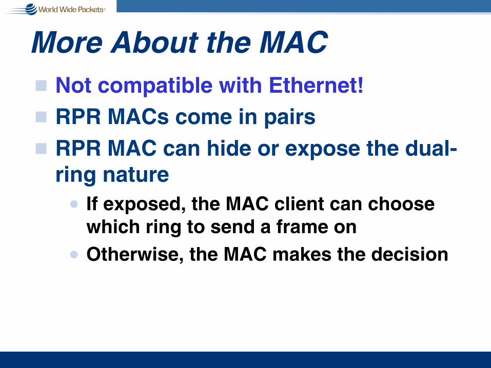
More About the MACg Not compatible with Ethernet!g RPR MACs come in pairsg RPR MAC can hide or expose the dual-
ring naturen If exposed, the MAC client can choose
which ring to send a frame onn Otherwise, the MAC makes the decision

RPR Traffic Classesg Reserved (A0)
n Guaranteed rate and tightly bounded delay/jitter
g High (A1)n Committed rate with controlled delay/jittern Subject to capacity restoration
g Medium (B)n Committed rate + burst capabilityn In profile/out of profile (excess MP)n eMP subject to RPR-FA (Fairness Algorithm)
g Low (C)n Best effortn Subject to RPR-FA

RPR Ring Accessg Forwarding
n 1 or 2 transit buffers (HP & LP/MP)
g Policingn Each node has maximum total add raten And an add rate for each traffic class (A,B,C)n Implemented with token bucketsn Communicate status back to MAC client
g Dynamic shapingn Nodes can make use of the excess or recovered
bandwidthn Utilizes the RPR-FA algorithm

Access Rules
LP TransitNearly Full?
Add HP/MP?P
Add MP/LP?PFA
HP TransitHas Frame?
LP TransitHas Frame?
Update FA
(Add_rate + forward_rate) >(max_rate – reserved_rate)
HP Transit
LP Transit
HP/MP Add
Trigger FlowControl
eMP/LP Add
LP Transit P
FA
: Policing Engine
: Fairness Algorithm

RPR Fairness (RPR-FA)g Defined at the MAC layer
n Supplemented by MAC client
g Uses source-based weighted fairnessn Divide the available bandwidth among nodesn Nodes may be weighted to get more or less than their “fair
share”
g Applies only to LP/eMP trafficg Goals
n Reclaim unused committed BWn Fast responsen High BW utilizationn Stabilityn Scalability
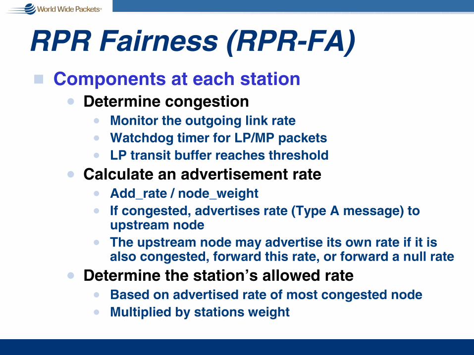
RPR Fairness (RPR-FA)g Components at each station
n Determine congestionn Monitor the outgoing link raten Watchdog timer for LP/MP packetsn LP transit buffer reaches threshold
n Calculate an advertisement raten Add_rate / node_weightn If congested, advertises rate (Type A message) to
upstream noden The upstream node may advertise its own rate if it is
also congested, forward this rate, or forward a null rate
n Determine the station’s allowed raten Based on advertised rate of most congested noden Multiplied by stations weight

Extended RPR Fairnessg Handled by MAC clientg Uses Type B fairness messages
n Broadcast to all nodesg Allows all choke points to be
simultaneously trackedn Leads to better spatial reusen Supports virtual destination queuesn Allows unlimited traffic for frames that are
in front of a choke pointn Requires only that each FA rule between
source and destination is obeyed

Ring Protectiong Wrapping vs. Steering
n This was a major sticking pointn The compromise was “Do Both”
g Steeringn Mandatory part of standardn “Steers” frames away from failed linksn Uses protection messages to advertise failuresn More frames may be dropped
g Wrappingn Optional in standardn All traffic is wrapped around when a station detects a
failure in its neighborn Fewer dropped frames

Steering Example – A to CStation
C
StationD
StationE
StationF
StationA
StationB
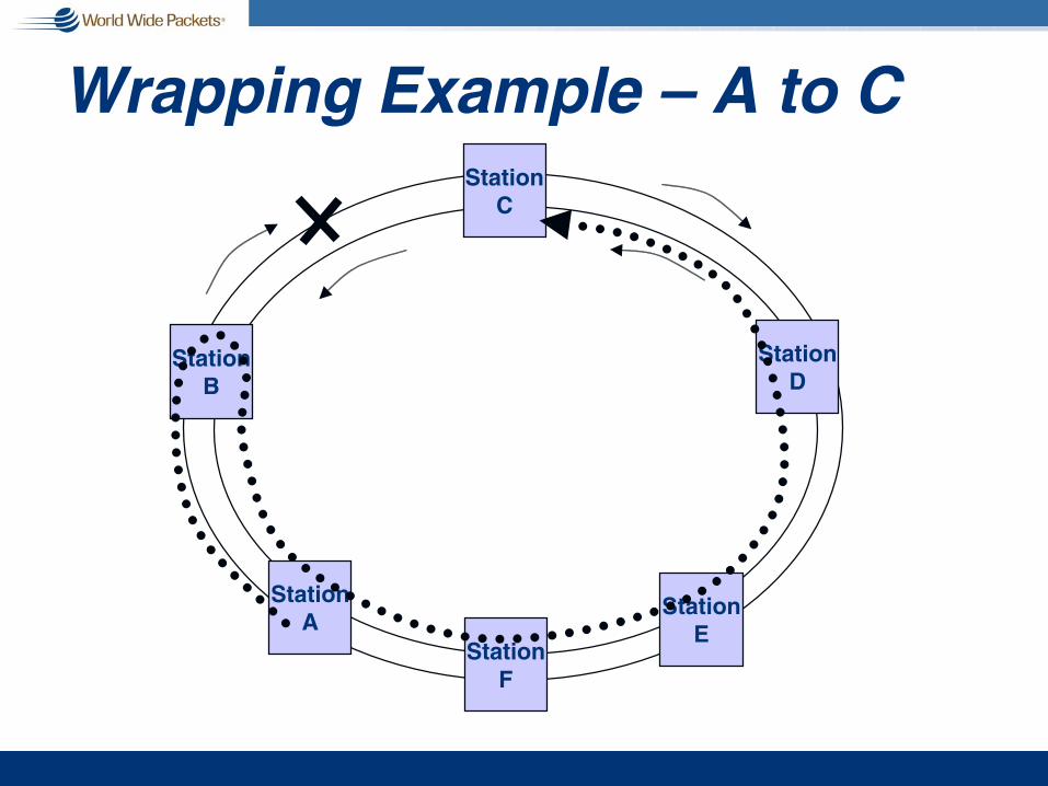
Wrapping Example – A to CStation
C
StationD
StationE
StationF
StationA
StationB

Physical Layerg There is no RPR PHY!g The standard defines reconciliation
layers for:n 1 Gig Ethernet – GMIIn 10 Gig Ethernet – XGMII, XAUIn SONET/SDH at 155Mbps to 10Gbps
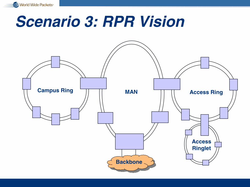
Scenario 3: RPR Vision
BackboneBackbone
MAN Access RingCampus Ring
AccessRinglet

RPR to SONET Comparison
!
!
!
!
!
!
!
RPR
High bandwidth efficiency on dual-ring topology
Cost-effective for data
Optimized for data
!50-millisecond ring protection
!Controlled latency and jitter
Full FCAPS* with LAN-like economics
Fair access to ring bandwidth
SONET
*fault-management, configuration, accounting, performance, and security
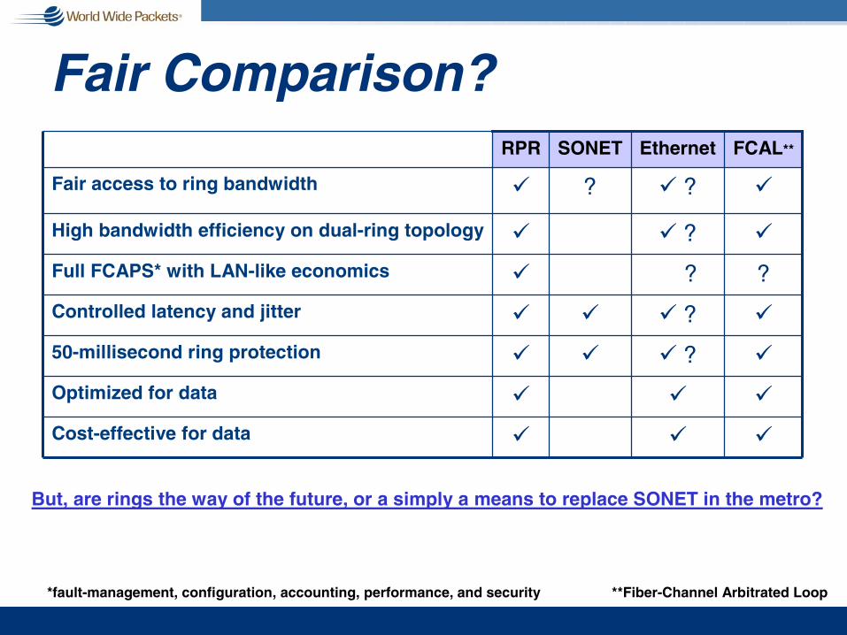
Fair Comparison?
!
!
!
!
!
!
!
RPR
!! ?High bandwidth efficiency on dual-ring topology
!!Cost-effective for data
!!Optimized for data
!! ?!50-millisecond ring protection
!! ?!Controlled latency and jitter
??Full FCAPS* with LAN-like economics
!! ??Fair access to ring bandwidth
FCAL**EthernetSONET
*fault-management, configuration, accounting, performance, and security **Fiber-Channel Arbitrated Loop
But, are rings the way of the future, or a simply a means to replace SONET in the metro?

RPR Conclusiong Frame based
g Supports a familiar topology to offer data services (SONET ring)
g Spatial Reuse n Like SSA and dual Ring FCn Unlike SONET
g Provides a layer-2 standard to address QoS and reliability
g Not Ethernet
But, does RPR offer sufficient benefit over Ethernet?
like Ethernet
�and Ethernet can�t?which Ethernet doesn�t need!
which Ethernet can do with much greater flexibility

Transceivers, Fibers, and Issues with Optics

OSI Layer Stack Mapping
Protocol
Coding
SERDES
XCVR
Media
Application
Presentation
Session
Transport
Network
Data Link
Physical
OSI Reference
Protocol
Coding
SERDES
XCVR
Media
DataFormat
N x 8 bit4 x 10 bit
1 bitSERDES
4 x 1 bit
4 x 8 bit
Proposed10 Gig Link
10 bit
1 bit 1 bit or4 x 1 bit or
Typical1 Gig Link
XAUI
XGMII
MDI
GMII
TBI
MDI
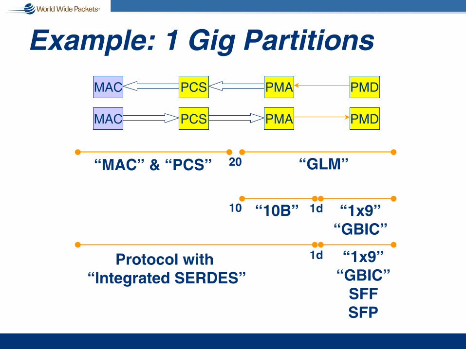
Example: 1 Gig Partitions
MAC PMAPCS PMD
“GLM”20
“10B” “1x9”“GBIC”
10 1d
“1x9”“GBIC”
SFFSFP
1d
MAC PMAPCS PMD
Protocol with “Integrated SERDES”
“MAC” & “PCS”

1GbE: Typical Implementation
Logical Link Control
Physical Medium Dependent
Physical Coding Sublayer
Physical Medium Attachment
MAC Control (Opt)
(XG)MII
Reconciliation Sublayer
Media Access Control
Media
802.3 Layer Model
MDI
circa ‘01circa ‘01
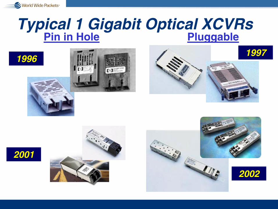
Typical 1 Gigabit Optical XCVRs
1x9 GBIC
SFF
SFP
Pin in Hole Pluggable
20012001
20022002
1997199719961996

Early 10 Gigabit Optical XCVRS
XGXS
XENPAK
FTRX
Seen at Optical Fiber Conference: • XENPACK; FTRX (300 pin MSA)• XXP; XPAK; XFP; SFP (@10 Gig!)

Multimode vs. Single Mode Cost
62.5 µµµµm
125 µµµµm
9 µµµµm
125 µµµµm
The vast majority of the cost difference is in the size of the target!
MultimodeFiber
Single modeFiber
Challenge: Control mechanical tolerances over temperature
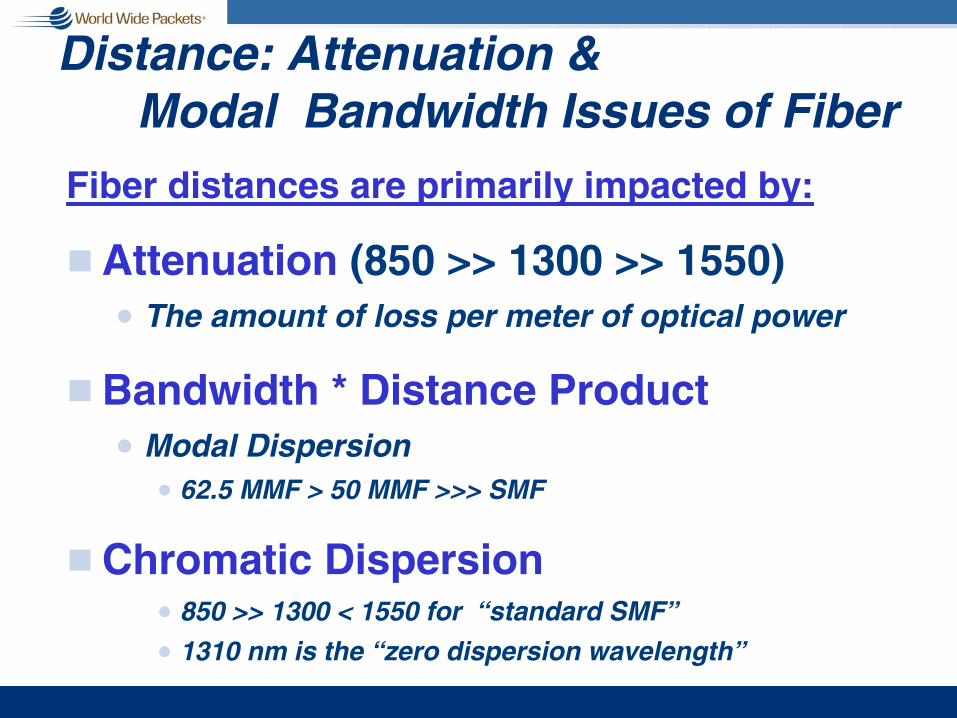
Distance: Attenuation & Modal Bandwidth Issues of Fiber
Fiber distances are primarily impacted by:
g Attenuation (850 >> 1300 >> 1550)n The amount of loss per meter of optical power
g Bandwidth * Distance Productn Modal Dispersion
n 62.5 MMF > 50 MMF >>> SMF
g Chromatic Dispersionn 850 >> 1300 < 1550 for “standard SMF”
n 1310 nm is the “zero dispersion wavelength”

Fiber Attenuation
600 800 1000 1200 1400 1600 1800
Wavelength in nanometers
Att
enua
tion
(lo
ss p
er m
eter
) Early 1970s
Mid 1970s
Early 1980s
More Loss
Less Loss

Effects of Dispersion
Optical power at fiber input
850 nm Oxide VCSEL @ 1.25 GBd
...and end of 600 m of 62.5 micron multimode fiber

Modal Dispersiong The net speed of light is a function of the path
(mode)n The smaller the core of the fiber, the fewer the number
of modes that will propagaten Single mode fiber (SMF) has only one mode and
therefore no modal dispersion (e.g., railroad)n Multi-mode fiber (MMF) “profiles” are doped so that all
paths take about the same time. Index at center of fiber “slows down” low order modes
Low order mode Higher order mode
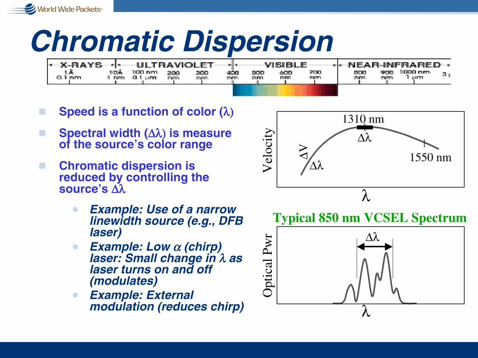
Chromatic Dispersion
g Speed is a function of color (λ)λ)λ)λ)
g Spectral width (∆λ)∆λ)∆λ)∆λ) is measure of the source’s color range
g Chromatic dispersion is reduced by controlling the source’s ∆λ ∆λ ∆λ ∆λ
n Example: Use of a narrow linewidth source (e.g., DFB laser)
n Example: Low αααα (chirp) laser: Small change in λλλλ as laser turns on and off (modulates)
n Example: External modulation (reduces chirp)
λ
Vel
ocity
∆λ
∆λ
∆Vλ
Opt
ical
Pw
r ∆λTypical 850 nm VCSEL Spectrum
1310 nm
1550 nm

802.3z New FCRx min (dBm) -19 -20Tx Min (dBm) -11 -9.5Budget (dB) 8 10.5Fiber A lloc . 2.5 5A ttn (dB/km) 0.5 0.5Dis tanc e (km) 5 10Rx /Tx max -3 -3Dy namic Rng 16 17
How Is 10 km Achieved When the 802.3z LW SMF Spec. Is 5 km?g Limit 1: Link budget =
Minimum optical power output - Minimum receive sensitivity
n A portion of the link budget is allocated to fiber loss (attenuation)
n Use simple photodiode
g Limit 2: Receiver Dynamic Range = Maximum - Minimum optical power into receiver
g 802.3z set objectives to achieve 3 km; some members objected to greater Rx dynamic range
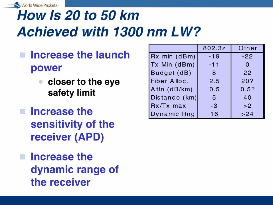
How Is 20 to 50 km Achieved with 1300 nm LW?
g Increase the launch power
n closer to the eye safety limit
g Increase the sensitivity of the receiver (APD)
g Increase the dynamic range of the receiver
802.3z OtherRx min (dBm) -19 -22Tx Min (dBm) -11 0Budget (dB) 8 22Fiber A lloc . 2.5 20?A ttn (dB/km) 0.5 0.5?Dis tanc e (km) 5 40Rx /Tx max -3 >2Dy namic Rng 16 >24

How Is 100 km Achieved with 1500 nm?
g Increase the launch power
n Eye safety virtually no problem at 1550 nm
g More Rx sensitivity
g More Rx dynamic range or engineer link to bound attenuation
g Control the ∆λ∆λ∆λ∆λ:
802.3z OtherRx min (dBm) -32Tx Min (dBm) 0Budget (dB) 32Fiber A lloc . 25?A ttn (dB/km) 0.25?Dis tanc e (km) 100Rx /Tx max >1Dy namic Rng >33
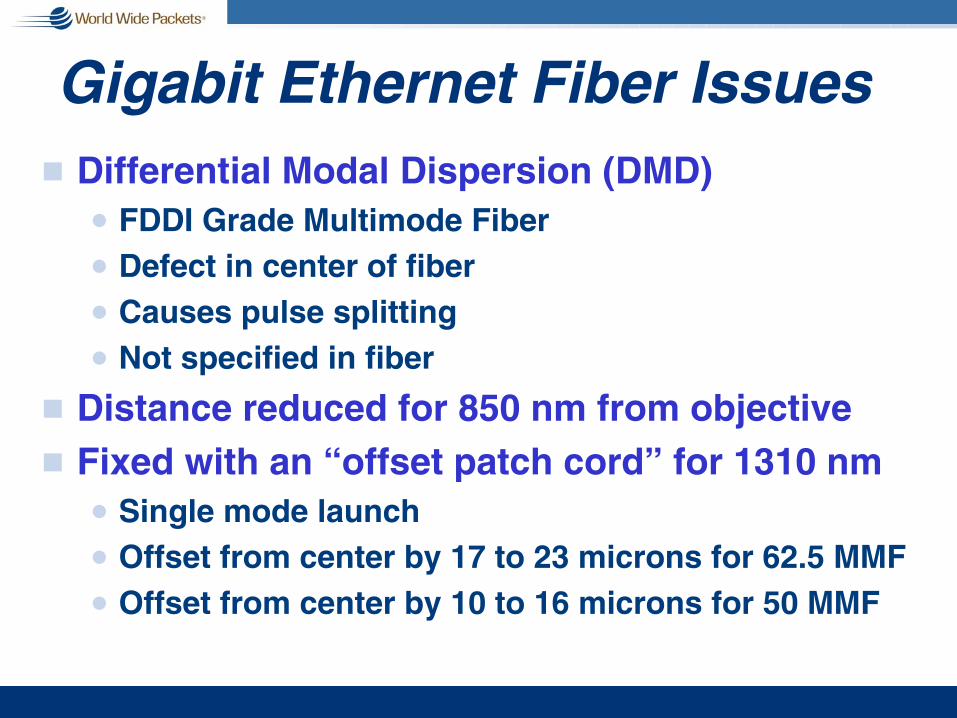
Gigabit Ethernet Fiber Issuesg Differential Modal Dispersion (DMD)
n FDDI Grade Multimode Fibern Defect in center of fiber n Causes pulse splittingn Not specified in fiber
g Distance reduced for 850 nm from objectiveg Fixed with an “offset patch cord” for 1310 nm
n Single mode launchn Offset from center by 17 to 23 microns for 62.5 MMFn Offset from center by 10 to 16 microns for 50 MMF
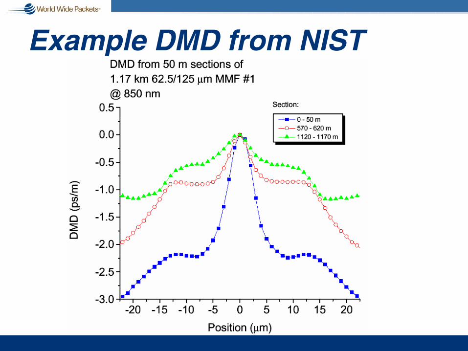
Example DMD from NIST
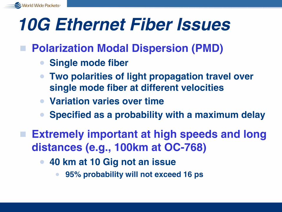
10G Ethernet Fiber Issuesg Polarization Modal Dispersion (PMD)
n Single mode fibern Two polarities of light propagation travel over
single mode fiber at different velocitiesn Variation varies over timen Specified as a probability with a maximum delay
g Extremely important at high speeds and long distances (e.g., 100km at OC-768)
n 40 km at 10 Gig not an issuen 95% probability will not exceed 16 ps

1 Gig Stressed Rx Eye Definition
Robust, difficult to create and validate

10 Gig Stressed Rx Eye Definition
Less robust; substantially easier to create and validate
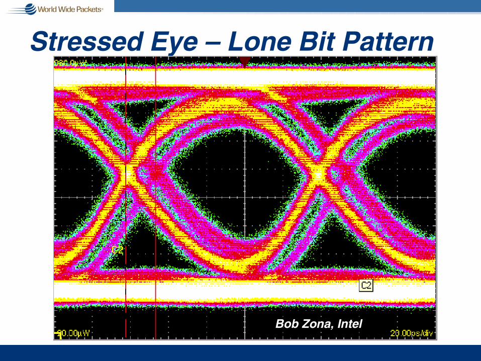
Stressed Eye – Lone Bit Pattern
Bob Zona, Intel
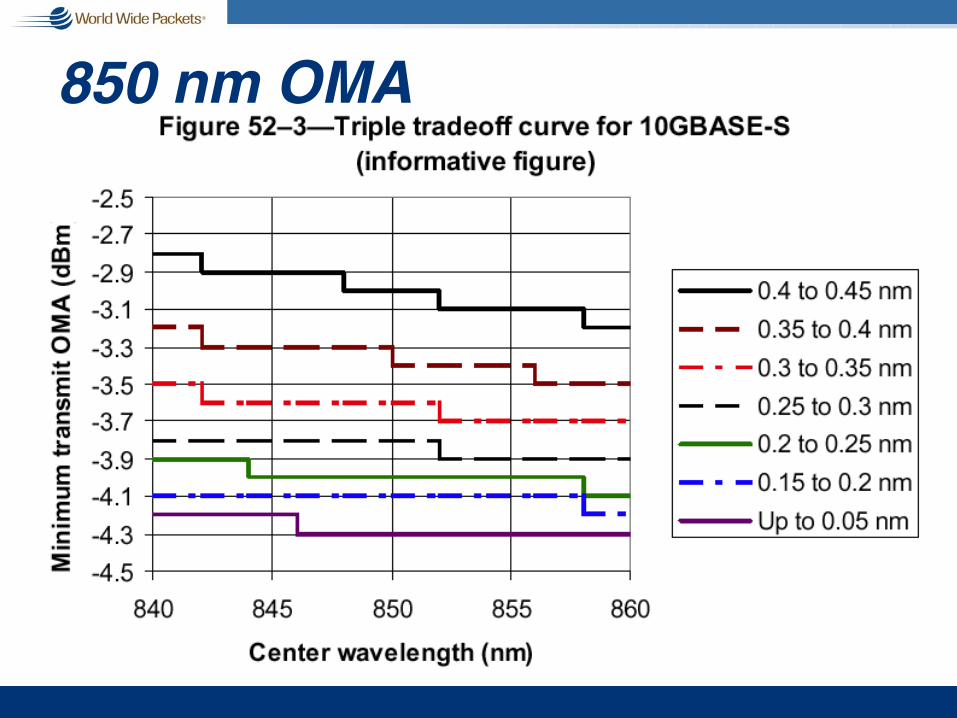
850 nm OMA

OMA vs. Optical Power (Sample)
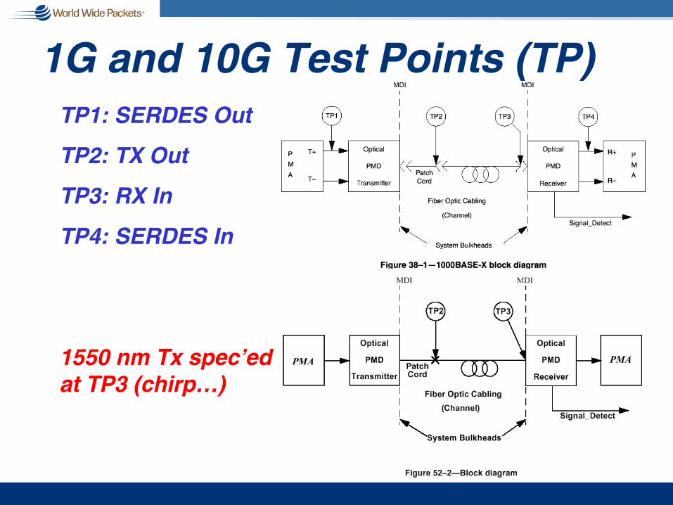
1G and 10G Test Points (TP)TP1: SERDES Out
TP2: TX Out
TP3: RX In
TP4: SERDES In
1550 nm Tx spec’ed at TP3 (chirp…)
10G Ethernet Optics Issuesg Pushing the low cost technology envelope
g Problems with test and measurementn Created “best of breed,” modern test
methodn BER jitter masks
n Test equipment was simply not good enoughn Yesterday’s “fat” is today’s specificationn Testing indicated high percentage of “false
negatives”
n Changed methodology for 10G Serialn Time and Dispersion Penalty (TDP)

10G Jitter Masks – Almost
This scheme is still used for
10GBASE-LX4
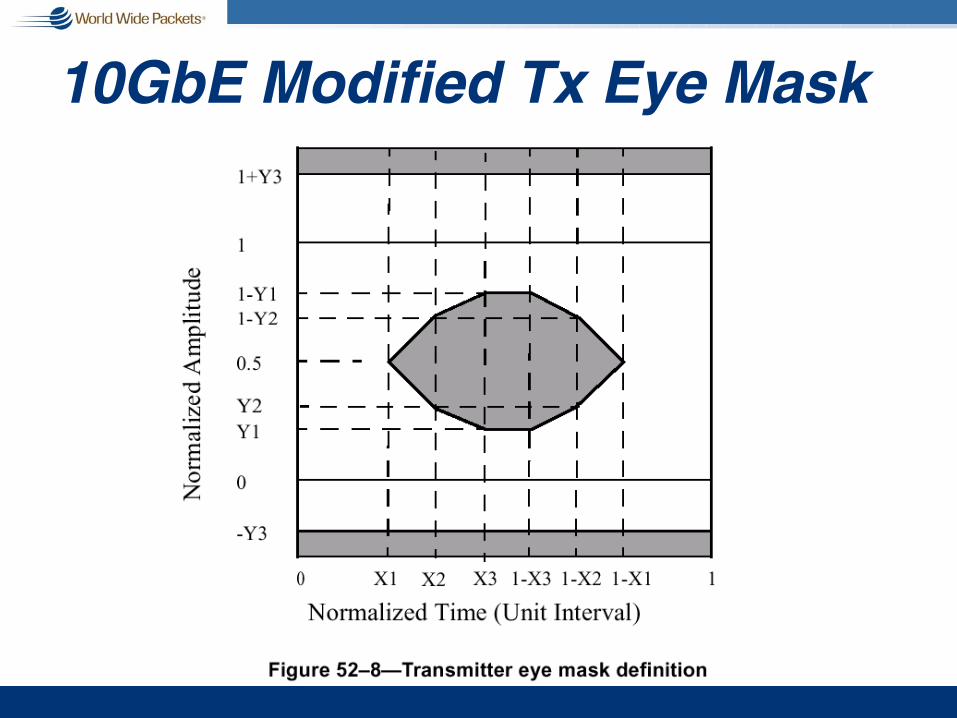
10GbE Modified Tx Eye Mask

Block Diagram for LX4 PMD
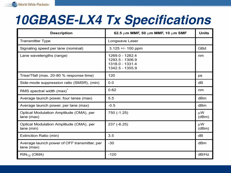
10GBASE-LX4 Tx Specifications
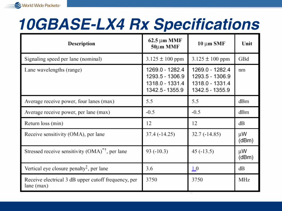
10GBASE-LX4 Rx Specifications

10GBASE-L Tx Specifications
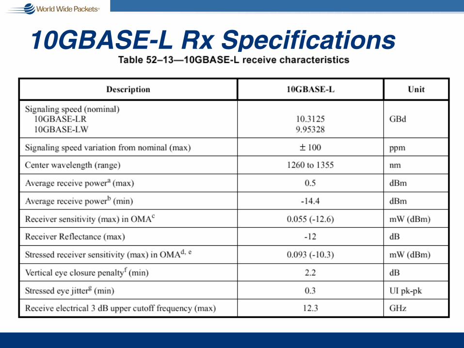
10GBASE-L Rx Specifications

The Challenge:Putting Down the Fiber

Fiber RecommendationsOutside the building? Install SMF
n Consider higher grade fiber if:n Longer distancesn Potential for upgrade to DWDM
Inside buildingn Jumpers? Don’t care; buy with equipmentn Vertical and horizontal
n Easy to re-pull? 2000 MHz*km MMF good to 10 Gign Expensive to re-pull? SMF or Hybrid SMF/MMFn Still not sure? Safe bet is SMF
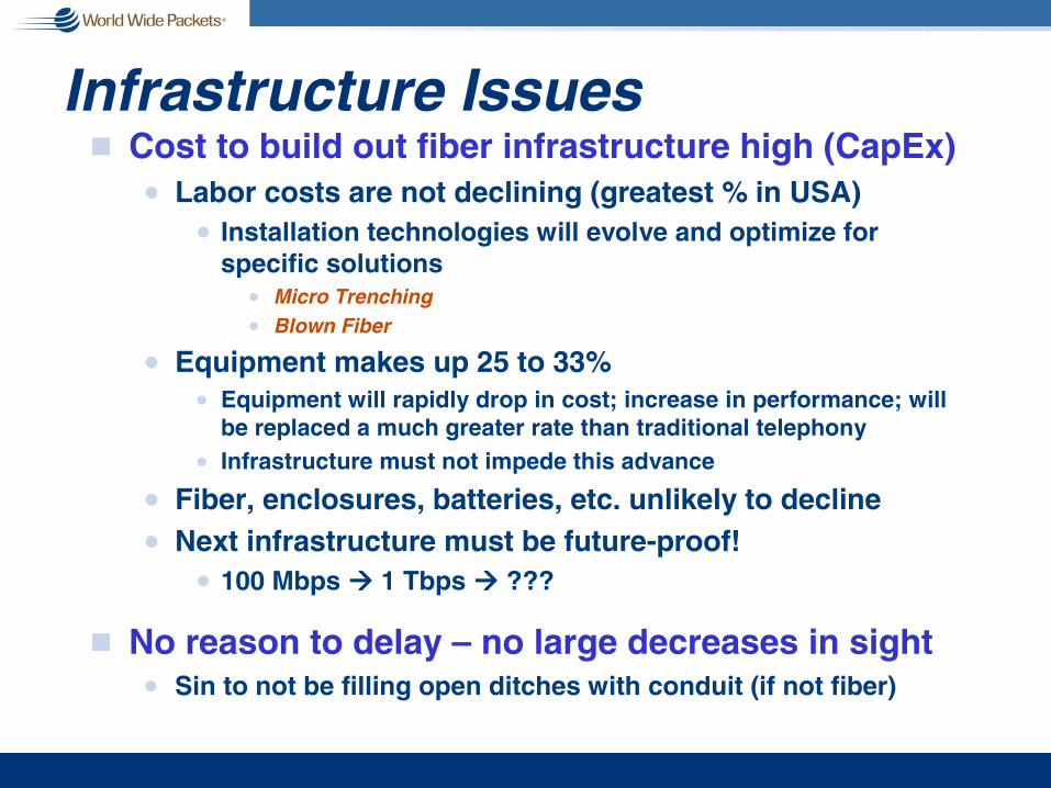
Infrastructure Issuesg Cost to build out fiber infrastructure high (CapEx)
n Labor costs are not declining (greatest % in USA)n Installation technologies will evolve and optimize for
specific solutionsn Micro Trenchingn Blown Fiber
n Equipment makes up 25 to 33%n Equipment will rapidly drop in cost; increase in performance; will
be replaced a much greater rate than traditional telephonyn Infrastructure must not impede this advance
n Fiber, enclosures, batteries, etc. unlikely to declinen Next infrastructure must be future-proof!
n 100 Mbps !!!! 1 Tbps !!!! ???
g No reason to delay – no large decreases in sightn Sin to not be filling open ditches with conduit (if not fiber)

6/18/02 WWP Community Networks 2002 6
Distribution Costs
Distribution of Hub Capital
7%8%
8%
2%
1%
19%
5%
0%
50%
0%
fiber to hub materials
fiber to hub labor
hub cabinet material
hub cabinet labor
hub splicing material
hub splicing labor
hub battery backupmaterial
hub battery backup labor
hub electronics material
Labor: 8+2+19 = 29%
6/18/02 WWP Community Networks 2002 7
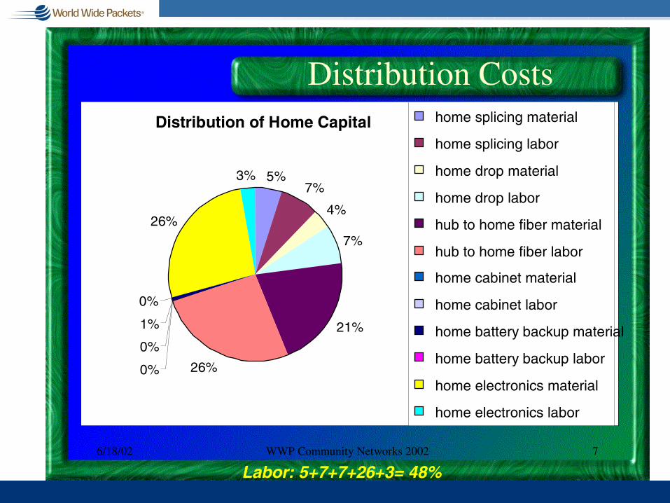
Distribution CostsDistribution of Home Capital
5%7%
4%
7%
21%
26%0%
0%
1%
0%
26%
3%
home splicing material
home splicing labor
home drop material
home drop labor
hub to home fiber material
hub to home fiber labor
home cabinet material
home cabinet labor
home battery backup material
home battery backup labor
home electronics material
home electronics labor
Labor: 5+7+7+26+3= 48%

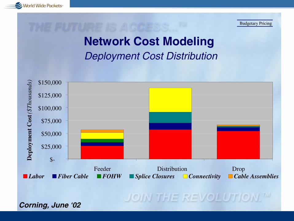
Network Cost ModelingDeployment Cost Distribution
Budgetary PricingBudgetary Pricing
Connectivity
Cable Assemblies
Labor
FOHW
Splice Closures
Fiber Cable
Corning, June ‘02
Network Cost ModelingDeployment Cost Distribution
Budgetary PricingBudgetary Pricing
$-
$25,000
$50,000
$75,000
$100,000
$125,000
$150,000
Feeder Distribution Drop
Dep
loym
ent
Cos
t ($T
housands)
Labor Fiber Cable FOHW Splice Closures Connectivity Cable Assemblies
Corning, June ‘02

TFSConfidential & Proprietary.
Traditional Fiber Builds
Street Cutting
Excavation

TFSConfidential & Proprietary.
Vault Placement
“Temporary” Restoration
Traditional Fiber Builds, con’t

TFSConfidential & Proprietary.
Micro-Trench
• Up to 4 Cables per Cut
• Low Intensity Construction
• Non-Destructive Installation
• Rapid Deployment• Improved Agency
Acceptance
TFSConfidential & Proprietary.
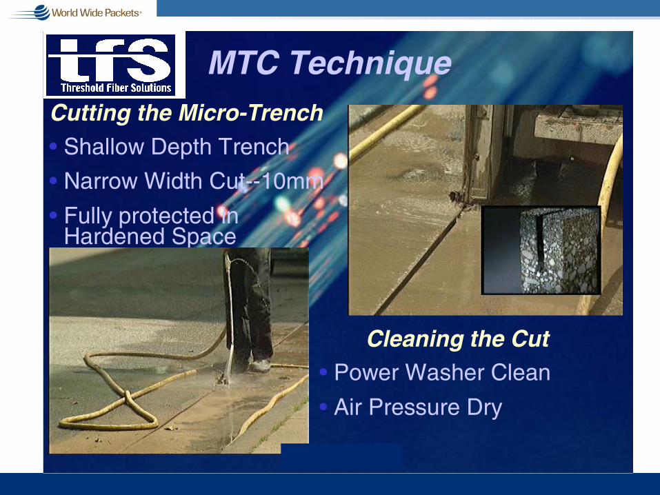
MTC Technique
• Shallow Depth Trench
• Narrow Width Cut--10mm
• Fully protected in Hardened Space
Cutting the Micro-Trench
• Power Washer Clean
• Air Pressure Dry
Cleaning the Cut

TFSConfidential & Proprietary.
Hold Strip and Thermal Seal
• ½” Polyfoam Hold down Rod
• 7/16” EPDM Sponge Rubber Thermal Seal

TFSConfidential & Proprietary.
MTC Technique (con’t)
• Low Impact to Traffic• Installed quickly• Flexible, Durable
Sealing the Cut
Hot Bitumen Sealant
Silica Grout Seal

TFSConfidential & Proprietary.
Why MTC?
Micro Trench Construction (MTC)
What is MTC?• Shallow Depth Trench
• Fiber Payload Encased in Fully in Protected, Hardened Space
• Can Deploy more than 1,000 feet per day per crew
•Traditional “Carrier Class” Depth Cost Prohibitive to Address Last Mile Development
•Other Alternatives (Sewer/Gas lines) Too Complex for Wide Adoption
•Match Solution to Application

TFSConfidential & Proprietary.
TrenchingRobotics
DirectionalBoring
MTC
MTC Less Than All Other Options
Illustrative Example of Build Costs

TFSConfidential & Proprietary.
• Fastest Fiber Deployment/Delivery Method Available Permitting Through Construction
• Delivers Access and Point-to-Point Fiber Solutions
• Delivers Fiber At Wire Line Prices
• Minimal Disruption To Pedestrian and Traffic Flow
• Survivable and Diverse Entry Topologies
• Very Rapid Repair and/or Restoration
MTC Advantages

Blown Fiber Microconduit

AA -- The ConceptThe Concept• The Fibreflow system itself consists of dedicated channels of micro-tubes
enclosed in a protective jacket designed to suit a range of environments both indoors and outdoors.
• Fibre unit bundles are then blown down the tubes on demand.
• When your customers ask for a connection, small optical fibre units are blown into the micro-tubes, without the need to splice.
• Branching can be done anywhere along the route by cutting into the protective jacket and connecting the existing micro-tube to a branch micro-tube using a permanent or push/pull connector.
• The Fibreflow solution can provide fibre optic links all along the network on a “Just in time” basis
• Fibreflow can be laid: within existing telecommunications ducting, withinother utilities connections, as direct bury or over head.
Emtelle, June 2002

Sales GenerationSales Generation• Why gamble on Dark Fibre?• Saleable capacity with no more street digs • Innovative solution capable of winning new contracts• Numerous order winning features and benefits• Back up support to deliver cutting edge solutions• Assists utilisation of unemployed fibre in legacy networks• Access customer with greater ease• Ease of response to changing customer demands• Point to Point Fibre product offering• Dedicated fibre path offering• Fibre can be upgraded with minimum customer interruption
Emtelle, June 2002
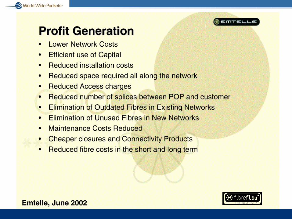
Profit GenerationProfit Generation• Lower Network Costs• Efficient use of Capital• Reduced installation costs• Reduced space required all along the network• Reduced Access charges• Reduced number of splices between POP and customer• Elimination of Outdated Fibres in Existing Networks• Elimination of Unused Fibres in New Networks• Maintenance Costs Reduced• Cheaper closures and Connectivity Products• Reduced fibre costs in the short and long term
Emtelle, June 2002

AA SavingsSavings
Traditional
Fibreflow
0
200,000
400,000
600,000
800,000
1,000,000
1,200,000
Fibre SplicesFibreTrench
Emtelle, June 2002

Trends and Influences
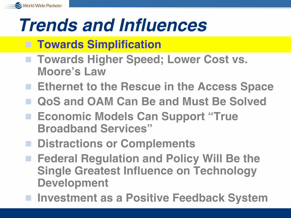
Trends and Influencesg Towards Simplificationg Towards Higher Speed; Lower Cost vs.
Moore’s Lawg Ethernet to the Rescue in the Access Spaceg QoS and OAM Can Be and Must Be Solvedg Economic Models Can Support “True
Broadband Services”g Distractions or Complementsg Federal Regulation and Policy Will Be the
Single Greatest Influence on Technology Development
g Investment as a Positive Feedback System

The Pythagorean Paradigmn The planets, sun, moon, and
stars move in perfectly circular orbits;
n The speed of the planets, sun, moon, and stars in their circular orbits is perfectly uniform;
n The Earth is at the exact center of the motion of the celestial bodies

Plato’s Homework ProblemPlato gave his students a major
problem to work on. Their task was to find a geometric explanation for the apparent motion of the planets, especially the strange retrograde motion
One key observation: As a planet undergoes retrograde motion (drifts westward with respect to the stars), it becomes brighter

Ptolemaic System

Problem Solved Mathematically

Ptolmy’s Epicycles

And then….
Portrait of CopernicusBefore 1584 AD - Tobias Stimmer
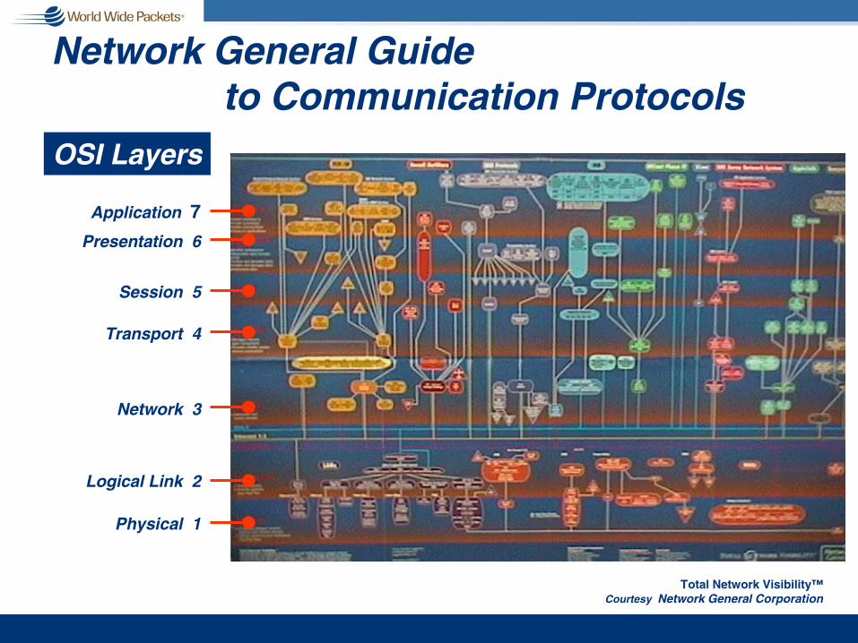
Network General Guide to Communication Protocols
Total Network Visibility™Courtesy Network General Corporation
OSI Layers
Application 7
Presentation 6
Session 5
Transport 4
Network 3
Logical Link 2
Physical 1

Complexity Resolved
Ethernet
Token Bus
Token Ring
FDDIDQDB ATM
ISDN
Frame Relay
Modems
PPPSMDSSONET
Layer 2Logical Link

Complexity Resolved (again)
DLSw
IP
IPX
COFPDRP
IDP
DDP
Layer 3Network
VIP
CLNP

Convergence == Simplicity
Resolving Network Complexityfrom the Bottom Up
Application 7Presentation 6
Session 5
Transport 4
Network 3
Logical Link 2
Physical 1

Teenagers Set Up Networks for FUN
100 Mb/s Ethernet network set up for evening of gaming

ALAN / MAN / RAN / WANg In the future,
network market segments will not be defined strictly by geography

Ethernet ‘Trucks’
PacketPacket
PacketPacket
Packet Packet
PacketPacket
Packet PacketPacket Packet
Packet Packet
Packet Packet
PacketPacket

SONET ‘Ferry’
Packet
Packet Packet Packet
PacketPacketPacketPacket
Packet Packet Packet Packet
Packet
Packet
Packet
Packet
Packet
PacketPacket
Packet Packet
Packet Packet Packet
Packet Packet Packet Packet
Packet
PacketPacket
PacketPacket
Packet
Packet
The Legacy Network
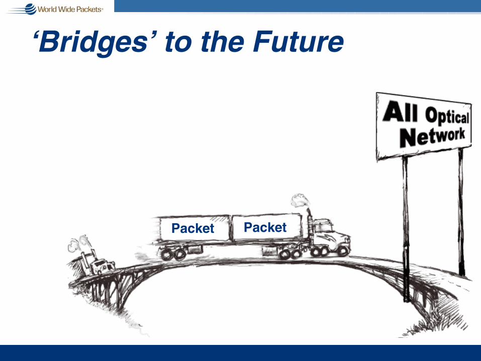
‘Bridges’ to the Future
PacketPacket

Just a Bridge Too Far…
Packet
Packet Packet Packet
PacketPacketPacketPacket
Packet Packet Packet Packet
Packet
Packet
Packet
Packet
Packet
PacketPacket
Packet Packet
Packet Packet Packet
Packet Packet Packet Packet
Packet
PacketPacket
PacketPacket
Packet
Packet
From Copper to Fiber
CHAOS
Business ModelsCustomer Usage
RegulationCompetitionEconomicsTechnology
ApplicationsCulture
Fiber
Wireless
xDSL
Free Space Optics
FSAN
APON
This chaos cannot be resolved by some central authority
Ethernet
Copper

The Interconnect Dilemma:
Processor Bus Local I/O Bus(inter chip)
Back plane Storage/System Area Network
Local Area Network
MAN/WAN
RapidIO
PCI
LDT
FSB HL-1&2
Ethernet
ATM
SONET
CSIX
SP
SP-2
Proprietary Licensable Open Standard
InfiniBand
Fibre Channel
Other Proprietary
3GIO
Too Many Alternatives!Too Many Alternatives! Source: Intel, 2001

Trends and Influencesg Towards Simplificationg Towards Higher Speed; Lower Cost vs.
Moore’s Lawg Ethernet to the Rescue in the Access Spaceg QoS and OAM Can Be and Must Be Solvedg Economic Models Can Support “True
Broadband Services”g Distractions or Complementsg Federal Regulation and Policy Will Be the
Single Greatest Influence on Technology Development
g Investment as a Positive Feedback System

Towards Moore’s LawAt 10Gig – We are definitely pushing the limit
of “low cost” technology doing full speed serial implementationsn Optical: Relatively easy for 100 & 1000
n Borrowed 100 from FDDIn Borrowed 1000 from Fibre Channeln Created “our own” for 10 Gig
n Copper: Pushing the limit at 1000n Test and measurement not keeping up
But – WDM will likely provide ability to meet or exceed requirements for several number of years

10 to 1 Gig Price-Performance
Usual inflection point and objective for economic feasibility is 3 – 4 : 1 for a 10X speed upgrade
Basis (Supercom ’02)RatioComponent
10GBASE-LR : 1000BASE-LX1000BASE-LX (seemed unreasonably high)
10 : 1NIC
Single SERDES; (1 Gig Quad/Octal/Integrated SERDES much greater ratio)
40 : 1SERDES
10GBASE-LR : 1000BASE-LX20 to 30 : 1Optics
10GBASE-LR : 1000BASE-LX40 : 1System
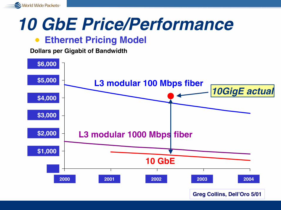
$0
$1,000
$2,000
$3,000
$4,000
$5,000
$6,000
2000 2001 2002 2003 2004
10 GbE Price/Performance Dollars per Gigabit of Bandwidth
L3 modular 100 Mbps fiber
L3 modular 1000 Mbps fiber
10 GbE
Greg Collins, Dell’Oro 5/01
$6,000
$5,000
$4,000
$3,000
$2,000
$1,000
2000 2001 2002 2003 2004
!!!!10GigE actual
n Ethernet Pricing Model

10 GbE Price/Performance
OC-3 (155 Mbps)
OC-12 (622 Mbps)
OC-48 (2.5 Gbps)
10 GbE$0
$10,000
$20,000
$30,000
$40,000
$50,000
2000 2001 2002 2003 2004
n SONET/SDH Pricing ModelDollars Per Gigabit of Bandwidth
$50,000
$40,000
$30,000
$20,000
$10,000
2000 2001 2002 2003 2004
OCOC--192 (10 Gbps)192 (10 Gbps)
Greg Collins, Dell’Oro 5/01
!!!!
10GigE actual

1 Gig E Technology DirectionsHigh Speed Serial
n Early: BiCMOS; BiPolar; GaAsn Mature: CMOS
Opticaln Early: 850 nm CD Lasers; 1310 nm FP Lasersn Mature: 850 nm VCSEL Lasers; 1310 nm FP Lasers
(1310 nm VCSELs soon?)
Packagesn Early: OLM n Mature: SFP; Integrated MAC/PHY/SERDES
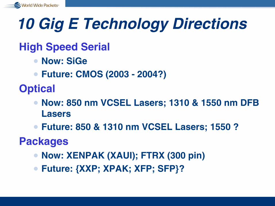
10 Gig E Technology DirectionsHigh Speed Serial
n Now: SiGen Future: CMOS (2003 - 2004?)
Opticaln Now: 850 nm VCSEL Lasers; 1310 & 1550 nm DFB
Lasersn Future: 850 & 1310 nm VCSEL Lasers; 1550 ?
Packagesn Now: XENPAK (XAUI); FTRX (300 pin)n Future: {XXP; XPAK; XFP; SFP}?

1 & 10 Gig Availability vs. Standard
MAR
MAY
JULY
SEPT
JAN
MAR
MAY
JULY
SEPT
NOV
JAN
MAR
MAY
JULY
SEPT
NOV
JAN
1999 2000 2001
HSSGFORMED
TaskForce
FormedSTD!WG
Ballot
TF Review
MAR
PAR Approved
}
Dra
ft 1
Dra
ft 2
Dra
ft 3
Dra
ft 1
.1
Dra
ft 2
.1
Dra
ft 4
Dra
ft 5
Dra
ft 3
.1
Dra
ft 3
.2
Dra
ft 3
.3
LMSC Ballot
Dra
ft 4
.1
Dra
ft 4
.2D
raft
4.3
NOV
MAY
JULY
2002
Preliminary Preliminary 1 Gig Optics 1 Gig Optics
AvailableAvailable
Preliminary 10 Gig Optics
Available
1 Gig 1 Gig InteroperabilityInteroperability
10 Gig Interoperability

40 Gig Next?
2006
2002
1998
1995
1990198310
100
1000
10000
100000
1980 1985 1990 1995 2000 2005 2010
Meg
abits
per
sec
ond
10BASE-T
Fast Ethernet
Gigabit Ethernet
10 Gigabit Ethernet
10BASE-T
Fast Ethernet
Gigabit Ethernet
10 Gigabit Ethernet
Moore
’s L
aw

100 Gig Next?2 00 6
2 00 2
1 99 8
1 99 5
1 99 01 98 310
100
1000
10000
100000
1980 1985 1990 1995 2000 2005 2010
Meg
abits
per
sec
ond
10BASE-T
Fast Ethernet
Gigabit Ethernet
10 Gigabit Ethernet
10BASE-T
Fast Ethernet
Gigabit Ethernet
10 Gigabit Ethernet
Moore
’sLaw

Reasons for 40g It would be a whole lot easier than 100
n Not as technically aggressive as Moore’s lawn 10 Gig was nearly torture; it would be nice to
have a break
g We have multiple ways to do itn 4 lambdas at 10 Gig each with 802.3ad link
aggregationn SONET Style OC-768
g Many SONET people believe Ethernet and SONET should walk together into the sunset….

Reasons for 100g Economics limiting R&D investment
n Current economy delaying uptake of 10n More time required for essential research
g Longer cycle (inter-speed) provides opportunity for cost reduction cycles
n Reduces overlap in concurrent design projects
n Improves ROI on principal technology investment
g Longer cycles encourage competition

Desktop Power Today vs. YesterdayDesktop Power Today vs. Yesterday
Gigabit bandwidth is needed to balanceGigabit bandwidth is needed to balanceIntelIntel®® PentiumPentium®® 4 Processor Performance4 Processor Performance
Bits per Hertz Ratio Bits per Hertz Ratio vs. vs.
Processor SpeedProcessor Speed
0.000.00
0.100.10
0.200.20
0.300.30
0.400.40
0.500.50
0.600.60
0.700.70
0.800.80
0.900.90
1.001.00
19911991 19931993 19951995 19971997 19991999 20012001 20032003 20052005 20072007
00
1G1G
2G2G
3G3G
4G4G
5G5G
6G6G
7G7G
8G8G
10Mbit10Mbit
HzHz
Bits perBits perHertzHertz
100Mbit100Mbit GigabitGigabit
Source: Intel Corp., 2002Source: Intel Corp., 2002 1111

Optical Backplane
Copper BackplaneCopper Serial Bus
10G Short Distance InterconnectsInter-Chip
Chip-to-Chip/Card Inter-CabinetRack-to-RackBox-to-Box
Inter-Facility, Enterprise,Site-to-Site, VSR,
Data Center-to-Data Center
Standard Optical
Inter-BoardBlade-to-BladeIntra-Cabinet
0” 20” 15 m 30 m 300 m
Source: Intel

I/O Architecture Evolution
Signaling Rate GHz
15
10
5
1
80s80s 90s90s 00s00s
ISAISA
8.33 MHz PCIPCI
UP TO 66 MHz
VESAVESAVLVL
EISAEISA
MCAMCA
OpticalOpticalInterconnectsInterconnects
PCIxPCIxUP TO 800 MHz HTHTHLHL
R I/OR I/O
AGPxAGPx
1GHz Parallel Bus Limit1GHz Parallel Bus Limit
>12 GHz Copper Signaling Limits>12 GHz Copper Signaling Limits
Third GenerationThird GenerationI/O ArchitectureI/O Architecture
• Full Serial
• Point-to-point
• Max Bandwidth/Pin
•Scalable >10 GHz
•Flexibility
•Multiple market segment
Source: Intel

OK, But What Speed’s Next?g Too early to tell
g Highly likely that IEEE 802.3 will wait until:
n Recovery of the marketn 10 Gig is available at better price-
performancen Lessons from 10 GbE not yet known
n Ethernet in the First Mile (802.3ah) is complete (or nearly complete)n EFM will drive demand for 10G and higher in
the backbone and core

Trends and Influencesg Towards Simplificationg Towards Higher Speed; Lower Cost vs.
Moore’s Lawg Ethernet to the Rescue in the Access Spaceg QoS and OAM Can Be and Must Be Solvedg Economic Models Can Support “True
Broadband Services”g Distractions or Complementsg Federal Regulation and Policy Will Be the
Single Greatest Influence on Technology Development
g Investment as a Positive Feedback System

Ethernet in the Access Space
Did I mentionEthernet in the First Mile?
☺☺☺☺What were people thinking when
they built out the WAN without EFM?

Backbone Glut or Access Dearth?

Emerging End-to-End Ethernet
Access to the Optically Fibered World“First Mile / Last Mile” 56 kbps →→→→ 1Gbps
Backbone Continent-to-Continent Coast-to-Coast all over Fiber at 10 Gbps & up
Metro City-to-City – Town-to-Townall over Fiber at 1Gbps →→→→ 10 Gbps
LAN Desktop-to-Desktop – Floor-to-Floor10 Mbps →→→→ 1Gbps
Integrated Services Video – Voice – Data
New World Order

Optical Ethernet Capabilities: Long Reach
1000BaseCXCopper
1000BaseT(802.3ab)
25m65m
100m
10GbE(802.3ae)
220m 275m 300m 500m 5km 10km 40km550m
SR/SW 850nm Serial (26 – 300m); 62.5 MMF up to 33m, 50 MMF up to 300m
4 Pr Cat5 UTP
1000BaseSX850nm 62.5 MMF 160 MHz-km Modal BW
62.5 MMF 200 MHz-km Modal BW1000BaseSX850nm
10GbE(802.3ae)
LX4 1310nm WWDM; 300m on 62.5 MMF, 500 MHz*km; LAN PHY only
1000BaseSX850nm
1000BaseSX850nm
50 MMF 400 MHz-km Modal BW
50 MMF 500 MHz-km Modal BW
1000BaseLX1300nm 50 or 62.5 MMF, 400 or 500 MHz-km Modal BW
1000BaseLX1300nm 9 SMF
10GbE(802.3ae)
LR/LW 1310nm Serial, SMF
10GbE(802.3ae)
ER/EW 1550nm Serial, SMF
Balanced Copper
10GbE(802.3ae)
LX4 1310nm WWDM; LAN PHY
Source: Luke Maki, Boeing Corporation, 2002

Trends and Influencesg Towards Simplificationg Towards Higher Speed; Lower Cost vs.
Moore’s Lawg Ethernet to the Rescue in the Access Spaceg QoS and OAM Can Be and Must Be Solvedg Economic Models Can Support “True
Broadband Services”g Distractions or Complementsg Federal Regulation and Policy Will Be the
Single Greatest Influence on Technology Development
g Investment as a Positive Feedback System
Page - 9© 2002 IP Services - All Rights Reserved
WWW.TCPIPSERVICES.COM
HAVE YOU CONSIDERED THE SERVICESYOUR NOC WILL PROVIDE?
• Monitoring –Core & Distribution Networks• Call Center• Change Management• Technical Team Support• Knowledge Base• Capacity Planning • Security• Customer Care• Contingency Planning• Asset Management / Control / Configuration• Trouble-Ticketing• Expedient Problem Escalation and Resolution

Other Key Management IssuesService and Design Release Resolution Supplier ManagementControl Cost Savings and
Containment Security ManagementAvailability and Contingency
Mgmt.Service Level ManagementService ReportingCapacity ManagementTesting of New TechnologyDesign of Change and
Release Timelines
Risk AssessmentRollback and Contingency Mgmt.Plans for Actual Release Roll-outsIncident ManagementEscalation ManagementProblem ManagementSLA (Service Level Agreement)
ManagementOLA (Operation Level Agreement)
ManagementReporting on Actual Performance
vs. Contract TermsAsset and Configuration Mgmt.Change ManagementMonitor and Maintain Configuration
Baselines
Source: Scott Alldridge – CEO, IP Services, June 2002 -- Reformatted

0018-02 3
What Is an OSS/BSS(Operational and Business Support System)What Is an OSS/BSS(Operational and Business Support System)
Tools that allow the System Operator to:"Take an Order from a Customer "Fulfill that Order for Services"Bill the Customer for the Services"Take Care of Complaints Through Customer Care"Manage the Network to Provide Quality of Service"Ensure the Network Can Meet the Future Needs as You Add Customers
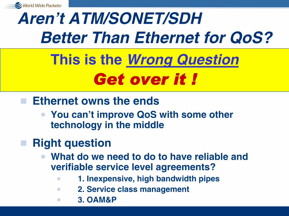
Aren’t ATM/SONET/SDH Better Than Ethernet for QoS?
g Ethernet owns the endsn You can’t improve QoS with some other
technology in the middle
g Right questionn What do we need to do to have reliable and
verifiable service level agreements?n 1. Inexpensive, high bandwidth pipesn 2. Service class managementn 3. OAM&P
This is the Wrong QuestionGet over it !Get over it !Get over it !Get over it !

Optical EthernetDeficiencies and Mitigation
g Fault Protection/Restoration Times
g Providing QoS
g Performance Monitoring and Fault Management
g Scalable OA&M Capabilities
These five slides derived from: Luke Maki, Boeing Corporation, 2002

Optical Ethernet Deficienciesg Fault Protection/Restoration Times
n > 1 second (industry likes 50 ms)n Contributors to restoration time:
n Original 802.1D Spanning Tree can take up to 50 seconds
n Aggregate link failover ‘one second or less’ per 802.3ad
g Mitigationn Spanning Tree improvements via 802.1s and
802.1w, bringing convergence to 1 secondn Actual aggregate link failover is being achieved
in 100 ms or less

Optical Ethernet Deficienciesg Providing QoS
n Over-provisioning bandwidth (higher network cost)
n CoS on aggregate traffic flows does not necessarily get applied where needed in the network
n Spanning Tree does not distribute traffic on available capacity
g Mitigationn Low cost of Ethernet allows for over-provisioningn 802.1s will enable better utilization of links
otherwise unused under 802.1D

Optical Ethernet Deficienciesg Performance Monitoring & Fault
Managementn Gigabit Ethernet (and less) provide NO
overhead for performance monitoring, alarms, etc.
n SNMP monitoring can be ‘after the fact’
g Mitigationn The 10GbE WAN interface provides a
limited set similar to SONETn The Ethernet First Mile Task Force is
working proposals to mitigate the issues

Optical Ethernet Deficienciesg Other OAM&P Capabilities
n Single-ended maintenancen Loopback testingn Flow-through provisioningn Integrated operations support systemsn Capacity planning and managementn Service level agreements
g Mitigationn EFM working on Layer 2 “OAM” featuresn Provisioning / OSS / BSS not Ethernetn Expect solutions from 802.1 and IETF

Ethernet QoS & OAM Summaryg Ethernet does not prohibit QoS
n Ethernet compliant equipment can (and does) support CoS, QoS, and provisioning
n QoS is solved above the Ethernet MACg Ethernet EFM project’s OAM resolves
issues with link diagnostics and management
n But, only on a single link basisn IETF solution required for end-to-end
diagnostics management (not 802.3’s job)

Trends and Influencesg Towards Simplificationg Towards Higher Speed; Lower Cost vs.
Moore’s Lawg Ethernet to the Rescue in the Access Spaceg QoS and OAM Can Be and Must Be Solvedg Economic Models Can Support “True
Broadband Services”g Distractions or Complementsg Federal Regulation and Policy Will Be the
Single Greatest Influence on Technology Development
g Investment as a Positive Feedback System

Household Budget
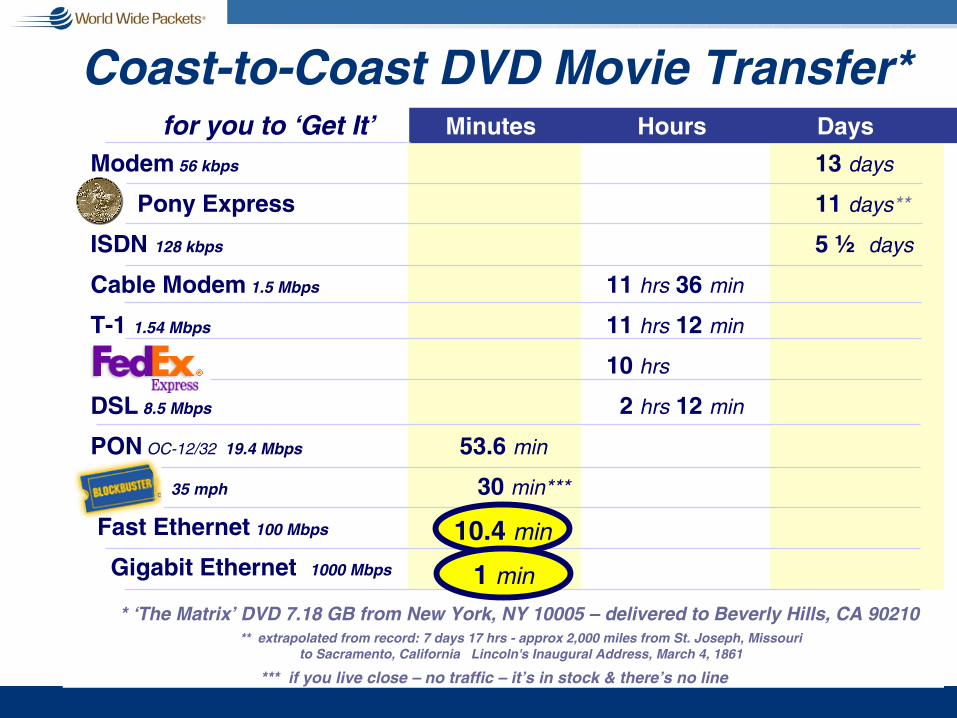
Coast-to-Coast DVD Movie Transfer*Minutes Hours Days
* ‘The Matrix’ DVD 7.18 GB from New York, NY 10005 – delivered to Beverly Hills, CA 90210
Modem 56 kbps 13 days
Pony Express 11 days**
ISDN 128 kbps 5 ½ days
Cable Modem 1.5 Mbps 11 hrs 36 min
T-1 1.54 Mbps 11 hrs 12 min
10 hrs
DSL 8.5 Mbps 2 hrs 12 min
PON OC-12/32 19.4 Mbps 53.6 min
35 mph 30 min***
Fast Ethernet 100 Mbps
Gigabit Ethernet 1000 Mbps
** extrapolated from record: 7 days 17 hrs - approx 2,000 miles from St. Joseph, Missouri to Sacramento, California Lincoln's Inaugural Address, March 4, 1861
*** if you live close – no traffic – it’s in stock & there’s no line
for you to ‘Get It’
10.4 min
1 min
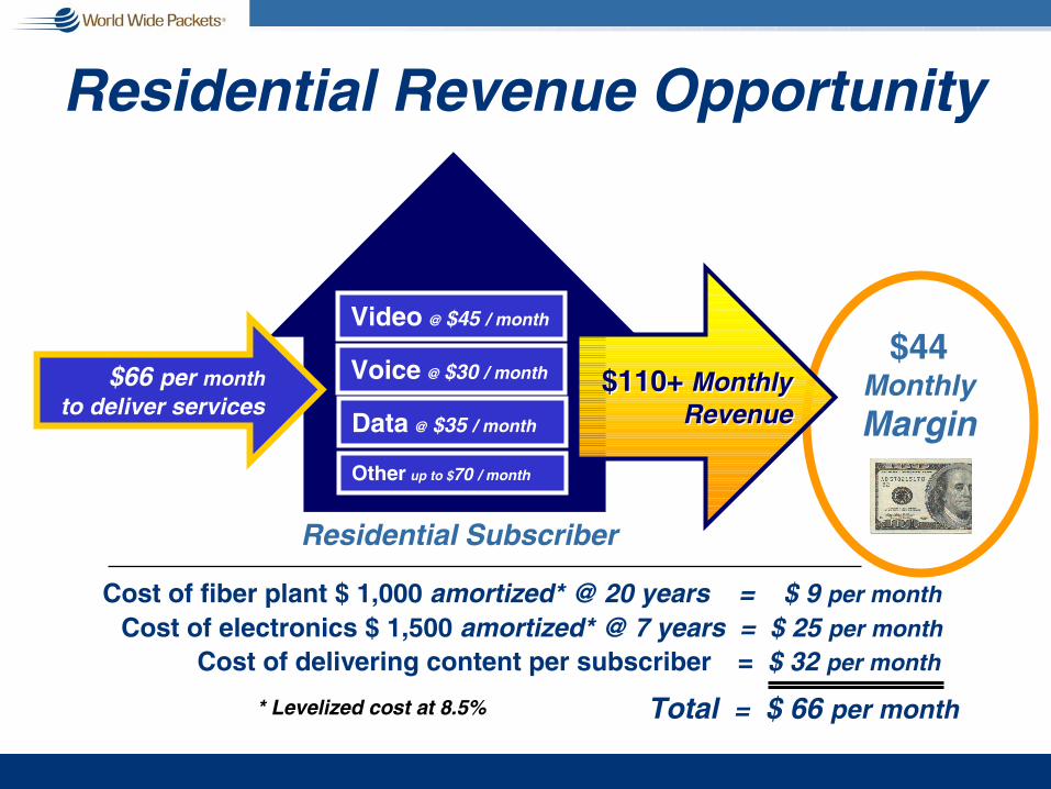
$44MonthlyMargin
Residential Revenue Opportunity
Voice @ $30 / month
Data @ $35 / month
Video @ $45 / month
Cost of electronics $ 1,500 amortized* @ 7 years = $ 25 per monthCost of fiber plant $ 1,000 amortized* @ 20 years = $ 9 per month
Cost of delivering content per subscriber = $ 32 per month
Total = $ 66 per month
$66 per monthto deliver services
Residential Subscriber
$110+ Monthly Revenue
$110+ Monthly Revenue
* Levelized cost at 8.5%
Other up to $70 / month

Payoff
Business Revenue Opportunity
Voice
Data
Cost of Lateral & Building Entrance – Fiber = $ 50,000
Total = $ xx,xxx
~1 year
$6,450Monthly Revenue
$6,450Monthly Revenue
75 Voice lines10,000 LD minutes
10 Mb Internet access10 Mb LAN interconnection
Capital Costs
Cost of Third-Party voice-switching equipment = $ 23,785Cost of Ethernet Access – 2 Gbps = $ x,xxx
Business VideoVideoconferencingTelemedicine
10 Office Multi-Tenant Business

6/18/02 WWP Community Networks 2002 2
Service Provider Summary
• 12 Internet Service Providers (ISPs)
• 2 Video Service Providers (VSPs)
• 1 Telephone Service Provider
• 1 Security Service Provider
June 7, 2002
Open Access Philosophy
Gig-E FTTH, business & farmLayer-2 transport

6/18/02 WWP Community Networks 2002 3
Construction Summary
• 7,110 Meters Passed (to-date)
• 6,436 Homes Passed
• 2,289 Customers Lit
• ~30-50 new customers per week
June 7, 2002
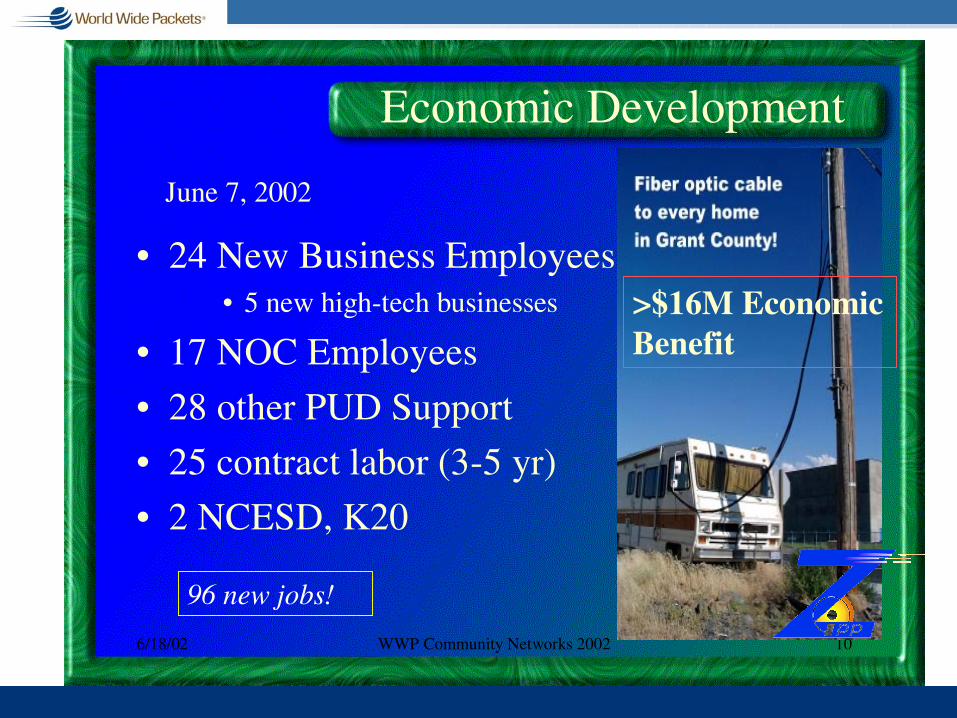
6/18/02 WWP Community Networks 2002 10
Economic Development
• 24 New Business Employees• 5 new high-tech businesses
• 17 NOC Employees
• 28 other PUD Support
• 25 contract labor (3-5 yr)
• 2 NCESD, K20
June 7, 2002
>$16M Economic Benefit
96 new jobs!

6/18/02 WWP Community Networks 2002 16
Lessons Learned
• Build it “once” to every home/business
• Supervision of contract labor• Multi-vendor interoperability
• Economic catalyst to avoid chicken & egg• Video IP Head-end, Telephone IP Gateway

6/18/02 WWP Community Networks 2002 17
Summary
• Grant County PUD FTTH Project– will influence community change by:
• Removing the access bottleneck
• Eliminating the impact of distance
• Removing the barrier to entry
• Open Access, non-discriminating pricing
• Digital imagination without limits

Trends and Influencesg Towards Simplificationg Towards Higher Speed; Lower Cost vs.
Moore’s Lawg Ethernet to the Rescue in the Access Spaceg QoS and OAM Can Be and Must Be Solvedg Economic Models Can Support “True
Broadband Services”g Distractions or Complementsg Federal Regulation and Policy Will Be the
Single Greatest Influence on Technology Development
g Investment as a Positive Feedback System

Distractions or Complements?EtherEveryThings
n Chip-to-Chip Communication?n 60-90 GHz Pt-to-Pt Radio?n Ethernet Disk Drives?n Subspace?
EtherKinn 802.11 -- “Wireless Ethernet?”n 802.17 – “Ethernet Loops” (RPR)
Othern Infiniband (NGIO -> Infiniband -> 3GIO -> ?)n Fibre Channel vs. iSCSIn Digital Wrappersn MPLS; VPLS;

Trends and Influencesg Towards Simplificationg Towards Higher Speed; Lower Cost vs.
Moore’s Lawg Ethernet to the Rescue in the Access Spaceg QoS and OAM Can Be and Must be Solvedg Economic Models Can Support “True
Broadband Services”g Distractions or Complementsg Federal Regulation and Policy Will Be the
Single Greatest Influence on Technology Development
g Investment as a Positive Feedback System
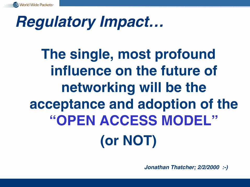
Regulatory Impact…
The single, most profound influence on the future of
networking will be the acceptance and adoption of the
“OPEN ACCESS MODEL”(or NOT)
Jonathan Thatcher; 2/2/2000 :-)

Reed E. Hundt 1
You Say You Want a Revolution (ISBN 0-300-08364-5)
g “Behind the existing rules, however, were two unwritten principles.
n First, by separating industries through regulation, government provided a balance of power in which each industry could be set against one another in order for elected figures to raise money from the different camps that sought advantageous regulation.
n Second, by protecting monopolies, the Commission could essentially guarantee that no communications businesses would fail. Repealing these implicit rules was a far less facile affair than promoting competition.”
11 Former Chairman of the FCC

Customer as Hostage
Wireless
Cable 1Cable 2
ISP
CLEC
ILEC
Satellite
Single Use Infrastructure

Who’sMonopolyIs It Anyway?
Community
TELCOsg Water
g Roadsg Sewers
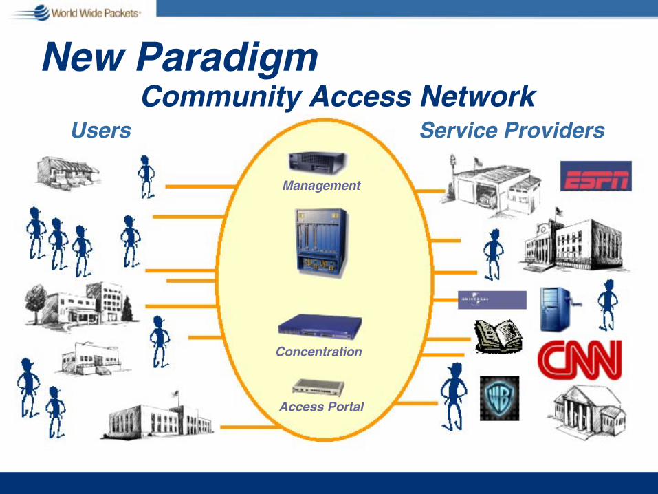
New Paradigm
Concentration
Access Portal
Community Access Network
Management
Users Service Providers

Customer Choice
Shared Infrastructure
Satellite 3Satellite 2
Satellite 1
Community Access Network
Operations Center
Wireless 2
Wireless 1
Cable 1Cable 2
Cable 3Cable 4
ISP 1ISP 2ISP 3ISP 4
CLEC 1CLEC 2CLEC 3CLEC 4
ILEC
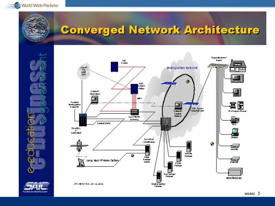

Clash of Paradigms
20th Century g Circuit switchedg Centralized g Voice driveng Value in metering
use g Deterministicg Monopoly
21st Century g Packet switchedg Decentralized g Data driven g Value apps and
servicesg Evolutionaryg Competitive
The Public Network at Bay
Source: Center for Internet Studies, 8/8/2002, Rex Hughes

Trends and Influencesg Towards Simplificationg Towards Higher Speed; Lower Cost vs.
Moore’s Lawg Ethernet to the Rescue in the Access Spaceg QoS and OAM Can Be and Must Be Solvedg Economic Models Can Support “True
Broadband Services”g Distractions or Complementsg Federal Regulation and Policy Will Be the
Single Greatest Influence on Technology Development
g Investment as a Positive Feedback System

Bandwidth Driving Revenue
Services Driving Bandwidth
Gigabit Ethernet1,000 Mbps
Dial-Up56 Kbps
ISDN128 Kbps
Cable Modem1.5 Mbps
ADSL8.5 Mbps
PON19.5 Mbps
Voice - 6.5 Kbps
Gaming
SDTV (1)
HDTV (1)
HDTV (2)
The Future ?
SDTV (2)
Web surfing
not drawn to scale …
20 Mbps
40 Mbps
10 Mbps
5 Mbps
2 Mbps
56 Kbps
~~
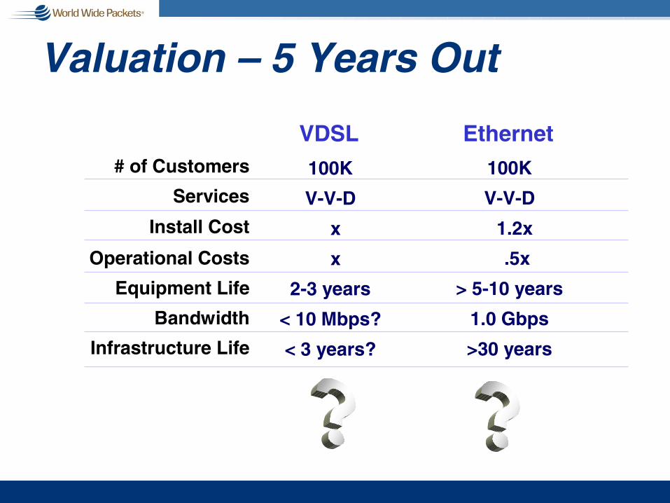
Valuation – 5 Years Out
100K
V-V-D
x
x
2-3 years
< 10 Mbps?
< 3 years?
VDSL Ethernet
Infrastructure Life
# of Customers
Services
Install Cost
Operational Costs
Equipment Life
Bandwidth
100K
V-V-D
1.2x
.5x
> 5-10 years
1.0 Gbps
>30 years
Company Value

10 Gigabit Ethernet Forecast
10 30
110
340
750
0
100
200
300
400
500
600
700
800
2002 2003 2004 2005 2006
Port Shipments (000s)
Source: Dell‘Oro Group (5/02) Worldwide Ethernet Switch Market

$0
$500
$1,000
$1,500
$2,000
$2,500
$3,000
$3,500
$4,000
2002 2003 2004 2005 2006
Manufacturer Revenue ($M)
Source: Dell‘Oro Group (5/02)Worldwide Ethernet Switch Market
10 Gigabit Ethernet Forecast

-
5,000
10,000
15,000
20,000
25,000
2002 2003 2004 2005 2006
M anufacturer ASP ($)
Source: Dell‘Oro Group (5/02)Worldwide Ethernet Switch Market
10 Gigabit Ethernet Forecast

10 Gigabit Ethernet Forecast
2002 2003 2004 2005 2006Manufacturer Revenue ($M) 250 525 1058.8 2290.8 3537.2
Port Shipments
(000s) 10 30 110 340 750Manufacturer
ASP ($) 25,000 17,500 9,625 6,738 4,716
Source: Dell‘Oro Group (5/02)Worldwide Ethernet Switch Market

10 Gig Ethernet Externalities“It’s the Economy Stupid”g Drivers
n Ethernet in the First Mile (2003-2004?)n Upgrades to Gigabit Enterprise Gear (?)n Ethernet over All Optical Networks (?)
g Volume / Price Tail Chasingg Mainstream Technologiesg Graphical & Video Applications
Related Organizations & Technologies

802.3ah & EFMA Roles
g An IEEE task forceg Create the EFM
standardg Address four areas
n OAMn Fiber Point-to-Pointn Fiber PONn Copper
g An industry allianceg Support the standards
process with resourcesg Market the technologyg Host interoperability
eventsg Proven concept
802.3ah EFMA

EFMA Goals
g Marketing Goalsn Create industry awareness, acceptance, and
advancement of the Ethernet in the First Mile standard and products
n Provide resources to establish and show multi-vendor interoperability through coordinated events
g Technical Goalsn Support the Ethernet in the First Mile standards effort
conducted in the IEEE 802.3ah Task Forcen Contribute technical resources to facilitate convergence
and consensus on technical specifications

Marketing & Technical
g Promotion Materialn First Whitepaper is out
g Speakers Bureaun Delivering the
message
g Participate in Eventsn Panels & info booths
g Technical Meetingsn First two conducted
g EFM Tutorialsn Broaden
understanding
g Inter-op Eventsn Prove products
interwork
Marketing Technical

10 GEA Missiong Promote industry awareness, acceptance,
and advancement of technology and products based on the emerging 10 Gigabit Ethernet standard
g Accelerate industry adoption by driving technical consensus and providing technical contributions to the IEEE 802.3ae Task Force
g Provide resources to establish and demonstrate multi-vendor interoperability of 10 Gigabit Ethernet products

What Is OIF?g Launched in April of 1998g Open forum: 320+ members including many
of the world’s leading carriers & vendorsg The only industry group bringing together
professionals from the packet & circuit worlds
g Mission: To foster the development and deployment of interoperable products and services for data switching and routing using optical networking technologies
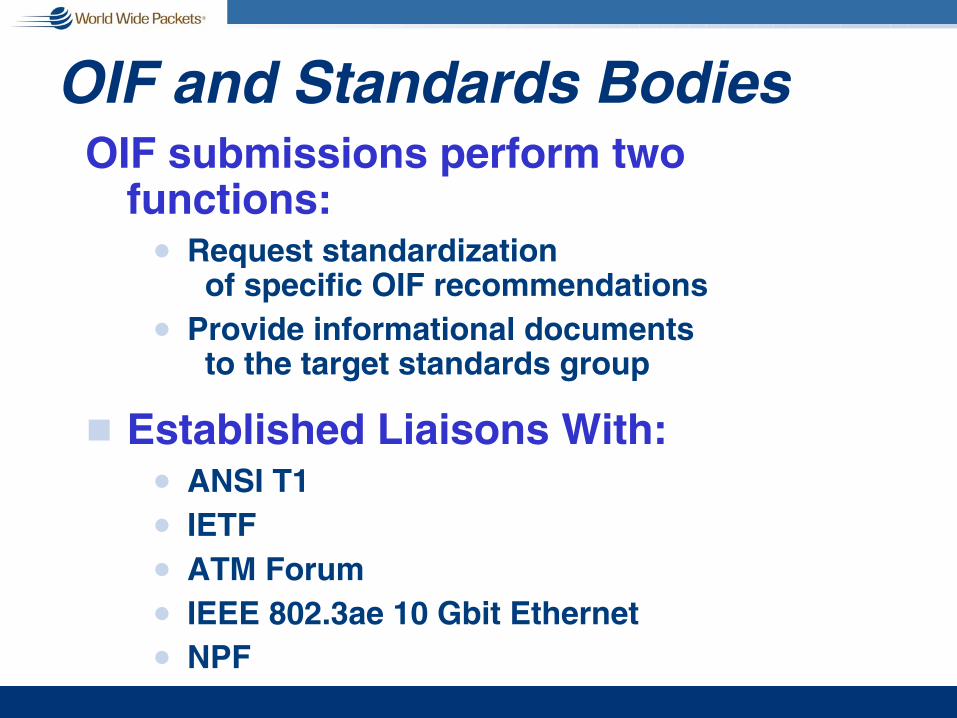
OIF and Standards BodiesOIF submissions perform two
functions:n Request standardization
of specific OIF recommendationsn Provide informational documents
to the target standards group
g Established Liaisons With:n ANSI T1n IETF n ATM Forumn IEEE 802.3ae 10 Gbit Ethernetn NPF

OIF Technical Committee g Architecture
n Services, network requirements, & architectures
g Carriern Requirements and applications
g Signalingn Protocols for automatic setup of lightpaths
g OAM&P - Operations, Administration, Maintenance & Provisioningn Network management
g Interoperabilityn Interoperability testing
g Physical & Link Layern Equipment & subsystem module interfaces
Six Working GroupsSix Working Groups

OIF Implementation Agreementsg SPI-3: System Packet Interface Level 3:g SPI-4 phase 1: System Physical Interface Level 4g SPI-4 phase 2: System Packet Interface Level 4g SFI-4: SERDES/Framer Electical Interface: Common
electrical interface between framers and serializer/deserializer parts for STS-192/STM-64 interfaces
g Very Short Reach (VSR) OC-192 Interface based on 12 fiber Parallel Optics
g Serial OC192 1310 nm Very Short Reach (VSR) Interfaces g Very Short Reach (VSR) OC-192 Interface
based on 4 fiber Parallel Optics g Serial OC192 850 nm Very Short Reach (VSR) Interfacesg Etc.

Parallel Optics-Based VSR Interface
1.24GbpsOptics
Pin-PD Array
1.24GbpsOptics
VCSEL Array
Parallel Ribbon Cable (<400m) 62.5um MM
VCSEL - Vertical Cavity Surface Emitting Laser (850nm wavelength)
10GFramer
10G10GFramerFramer
10G Optics10G 10G
OpticsOptics10G
Optics10G 10G
OpticsOptics10G
Framer10G10G
FramerFramer
10GFramer
10G10GFramerFramer
10GFramer
10G10GFramerFramer
16:12CONVERTER
16:1216:12CCOONNVVEERRTTEERR
16:12CONVERTER
16:1216:12CCOONNVVEERRTTEERR
Low speed parallel links
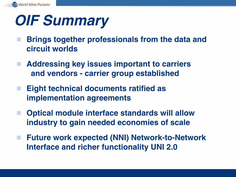
OIF Summaryg Brings together professionals from the data and
circuit worlds
g Addressing key issues important to carriers and vendors - carrier group established
g Eight technical documents ratified as implementation agreements
g Optical module interface standards will allow industry to gain needed economies of scale
g Future work expected (NNI) Network-to-Network Interface and richer functionality UNI 2.0

Fibre Channel and SAN 10GFC g ANSI T11 & IEEE continue to share
n Ethernet borrowed 1 Gb from FCn Fibre Channel 10G borrowed from Ethernet
g One common wire and XCVR technology to leverage economy of scale and one cable plant technology – user runs one type of cable for SAN & LAN
n Exception is that FC identifies a potentially more “Core SAN” cost effective option of 4-lane short wave optics (4 X 2.5) for 10G SAN solutions before 2004-7
n 850 nm version of the 10GBASE-LX4n Potential issue for iSCSI

Fibre Channel and SAN 10GFC g Key issue for 10G SAN - regardless of IO
technology - is timing of cost effective 10G Optical XCVRS
n Will 4-lane 10G optics be more cost effective than 1-lane 850nm 10G optics?
n SAN can not withstand expensive XVRS
n Meanwhile, 2G optics rule SAN while 4G copper enters in-box, loop application
g 4Gb FC is non-fabric, copper only, mostly CMOS, non-”SAN”, in-the-box disc storage “loop” migration and does not address same usage as 1, 2, & 10 Gb FC out-of-box SAN “fabric”
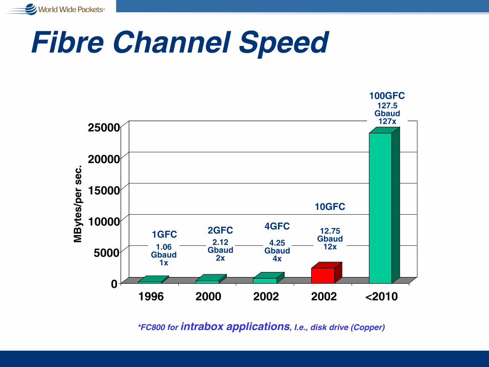
Fibre Channel Speed
0
5000
10000
15000
20000
25000
MB
ytes
/per
sec
.
1996 2000 2002 2002 <2010
1GFC1.06
Gbaud 1x
2GFC2.12
Gbaud 2x
4GFC
4.25 Gbaud
4x
10GFC
12.75 Gbaud
12x
100GFC127.5
Gbaud 127x
*FC800 for intrabox applications, I.e., disk drive (Copper)

Length
Ad
op
tio
nWill 10Gb Be “SANable”? When?
SAN Sweet Spotfor any IO Technology
n <300 meters mostly <100 meters
n <$500/GBIC (max!)mostly <$100 (10G will bear some premium, but not much)
n For 2004, translates to:4-lane optics (FC only) and/or850nm shortwave
Core SAN MarketCore SAN Market
SAN “Sweet Spot”

SAN Optical Transceiver Migration
0100200300400500600700800900
1000
2001 2002 2003 2004 2005
Per
Por
t C
ost
($)
2G OPTICAL serial (2G Cu Backend)
10G OPTICAL serial (XAUI Backend)
Integrated 4-lane CMOS 10G Copper (FC and IB Only), 2002 <$20/port4G FC Disks 1-lane CMOS Copper, 2003 <$10/port – No plans for 4G Optical xvr!
10G OPTICAL 4-lane (SX4; XAUI Backend)
?4G OPTICAL serial ?

Resistance Is Futile
No VoIP
10 Gigabit10 Gigabit10 GigabitEthernetEthernetEthernet
Ethernet
Limit Broadband
Shared Media
ADSL
Rules
Preserve our Copper Save
SONET/SDHModems
Forever


![07-ethernet.ppt - Carnegie Mellon School of Computer Sciencedga/15-441/S08/lectures/07-ethernet.pdf · Pkt t t t llid ith th kt t i [t 1t+1] 11 11 ... 21 21 collision? Ethernet Collision](https://static.documents.pub/doc/80x56/5c82fafb09d3f21e6b8d0757/07-carnegie-mellon-school-of-computer-science-dga15-441s08lectures07-ethernetpdf.jpg)


