65
No.EX##-OMN0003-A PRODUCT NAME EtherNet/IP TM Compatible Fieldbus System MODEL / Series / Product Number EX500-GEN1 etc.

No.EX##-OMN0003-A
PRODUCT NAME
EtherNet/IPTM Compatible Fieldbus System
MODEL / Series / Product Number
EX500-GEN1 etc.

-1-
No.EX##-OMN0003-A
Contents Safety Instructions 3 Product Summary 8 System configuration 8 EX500 GW unit Model indication and How to order 9 Summary of Product parts 9 Mounting and Installation 10 Installation 10 Wiring 10
Setting 18 EtherNet/IPTM CONFIGURATION WITH RSLogix5000TM 21 Specification 23 Specifications 23 Dimensions 25
SI unit Model indication and How to order 26 Summary of Product parts 27 Mounting and Installation 28 Installation 28
Setting 30 Specification 31 Specifications 31 Dimensions 33
Input Unit Manifold Model indication and How to order 34 Summary of Product parts 35 Mounting and Installation 36 Installation 36 Wiring 36
Setting 40 Specification 41 Specifications 41 Dimensions 42
EX9 series General Purpose Output Block Model indication and How to order 44 Summary of Product parts 45

-2-
No.EX##-OMN0003-A
Mounting and Installation 46 Installation 46 Wiring 47
Setting 49 Specification 50 Specifications 50 Dimensions 51
Troubleshooting 52 Option 62
-3-
No.EX##-OMN0003-A
Safety Instructions These safety instructions are intended to prevent hazardous situations and/or equipment damage. These instructions indicate the level of potential hazard with the labels of "Caution", "Warning" or "Danger". They are all important notes for safety and must be followed in addition to International standards (ISO/IEC) ∗1) and other safety regulations.
∗1) ISO 4414: Pneumatic fluid power -- General rules relating to systems ISO 4413: Hydraulic fluid power -- General rules relating to systems IEC 60204-1: Safety of machinery -- Electrical equipment of machines (Part 1: General requirements) ISO 10218-1992: Manipulating industrial robots -Safety. etc.
Caution : CAUTION indicates a hazard with a low level of risk which, if not avoided, could result in minor or moderate injury.
Warning : WARNING indicates a hazard with a medium level of risk which, if not avoided, could result in death or serious injury.
Danger : DANGER indicates a hazard with a high level of risk which, if not avoided, will result in death or serious injury.
Warning 1. The compatibility of the product is the responsibility of the person who designs the
equipment or decides its specifications. Since the product specified here is used under various operating conditions, its compatibility with specific equipment must be decided by the person who designs the equipment or decides its specifications based on necessary analysis and test results. The expected performance and safety assurance of the equipment will be the responsibility of the person who has determined its compatibility with the product. This person should also continuously review all specifications of the product referring to its latest catalog information, with a view to giving due consideration to any possibility of equipment failure when configuring the equipment.
2. Only personnel with appropriate training should operate machinery and equipment. The product specified here may become unsafe if handled incorrectly. The assembly, operation and maintenance of machines or equipment including our products must be performed by an operator who is appropriately trained and experienced.
3. Do not service or attempt to remove product and machinery/equipment until safety is confirmed. 1. The inspection and maintenance of machinery/equipment should only be performed after measures
to prevent falling or runaway of the driven objects have been confirmed. 2. When the product is to be removed, confirm that the safety measures as mentioned above are
implemented and the power from any appropriate source is cut, and read and understand the specific product precautions of all relevant products carefully.
3. Before machinery/equipment is restarted, take measures to prevent unexpected operation and malfunction.
4. Contact SMC beforehand and take special consideration of safety measures if the product is to be used in any of the following conditions.
1. Conditions and environments outside of the given specifications, or use outdoors or in a place exposed to direct sunlight.
2. Installation on equipment in conjunction with atomic energy, railways, air navigation, space, shipping, vehicles, military, medical treatment, combustion and recreation, or equipment in contact with food and beverages, emergency stop circuits, clutch and brake circuits in press applications, safety equipment or other applications unsuitable for the standard specifications described in the product catalog.
3. An application which could have negative effects on people, property, or animals requiring special safety analysis.
4. Use in an interlock circuit, which requires the provision of double interlock for possible failure by using a mechanical protective function, and periodical checks to confirm proper operation.
-4-
No.EX##-OMN0003-A
Caution The product is provided for use in manufacturing industries. The product herein described is basically provided for peaceful use in manufacturing industries. If considering using the product in other industries, consult SMC beforehand and exchange specifications or a contract if necessary. If anything is unclear, contact your nearest sales branch.
Limited warranty and Disclaimer/Compliance Requirements The product used is subject to the following "Limited warranty and Disclaimer" and "Compliance Requirements". Read and accept them before using the product.
Limited warranty and Disclaimer 1. The warranty period of the product is 1 year in service or 1.5 years after the product is delivered. ∗2)
Also, the product may have specified durability, running distance or replacement parts. Please consult your nearest sales branch.
2. For any failure or damage reported within the warranty period which is clearly our responsibility, a replacement product or necessary parts will be provided. This limited warranty applies only to our product independently, and not to any other damage incurred due to the failure of the product.
3. Prior to using SMC products, please read and understand the warranty terms and disclaimers noted in the specified catalog for the particular products.
∗2) Vacuum pads are excluded from this 1 year warranty. A vacuum pad is a consumable part, so it is warranted for a year after it is delivered. Also, even within the warranty period, the wear of a product due to the use of the vacuum pad or failure due to the deterioration of rubber material are not covered by the limited warranty.
Compliance Requirements 1. The use of SMC products with production equipment for the manufacture of weapons of mass
destruction (WMD) or any other weapon is strictly prohibited. 2. The exports of SMC products or technology from one country to another are governed by the
relevant security laws and regulation of the countries involved in the transaction. Prior to the shipment of a SMC product to another country, assure that all local rules governing that export are known and followed.

-5-
No.EX##-OMN0003-A
Operator
♦This operation manual is intended for those who have knowledge of machinery using pneumatic equipment, and have sufficient knowledge of assembly, operation and maintenance of such equipment. Only those persons are allowed to perform assembly, operation and maintenance.
♦Read and understand this operation manual carefully before assembling, operating or providing maintenance to the product.
Safety Instructions
Warning Do not disassemble, modify (including changing the printed circuit board) or repair. An injury or failure can result. Do not operate the product outside of the specifications. Do not use for flammable or harmful fluids. Fire, malfunction, or damage to the product can result. Verify the specifications before use. Do not operate in an atmosphere containing flammable or explosive gases. Fire or an explosion can result. This product is not designed to be explosion proof. If using the product in an interlocking circuit: •Provide a double interlocking system, for example a mechanical system. •Check the product regularly for proper operation. Otherwise malfunction can result, causing an accident. The following instructions must be followed during maintenance: •Turn off the power supply. •Stop the air supply, exhaust the residual pressure and verify that the air is released before performing maintenance.
Otherwise an injury can result.
Caution After maintenance is complete, perform appropriate functional inspections. Stop operation if the equipment does not function properly. Safety cannot be assured in the case of unexpected malfunction. Provide grounding to assure the safety and noise resistance of the Serial System. Individual grounding should be provided close to the product with a short cable.

-6-
No.EX##-OMN0003-A
NOTE Follow the instructions given below when designing, selecting and handling the product.
•The instructions on design and selection (installation, wiring, environment, adjustment, operation, maintenance, etc.) described below must also be followed. ∗Product specifications •The direct current power supply to combine should be UL1310 Class 2 power supply when conformity to UL is necessary.
•The product is a approved product only if they have a mark on the body. •Use the specified voltage.
Otherwise failure or malfunction can result. •Reserve a space for maintenance.
Allow sufficient space for maintenance when designing the system. •Do not remove any nameplates or labels.
This can lead to incorrect maintenance, or misreading of the operation manual, which could cause damage or malfunction to the product. It may also result in non-conformity to safety standards.
•Product handling ∗Installation •Do not drop, hit or apply excessive shock to the fieldbus system.
Otherwise damage to the product can result, causing malfunction. •Tighten to the specified tightening torque.
If the tightening torque is exceeded the mounting screws may be broken. IP65/67 protection cannot be guaranteed if the screws are not tightened to the specified torque.
•Never mount a product in a location that will be used as a foothold. The product may be damaged if excessive force is applied by stepping or climbing onto it.
∗Wiring •Avoid repeatedly bending or stretching the cables, or placing heavy load on them.
Repetitive bending stress or tensile stress can cause breakage of the cable. •Wire correctly.
Incorrect wiring can break the product. •Do not perform wiring while the power is on.
Otherwise damage to the fieldbus system and/or I/O device can result, causing malfunction. •Do not route wires and cables together with power or high voltage cables.
Otherwise the fieldbus system and/or I/O device can malfunction due to interference of noise and surge voltage from power and high voltage cables to the signal line. Route the wires (piping) of the fieldbus system and/or I/O device separately from power or high voltage cables.
•Confirm proper insulation of wiring. Poor insulation (interference from another circuit, poor insulation between terminals, etc.) can lead to excess voltage or current being applied to the product, causing damage.
•Take appropriate measures against noise, such as using a noise filter, when the fieldbus system is incorporated into equipment. Otherwise noise can cause malfunction.
•Separate the power line for output devices from the power line for control. Otherwise noise or induced surge voltage can cause malfunction.

-7-
No.EX##-OMN0003-A
∗Environment •Select the proper type of protection according to the environment of operation.
IP65/67 protection is achieved when the following conditions are met. (1) The units are connected properly with fieldbus cable with M12 connector and power cable with M12 (M8)
connector. (2) Suitable mounting of each unit and manifold valve. If using in an environment that is exposed to water splashes, please take measures such as using a cover. If the product is to be used in an environment containing oils or chemicals such as coolant or cleaning solvent, even for a short time, it may be adversely affected (damage, malfunction etc.).
•Do not use the product in an environment where corrosive gases or fluids could be splashed. Otherwise damage to the product and malfunction can result.
•Do not use in an area where surges are generated. If there is equipment which generates a large amount of surge (solenoid type lifter, high frequency induction furnace, motor, etc.) close to the fieldbus system, this may cause deterioration or breakage of the internal circuit of the fieldbus system. Avoid sources of surge generation and crossed lines.
•When a surge-generating load such as a relay or solenoid is driven directly, use an fieldbus system with a built-in surge absorbing element. Direct drive of a load generating surge voltage can damage the fieldbus system.
•The product is CE marked, but not immune to lightning strikes. Take measures against lightning strikes in the system.
•Prevent foreign matter such as remnant of wires from entering the fieldbus system to avoid failure and malfunction.
•Mount the product in a place that is not exposed to vibration or impact. Otherwise failure or malfunction can result.
•Do not use the product in an environment that is exposed to temperature cycle. Heat cycles other than ordinary changes in temperature can adversely affect the inside of the product.
•Do not expose the product to direct sunlight. If using in a location directly exposed to sunlight, shade the product from the sunlight. Otherwise failure or malfunction can result.
•Keep within the specified ambient temperature range. Otherwise malfunction can result.
•Do not operate close to a heat source, or in a location exposed to radiant heat. Otherwise malfunction can result.
∗Adjustment and Operation •Perform settings suitable for the operating conditions.
Incorrect setting can cause operation failure. •Please refer to the PLC manufacturer's manual etc. for details of programming and addresses.
For the PLC protocol and programming refer to the relevant manufacturer's documentation.
∗Maintenance •Turn off the power supply, stop the supplied air, exhaust the residual pressure and verify the release of air before performing maintenance. There is a risk of unexpected malfunction.
•Perform regular maintenance and inspections. There is a risk of unexpected malfunction.
•After maintenance is complete, perform appropriate functional inspections. Stop operation if the equipment does not function properly. Otherwise safety is not assured due to an unexpected malfunction or incorrect operation.
•Do not use solvents such as benzene, thinner etc. to clean the each unit. They could damage the surface of the body and erase the markings on the body. Use a soft cloth to remove stains. For heavy stains, use a cloth soaked with diluted neutral detergent and fully squeezed, then wipe up the stains again with a dry cloth.

-8-
No.EX##-OMN0003-A
Product Summary System configuration
The Fieldbus system is connected to open fieldbus (EtherNet/IPTM) realizes the reduced wiring and decentralized installation of I/O devices. The signals to/from fieldbus are exchanged by GW unit, and the signals to/from decentralized I/O devices are collected and delivered by GW unit. The maximum number of connections of manifold valve/Input unit manifold is 16/branch x 4 branches = 64 points each for output and input. As the cables with M12 connectors are used for all wirings among devices, the system complies with the IP65 environment.

-9-
No.EX##-OMN0003-A
EX500 GW unit
Model indication and How to order
Summary of Product parts
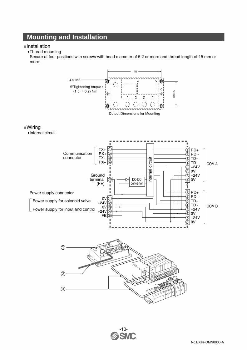
No. Description Function 1 Communication connector Connect with EtherNet/IPTM line. ∗1
2 Power supply connector Supply power for output devices such as solenoid valve, for input devices such as sensor, and for controlling GW/SI by using power supply connector cable. ∗1
3 Communication port A (COM A) 4 Communication port B (COM B) 5 Communication port C (COM C) 6 Communication port D (COM D)
Connect SI unit (manifold valve) or Input unit by using branch cable with M12 connectors. ∗1
7 Display Display the power supply status and communication status with PLC. ∗2
8 Station number switch protective cover Set IP address and communication method by using the switches under this cover. ∗2
9 Ground terminal Functional earth (FE). ∗1: For wiring method, refer to subsection "Wiring" (page 10) of section "EX500 GW unit" in this manual. ∗2: For display and setting method, refer to subsection "Setting" (page 18) of section "GW unit" in this manual.
-10-
No.EX##-OMN0003-A
Mounting and Installation Installation
•Thread mounting Secure at four positions with screws with head diameter of 5.2 or more and thread length of 15 mm or more.
Wiring •Internal circuit
-11-
No.EX##-OMN0003-A
The wirings are described in the following order.
↓
↓
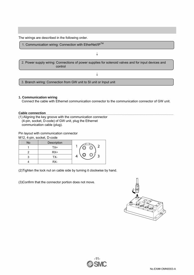
1. Communication wiring Connect the cable with Ethernet communication connector to the communication connector of GW unit.
Cable connection (1) Aligning the key groove with the communication connector
(4-pin, socket, D-code) of GW unit, plug the Ethernet communication cable (plug).
Pin layout with communication connector M12, 4-pin, socket, D-code
No Description 1 TX+ 2 RX+ 3 TX- 4 RX-
(2)Tighten the lock nut on cable side by turning it clockwise by hand. (3)Confirm that the connector portion does not move.
1. Communication wiring: Connection with EtherNet/IPTM
2. Power supply wiring: Connections of power supplies for solenoid valves and for input devices and control
3. Branch wiring: Connection from GW unit to SI unit or Input unit

-12-
No.EX##-OMN0003-A
Pin layout and connection diagram of cable with Ethernet communication connectors Connect the communication cable with plug-type M12 connector to the communication connector of GW unit.
Cable specifications Core wire colour AWG 26
Sheath color Blue green
Pin No. Cable color:Signal name
1 Yellow or White/Orange: TX+ 2 White or White/Green : RX+ 3 Orange : TX- 4 Blue or Green : RX-

-13-
No.EX##-OMN0003-A
2. Power supply wiring Connect the power supply connector cable which connector type have straight and angle to the power supply connector of GW unit. With this cable, the power is supplied to the output devices such as solenoid valve, and the input devices such as sensor, and for control. Therefore, there is no need to supply the power to other units individually. When selecting the power supply, refer to "Safety Instructions" (page 3) in this manual.
Cable connection (1) Aligning the key groove with the power supply connector
(plug) of GW unit, plug the power supply cable (socket) (2)Tighten the lock nut on cable side by turning it
clockwise by hand. (3)Confirm that the connector portion does not move.
Pin layout and connection diagram of power supply connector cable for (unit: mm) (Pin layout and connection diagram are common to all cables.)
Pin No. Cable color: Signal name
1 Brown: 0 V (for solenoid valves) 2 White: 24 VDC+10%/-5% (for solenoid valves) 3 Blue: 0 V (for input and control) 4 Black: 24 VDC ±10% ( for input and control) 5 Gray: Ground (FE)

-14-
No.EX##-OMN0003-A
FE connection
Separate wiring for power supply for solenoid valves/output and for input and control of GW/SI Both single power supply and two power supply systems can be adopted, however, the wiring shall be made separately (for solenoid valves and for input and control) for either system.
A. Dual power supply system
B. Single power supply system
NOTE Connect the ground terminal to the ground. Resistance to the ground should be 100 ohms or less.
-15-
No.EX##-OMN0003-A
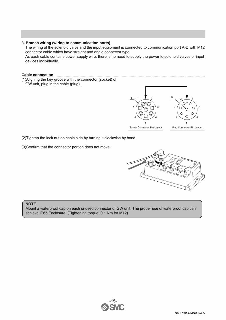
3. Branch wiring (wiring to communication ports) The wiring of the solenoid valve and the input equipment is connected to communication port A-D with M12 connector cable which have straight and angle connector type. As each cable contains power supply wire, there is no need to supply the power to solenoid valves or input devices individually.
Cable connection (1)Aligning the key groove with the connector (socket) of
GW unit, plug in the cable (plug).
(2)Tighten the lock nut on cable side by turning it clockwise by hand. (3)Confirm that the connector portion does not move.
NOTE Mount a waterproof cap on each unused connector of GW unit. The proper use of waterproof cap can achieve IP65 Enclosure. (Tightening torque: 0.1 Nm for M12)

-16-
No.EX##-OMN0003-A
For GW unit – Manifold valve – Input unit manifold configuration Two communication connectors in SI unit and one communication connector in Input unit are installed respectively. To the communication connector (C2) or (1) of SI unit, connect the branch cable with M12 connector from GW. To the communication connector (C1) or (0), connect the branch cable with M12 connector from Input unit. To the communication connector of Input unit, connect the branch cable with M12 connector from SI unit.
NOTE When no Input unit is connected to the connector (C1) or (0) of SI unit, mount a terminal plug on the connector.

-17-
No.EX##-OMN0003-A
For GW unit – Input unit manifold configuration To the communication connector of Input unit, connect the branch cable with M12 connector from GW unit.
Branch cable with M12 connector (EX500-AC-SP)
-18-
No.EX##-OMN0003-A
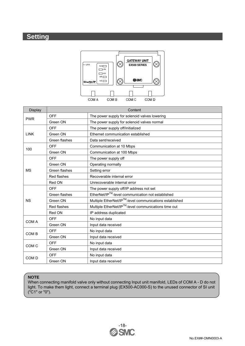
Setting
Display Content OFF The power supply for solenoid valves lowering
PWR Green ON The power supply for solenoid valves normal OFF The power supply off/initialized Green ON Ethernet communication established LINK Green flashes Data sent/received OFF Communication at 10 Mbps
100 Green ON Communication at 100 Mbps OFF The power supply off Green ON Operating normally Green flashes Setting error Red flashes Recoverable internal error
MS
Red ON Unrecoverable internal error OFF The power supply off/IP address not set Green flashes EtherNet/IPTM-level communication not established Green ON Multiple EtherNet/IPTM-level communications established Red flashes Multiple EtherNet/IPTM-level communications time out
NS
Red ON IP address duplicated OFF No input data
COM A Green ON Input data received OFF No input data
COM B Green ON Input data received OFF No input data
COM C Green ON Input data received OFF No input data
COM D Green ON Input data received
NOTE When connecting manifold valve only without connecting Input unit manifold, LEDs of COM A - D do not light. To make them light, connect a terminal plug (EX500-AC000-S) to the unused connector of SI unit ("C1" or "0").
-19-
No.EX##-OMN0003-A
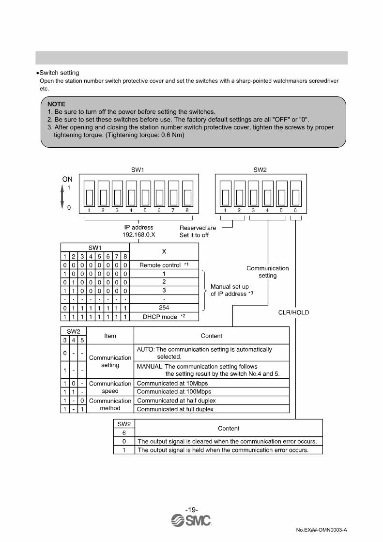
•Switch setting Open the station number switch protective cover and set the switches with a sharp-pointed watchmakers screwdriver etc.
NOTE 1. Be sure to turn off the power before setting the switches. 2. Be sure to set these switches before use. The factory default settings are all "OFF" or "0". 3. After opening and closing the station number switch protective cover, tighten the screws by proper
tightening torque. (Tightening torque: 0.6 Nm)
-20-
No.EX##-OMN0003-A
∗1: Remote control (SW1 all dip-switches off) SMC's EX500 GW Unit will respond to the following Rockwell Automation BOOTP/DHCP Server commands.
Enable DHCP Selecting this function will enable the EX500 GW Unit to retrieve its boot information from the BOOTP/DHCP Server. If DHCP is enabled the EX500 GW Unit will retrieve its boot information during the next power up.
Disable BOOTP/DHCP Selecting this function will disable the EX500 to retrieve its boot information from the BOOTP/DHCP Server, and causes the EX500 to retain its current configuration during the next power up.
∗2: DHCP Mode (SW1 all dip-switches on) The IP address is acquired via DHCP Server. The IP address is not saved and lost if the power to the EX500 unit is cycled.
∗3: Hardware Addressing The IP address range is 192.168.0.1 to 192.168.0.254.
Default settings At the time of factory shipment, the product is in "Remote Control Mode" and set to "Enable DHCP".
NOTE Remote Control mode If the EX500 IP address is unknown, change to DHCP mode and re-assign the correct IP address. When the DHCP server has assigned the correct address, turn off the power supply and return the unit to Remote control mode. Upon power-up, the EX500 will now be available using the address that was set whilst in DHCP mode. <Caution> If an IP address is set manually using the DIP-switches the EX500 will disable BOOTP/DHCP mode. If the unit is changed from a manual IP address setting to Remote control mode, the manually set IP address will be stored.

-21-
No.EX##-OMN0003-A
EtherNet/IPTM CONFIGURATION WITH RSLogix5000TM When setting up the node with RSLogix5000TM, specific values must be entered for the assembly instance with regards to Input, Output and Configuration. Please see the diagram below for a Rockwell Automation’s RSLogix5000TM programming software example.
∗: PLC software RSLogix5000TM manufactured by Rockwell Automation is shown above. RSLogix5000TM is a registered trademark of
Rockwell Automation. Connection Parameter
Assembly Instance values: Description Decimal
Comm Format "Data-INT" "Data-SINT" Input 100 100 Output 150 150 Configuration 1 1
Size: Description Size
Comm Format "Data-INT" "Data-SINT" Input 8words 16bytes Output 8words 16bytes Configuration 0word 0byte
EX500_GEN1_1
16
16
ETHERNET-MODULE EX500-GEN1_1
ETHERNET-MODULE EX500-GEN1_2
ETHERNET-MODULE EX500-GEN1_3

-22-
No.EX##-OMN0003-A
•I/O mapping The GW unit can control 128 input/output points in total. Regardless of I/O points of the equipment, it always occupies each data memory area for 64 inputs and 64 outputs.
Input area mapping
Input data MSB LSB MSB LSB Offset
(word) 15 8 7 0
0 IN15 ~ COM-A ~ IN0 1 IN15 ~ COM-B ~ IN0 2 IN15 ~ COM-C ~ IN0 3 IN15 ~ COM-D ~ IN0
Sensor input area
4 L L L L L L L L L L L L L L L L 5 L L L L L L L L L L L L L L L L 6 L L L L L L L L L L L L L L L L 7 L L L L L L L L L L L SOLV IN-A IN-B IN-C IN-D
L: Fixed to Low (reserved area)
Status input area
Status input area specifications Item Status Condition
1) The input unit detected 0
2) The SI unit with terminal plug detected IN-∗ The connection of branched bus1 Wire open detected 0 Supply voltage OK
SOLV The power supply for solenoid
valves 1 Supply voltage below lower limit
Output area mapping Output data
MSB LSB MSB LSB Offset (word)
15 8 7 0
0 OUT15 ~ COM-A ~ OUT0 1 OUT15 ~ COM-B ~ OUT0 2 OUT15 ~ COM-C ~ OUT0 3 OUT15 ~ COM-D ~ OUT0
Output area
4 L L L L L L L L L L L L L L L L 5 L L L L L L L L L L L L L L L L 6 L L L L L L L L L L L L L L L L 7 L L L L L L L L L L L L L L L L
L: Fixed to Low (reserved area)

-23-
No.EX##-OMN0003-A
Specification Specifications Basic specifications
Item Specification Rated voltage 24 VDC
Power supply voltage range Power supply for input and controlling: 24 VDC±10% Power supply for solenoid valves: 24 VDC+10%/-5% (Voltage drop warning at around 20 V)
Rated current
Power supply for input and control : 3 A Inside GW unit : 0.2 A Input device and SI control section : 2.8 A Power supply for solenoid valve : 3 A
Number of input/output points Input point: Max. 64/Output point: Max. 64 Standards CE marking. UL (CSA) Weight 470 g
Accessory: waterproof cap (for M12 connector socket) EX9-AWTS (5 pcs.)
Environment specifications
Item Specification Enclosure IP65 Operating temperature range Operating: 5 to 45 oC Stored: –25 to 70 oC (with no freezing and condensation) Operating humidity range Operating, Stored: 35 to 85%RH (with no condensation)
Withstand voltage 1000 VAC applied 1 minute Insulation resistance 2 MΩ or more (500 VDC Mega) between whole charging part and case
Operating atmosphere No corrosive gas Pollution degree For use in Pollution degree 3 Environment
Higher-level bus
Item Specification Protocol Ethernet (IEEE802.3)
Media 100BASE-TX Communication speed 10M/100Mbps (Automatic selection or manual setting) Max. segment length 100m (328ft) Max. transceiver number 2 (per segment)
Communication method Full duplex/Half duplex (automatic selection or manual setting) Fieldbus protocol EtherNet/IP™ Release1.0
I/O message Input : 16 byte (assembly instance: 100) Output : 16 byte (assembly instance: 150)
Port No. 44818 (0xAF12)
IP address setting range 192.168.0.1 to 192.168.0.254 (Setting by an internal switch) Or optional setting by the DHCP server
Subnet mask 255. 255. 255. 0 fixed
Device information Vendor ID : 7 (SMC Corp.) Product type : 12 (communication adapter) Product code : 104

-24-
No.EX##-OMN0003-A
Lower-level bus Item Specification
Number of branches for input/output
4 branches (16 points/branch) for input 4 branches (16 points/branch) for output
Communication method Protocol : Dedicated for SMC Speed : 750kbps
Branch current for input (Note) Max. 0.7 [A] per branch
Branch current for output Max. 0.65 [A] per branch (when SI unit EX500-S001 is connected) Max. 0.75 [A] per branch (when SI unit EX500-Q 0 is connected)
Branch cable length 5m or less between devices (total extended length: 10m or less)
-25-
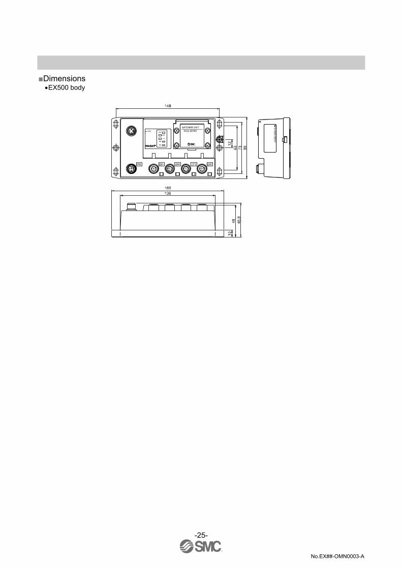
No.EX##-OMN0003-A
Dimensions •EX500 body
-26-
No.EX##-OMN0003-A
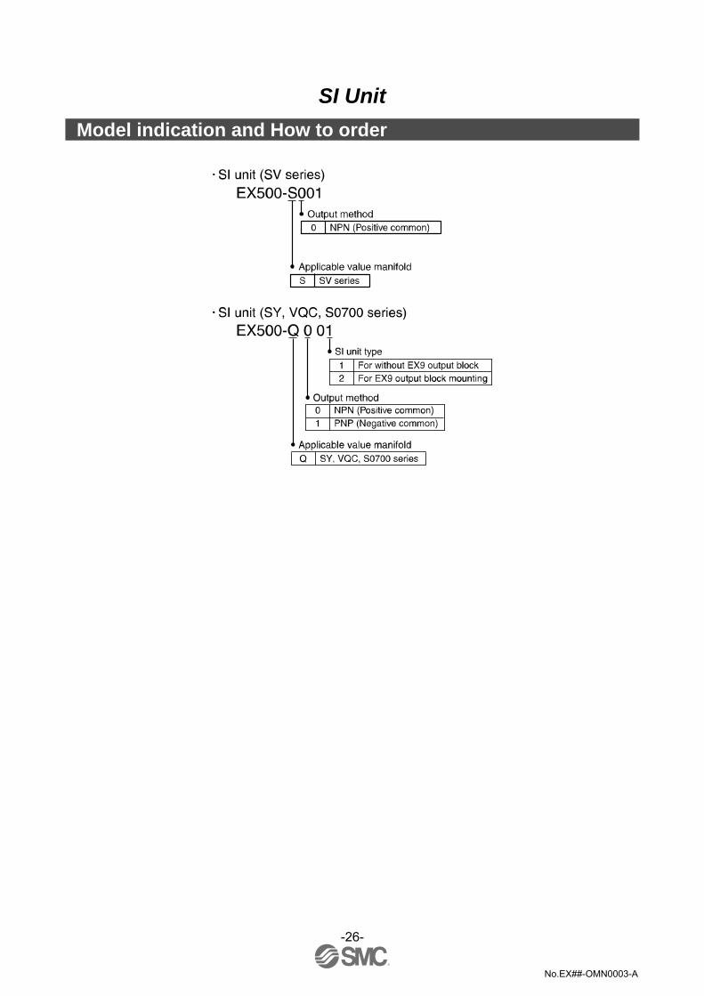
SI Unit
Model indication and How to order

-27-
No.EX##-OMN0003-A
Summary of Product parts The SI unit is the unit to communicate with GW unit in combination with manifold valve. It can be used with SV series valves, SY series valves, VQC series valves and S0700 series valves. In addition, this unit is able to operate solenoid valves, relays. etc. in combination with EX9 series general purpose output block. For how to use it, refer to section "EX9 Series General Purpose Output Block" (page 44) in this manual. 1. SI unit for SV series valves (EX500-S001)
2. SI unit for SY/VQC/S0700 series valves (EX500-Q 0 )
Common to EX500-S001/EX500-Q 0
No. Description Function
1 Communication connector "C1" or "0"
Connects the branch cable to Input unit (branch cable with M12 connector) ∗1
2 Communication connector "C2" or "1"
Connects the branch cable from GW unit (branch cable with M12 connector) ∗2
3 Power LED Indicates the power supply status. ∗2 4 Communication LED Indicates the communication status with GW unit. ∗2
∗1: For wiring method, refer to subsection "Wiring" (page 10) of section "EX500 GW unit" in this manual. ∗2: For display, refer to "Setting" (page 30) in section "SI Unit" in this manual.
12
12

-28-
No.EX##-OMN0003-A
Mounting and Installation Installation
The mounting and removing methods of SI unit are as shown below.
∗1: For branch wiring method, refer to subsection "Wiring" (page 10) of section "EX500 GW unit" in this manual. As the power to output
devices such as solenoid valve is supplied by branch wiring (branch cable with M12 connector), there is no need to supply power individually.
∗2: For mounting/installation methods of solenoid valve, manifold, etc., refer to the catalogs, instruction manuals, technical data, etc. of each valve series. When connecting general purpose output block only, refer to subsection "Mounting and installation" (page 46) of section "EX9 Series General Purpose Output Block" in this manual.
NOTE Holding with hand so that there will be no gap between SI unit and Air supply/exhaust block assembly, tighten the bolts. Be sure to tighten each bolt by specified tightening torque. (Tightening torque: 0.6 Nm)

-29-
No.EX##-OMN0003-A
Output number assignment
∗: The output number refers to the D side solenoid position on the manifold and starts at zero. ∗: Standard wiring on the manifold is for double-solenoid valves and output number starts A side and B side in that order as shown in
the figure a. If you mount a single-solenoid valve on the standard wiring manifold, output number for B side valve is skipped.
∗: Custom wiring for mixed mounting single-solenoid valves and double-solenoid-valves can be specified with a Wiring Specification Sheet. Example wiring is shown in the figure b.
-30-
No.EX##-OMN0003-A
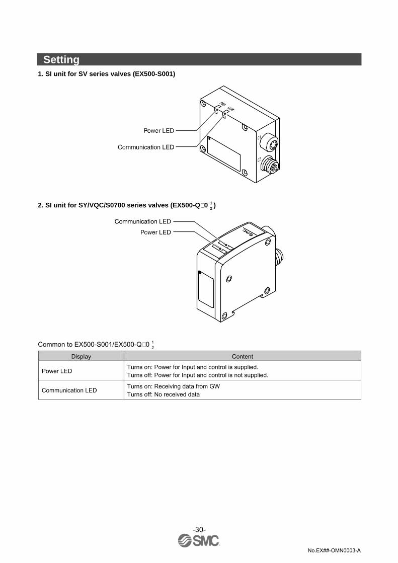
Setting 1. SI unit for SV series valves (EX500-S001)
2. SI unit for SY/VQC/S0700 series valves (EX500-Q 0 )
Common to EX500-S001/EX500-Q 0
Display Content
Power LED Turns on: Power for Input and control is supplied. Turns off: Power for Input and control is not supplied.
Communication LED Turns on: Receiving data from GW Turns off: No received data
12
12

-31-
No.EX##-OMN0003-A
Specification Specifications 1. SI unit for SV series valve (EX500-S001)
Item Specification
Connected block Solenoid valve (single, double) Relay output module (1-point output, 2- point output)
Double solenoid valve Relay output module (2-point output)
Max. 8 stations Connected block station
Single solenoid valve Relay output module (1-point output)
Max. 16 stations
Output type NPN (Positive common) Supply voltage for block 24 VDC Supply current for block 0.65 A Max. Current consumption 100 mA or less (at rated voltage) Enclosure IP65
Operating temperature range Operating: 5 to 45 oC Stored: –25 to 70 oC (with no freezing and condensation)
Operating humidity range Operating, Stored: 35 to 85%RH (with no condensation)
Withstand voltage 1000 VAC applied 1 minute Insulation resistance 2 MΩ or more (500 VDC Mega) between whole charging part and case
Operating atmosphere No corrosive gas Pollution degree For use in Pollution Degree 3 Environment Standards CE marking. UL (CSA) Weight 115 g
Accessory: waterproof cap (for M8 connector socket)
EX9-AWTS (1 pc.)

-32-
No.EX##-OMN0003-A
2. SI unit for VQC/S0700 series valve (EX500-Q 0 )
Item Specification
Connected block Solenoid valve (single, double) General purpose output block (EX500-Q 02 only)
Double solenoid valve Max. 8 stations Single solenoid valve Max. 16 stations
Connected block station General purpose output block (EX500-Q 02 only)
Max. 8 stations
Q00 NPN (Positive common) Output type
Q10 PNP (Negative common) Supply voltage for block 24 VDC Supply current for block 0.75 A max. Current consumption 100 mA or less (at rated voltage) Enclosure IP65
Operating temperature range Operating: 5 to 45 oC Stored: –25 to 70 oC (with no freezing and condensation)
Operating humidity range Operating, Stored: 35 to 85%RH (with no condensation)
Withstand voltage 1000 VAC applied 1 minute Insulation resistance 2 MΩ or more (500 VDC Mega) between whole charging part and case
Operating atmosphere No corrosive gas Pollution degree For use in Pollution Degree 3 Environment Standards CE marking. UL (CSA) Weight 105 g
Accessory: waterproof cap (for M8 connector socket) EX9-AWTS (1 pc.)
3. Applicable valve series
For detailed specifications of solenoid valve and manifold, refer to the catalogs, operation manuals, technical data, etc. of each valve series.
SV1000/2000/3000/4000 SY3000/5000 VQC1000/2000/4000 S0700
12
-33-
No.EX##-OMN0003-A
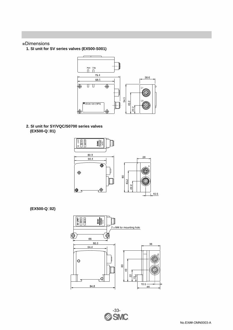
Dimensions
1. SI unit for SV series valves (EX500-S001)
2. SI unit for SY/VQC/S0700 series valves (EX500-Q 01)
(EX500-Q 02)
-34-
No.EX##-OMN0003-A
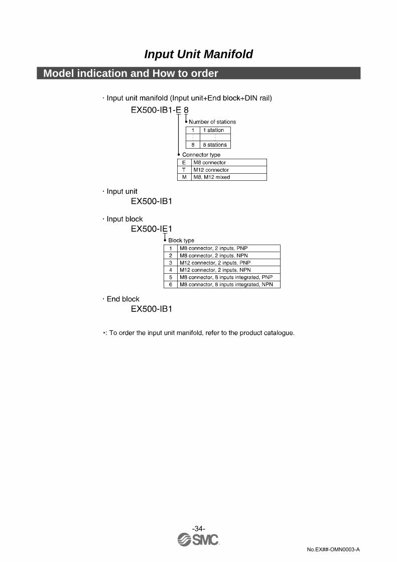
Input Unit Manifold
Model indication and How to order

-35-
No.EX##-OMN0003-A
Summary of Product parts The Input unit manifold consists of Input unit, input block (s), end block and DIN rail. The input block up to 8 can be connected (16 points). Any combination of input blocks (for M8 connector, M12 connector and 8-point integrated type, NPN and PNP) is acceptable.
Figure shows the configuration when only input blocks for M8 connector are connected.
No. Description Function 1 Input unit Unit to communicate with GW unit.
2 Communication connector To be connected with branch cables from GW unit or SI unit (branch cable with M12 connector) ∗1
3 Power LED Indicates the power supply status. ∗2 4 Input block Unit for sensor signal input. 5 Sensor connector Connects with sensor. ∗1 6 Indicator LED Indicates sensor signal status. ∗2 7 Marker (attached) To be used for writing input No. etc. 8 End block Composes the end of Input unit manifold. 9 DIN rail To be mounted with Input unit manifold.
∗1: For wiring method, refer to subsection "Wiring" (page 10) of section "EX500 GW unit" in this manual. ∗2: For display, refer to "Setting" (page 40) in section "Input Unit Manifold" in this manual.

-36-
No.EX##-OMN0003-A
Mounting and Installation Installation
1. Connect each connector of Input unit, input blocks, and end block (portion indicated by arrow in the figure to the bellow).
2. Holding with hands so that there will be no gap between blocks, place the jointed unit and blocks on DIN rail.
3. Tighten the bolts of Input unit and end block to secure the jointed unit and blocks to DIN rail. Be sure to tighten the bolts by proper tightening torque. (Tightening torque: 0.6 Nm)
Wiring
•Branch wiring For wiring method, refer to subsection "Wiring" (page 10) of section "EX500 GW unit" in this manual. To input devices such as sensor, the power is supplied through the branch wiring (branch cable with M12 connector). Therefore, there is no need to supply the power to them individually.
•Sensor wiring Connect sensors to the sensor connectors of input block.

-37-
No.EX##-OMN0003-A
Pin layout of sensor connector
M8 connector (3-pin socket) M12 connector (4-pin socket) No. Description No. Description 1 Power supply (24 VDC) 1 Power supply (24 VDC)3 Power supply (0 V) 2 (Input) ∗
3 Power supply (0 V) 4 Input
4 Input
∗: Internal wiring of M12 input block and key position for mounting sensor connector
•No. 2 pins of M12 input block connectors are wired to each other’s sensor signal input pins (No. 4 pins) internally.
•This wiring enables direct input of signals from two points combined into one cable through concentric connector etc.
•When connecting sensors, confirm the specification of output signal carefully. Otherwise malfunction can result.
•The key position for mounting sensor connector is as shown to the right. Consider this key position when selecting sensor.
NOTE Mount a waterproof cap on each unused connector of Input unit. The proper use of waterproof cap can achieve IP65 Enclosure. (Tightening torque: 0.05 Nm for M8 and 0.1 Nm for M12)

-38-
No.EX##-OMN0003-A
Sensor wiring example EX500-IE1/-IE5: M8, 3 pin PNP input block
EX500-IE2/-IE6: M8, 3 pin NPN input block

-39-
No.EX##-OMN0003-A
EX500-IE3: M12, 4 pin PNP input block
EX500-IE4: M12, 4 pin NPN input block
-40-
No.EX##-OMN0003-A
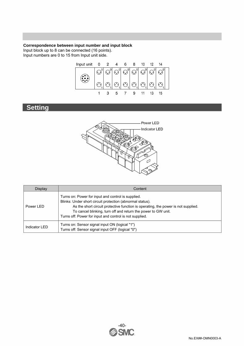
Correspondence between input number and input block Input block up to 8 can be connected (16 points). Input numbers are 0 to 15 from Input unit side.
Setting
Display Content
Power LED
Turns on: Power for input and control is supplied. Blinks: Under short circuit protection (abnormal status).
As the short circuit protective function is operating, the power is not supplied. To cancel blinking, turn off and return the power to GW unit.
Turns off: Power for input and control is not supplied.
Indicator LED Turns on: Sensor signal input ON (logical "1") Turns off: Sensor signal input OFF (logical "0")

-41-
No.EX##-OMN0003-A
Specification Specifications Specifications for Input unit
Item Specification
Connected block Current source type input block (PNP input block) or Current sink type input block (NPN input block)
Connected block station Max. 8 blocks Supply voltage for block 24 VDC Supply current for block 0.5 A Max. Current consumption 100 mA or less (at rated voltage)
Short circuit protection Operates at 1A Typ. (Cuts power supply) Can be reset by returning the power after cutting the power supply to input and control section of GW unit.
Enclosure IP65 Operating temperature range Operating: 5 to 45 oC Stored: –25 to 70 oC (with no freezing and condensation) Operating humidity range Operating, Stored: 35 to 85%RH (with no condensation)
Withstand voltage 1000 VAC applied 1 minute Insulation resistance 2 MΩ or more (500 VDC Mega) between whole charging part and case
Operating atmosphere No corrosive gas Pollution degree For use in Pollution Degree 3 Environment Standards CE marking. UL (CSA) Weight 100 g (Input block + End block)
Specifications for input block
Model EX500-IE1 EX500-IE2 EX500-IE3 EX500-IE4 EX500-IE5 EX500-IE6
Input type PNP sensor
input NPN sensor
input PNP sensor
input NPN sensor
input PNP sensor
input NPN sensor
input Input points 2 points 8 points Input device supply voltage 24 VDC Input device supply current Max. 480 mA/Input unit manifold
Rated input current Approx. 5 mA Display Green LED (Lights when power is turned ON.)
Connector on the input device side M8 connector (3 pins, plug) M12 connector (4 pins, plug) M8 connector (3 pins, plug)
Enclosure IP65 Operating temperature range Operating: 5 to 45 oC Stored: –25 to 70 oC (with no freezing and condensation) Operating humidity range Operating, Stored: 35 to 85%RH (with no condensation)
Withstand voltage 1000 VAC applied 1 minute Insulation resistance 2 MΩ or more (500 VDC Mega) between whole charging part and case Operating atmosphere No corrosive gas Pollution degree For use in Pollution Degree 3 Environment Standards CE marking. UL (CSA) Weight 20 g 40 g 55 g
(for M8 connector socket)
EX9-AWES (2 pcs.) - EX9-AWES (8 pcs.) Accessory: waterproof cap (for M12
connector socket)
- EX9-AWTS (2 pcs.) -
-42-
No.EX##-OMN0003-A
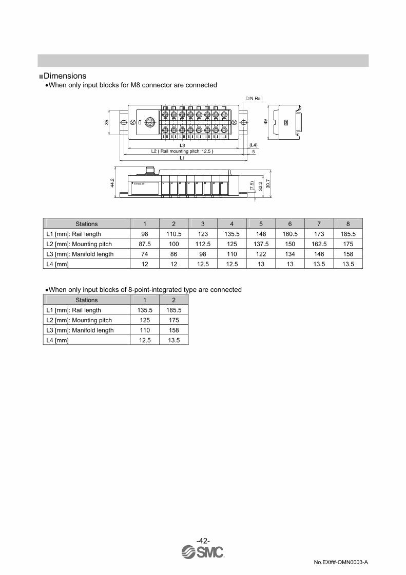
Dimensions
•When only input blocks for M8 connector are connected
Stations 1 2 3 4 5 6 7 8 L1 [mm]: Rail length 98 110.5 123 135.5 148 160.5 173 185.5 L2 [mm]: Mounting pitch 87.5 100 112.5 125 137.5 150 162.5 175 L3 [mm]: Manifold length 74 86 98 110 122 134 146 158 L4 [mm] 12 12 12.5 12.5 13 13 13.5 13.5
•When only input blocks of 8-point-integrated type are connected Stations 1 2
L1 [mm]: Rail length 135.5 185.5 L2 [mm]: Mounting pitch 125 175 L3 [mm]: Manifold length 110 158 L4 [mm] 12.5 13.5

-43-
No.EX##-OMN0003-A
•When only input blocks for M12 connector are connected
Stations 1 2 3 4 5 6 7 8 L1 [mm]: Rail length 110.5 123 148 173 185.5 210.5 223 248 L2 [mm]: Mounting pitch 100 112.5 137.5 162.5 175 200 212.5 237.5 L3 [mm]: Manifold length 82 102 122 142 162 182 202 222 L4 [mm] 12 12 12.5 12.5 13 13 13.5 13.5
-44-
No.EX##-OMN0003-A
EX9 Series General Purpose Output Block
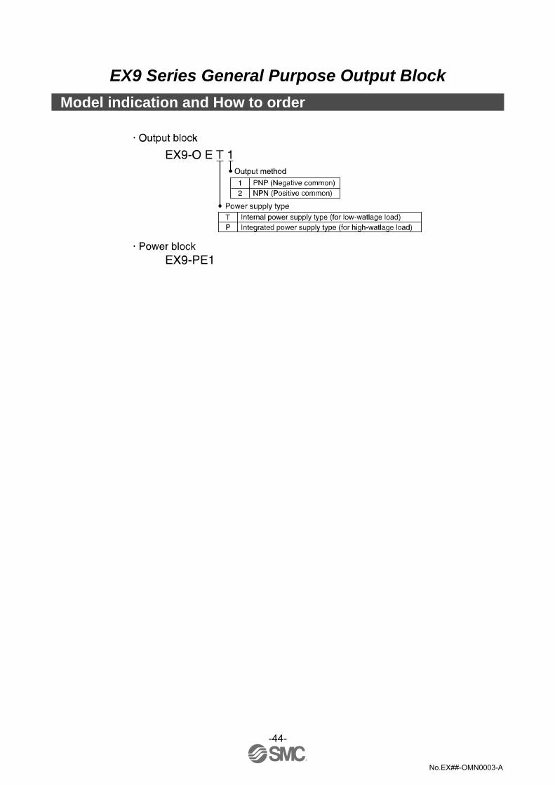
Model indication and How to order

-45-
No.EX##-OMN0003-A
Summary of Product parts The EX9 series general purpose output block is the unit to operate solenoid valve, relay, etc. in combination with SY/SV/VQC/S0700 series valve and applicable SI unit. There are two types ---- one type is for low wattage load (EX9-OET1 or EX9-OET2) that outputs signals by receiving power supply from SI unit, and the other type is for high wattage load (EX9-OEP1 or EX9-OEP2) that outputs signals by receiving power supply from outside. The type for high wattage load is used in combination with the power block (EX9-PE1) connected with external power supply. As the low-wattage-load type is powered from SI unit, the wattage of load is limited to 1.0 W 1. For a load up to 12 W, use the power block and the high-wattage-load type. For output block and power block specifications, refer to the manual. (EX##-OMH0005) 1. EX9-OET1/EX9-OET2/EX9-OEP1/EX9-OEP2
No. Description Function 1 Output connector Connects with output device. ∗1 2 Indicator LED Indicates the output status. ∗2
∗1: For wiring method, refer to subsection "Wiring" (page 47) of section "EX9 Series General Purpose Output Block" in this manual. ∗2: For display, refer to subsection "Setting" (page 49) of section "EX9 Series General Purpose Output Block" in this manual. 2. EX9-PE1
No. Description Function 1 Power supply connector Unused 2 Power input connector Supplies power for output devices. ∗1 3 Power LED Indicates the power supply status. ∗2
∗1: For wiring method, refer to subsection "Wiring" (page 47) of section "EX9 Series General Purpose Output Block" in this manual. ∗2: For display, refer to subsection "Setting" (page 49) in section "EX9 Series General Purpose Output Block" in this manual.
∗: When connecting it with the EX500 series

-46-
No.EX##-OMN0003-A
Mounting and Installation Installation
The mounting and removing methods of each SI unit are as shown below.
•Dimensions when general purpose output block is connected
L dimensions
No. of output blocks / power blocks stations
1 2 3 4 5 6 7 8
L1 [mm] 83 104 125 146 167 188 209 230 L2 [mm] 72 93 114 135 156 177 198 219 L3 [mm] 67 88 109 130 151 172 193 214
∗: The above dimensions show an example when one unit of power block (width: 21 mm) is combined.
NOTE Holding with hand so that there will be no gap between units and tighten the bolts. Be sure to tighten each bolt by specified tightening torque. (Tightening torque: 0.6 Nm)

-47-
No.EX##-OMN0003-A
Wiring
•Output wiring Connect output devices to the output connectors.
EX9-OET1/EX9-OET2/EX9-OEP1/EX9-OEP2 output connectors M12, 5-pin, socket
Model EX9-OET2/EX9-OEP2 EX9-OET1/EX9-OEP1 NPN output PNP output
No. Output connector No.0
Output connector No.1
Output connector No.0
Output connector No.1
1 Power supply (24 VDC) Power supply (24 VDC) N.C. N.C. 2 Output (OUT1) ∗ N.C. Output (OUT1) ∗ N.C. 3 N.C. N.C. Power supply (GND) Power supply (GND)4 Output (OUT0) Output (OUT1) Output (OUT0) Output (OUT1) 5 N.C. N.C. N.C. N.C.
N.C.: Not connected Two outputs are available with only output connector No. 0.
Pin alignment and connection drawing of the Output Cable
Pin No. Cable color 1 Brown 2 White 3 Blue 4 Black 5 Grey
NOTE Mount a waterproof cap to each unused connector. The proper use of waterproof cap can achieve IP65/67 Enclosure. (Tightening torque for M12: 0.1 Nm)

-48-
No.EX##-OMN0003-A
•Power supply wiring
When combining EX9-OEP1 (or EX9-OEP2) and EX9-PE1 and using external power supply, connect the power supply to the power input connector of EX9-PE1. When selecting power supply, refer to "Safety Instructions" (page 3) in this manual.
EX9-PE1 power supply connector No.0 M12, 5-pin, B-code (Reverse key), Socket
No. Description 1 Power supply for output devices (24 VDC) 2 Power supply for output devices (0 V) 3 [Power supply for sensor (24 VDC) ] 4 [Power supply for sensor (0 V) ] 5 Ground (FE)
∗: Keep the waterproof cap mounted on power supply connector No.0 while using EX9-PE1. This connector is prepared
supplementary and not used normally.
EX9-PE1 power input connector No.1 M12, 5-pin, B-code (Reverse key), plug
No. Description 1 Power supply for output devices (24 VDC) 2 Power supply for output devices (0 V) 3 [Power supply for sensor (24 VDC) ] 4 [Power supply for sensor (0 V) ] 5 Ground (FE)
∗: Each signal of connector No.0 is connected to corresponding signal of connector No.1. The pins whose applications are shown in brackets [ ], are prepared supplementary and not used normally.
Pin alignment and connection drawing of the Power Supply Cable
Pin No. Cable color: Signal name 1 Brown: Power supply for output (24 VDC) 2 White: Power supply for output (0 V) 3 Blue: [Power supply to sensor (24 VDC)] 4 Black: [Power supply to sensor (0 V)] 5 Grey: Ground (FE)
-49-
No.EX##-OMN0003-A
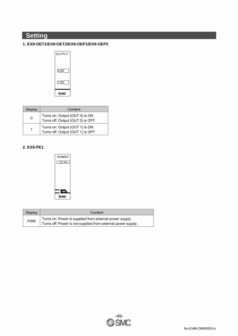
Setting 1. EX9-OET1/EX9-OET2/EX9-OEP1/EX9-OEP2
Display Content
0 Turns on: Output (OUT 0) is ON. Turns off: Output (OUT 0) is OFF.
1 Turns on: Output (OUT 1) is ON. Turns off: Output (OUT 1) is OFF.
2. EX9-PE1
Display Content
PWR Turns on: Power is supplied from external power supply. Turns off: Power is not supplied from external power supply.

-50-
No.EX##-OMN0003-A
Specification Specifications 1. EX9-OET1/EX9-OET2/EX9-OEP1/EX9-OEP2
Item Specification Model No. EX9-OET1 EX9-OET2 EX9-OEP1 EX9-OEP2
No. of output points 2 points/unit
Output type PNP (Negative
common) NPN (Positive
common) PNP (Negative
common) NPN (Positive
common)
Insulation method Optical isolation (with SI unit) Optical isolation (with this unit) (Note)
∗: To be used in combination with EX9-PE1. 2. EX9-PE1
Item Specification Rated voltage 24 VDC+10%/-5% Supply current 3 A Max.

-51-
No.EX##-OMN0003-A
Dimensions
1. EX9-OET1/EX9-OET2/EX9-OEP1/EX9-OEP2
2. EX9-PE1

-52-
No.EX##-OMN0003-A
Troubleshooting Troubleshooting flow chart When any fieldbus system failure occurs, perform the following troubleshooting procedure:-
Yes
No
The fieldbus system does not work correctly
GW unit MS LED is red ON
GW unit MS LED is OFF
Refer to fault No. 1
Refer to fault No. 2
Refer to fault No. 3
GW unit MS LED is red flashing
Check the state of the GW unit
Refer to fault No. 4
GW unit MS LED is green flashing
Refer to fault No. 5
Refer to fault No. 6
Refer to fault No. 7
Refer to fault No. 8
Refer to fault No. 9
GW unit NS LED is OFF
GW unit NS LED is red
flashing
GW unit NS LED is red ON
GW unit NS LED is green
flashing
GW unit PWR LED is OFF

-53-
No.EX##-OMN0003-A
Output block does not operate correctly, output block
LED is OFF
Check the state of the solenoid valve
SI unit communication
LED is OFF
The solenoid valves after Output 17 do not
operate
Refer to fault No. 11
Refer to fault No. 12
Refer to fault No. 13
Refer to fault No. 10
Refer to fault No. 14
The solenoid valve and the output block do not
operate correctly.
SI unit power supply LED is OFF
Solenoid valves do not operate correctly, solenoid
valve LED is OFF
Solenoid valves do not operate correctly, solenoid
valve LED is ON.
Output block does not operate correctly, output block
LED is ON
Refer to fault No. 15
Refer to fault No. 16
Check the state of the output block
-54-
No.EX##-OMN0003-A
Input device data cannot be recognized
Input unit power supply LED is OFF
Input unit power supply LED is
flashing
Corresponding GW unit COM∗LED is
OFF
The solenoid valves after Input 17 do not
operate
Input block LED does not turn ON
Input block LED and the input data do not
match
Refer to fault No. 17
Refer to fault No. 18
Refer to fault No. 19
Refer to fault No. 20
Refer to fault No. 21
Refer to fault No. 22

-55-
No.EX##-OMN0003-A
Cross-reference for troubleshooting
Fault No. 1 Problem Possible cause Investigation method Countermeasures
Tighten the power supply cable connection. (If the cable has a broken wire, replace the cable).
Defective wiring of the power supply for input and control
Check the power supply cable connections and check for broken wires.
Rectify the wiring of the power supply cable.
GW unit MS LED is OFF
Incorrect power supply for input and control
Check the supply voltage for input and control.
Supply 24 VDC ±10% to the power supply for the GW unit control.
Fault No. 2 Problem Possible cause Investigation method Countermeasures
GW unit MS LED is red ON
Malfunction of the GW unit
Change the GW unit and then check whether it is improved or not.
Same as left.
Fault No. 3 Problem Possible cause Investigation method Countermeasures
GW unit MS LED is red flashing
Incomplete network configuration
Check the settings of the EtherNet/IPTM master.
Complete the configuration of the master.
Fault No. 4 Problem Possible cause Investigation method Countermeasures
GW unit MS LED is green flashing
Incomplete network configuration
Check the settings of the EtherNet/IPTM master.
Complete the configuration of the master.
Fault No. 5 Problem Possible cause Investigation method Countermeasures
Re-tighten the power cable. (Replace the cable if it is broken).
Incorrect wiring of the power supply for input and control
Check the power supply cable connections and check for broken wires.
Correct the power cable wiring layout
Incorrect power supply for input and control
Check the supply voltage to the power supply for the input and control.
Supply 24 VDC ±10% to the power supply for the input and control.
GW unit NS LED is OFF
No IP address Wait for the IP address to be set by the DHCP server
Set the IP address using the DHCP server.
-56-
No.EX##-OMN0003-A
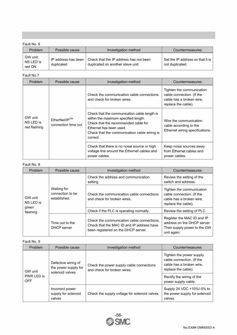
Fault No. 6
Problem Possible cause Investigation method Countermeasures
GW unit NS LED is red ON
IP address has been duplicated
Check that the IP address has not been duplicated on another slave unit.
Set the IP address so that it is not duplicated.
Fault No.7
Problem Possible cause Investigation method Countermeasures
Check the communication cable connections and check for broken wires.
Tighten the communication cable connection. (If the cable has a broken wire, replace the cable).
Check that the communication cable length is within the maximum specified length. Check that the recommended cable for Ethernet has been used. Check that the communication cable wiring is correct.
Wire the communication cable according to the Ethernet wiring specifications.
GW unit NS LED is red flashing
EtherNet/IPTM connection time out
Check that there is no noise source or high voltage line around the Ethernet cables and power cables.
Keep noise sources away from Ethernet cables and power cables.
Fault No. 8 Problem Possible cause Investigation method Countermeasures
Check the address and communication setting.
Review the setting of the switch and address.
Check the communication cable connections and check for broken wires.
Tighten the communication cable connection. (If the cable has a broken wire, replace the cable).
Waiting for connection to be established.
Check if the PLC is operating normally. Review the setting of PLC.
GW unit NS LED is green flashing
Time out to the DHCP server
Check the communication cable connections.Check that the MAC ID and IP address have been registered on the DHCP server.
Register the MAC ID and IP address on the DHCP server. Then supply power to the GW unit again.
Fault No. 9 Problem Possible cause Investigation method Countermeasures
Tighten the power supply cable connection. (If the cable has a broken wire, replace the cable).
Defective wiring of the power supply for solenoid valves
Check the power supply cable connections and check for broken wires.
Rectify the wiring of the power supply cable.
GW unit PWR LED is OFF
Incorrect power supply for solenoid valves
Check the supply voltage for solenoid valves.Supply 24 VDC +10%/-5% to the power supply for solenoid valves.

-57-
No.EX##-OMN0003-A
Fault No. 10
Problem Possible cause Investigation method Countermeasures
SI unit power supply LED is OFF
Defective wiring of the power supply for input and control
Check the branch cable connections and check for broken wires.
Tighten the branch cable connection. (If the cable has a broken wire, replace the cable).
Fault No. 11 Problem Possible cause Investigation method Countermeasures
Check the branch cable connections and check for broken wires.
Tighten the branch cable connection. (If the cable has a broken wire, replace the cable).
Check the wiring length of the local bus cable and check that the recommended cable is used.
Review the wiring to make the wire length between the GW unit and SI unit 5 m maximum. Make the wire length between the SI unit and input unit 5 m maximum. Recommended SMC cable: EX500-AC∗∗∗-S∗P∗
SI unit communication LED is OFF
Communication failure of the EX500 local bus
Check that there is no high voltage cable or equipment that generates noise around the local bus cable.
Separate the local bus cable away from noise sources.
Fault No.12 Problem Possible cause Investigation method Countermeasures
The solenoid valves after Output 17 do not operate
The total number of output devices (solenoid valves and output blocks) for one port of the GW unit should be 16 maximum
Check the total number of output devices. Remove the excessive output devices.
-58-
No.EX##-OMN0003-A
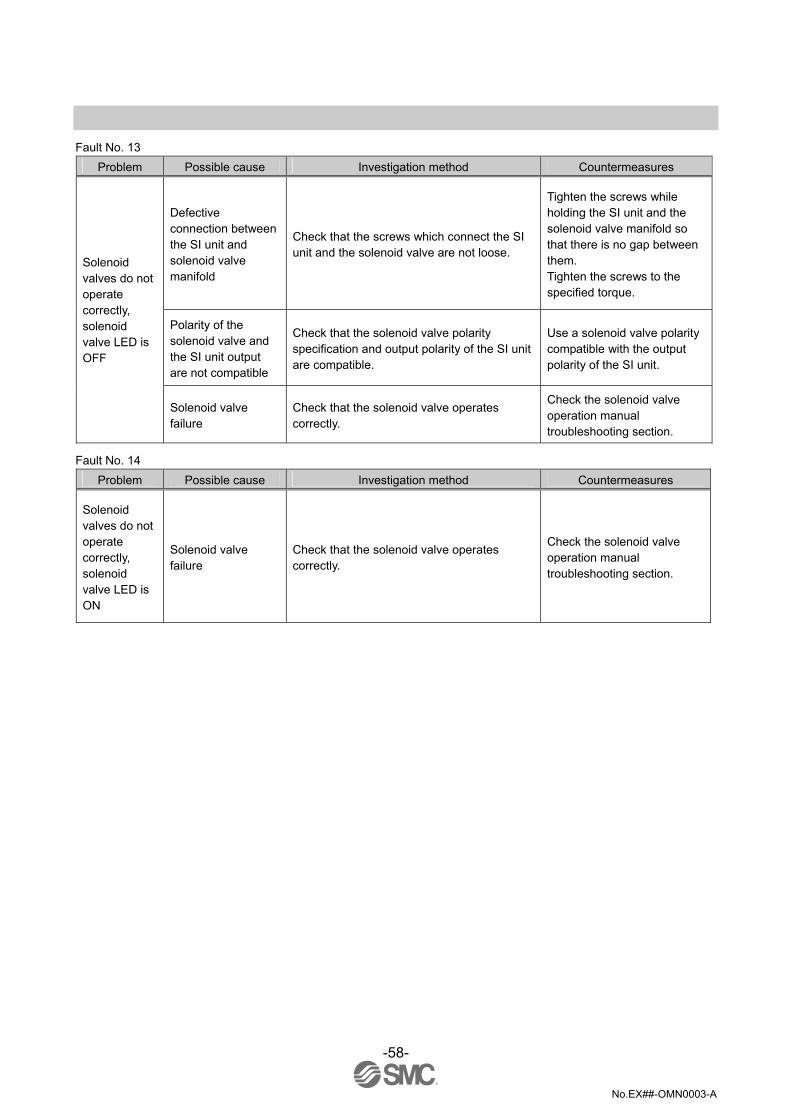
Fault No. 13
Problem Possible cause Investigation method Countermeasures
Defective connection between the SI unit and solenoid valve manifold
Check that the screws which connect the SI unit and the solenoid valve are not loose.
Tighten the screws while holding the SI unit and the solenoid valve manifold so that there is no gap between them. Tighten the screws to the specified torque.
Polarity of the solenoid valve and the SI unit output are not compatible
Check that the solenoid valve polarity specification and output polarity of the SI unit are compatible.
Use a solenoid valve polarity compatible with the output polarity of the SI unit.
Solenoid valves do not operate correctly, solenoid valve LED is OFF
Solenoid valve failure
Check that the solenoid valve operates correctly.
Check the solenoid valve operation manual troubleshooting section.
Fault No. 14 Problem Possible cause Investigation method Countermeasures
Solenoid valves do not operate correctly, solenoid valve LED is ON
Solenoid valve failure
Check that the solenoid valve operates correctly.
Check the solenoid valve operation manual troubleshooting section.

-59-
No.EX##-OMN0003-A
Fault No. 15
Problem Possible cause Investigation method Countermeasures
Defective connection between the SI unit and output block
Check that the screws which connect the SI unit and output block are not loose.
Tighten the screws while holding the SI unit and the output block so that there is no gap between them. Tighten the screws to the specified torque.
Polarity of the output block and SI unit output are not compatible
Check that the output block polarity specification and output polarity of the SI unit are compatible. •EX500-Q002 (NPN output) ⇔EX9-OET2/-OEP2 •EX500-Q102 (PNP output) ⇔EX9-OET1/-OEP1
Use an output block polarity compatible with the output polarity of the SI unit.
Defective connection of the power block (when using EX9-OEP1/-OEP2)
Check if a power block is used, and check that the position of the power block is correct.
Install the power block on the SI unit side of the output block (EX9-OEP1/-OEP2). Refer to the operation manual of EX9 series general purpose output block).
Output block does not operate correctly, output block LED is OFF
Failure of power block or output block
Check that the power block and output block are operating correctly.
Replace the power block or output block and check the operation.
Fault No. 16 Problem Possible cause Investigation method Countermeasures
Tighten the cable connection. (If the cable has a broken wire, replace the cable).
Defective connection between the output block and load device
Check the connection and wiring (pin layout) between the load device and the output block.Check for broken wires. Rectify the wiring of the load
device cable.
Output block does not operate correctly, output block LED is ON
Output block failure Check that the output block is operating correctly.
Replace the output block and check the operation.
Fault No. 17 Problem Possible cause Investigation method Countermeasures
Input unit power supply LED is OFF
Defective wiring of the power supply for input and control
Check the branch cable connections and check for broken wires.
Tighten the branch cable connection. (If the cable has a broken wire, replace the cable).

-60-
No.EX##-OMN0003-A
Fault No. 18
Problem Possible cause Investigation method Countermeasures
Ensure that the total current consumption is within the specified range of the input unit.
Check the total current consumption of the input devices used.
Resolve the short-circuit or over current.
Over current power supply for input and control
Check the input devices used, and check the wiring to the input devices.
Input unit power supply LED is flashing
Power supply short-circuit of the input devices used
Check that the input device is operating correctly.
Refer to the input device operation manual troubleshooting section, or contact the input device manufacturer.
Fault No. 19
Problem Possible cause Investigation method Countermeasures
Check the branch cable connections and check for broken wires.
Tighten the branch cable connection. (If the cable has a broken wire, replace the cable).
Check the wiring length of the local bus cable and that the recommended cable is used.
Review the wiring to make the wire length between the GW unit and SI unit 5 m maximum. Make the wire length between the SI unit and input unit 5 m maximum. Recommended SMC cable: EX500-AC∗∗∗-S∗P∗
Check that the input unit used is correct. Use the correct type of input unit.
Corresponding GW unit COM∗LED is OFF
Communication failure of the EX500 local bus
Check that there is no high voltage cable or equipment that generates noise around the local bus cable.
Separate the local bus cable away from noise sources.
Fault No. 20 Problem Possible cause Investigation method Countermeasures
The solenoid valves after Input 17 do not operate
The total number of inputs for one port of the GW unit should be 16 maximum.
Check the total number of input blocks. Remove the excessive input blocks.
-61-
No.EX##-OMN0003-A
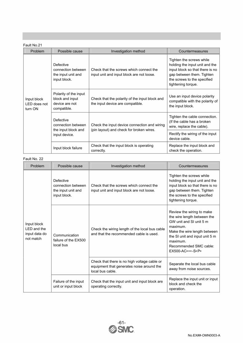
Fault No.21
Problem Possible cause Investigation method Countermeasures
Defective connection between the input unit and input block.
Check that the screws which connect the input unit and input block are not loose.
Tighten the screws while holding the input unit and the input block so that there is no gap between them. Tighten the screws to the specified tightening torque.
Polarity of the input block and input device are not compatible.
Check that the polarity of the input block and the input device are compatible.
Use an input device polarity compatible with the polarity of the input block.
Tighten the cable connection. (If the cable has a broken wire, replace the cable).
Defective connection between the input block and input device.
Check the input device connection and wiring (pin layout) and check for broken wires.
Rectify the wiring of the input device cable.
Input block LED does not turn ON
Input block failure Check that the input block is operating correctly.
Replace the input block and check the operation.
Fault No. 22
Problem Possible cause Investigation method Countermeasures
Defective connection between the input unit and input block.
Check that the screws which connect the input unit and input block are not loose.
Tighten the screws while holding the input unit and the input block so that there is no gap between them. Tighten the screws to the specified tightening torque.
Check the wiring length of the local bus cable and that the recommended cable is used.
Review the wiring to make the wire length between the GW unit and SI unit 5 m maximum. Make the wire length between the SI unit and input unit 5 m maximum. Recommended SMC cable: EX500-AC∗∗∗-S∗P∗
Communication failure of the EX500 local bus
Check that there is no high voltage cable or equipment that generates noise around the local bus cable.
Separate the local bus cable away from noise sources.
Input block LED and the input data do not match
Failure of the input unit or input block
Check that the input unit and input block are operating correctly.
Replace the input unit or input block and check the operation.

-62-
No.EX##-OMN0003-A
Option 1. Communication cable for Ethernet For details, refer to subsection "Wiring" (page 10) in section "EX500 GW unit" in this
manual.
2. Fieldwireable connector for Ethernet For details, refer to subsection "Wiring" (page 10) in section "EX500 GW unit" in this
manual.
3 Branch cable with M12 connector For details, refer to subsection "Wiring" (page 10) in section "EX500 GW unit" in this
manual.
4 Power supply connector cable For details, refer to subsection "Wiring" (page 10) of section "EX500 GW unit" in this manual.
5 Output cable For details, refer to subsection "Wiring" (page 47) of section "EX9 series General Purpose Output Block " in this
manual.
-63-
No.EX##-OMN0003-A
6 Power supply connector cable For details, refer to subsection "Wiring" (page 47) of section "EX9 series General Purpose
Output Block " in this manual.
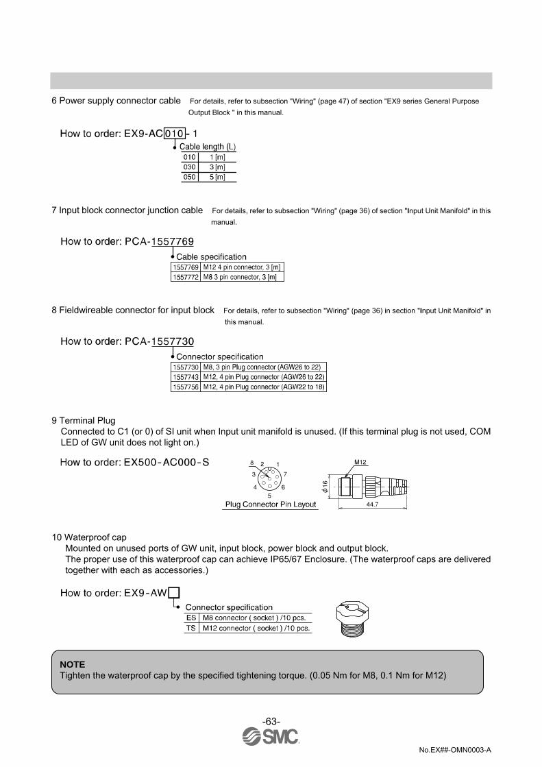
7 Input block connector junction cable For details, refer to subsection "Wiring" (page 36) of section "Input Unit Manifold" in this
manual.
8 Fieldwireable connector for input block For details, refer to subsection "Wiring" (page 36) in section "Input Unit Manifold" in
this manual.
9 Terminal Plug
Connected to C1 (or 0) of SI unit when Input unit manifold is unused. (If this terminal plug is not used, COM LED of GW unit does not light on.)
10 Waterproof cap
Mounted on unused ports of GW unit, input block, power block and output block. The proper use of this waterproof cap can achieve IP65/67 Enclosure. (The waterproof caps are delivered together with each as accessories.)
NOTE Tighten the waterproof cap by the specified tightening torque. (0.05 Nm for M8, 0.1 Nm for M12)

No.EX##-OMN0003-A
Revision history A: Contents revised in several places.
Note: Specifications are subject to change without prior notice and any obligation on the part of the manufacturer. EtherNet/IPTM is a trademark of ODVA. © 2011 SMC Corporation All Rights Reserved


