EU HARMONISED TEST PROTOCOLS FOR PEMFC MEA TESTING IN SINGLE CELL CONFIGURATION FOR AUTOMOTIVE APPLICATIONS 2015 Georgios Tsotridis, Alberto Pilenga, Giancarlo De Marco, Thomas Malkow EUR 27632 EN
Transcript
EU HARMONISED TEST PROTOCOLS FOR PEMFC MEA TESTING IN SINGLE CELL CONFIGURATION FOR AUTOMOTIVE APPLICATIONS
2015
Georgios Tsotridis, Alberto Pilenga, Giancarlo De Marco, Thomas Malkow
EUR 27632 EN
This publication is a Science for Policy report by the Joint Research Centre, the European Commission’s in-house
science service. It aims to provide evidence-based scientific support to the European policy-making process.
The scientific output expressed does not imply a policy position of the European Commission. Neither the
European Commission nor any person acting on behalf of the Commission is responsible for the use which might
be made of this publication.
JRC Science Hub
https://ec.europa.eu/jrc
JRC99115
EUR 27632 EN
PDF ISBN 978-92-79-54132-2 ISSN 1831-9424 doi: 10.2790/54653 LD-NA-27632-EN-N
Print ISBN 978-92-79-54133-9 ISSN 1018-5593 doi: 10.2790/342959 LD-NA-27632-EN-C
APPENDIX G: MEA SPECIFICATION ..................................................................... 59
EU Harmonised Test Protocols for PEMFC-MEA Testing in Single Cell Configuration for Automotive Applications
VI
THIS PAGE IS LEFT BLANK INTENTIONALLY
EU Harmonised Test Protocols for PEMFC-MEA Testing in Single Cell Configuration for Automotive Applications
VII
LIST OF CONTRIBUTORS
(in alphabetical order of their organisations)
Automotive Fuel Cell Cooperation
Robert Boulianne
Bayerische MotorenWerke Aktiengesellschaft
Johannes Schmid
Zacharias Veziridis
Peter Wilde
CEA Commissariat à l'énergie atomique et aux énergies alternatives
Pierre-André Jacques
Daimler Aktiengesellschaft Georg Frank
Martin Heinen
Deutsches Zentrum für Luft- und Raumfahrt e. V.
Andreas Friedrich
Jens Mitzel
Mathias Schulze
Fraunhofer ISE Ulf Groos
FuMA-Tech Gesellschaft für funktionelle Membranen und Anlagentechnologie mbH
Tomas Klicpera
IRD fuel cell A/S Madeleine Odgaard
Johnson Matthey Fuel Cells Ltd Silvain Buche
Technische Universität München
Oliver Schneider
Toyota Motor Europe Isotta Cerri
Université de Montpellier Deborah Jones
Volkswagen Aktiengesellschaft Gerold Hübner
Miriam Stiefel
Zentrum für Sonnenenergie- und Wasserstoff-Forschung BW
Ludwig Jörissen
Alexander Kabza
EU Harmonised Test Protocols for PEMFC-MEA Testing in Single Cell Configuration for Automotive Applications
VIII
THIS PAGE IS LEFT BLANK INTENTIONALLY
EU Harmonised Test Protocols for PEMFC-MEA Testing in Single Cell Configuration for Automotive Applications
IX
ACKNOWLEDGEMENTS
These harmonised testing protocols are the result of a collaborative effort between industry partners and research organisations participating in several Fuel Cell and Hydrogen Joint Undertaking funded projects in automotive applications.
We would like to express our sincere gratitude to all participants and their respective organisations for their contributions in developing these harmonised testing protocols. We would also like to thank the Fuel Cell and Hydrogen Joint Undertaking Programme Office for the continuous support and encouragement we received throughout the different stages of this activity.
Last but not least we would like to thank our colleagues at the Institute for Energy and Transport of the Joint Research Centre for their continuous support throughout the different stages of this effort.
EU Harmonised Test Protocols for PEMFC-MEA Testing in Single Cell Configuration for Automotive Applications
X
THIS PAGE IS LEFT BLANK INTENTIONALLY
EU Harmonised Test Protocols for PEMFC-MEA Testing in Single Cell Configuration for Automotive Applications
XI
EXECUTIVE SUMMARY
Proton Exchange Fuel Cells due to their high energy density, low operating temperature and high efficiency are considered to be very suitable for vehicle propulsion. In such applications, fuel cells could encounter operating conditions which are severe to the materials involved. Fuel cell testing shall as close as possible reflect conditions encountered in real life. To enable a fair comparative assessment of the performance of membrane electrode assemblies (MEA) under operating conditions foreseen in future automotive applications, a set of representative operating conditions in addition with a test methodology is proposed. The aim of a unified set of harmonised operating conditions is to comparatively test and evaluate the performance of different MEAs in single cells. The current document is the result of a cumulative effort of industry and research organisations participating in Fuel Cell and Hydrogen Joint Undertaking funded projects for automotive applications, in establishing a harmonised test protocol for assessing PEM fuel cell performance and durability at a single cell level. This document presents a set of reference operating conditions such as temperature, pressure, humidification, gas flow and composition at the fuel and oxidant inlet representative for future automotive applications. It also defines boundaries of these conditions within which the cell is expected to operate. While not specifying single cell design details, cell operation in counter flow is mandatory for comparative assessment. A methodology is established to examining the relative influence that the individual operating parameters exert on the MEA performance in single cell configuration once the cell is subjected to the more challenging boundary conditions defined in this document which are also called as “stressor conditions”. In addition to “operating conditions”, the most likely stressor conditions for single cell testing could be identified as follows:
In this document the focus is on stressors related to “Operating Conditions” and “Load Cycling”. Deviations from the automotive reference “Operating Conditions” may result in changes to both cell performance and durability. In principle the influence of each stressor on cell performance could be studied individually. However, since a number of stressors are inter-linked, (changing the value of one stressor could inevitably change the value of another), the stressor tests have been grouped into four families of Stressors, namely: • Cell Temperature Stressor Tests • Reactants Gas Inlet Humidification Stressor Tests • Reactants Gas Inlet Pressure Stressor Tests • Oxidant Stoichiometry Stressor Tests
EU Harmonised Test Protocols for PEMFC-MEA Testing in Single Cell Configuration for Automotive Applications
XII
The aim of these tests is to study the effect of each stressor on the the cell voltage at three different current densities representative of activation, ohmic polarization and mass transfer regimes as a function of each stressor condition. The successful operation of a fuel cell depends not only on its performance but also on its durability. Fuel cell durability is evaluated through endurance testing by applying a repetitive load profile to the cell and measuring performance degradation in terms of cell voltage decrease as function of operating hours. To assess the cell degradation rate a dynamic load cycle for endurance testing is proposed. The Fuel Cell Dynamic Load Cycle, (FC-DLC) is used in this document and is derived from the New European Driving Cycle (NEDC) modified for fuel cell applications.
In addition to the definition of representative “reference” and “stressor operating conditions”, the document also provides a rationale for their selection. The use of sound science-based, industry-endorsed test methodologies and protocols enables true comparison of MEAs originating from different sources either commercial or developed within different projects. It also enables evaluating the rate of progress achieved towards reaching agreed technology performance targets.
EU Harmonised Test Protocols for PEMFC-MEA Testing in Single Cell Configuration for Automotive Applications
1
1. INTRODUCTION
The European Union’s transport sector is the second largest energy consumer in Europe being responsible for 33% of the total energy consumption and about 25% of the total European greenhouse gas emissions (GHG) emissions. The European Union is committed to transforming its transport and energy sector as part of a future low carbon economy. It has been agreed to define binding targets to cut greenhouse gas emissions from the transport sector by at least 60% below the 1990 levels by 2050.
For reducing emissions, the EU has put into place a “Competitive low-carbon energy” action which supports this transition by addressing the whole innovation process including non-technological issues such as standardisation, social sciences and humanities, impact analysis, etc., covering a wide range of technologies, combining research and development with market uptake. The use of alternative fuels to reducing emissions and petroleum dependency is therefore urgently required.
It is recognised that Fuel Cell and hydrogen technologies hold great promise for energy and transport applications from the perspective of meeting Europe’s energy, environmental and economic goals and are part of the Strategic Energy Technologies (SET) Plan - , which was adopted by the European Union in 2008.
In addition, comprehensive Research and Innovation (R&I) actions are also necessary to support hydrogen and fuel cell technologies and in that respect the public-private partnership on Fuel Cells and Hydrogen (FCH-JU) plays a central role. The development and harmonisation of regulations, codes and standards supports the introduction of these new technologies into the market. To this end, the FCH-JU has funded a number of projects that individually addressed the development and performance of materials in single fuel cells, and in stacks for automotive applications.
The objective of this document is to present a set of harmonised operating
conditions, testing protocols and procedures for assessing both performance and
durability of Polymer Electrolyte or Proton Exchange Membrane Fuel Cells (PEMFCs) in Single Cell configuration for automotive applications to allow fair comparison of test results from various projects and laboratories.
The methodology adopted in this document reflects the processes which are followed in the development towards improving the performance and durability of fuel cell materials and single cells relevant for automotive applications. The development sequence which is normally followed in practice consists of four distinct steps, namely: Development of Materials, Single Cells, Stacks and Systems, Fig 1.
EU Harmonised Test Protocols for PEMFC-MEA Testing in Single Cell Configuration for Automotive Applications
2
Figure 1: Schematic of the process chain for fuel cell development
The development of Materials entails R&D of new materials such as membranes, gas diffusion layers and catalysts based on a variety of innovative methods, processes and manufacturing techniques. Once these new materials and components have been developed they are then "screened" in-situ or ex-situ for their potential use as candidate materials for the Membrane Electrode Assemblies (MEAs) which in turn are subjected to further systematic screening most often in single cell test configurations to identifying the most promising MEAs with enhanced performance and durability. These MEAs are eventually considered as potential candidates for use in automotive stacks.
Stack and system development requires extensive testing, under real world conditions, however the test results are normally confidential.
This report is the result of a joint effort by several mainly European interested parties, such as Original Equipment Manufacturers, (OEMs), fuel cell material
manufacturers and various research establishments active in automotive fuel cell
Research & Development which on a voluntary basis agreed to define a set of harmonized operating conditions and testing protocols for performing characterization of MEA in Single Fuel Cell Configuration for automotive
applications.
This report could be revised in the future to accommodate new ideas and developments.
Materials
MEA Testing in Single
Cells Stacks Systems
EU Harmonised Test Protocols for PEMFC-MEA Testing in Single Cell Configuration for Automotive Applications
3
2. AUTOMOTIVE REFERENCE OPERATING CONDITIONS
Fuel cells for automotive applications could operate under a variety of conditions, some of them being severe to the involved materials. The aim of a unified set of operation conditions is to test and evaluate the performance of different MEAs in single cell testing hardware and provide an opportunity of a fair comparison. The reference operating conditions should reflect conditions most likely to be found in future passenger vehicle applications.
It was agreed that a counter-flow configuration between anode and cathode side for the gas supply should be used for an even distribution of the reactants (fuel and oxidant) across the electrode areas. Co-flow and cross-flow configurations have been excluded since generally they are not used in automotive applications. The tests are carried out in open end mode (i.e. surplus fuel and oxidant are vented).
The reference conditions specify all typical PEM fuel cell operating parameters, such as: temperatures, pressures and gas compositions at the fuel and oxidant inlets as well as the operating temperature of the fuel cell. The inlet flows of reactants are kept in stoichiometric regime.
These conditions are:
2.1 CELL TEMPERATURE
The reference cell temperature value of 80°C has been chosen as being a representative cell temperature for automotive applications. The cell temperature is measured at the centre point of the cathode monopolar plate of the single cell test hardware
and is to be maintained by the most appropriate technique, i.e. by electric heaters placed on both sides of the fuel cell, or by a liquid heating/cooling exchange system.
2.2 ANODE CONDITIONS
Fuel gas inlet temperature
The fuel gas temperature at the inlet is kept 5 K above the cell operating temperature to prevent water condensation at the cell inlet.
Fuel gas inlet humidity
Since in automotive applications hydrogen as fuel is normally used in recirculation mode, the reference fuel humidity should refer to the conditions of a typical hydrogen recirculation system used in vehicles which corresponds to mixing dry hydrogen supplied from the fuel tank and humidified hydrogen from the recirculation system. During fuel cell operation, water is always produced at the cathode compartment and is partially transported by back-diffusion to the anode. It is suggested to consider at the anode inlet
EU Harmonised Test Protocols for PEMFC-MEA Testing in Single Cell Configuration for Automotive Applications
4
a nominal value of Relative Humidity (RH) corresponding to 50% with respect to the cell temperature which in turn corresponds to a dew point of 64°C for a cell temperature of 80°C, see Appendix A.
Fuel inlet pressure
Typically test benches have controlled back pressure valves positioned near the cell outlet in the exhaust gas stream. Therefore pressure regulation is normally performed at cell outlet.
However it was agreed to keep constant the inlet pressure by controlling the back pressure valves to minimising pressure changes related to fluctuations caused by gas flow and pressure drop. In Figure 2 such a pressure control strategy at anode and cathode is presented for the fuel and oxidant respectively. The pressure signal p.Si.A and p.Si.C measured from the pressure transducers PI1 and PI2 in Fig.2 is used to regulate the backpressure p.PC.A and p.PC.C.
The proposed pressure value was chosen by taking into account mass transfer phenomena and water management issues. The absolute pressure of 250 kPa at the anode inlet p.Si.A is considered as a typical value in automotive applications to ensure a high power density.
Figure 2 Reactant pressure control strategy scheme with reactant counter flow
configuration
Fuel composition
The fuel composition should assure a low level of impurities (contaminants), due to the susceptibility of Pt metal catalyst of being poisoned by contaminants levels. For this reason the hydrogen fuel used should be of quality 5.0 or better.
It is has been suggested[19,20] that the hydrogen supplied in gas cylinders with quality grade 5.0 does not influence the performance and the lifetime of laboratory tested MEAs.
Anode inlet
Cathodeinlet
Anode Outlet
CathodeOutlet
p.PC.A
p.PC.C
PI2
PI1
EU Harmonised Test Protocols for PEMFC-MEA Testing in Single Cell Configuration for Automotive Applications
5
The fuel quality shall have no measurable impact on both performance and lifetime of the MEA. Critical constituents that need to be avoided are H2S (or other sulphur compounds), CO, CO2 and NH3.
Fuel (hydrogen) stoichiometry
The fuel inlet flow rate corresponds to electro-chemical fuel cell reaction stoichiometry with λ=1.3. In case of current densities below 0.2 A.cm-2 the minimum flow rate is kept fixed at the value corresponding to 0.2 A.cm-2 for a stoichiometry of λ=1.3.
Such stoichiometry requires using bipolar plates with a relatively high value of pressure drop, at least greater than 1 kPa.m-1 at 0.8 A.cm-2, to favour the transport of the water droplets along the channels.
2.3 CATHODE CONDITIONS
Oxidant gas inlet temperature
The oxidant temperature (air or oxygen) at the inlet is kept 5 K above the cell temperature to prevent condensation of water at cell inlet.
Oxidant gas inlet relative humidity
Since the oxidant flow is typically air from ambient, its relative humidity may widely vary as a function of ambient conditions. The oxidant gas inlet relative humidity in the cathode compartment is set to 30% with reference to the cell temperature, for simulating rather dry test environment conditions.
For details concerning the relative humidity and dew point temperature see Appendix A
Oxidant inlet pressure
Many test benches have controlled back pressure valves, therefore the pressure control approach for the oxidant is the same as for the fuel pressure control (see Figure 2). The proposed absolute pressure value of 230 kPa has been chosen to sufficiently facilitate mass transfer, hence adequate water management.
Oxidant composition
Oxidant composition should assure a low level of impurities (contaminants) as Pt metal catalyst is sensitive to specific contaminants at the cathode. For testing purposes the oxidant (air) should be oil free and filtered for dust particulates according to ISO 8573-1:2010 with
EU Harmonised Test Protocols for PEMFC-MEA Testing in Single Cell Configuration for Automotive Applications
6
The air quality shall have no measurable impact on both performance and lifetime of the MEA. As long as oil free compressed ambient air (instead of high quality bottled air) is used, the critical constituents that need to be avoided are SOx, NOx, and NH3.
Oxidant (air) stoichiometry
The cathode inlet flowrate corresponds to electro-chemical fuel cell reaction stoichiometry with λ=1.5. In case of current densities below 0.2 A cm-2 the minimum flow rate is kept fixed at the value corresponding to 0.2 A.cm-2 for a stoichiometry of λ=1.5. The stoichiometry value λ=1.5 was agreed for keeping the power requirements for the air compressor at a minimum.
The fuel stoichiometry comments concerning the gas channel bipolar plate design are also applicable to the oxidant side, plates with a value of pressure drop, at least greater than 10 kPa.m-1 at 0.8 A.cm-2, to favour the transport of the water droplets along the channels.
Table 1 presents the agreed Automotive Reference Operating Conditions:
EU Harmonised Test Protocols for PEMFC-MEA Testing in Single Cell Configuration for Automotive Applications
7
TABLE 1
EU Harmonised Automotive Reference Operating Conditions for Low
Temperature PEFC single cell testing at open end mode and in counter-
flow configuration
Parameters Symbol Unit Values
Nominal cell operating temperature
T.Si,CL °C 80
AN
OD
E
Fuel gas inlet temperature T.Si.A °C 85
Fuel gas inlet humidity
RH.Si.A
DPT.Si.A
% RH
°C
50
64
@80°C
Fuel gas inlet pressure (absolute)
p.Si.A kPa 250
Fuel gas composition Conc.Si.A.H2, Conc.Si.A.GasX
According to H2
5.0 quality
Fuel stoichiometry Stoic.Si.A - 1.3
CA
TH
OD
E
Oxidant gas inlet temperature T.Si.C °C 85
Oxidant gas inlet humidity
RH.Si.C
DPT.Si.C
% RH
°C
30
53
@80°C
Oxidant gas inlet
pressure (absolute) p.Si.C kPa 230
Oxidant Conc.Si.C.O2, Conc.Si.C.GasX
-
According to ISO 8573-1:2010
Air stoichiometry Stoic.Si.C - 1.5
Minimum current density for stoichiometry operation
I.S.MinGasFlow A/cm2
0.2
EU Harmonised Test Protocols for PEMFC-MEA Testing in Single Cell Configuration for Automotive Applications
8
3 STRESSOR TESTS
In this approach a methodology is established to examining the relative influence that various parameters exert on the performance of the MEA in single cell configuration when the cell is subjected to conditions deviating from the “normal operating
settings”. These conditions are hereinafter called “stressor conditions”.
The most likely stressor conditions for single cell testing could be identified based on:
Operating Conditions;
A higher or lower variation from the reference automotive operating conditions could be considered as a “stressor” condition. For single cell testing two settings one High and one Low have been defined as contributing stress factors.
Mechanical Effects;
Stressors due to mechanical effects have a direct consequence on the cell performance. The compression force applied to the cell is normally considered as a mechanical stressor, and the reference value should be mentioned with the test results. This stressor is fixed at the beginning of the test and it will not be further considered in this approach.
Mechanical stresses could also arise due to frequent humidity, pressure and/or temperature cycling as well as due to significant acceleration and deceleration forces and strains when applied. The latter possibilities are not within the scope of this approach. They may however be likely of most relevance to stacks.
Load Cycling;
Load cycling to simulating varying power demands during vehicle operation is another external source of stress on MEA performance in single cell configuration. Start-up and stop cycles are an additional stress factor for the MEA. The purpose of these cycles is to assess long term durability of the MEA in automotive applications.
• Fuel / air impurities (contaminants)
Although this is an important issue it will not be addressed in the current methodology.
EU Harmonised Test Protocols for PEMFC-MEA Testing in Single Cell Configuration for Automotive Applications
9
• Environmental conditions
Environmental conditions are mostly applicable to stack or system testing such as cold start and freeze / thaw tests exposing the fuel cell to sub-zero temperatures. For single cell applications this stressor is not applicable as it does not guarantee to resemble reasonably well stack behavior when used in a system under similar circumstances.
A table presenting PEFC material & component failure modes and causes is presented in Appendix B.
3.1 STRESSOR TESTS AT OPERATING CONDITIONS
Deviations from the automotive reference operating conditions may result in changes to both cell performance and durability. Both higher and lower variations from the reference operating conditions are considered as Stressors, however for limiting the number of tests only two settings one High and one Low are considered as contributing stress factors. They are presented in Table 2 together with the Reference Operating Conditions.
An additional table presenting the positive and adverse impact of each stressor is presented in Appendix C.
EU Harmonised Test Protocols for PEMFC-MEA Testing in Single Cell Configuration for Automotive Applications
(*) lower value should be mentioned if limited by test bench operating conditions
EU Harmonised Test Protocols for PEMFC-MEA Testing in Single Cell Configuration for Automotive Applications
11
In principle the influence of each stressor on cell performance could be studied individually. However, since a number of stressors are inter-linked, (changing the value of one stressor could inevitably change the value of another), the stressor tests have been grouped into four families of Stressors, namely:
• Cell Temperature Stressor Tests
• Reactants Gas Inlet Humidification Stressor Tests
• Reactants Gas Inlet Pressure Stressor Tests
• Oxidant Stoichiometry Stressor Tests
The aim of these tests is to study the effect of each stressor on cell performance by a systematic methodology. A description of each stressor family, with their suggested High and Low settings is presented in the next sections.
3.1.1 Cell Temperature Stressor Tests
Cell temperature is an important physical parameter which influences both performance and durability of the single cell10-16. The purpose of this test is to establish the sensitivity of the cell performance when operated at two different temperature settings namely: at a value lower and at a value higher than the reference setting.
Higher operating temperatures have several positive effects on fuel cell performance such as:
• decrease the kinetic losses (Arrhenius behavior of the exchange current density versus temperature) hence an increasing cell voltage;
• increase the diffusivity of the reactant species resulting in a shift in mass transport limitations towards smaller voltage losses;
• increase the proton conductivity of the membrane, thus leading to better performance as membrane resistance is reduced;
• increase the hydration of the membrane due to increased water production in the cathode, accelerated by faster electrochemical reaction that is temperature dependent, thus improved proton conductivity
• Improve the water management by increasing water removal capacity hence preventing or reducing reactant blockage.
EU Harmonised Test Protocols for PEMFC-MEA Testing in Single Cell Configuration for Automotive Applications
12
Higher operating temperatures could also have undesirable effects on fuel cell performance such as:
• For the case of low RH inlet gas setting, a higher cell temperature might result in a severe drying effect at the membrane hence decreasing proton conductivity;
• Higher temperatures increase the diffusion process hence increasing the hydrogen crossover15 thus wasting hydrogen and at the same time lowering the efficiency;
Lower operating temperatures limit the fuel (hydrogen) crossover but may affect fuel cell performance such as:
• increase kinetic losses;
• lower temperature implies the possibility of lower gas absolute humidification, therefore it might result in a reduced membrane humidification, which in turn decreases the ionic conductivity hence resulting in increasing ohmic losses;
• the mass transfer limitations increase inversely proportional with respect to temperature, hence the performance of the fuel cell is affected by hindered diffusion of reactants,
• decrease the maximum vapor pressure facilitating the production of higher amounts of liquid water which in turns obstructs the transport of reactants due to blockage related to fewer diffusion paths including reactant starvation in the electrodes thus the overall cell performance decreases.
The Cell Temperature Stressor Test consists in performing two polarization curves, as described in appendix E, Test 1 and Test 2 at the settings of Table 3 whereas all other testing conditions are kept at their reference settings given in Table 1:
• Stressor Test 1: Cold and Wet Urban Traffic Congestion: Low settings of cell temperature: The Low setting of 45°C has been chosen to assess the behavior of the cell under temperature conditions similar to situation of cold and wet urban traffic congestion. It was also agreed, that since some test benches could not meet the low value of Relative Humidity as required in the reference setting, to allow using a higher relative Humidity setting
• Stressor Test 2: Dry/Hot Desert Dry Conditions: High settings of cell
temperature: The High setting of 95°C(*) has been chosen to simulate cell
behavior under temperature conditions similar to driving in hot desert conditions.
(*) lower value should be mentioned if limited by test bench operating conditions
EU Harmonised Test Protocols for PEMFC-MEA Testing in Single Cell Configuration for Automotive Applications
13
TABLE 3
Cell Temperature Stressor Tests
Stressor Test Reference Setting
Stressor Test
Parameters Symbol Unit Test 1
Low
Setting
Test 2
High
Setting
Nominal cell operating temperature
T.Si,CL °C 45 80 95(*)
Fuel gas inlet temperature
T.Si.A °C 50 85 100
Fuel gas inlet humidity
RH.Si.A
DPT.Si.A
%
°C
85
42
@45°C
50
64 @80°C
25
61 @95°C
Oxidant gas inlet temperature
T.Si.C °C 50 85 100
Oxidant gas inlet humidity
RH.Si.C
DPT.Si.C
%
°C
85
42 @45°C
30
53 @80°C
20
56.4 @95°C
(*) lower value should be mentioned if limited by test bench operating conditions
3.1.2 Reactants Gas Inlet Humidification Stressor Tests
The purpose of this test is to assess the effect of the humidification of the inlet gases on fuel cell performance.10-16. There are two sources of water during fuel cell operation: a) the introduction of water vapour by the reactant humidification system at the inlets and b) water produced by the fuel cell due to electrochemical reaction.
The proton conductivity of the membrane depends highly on its water content; therefore with present day materials water is utterly needed for fuel cell operation. The water level
EU Harmonised Test Protocols for PEMFC-MEA Testing in Single Cell Configuration for Automotive Applications
14
in a fuel cell strongly affects not only the membrane properties, but also the reactant transport and the electrode reaction kinetics.
The water transport inside the membrane can be driven by:
• electro-osmotic drag – water molecules traveling from the anode to the cathode dragged by the protons which they hydrate in the form H3O
+;
• back diffusion – water is transferred from the cathode to the anode side through the membrane due to the water concentration gradient across the membrane;
• convection – due to pressure gradients between the cathode and anode; however due to a very low membrane hydraulic permeability, the convection effect is generally negligible compared to the effects of electro-osmotic drag and water back diffusion.
The water concentration at anode and cathode sides is determined by the thickness of the ionomer membrane (mostly PTFE type polymer with side chains to which sulfonic groups are attached serving as semi-aqueous / semi-solid state electrolyte), and its water content, the amount of produced water (that depends on the load conditions) and the humidity of the reactants. The latter in turn is dependent, among others, on the gas inlet humidification, and on the temperature and pressure of the inlet gases.
Reduced humidity adversely affects both activation (kinetic) and ohmic voltage losses:
• Activation: Protons move in the hydrated parts of the ionomer via dissociation of ionic bonds of sulfonic acid and hydrogen. Therefore, in a dry ionomer phase, where the sulfonic acid is not sufficiently dissociated, the protons cannot migrate in any sufficient number, leading to decreasing proton conductivity of the ionomer. A low proton conductivity hinders the access of protons to the catalyst surface, decrease the number of reactive sites in the catalyst layer and thus increasing the activation losses;
• Ohmic losses: Dry conditions can lead to irreversible membrane degradation (i.e. delamination and pinholes formation in extreme cases)16. As a result, the ohmic resistance of the cell increases. Hence, maintaining a high water content in the electrolyte is fundamental to ensuring high proton conductivity.
However, while at high humidification levels the membrane conductivity is improved, but water management is negatively affected by the larger amount of liquid water in the cell, hence impairing the cell performance.
During operation, especially at low cell temperatures and high current densities, liquid water may form in the catalyst layer as well as inside the flow-field channels of the monopolar conductor plates:
• On the anode side water concentration increases along the channels, a) due to fuel depletion with simultaneous increase of relative humidity; b) due to back-diffusion, especially for thin membranes and when the water concentration on the cathode is higher than on the anode side.
• At the cathode, water is produced in the Catalyst Layer through the oxygen reduction reaction (ORR) and may condense within it or further in the GDL and
EU Harmonised Test Protocols for PEMFC-MEA Testing in Single Cell Configuration for Automotive Applications
15
flow channels depending on the operating conditions in particular pressure and temperature and their corresponding gradients across this cell side.
Water removal from the catalyst layer can occur through evaporation, water–vapor diffusion and capillary transport of the liquid water through the gas diffusion layer. The water removed from these layers evacuates the cell through the channels of the flow fields.
Excess water blocks the flow channels as well as the pores of the gas diffusion layer and catalyst layer (CL), hence reducing the number of accessible catalyst active sites. This phenomenon is known as ‘flooding’ and is an important limiting factor of PEMFC performance as it results in local reactant starvation.
The RH settings given in Table 5 have been chosen to study the effect of varying reactant humidity on cell performance. However extremely low humidification values have been disregarded to avoid premature cell deterioration when the cell is operated at Open Circuit Voltage (OCV) conditions as well as at very low current densities.
The full set of 8 possible humidity stressor tests is presented in Table 4.
TABLE 4
Combinations of Humidity Settings;
L - Low setting, R - Reference setting, H - high setting.
Humidity Settings
Test ID A B C D E F G H
Stressor T3 T4 - - - - T5 -
anode R R L L H L H R H
cathode R L H R R L L H H
Rejected Tests X X X X X
Test to be performed
X X X
Due to negligible effect of anode humidification on fuel cell performance for thin state-of-the-art membranes, tests C and D are excluded from testing.
Test E corresponds to low humidity setting on both, anode and cathode sides. During prolonged operation with low humidity settings the membrane could irreversibly be damaged, therefore this test is also excluded from testing.
Tests B and F correspond to a high difference in humidity between anode and cathode gas inlets. To limit the total number of tests test F is excluded too. Test H is also
EU Harmonised Test Protocols for PEMFC-MEA Testing in Single Cell Configuration for Automotive Applications
16
excluded due to a high risk of flooding since both anode and cathode have high RH settings.
The Fuel Gas and Oxidant Gas Inlet Humidity Stressor tests therefore consist of executing three polarization curve measurements based on combinations of
tests A, B and G (cf. Table 4). The settings are given in Table 5 whereas all other testing conditions are kept at reference settings (Table 1) except for the cell temperature set at 95°C (*):
• Stressor Test 3: Dry Membrane Conditions (Typical System Values) Examines the low cathode RH while the anode RH is kept at the reference setting (Table 1).
• Stressor Test 4: High RH Difference: (No External Humidifier) Examines the fuel RH at low setting and oxidant humidity at high setting to studying the effect of RH difference between anode and cathode gas inlets.
• Stressor Test 5: Cathode Flooding: (Large External Humidifier) The fuel RH is kept at reference setting (Table 1) and Oxidant RH at High setting to studying the effect of high oxidant humidification. Since the anode RH is set to a low value, most of the water required for membrane humidification arises from the cathode side due to back-diffusion.
Table 5
Fuel and Oxidant Relative Humidity (RH) Testing Conditions
Humidity stressors
Parameters Symbol Unit Reference setting
Test 3 Test 4 Test 5
Cell temperature
T.Si,CL °C 80 95(*)
95 95
Fuel gas inlet humidity anode
RH.Si.A
DPT.Si.A
%
°C
50
64
50
77.2 @95°C
25
61.2 @95°C
50
77.2 @95°C
Oxidant gas inlet humidity cathode
RH.Si.C
DPT.Si.C
%
°C
30
53
20
56.4 @95°C
45
74.6 @95°C
45
74.6 @95°C
(*) lower value should be mentioned if limited by test bench operating conditions
EU Harmonised Test Protocols for PEMFC-MEA Testing in Single Cell Configuration for Automotive Applications
17
3.1.3 Reactants Gas Inlet Pressure Stressor Test
The inlet gas pressure test is performed for examining the effect of various gas pressures on fuel cell performance.
Pressure variations at the cathode affect fuel cell performance via a number of factors namely:
• through OCV, • partial pressure of reactants and water • fuel crossover, • exchange current density • mass transfer phenomena.
Increased pressure at the cathode compartment has a positive effect on OCV and reaction kinetics (increases oxygen partial pressure and decreases water partial pressure), as well as on mass transfer and water management.
However, the pressure should not exceed a maximum value above which the gain in performance is compensated by parasitic energy losses for the whole PEMFC power system.
The effect of pressure variations at the anode is less profound when compared to the effect on the cathode, due to faster anode reaction kinetics. Higher pressure on the anode increases fuel crossover thus affecting adversely cell performance at low current density and enhancing degradation.
Furthermore, high pressure differences between anode and cathode may exert mechanical stresses on the membrane resulting in damaging it which should definitely be avoided.
The gas inlet pressure settings have been chosen to studying their effect on cell performance without risking damaging the membrane; hence, pressure differences larger than 20 kPa should not be permitted for sustained periods while transient differences up to 50 kPa are accepted during testing.
The purpose of the anode and cathode pressure stressor test (Test 6 and Test 7) is to establishing the fuel cell performance when operated at pressure settings namely: at a value higher than the reference setting and at a lower value than the reference setting.
The implementation of Test 6 and Test 7 consists of performing two polarization curve measurements at the settings given in Table 6 with all other testing conditions kept at their reference settings (Table 1):
EU Harmonised Test Protocols for PEMFC-MEA Testing in Single Cell Configuration for Automotive Applications
18
• Stressor Test 6: Low Pressure: Fuel gas pressure at low setting and Oxidant gas pressure at low setting
• Stressor Test 7: High Pressure: Fuel gas pressure at high setting and Oxidant gas pressure at high setting
Table 6
Fuel and Oxidant pressures testing conditions
Stressor Tests
Parameters Symbol Unit Reference settings
Test 6 Test 7
Fuel gas inlet pressure (absolute)
p.Si.A kPa 250 160 300
Oxidant gas inlet pressure (absolute)
p.Si.C kPa 230 140 280
3.1.4 Oxidant Stoichiometry Stressor Test
High dynamic loads are typical for automotive conditions with frequent accelerations- decelerations which translate to varying power demands during vehicle operation. The relatively slow response time (when compared with dynamic drive conditions) of the compressor typically affects the air pressure and flow by creating fluctuations in the stoichiometry at the cathode inlet.
The purpose of this test is to establish cell performance when operating at different oxidant inlet stoichiometry settings, namely: at a value lower than the reference setting and at a higher setting than the reference setting.
Deviation in the oxidant inlet stoichiometry may involve variation in the water content inside the cell. High stoichiometries may dry out the membrane and electrodes at low current density, but do not pose limits to mass transfer, thus lead to high cell voltage at high current densities. This test is useful for kinetic studies particularly at the cell cathode, although neat oxygen supply to the cathode is recommended for effective kinetic studies as to minimize mass transport losses altogether.
EU Harmonised Test Protocols for PEMFC-MEA Testing in Single Cell Configuration for Automotive Applications
19
The Oxidant Stoichiometry Stressor Test consists of performing two polarization curve measurements (Test 8 and Test 9) at the settings given in Table 7 with all remaining testing conditions kept at their reference settings (Table 1):
• Stressor Test 8: Air Starvation: Fuel stoichiometry at reference setting and Oxidant stoichiometry at low setting
• Stressor Test 9: High Stoichiometry: Fuel stoichiometry at reference setting and Oxidant stoichiometry at high setting
Since anode recirculation in automotive systems ensures a minimum fuel stoichiometry at low load and variation of fuel cell performance due to changes in fuel stoichiometry is negligible, no sensitivity test on fuel stoichiometry is proposed.
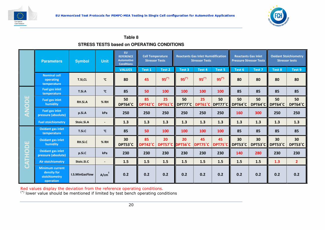
Table 8 presents the overall set of Stressor Tests based on Operating Conditions.
EU Harmonized Test Protocols for PEMFC-MEA Testing in Single Cell configuration for Automotive Applications
20
Table 8
STRESS TESTS based on OPERATING CONDITIONS
Parameters Symbol Unit
EU
REFERENCE
Automotive
Conditions
Cell Temperature
Stressor Tests Reactants Gas Inlet Humidification
Stressor Tests Reactants Gas Inlet
Pressure Stressor Tests Oxidant Stoichiometry
Stressor tests
VALUES Test 1 Test 2 Test 3 Test 4 Test 5 Test 6 Test 7 Test 8 Test 9
Nominal cell
operating
temperature T.Si,CL °C 80 45 95
(*) 95
(*) 95
(*) 95
(*) 80 80 80 80
AN
OD
E
Fuel gas inlet
temperature T.Si.A °C 85 50 100 100 100 100 85 85 85 85
Red values display the deviation from the reference operating conditions. (*) lower value should be mentioned if limited by test bench operating conditions
EU Harmonised Test Protocols for PEMFC-MEA Testing in Single Cell Configuration for Automotive Applications
21
4 PERFORMANCE CHARACTERIZATION METHOD
It is proposed that each test should start with an appropriate Leak test; Cell break-in; and Cell Conditioning.
The methodology of these tests is suggested in Appendixes D.1; D.2 and D.3:
MEA assembled in single cell test hardware should be tested at automotive reference
conditions at the Beginning of Test (BoT) before assessing cell performance at each stressor condition by means of polarization curve measurements in galvanostatic mode (constant current density) as presented in Appendix E.
At the End of Test (EoT) the last polarization curve measurements shall be performed under the reference conditions to evaluate the degradation occurred during execution of the tests under stressor conditions.
4.1 PERFORMANCE CRITERIA
Agreed Performance Criteria
• cell voltage at 0.1 A/cm2: representative for activation polarization
losses – kinetic regime;
• cell voltage at 0.8 A/cm2 : representative for ohmic resistance losses –
linear regime;
• cell voltage at 1.8 A/cm2 (≥ 0.4V): representative for concentration
polarization – mass transfer limitations regime. If the cell current density does not reach 1.8 A/cm2 at a voltage ≥0.4 V then the corresponding current density at this voltage should be reported.
The cell performance measured at each stressor condition is assessed by recording the cell voltage at 0.1, 0.8 A/ cm2 and 1.8 A/cm2. These measured test outputs are then normalized according to equation 4.1.
normalized test output 1
(Equation 4.1)
The normalized test results are presented in a spider plot where each normalized test result is represented on the appropriate stressor axis. An example of such a spider plot is given in Fig. 3.
EU Harmonised Test Protocols for PEMFC-MEA Testing in Single Cell Configuration for Automotive Applications
22
Figure 3:
Example of a spider plot showing normalised cell voltages (normalised test
outputs) for 9 tests conducted under different stressor conditions with respect
to the test conducted at reference conditions
On each axis of the spider plot, the normalized reference test results (equation 4.1) are zero by definition. The results obtained from each stressor test compared with the reference tests provide an indication of cell performance variation from the reference one at the different stressing conditions.
4.2 MEA SPECIFICATIONS
It is suggested that a minimum set of information on MEA specifications should be provided according to the table presented in Appendix G.
-0.15
-0.1
-0.05
0
0.05
0.1
0.15
Test 1
Test 2
Test 3
Test 4
Test 5Test 6
Test 7
Test 8
Test 9
Normalized test output Reference condition
EU Harmonised Test Protocols for PEMFC-MEA Testing in Single Cell Configuration for Automotive Applications
23
5 LOAD CYCLES
The purpose of load cycles is to make a laboratory simulation of real driving conditions. In this view the load cycle is used to assess fuel cell durability during a relatively long period by exposing the cell to the same load cycle repetitively.
Automotive PEMFC power units are subjected to different operation regimes including fast variations in load, prolonged OCV exposure as well as periods of steady state operation during their useful life.
When such a cycle is repetitively applied to the cell under test for 500 hours it corresponds to a vehicle utilization average of 80 minutes daily over one year (yearly mileage of approximately 16,000 km).
The Fuel Cell Cycle is based on the “New European Driving Cycle” (NEDC) depicted in Figure 4. The NEDC cycle is used for type approval of light-duty vehicles and features periods of acceleration, deceleration and constant speed. It consists of four repetitions of a low speed urban cycle of 195 seconds each followed up by a part which simulates a motorway (highway) driving cycle of 400 seconds duration. That is equivalent to a theoretical distance of approximately 11 km driven in about 20 min.
Figure 4:
NEDC profile according to EU Directive 98/69/CE
EU Harmonised Test Protocols for PEMFC-MEA Testing in Single Cell Configuration for Automotive Applications
24
The speed profile of NEDC (Figure 4) was applied to a typical fuel cell car and the resultant measured fuel cell load current profile is shown in Figure 5.
Figure 5:
Current profile for a PEM single fuel cell
The load current cycle presented in Figure 5 cannot be easily reproduced on the fuel cell test benches so it was necessary to simplify the cycle into a FC modified cycle which can be performed by different test benches currently used by the majority or research organisations.
The transformation approach that was used is by “squaring the cycle”, by ensuring that the following equation 5.1, which represents the total electrical charge delivered by the fuel cell during the entire duration of the NEDC cycle is satisfied in both cases. At the initial stage as in Fig. 5 and in the transformed one as in Fig 6.
_ ∙ _ !"#$ ∙ %%&'
'
%%&'
' Equation 5.1,
Where I is the cell current.
The result of the transformation is presented in the Figure 6.
EU Harmonised Test Protocols for PEMFC-MEA Testing in Single Cell Configuration for Automotive Applications
25
Figure 6:
Profile of ratio of current density to maximum current density expressed as
percentage vs cycle duration adapted for testing PEMFC single cells to resemble
the NEDC cycle (vehicle speed vs. cycle duration) as a load (current) profile
However, the current cycle as described in Figure 6 would produce several periods of prolonged exposure to OCV conditions thereby causing excessive degradation.
To minimize OCV exposure, all but the initial period of 15 seconds and the last period of 21 seconds of OCV are replaced by a current density corresponding to 5% of maximum load (current), see Appendix F. The thus modified cycle called thereafter the Fuel Cell Dynamic Load Cycle, FC-DLC (Figure 7) and it was derived in collaboration with the FCH-JU supported FCH-JU 303445 StackTest project.
EU Harmonised Test Protocols for PEMFC-MEA Testing in Single Cell Configuration for Automotive Applications
26
Figure 7:
Fuel Cell Dynamic Load Cycle
More details corresponding to the method for calculating the maximum current load and the different periods of the various steps of the cycle are given in Appendix [D].
EU Harmonised Test Protocols for PEMFC-MEA Testing in Single Cell Configuration for Automotive Applications
27
6 ENDURANCE TESTING
The successful operation of a fuel cell depends not only on its performance but also on its durability. Durability is the capability of the fuel cell to maintain its performance over a period of time, without significant irreversible changes to the initial recorded performance being detrimental.
Fuel cell durability is evaluated through ENDURANCE testing by applying a load profile to the cell and measuring performance degradation in terms of cell voltage as function of operating hours. Performance degradation over time cannot be avoided but the rate should be minimized and assessed.
Fuel cell voltage measurements are typically performed by polarisation curves at BoT and EoT and could also be performed periodically during various stages of the endurance test for establishing the evolution of cell voltage at a given current (degradation rate) and to understanding the specific effects of degradation (e.g. change in mass transport properties).
To assess the cell degradation rate two main load profiles are proposed for endurance testing:
• Dynamic current load cycle
• On / off current load cycle
A profile of steady state current load is not addressed in this activity as it is not considered as relevant for automotive applications.
6.1 DYNAMIC LOAD CYCLING ENDURANCE TEST
The test comprises a total of 1400 cycles which correspond to one year of usual vehicle use equivalent to approximately 15,400 km of driving. It is assumed that the vehicle is consuming the entire hydrogen fuel contained in a typical automotive tank which provides an average range of approximately 550 km.
Each Endurance test starts with the appropriate cell leak test, break-in and conditioning (see Appendix E), and is performed according to the following protocol (composed of 5 steps).
1. Set the test operating conditions at reference or stressor conditions, Table 8.
2. At the Beginning of Test (BoT), perform a polarization curve according to Appendix E or record the cell voltage at 0.1, 0.8 and 1.8 A/cm2 with dwell times as specified in Appendix E.
EU Harmonised Test Protocols for PEMFC-MEA Testing in Single Cell Configuration for Automotive Applications
28
3. Operate the cell at the FC-DLC driving cycle (Figure 7) for 50 consecutive cycles (50 cycles = one test block).
4. At the end of 50 FC-DLC perform a polarization curve or record the cell voltage at 0.1; 0.8 and 1.8 A/cm2 and compare with measurements performed at BoT and observe the degradation rate in µV/hour.
5. Repeat steps from 3 to 4 up to a total of 1400 driving cycles.
6.2 REVERSIBLE and IRREVERSIBLE DEGRADATION
As reported in literature, part of the overall voltage loss observed during cell operation, under steady state or load cycling, may be recovered upon cell shutdown and consecutive restart. It has also been reported that such an operation may lead to reduced overall degradation rate, as compared to uninterrupted (steady or dynamic) operation. This suggests that the overall voltage degradation of the cell is composed of reversible and irreversible contributions.
The recoverable part of the overall voltage loss is called reversible voltage loss ∆Vrev. For a generic test block in which the fuel cell is operated (steady or dynamic operation) for a time ∆ti between a start-up and a shut-down, the reversible voltage loss ∆Vrev,i can be calculated as the difference between the cell voltage V(ti+1) at the starting time ti+1 of the test block i+1 and the voltage V(ti+ ∆ti) at the ending time ti + ∆ti of the test block i as follows:
∆Vrev,i = V(ti+1) – V(ti+ ∆ti). Equation 6.1
The irreversible (non-recoverable) part of the voltage loss due to a test block i can be defined as the difference between the cell voltage V(ti) at starting time ti of the test block i and the voltage V(ti+1) at the ending time ti+1 of the recovery period ∆tri (i.e. the voltage at starting time ti+1 of test block i+1) as follows:
∆Virrev,i = V(ti) – V(ti+1). Equation 6.2
A graphical description of reversible and irreversible contributions is given in Figures 8 and 9.
EU Harmonized Test Protocols for PEMFC-MEA Testing in Single Cell configuration for Automotive Applications
29
Figure 8: Reversible & irreversible degradation
test block i-1 test block i test block i+1
EU Harmonized Test Protocols for PEMFC-MEA Testing in Single Cell configuration for Automotive Applications
EU Harmonised Test Protocols for PEMFC-MEA Testing in Single Cell Configuration for Automotive Applications
31
The total irreversible voltage loss ∆Virrev,1→N at EoT upon performing N test blocks in
total expressed in () is the sum of all irreversible voltage losses as follows:
∆Virrev, 1→N = ∑ ∆),,./% )0%1 )0.1 Equation 6.3
The total irreversible voltage loss (degradation) rate )2,,%→. of all N test blocks
can be expressed in () per hour. It is the ratio of ∆Virrev,1→N to the sum of the duration of all N test blocks as follows:
)2,,%→. 4)5##$6,1→
∑ ∆51 5
Equation 6.4
Therefore to distinguish between reversible and irreversible degradation phenomena the following protocol is proposed:
1. Set the test operating conditions: reference or stressor conditions.
2. At the Beginning of the Test (BoT), perform a polarization curve or record cell
voltage at 0.1, 0.8 and 1.8 A/cm2, representative of V(t1).
3. Operate the cell under the FC-DLC driving cycle for 50 consecutive cycles.
4. Perform a polarization curve or record the cell voltage at 0.1; 0.8 and 1.8 A/cm2,
representative of V(t1 + ∆t1) (or V(ti + ∆ti) in later iterations)
5. Perform a recovery protocol (an example is given in chapter 6.3).
6. After N2 purge of the anode side for few minutes, restart the cell setting the initial operating conditions and let the cell stabilise for 30 min.
7. Perform a polarization curve or record the cell voltage at 0.1; 0.8 and 1.8 A/cm2, representative of Vi.
8. Repeat steps from 3 to step 7. The test ends with step 4 after 1,400 FC-DLC driving cycles, or when EOL conditions are reached.
9. Cool the cell down. End of Test (EoT).
Comparison between the two polarization curves (or cell voltages recorded) at step 4 and step 7 (and between subsequent iterations of step 7), will allow the calculation of the reversible and irreversible voltage degradation according to Equation 6.1, - 6.4.
EU Harmonised Test Protocols for PEMFC-MEA Testing in Single Cell Configuration for Automotive Applications
32
6.3 PERFORMANCE RECOVERY PROTOCOL
1. Disconnect the load. 2. Stop air flow to the cathode. 3. Shut off cathode exit. 4. Maintain minimum fuel flow at anode until cell voltage vanishes plus 10 minutes 5. Close fuel supply 6. Flush both anode and cathode compartments with Nitrogen for safety reasons 7. Flush anode and cathode with air 8. Let the cell to cool down to ambient temperature 9. Keep the cell under ambient conditions for about 16.5 hours being equivalent to
the total duration of 50 consecutive FC-DLC, see Figure 10. 10. Flush both anode and cathode compartments with Nitrogen for safety reasons 11. Restart setting test operating conditions
Figure 10:
Schematic of a typical sequence of FC-DLC application with 50 performed cycles
and intermittent polarisation curve measurements including a cell recovery
phase for PEMFC single cell endurance testing
Recovery phase
EU Harmonised Test Protocols for PEMFC-MEA Testing in Single Cell Configuration for Automotive Applications
33
6.4 ON-OFF CYCLING ENDURANCE TEST
The aim of ON-OFF Cycling Endurance Test is to stress the fuel cell by means of instantaneous and alternating phases of on and off loads causing frequent changes in pressure and temperature which are more abrupt for pressure changes rather than temperature changes. The cell is tested by applying loads at 1.5A/cm2 or at the maximum current density that the MEA could reach (ON phase) followed by a period of carefully shutdown (OFF phase) where the load (current) is set to zero. The cell voltage is recorded during the ON phase to observe its evolution. At BoT and EoT, polarisation curve measurements are performed.
The ON-OFF Cycling Endurance test starts with the appropriate cell leak test, break-in and conditioning (cf. APPENDIX E) and is performed according to the following protocol:
1. Set the test operating conditions: reference or stressor conditions.
2. At (BoT), perform a polarization curve measurement or record cell voltage at 0.1; 0.8 and 1.8 A/cm2. Record also the average current density at 0.65 V (as average of ascending and descending polarisation curve measurements). This value of current is used as 100% current density (Figure 11 below) of the ON/OFF profile.
3. Increase the current density to 100%.
4. Operate the cell at the specified operating conditions for 30 minutes and record the cell voltage while averaging the last 60 seconds of recording.
5. Decrease the current load to zero current and disconnect the load.
6. Stop reactant supply at the cell inlet (no purge); thereby their inlet pressures are reduced. Let the cell cool down to ambient temperature where it is kept for 30 minutes.
7. Restart the cell by setting the initial T, P, RH operating conditions and then setting up the current and have the cell voltage stabilised.
8. Repeat steps from step 3 to 6 until the cell voltage, recorded at step 4 has decreased by 10% of its initial value.
9. At (EoT), perform measurements as in step 2.
10. Cool the cell down. End of Test
The following figure 11 shows a typical On/Off cycle sequence
EU Harmonised Test Protocols for PEMFC-MEA Testing in Single Cell Configuration for Automotive Applications
34
Figure 11:
Schematic of a typical sequence of ON /OFF Cycling ENDURANCE testing for
PEMFC single cell (cooling and heating time are not represented)
0
0.2
0.4
0.6
0.8
1
1.2
1.4
1.6
1.8
0 30 60 90 120 150 180 210 240
Cu
rre
nt
de
nsi
ty (
A/c
m2)
Test cycle duration (min)
0
20
0 30 60 90 120 150 180 210 240
Ra
tio
of
curr
en
t d
en
sity
, %
Test cycle duration (min)
EU Harmonised Test Protocols for PEMFC-MEA Testing in Single Cell Configuration for Automotive Applications
35
7 CONTROL ACCURACY & INSTRUMENT UNCERTAINTY
Control accuracy and instrument uncertainty are bounded by test-bench specifications/limitations. For each test, test inputs and outputs are defined. Test input is a physical quantity which defines the testing conditions while Test output is a physical quantity resulting from carrying out the tests.
Figure 12 provides an overview of all test inputs and test outputs involved during a typical polarisation curve test. As variations of test inputs have an impact on the measured outputs it is very important to accurately control all test inputs.
Figure 12:
Fuel cell test input/output schematic
EU Harmonised Test Protocols for PEMFC-MEA Testing in Single Cell Configuration for Automotive Applications
36
7.1 MEASURED PARAMETERS
The following minimum set of parameters should be measured and recorded for data analysis and reporting:
Test input / output Parameter Location of sensor
1. Cell current (or current density) Load module
2. Cell voltage Cell Hardware HW, Current collectors, Voltage terminals
3. Temperatures
• Cell Temperature Cathode plate, possibly in the center • Oxidant inlet as close as possible to cell HW inlet • Oxidant outlet as close as possible to cell HW outlet • Oxidant inlet RH (or Dew point) as close as possible to cell HW inlet • Fuel inlet as close as possible to cell HW inlet • Fuel outlet as close as possible to cell HW outlet • Fuel inlet RH (or Dew point) as close as possible to cell HW inlet • Coolant inlet (if used) as close as possible to cell HW inlet • Coolant outlet (if used) as close as possible to cell HW outlet
4. Pressures
• Oxidant inlet as close as possible to cell HW inlet • Oxidant outlet as close as possible to cell HW outlet • Fuel inlet as close as possible to cell HW inlet • Fuel outlet as close as possible to cell HW outlet
The measuring parameters listed above should be recorded and stored with a frequency high enough to ensure that all relevant changes in the parameters are recorded for later data analyses. The sampling frequency is recommended to be 1.0 Hz or higher.
EU Harmonised Test Protocols for PEMFC-MEA Testing in Single Cell Configuration for Automotive Applications
37
- Table 9:
Test bench instrumentation and measurement uncertainty
CE
LL
Test input Symbol Unit Instrument
Uncertainty1
Measurement
uncertainty2
Sampling rate
Values Values Values
Nominal cell operating temperature
T.Si,CL l °C ± 1K ± 2 K ≥≥≥≥1 Hz
Cell voltage U.S.CL V ± 0.5%4 ± 0.5%
4 ≥≥≥≥1 Hz
Current I.S A
± 1%4 0.001A ≥≥≥≥1 Hz
AN
OD
E Fuel gas inlet temperature T.Si.A °C ± 1 K ± 2 K ≥≥≥≥1 Hz
Fuel gas inlet humidity RH.Si.A
% RH ± 2 K
3 ± 5%FS ≥≥≥≥1 Hz
Fuel gas inlet pressure (absolute)
p.Si.A kPa ± 3%4 ± 2% ≥≥≥≥1 Hz
Fuel flow rate F.Si.A - ± 2%4 ± 2%FS ≥≥≥≥1 Hz
CA
TH
OD
E Oxidant gas inlet
temperature
T.Si.C °C ± 1K ± 2K ≥≥≥≥1 Hz
Oxidant gas inlet humidity RH.Si.C
% RH ± 2K3 ± 5%FS ≥≥≥≥1 Hz
Oxidant gas inlet pressure (absolute)
p.Si.C kPa ± 3%
4 ± 2% ≥≥≥≥1 Hz
Oxidant flow rate F.Si.C - ± 2%4 ± 2%FS ≥≥≥≥1 Hz
1- According to IEC62282-7-1
2- According to FCTesQA 3- ±2K of Dew Point Temperature (DPT) 4- percentage of maximum expected value (IEC62282-7-1)
EU Harmonised Test Protocols for PEMFC-MEA Testing in Single Cell Configuration for Automotive Applications
38
BIBLIOGRAPHY
[1] FUEL CELLS AND HYDROGEN JOINT UNDERTAKING (FCH JU); Multi - Annual Implementation Plan 2008 – 2013. Available at the following internet address:
[3] Membrane and Catalyst Performance targets for Automotive Fuel Cells by FCCJ Membrane, Catalyst, MEA WG; A Ohma, K Shinohara, A Iiyama, T Yoshida, A Daimaru, ECS Transactions, 41 (1) 775 784 (2011).
[4] Procedure for Performing PEM Single Cell testing, DOE April 2009. Available at following internet address: http://www1.eere.energy.gov/hydrogenandfuelcells/pdfs/htmwg_may09_pem_single_cell_testing.pdf
[5] FCTesQA/FCTESTNET SC 5.2 testing module, "Polarisation curve for a PEFC single cell". Available at the following internet address:
[6] FCTesQA/FCTESTNET SC 5.1 testing module "Testing the humidification sensitivity of a single PEFC. Characterisation of the performances of a PEFC operating with fuel and oxidant at various relative humidity. Available at the following internet address:
[7] FCTesQa/FCTESTNET SC 5.6 testing module "Testing the voltage and the power as a function of time at a fixed current density Long term durability steady test for a single PEFC. Available at the following internet address:
[8] IEC 62282-7-1 Single Cell Test Methods for Polymer Electrolyte Fuel Cell (PEFC)
[9] A. Kabza et al. TM P-00 Stack-Test Master Document - Project reference: FCH JU 303445
[10] Q. Yan, H. Toghiani, H. Causey, Steady state and dynamic performance of proton exchange membrane fuel cells (PEMFCs) under various operating conditions and load changes, J. Power Sources. 161 (2006) 492–502. doi:10.1016/j.jpowsour.2006.03.077.
EU Harmonised Test Protocols for PEMFC-MEA Testing in Single Cell Configuration for Automotive Applications
39
modelling of PEM fuel cells: An investigation into the effects of water flooding, Chemical Engineering Science. 64 (2009) 2781–2794. doi:10.1016/j.ces.2009.01.060.
[12] J. Zhang, Y. Tang, C. Song, Z. Xia, H. Li, H. Wang, et al., PEM fuel cell relative humidity (RH) and its effect on performance at high temperatures, Electrochimica Acta 53 (2008) 5315–5321. doi:10.1016/j.electacta.2008.02.074.
[13] D.H. Jeon, K.N. Kim, S.M. Baek, J.H. Nam, The effect of relative humidity of the cathode on the performance and the uniformity of PEM fuel cells, Int. J. Hydrogen Energy. 36 (2011) 12499–12511. doi:10.1016/j.ijhydene.2011.06.136.
[14] P. W. Majsztrik, Mechanical and transport properties of Nafion® for PEM fuel cells; temperature and hydratation effects, Dissertation, Princeton University , Jan 2008
[15] S S. Kocha, J. D Yang, J S. Yi, Characterization of Gas Crossover and Its Implications in PEM Fuel Cells, AIChE Journal 2006 Vol. 52, No. 5, 1916-1925
[16] Chris K. Dyer, Patrick T. Moseley,Zempachi Ogumi, David A. J. Rand, Bruno Scrosati, Encyclopedia of Electrochemical Power Sources (2013) 299-305. Isbn:978-0-444-52093-7
[17] Strategic Energy Technology (SET) Plan, Towards an integrated roadmap: Research & Innovation challenges and needs of the EU energy system.Available at the following internet address:
[18] Fuel Cell Testing Protocols: An International Perspective; I. Bloom,J.K. Basco, L.K. Walker, T. Malkow, G. DeMarco, A. Saturnio, G. Tsotridis. ISBN 978-92-79-29460-0
Available at the following internet address:
http://www.osti.gov/bridge
[19] I. Bloom, L. Walker, J. Basco, T. Malkow, G. De Marco, G. Tsotridis, A comparison of Fuel Cell Testing protocols e A case study: Protocols used by the U.S Department of Energy, European Union, International Electrotechnical Commission /Fuel Cell Testing and Standardization Network, and Fuel Cell Technical Team, Journal of Power Sources 243 451-457, 2013
[20] I. Bloom, L. Walker, J. Basco, T. Malkow, G. De Marco, G. Tsotridis, A Comparison
of Fuel Cell Test Protocols, ECS Transactions. 30 (1) 227, 2011. [21] R. Bove, T. Malkow, A. Saturnio, and G. Tsotridis, PEM fuel cell stack testing in
the framework of an EU-harmonized fuel cell testing protocol: Results for an 11 kW stack, Journal of Power Sources 180 (1) 452–460, 2008.
[22] T. Malkow, A. Saturnio, A. Pilenga, G. De Marco, M. Honselaar, and G. Tsotridis,
Assessment of PEFC performance by applying harmonized testing procedure, International Journal of Energy Research 35 (12) 1075–1089, 2011.
EU Harmonised Test Protocols for PEMFC-MEA Testing in Single Cell Configuration for Automotive Applications
Conc.Si.C.GasX Concentration Cell inlet cathode gas X
CV Cyclic Voltammetry
DPT Dew Point Temperature
DPT.Si.A Dew Point Temperature Cell inlet Anode
DPT.Si.C Dew Point Temperature Cell inlet Cathode
EoT End of Test
FCH-JU Fuel Cell and Hydrogen Joint Undertaking
F.Si.A Flow rate Cell input Anode
F.Si.C Flow rate Cell input Cathode
HW Hardware
HFR High Frequency Resistance
IEC International Electrotechnical Commission
MEA Membrane Electrode Assembly or Assemblies
NEDC New European Drive Cycle
OCV Open circuit voltage
PEFC Polymer Electrolyte or Pproton Exchange Membrane Fuel Cell
p.Si.A Pressure Cell inlet Anode
p.Si.C Pressure Cell Inlet Cathode
p.PC.A Pressure Cell outlet Anode
p.PC.C Pressure Cell outlet Cathode
RH Relative Humidity
RH.Si.A Relative Humidity Cell inlet Anode
RH.Si.C Relative Humidity Cell inlet Cathode
Std Standard deviation
Sterr Standard error
Stoic.Si.A Stoichioetry Cell inlet Anode
Stoic.Si.C Stoichioetry Cell inlet Cathode
T.Si.A Temperatore Cell inlet Anode
EU Harmonised Test Protocols for PEMFC-MEA Testing in Single Cell Configuration for Automotive Applications
41
T.Si.C Temperature Cell inlet Cathode
T.Si.CL Cell Temperature
U.S.CL Cell Voltage
EU Harmonised Test Protocols for PEMFC-MEA Testing in Single Cell Configuration for Automotive Applications
42
APPENDIX A: RELATIONSHIP OF RELATIVE HUMIDITY AND
DEW POINT
The relative humidity of a gas at a given pressure and temperature is defined as the ratio of actual vapour pressure and the vapour pressure of water when the gas is saturated:
RH = pvap / pvap sat ·100% (Equation A.1)
pvap sat can be calculated from the Antoine’s empirical equation; where A, B and C are constants for the specified temperature range [Perry's Chemical Engineer' Handbook, McGraw Hill]:
Log (pvap sat) = A - B / (T + C) (Equation A.2)
Range, T (ºC) A B C
H2O 1 -100 10.196213 1732.7549 233.426
Where T is the gas temperature expressed in ºC and Pressure is expressed in Pa.
pvap is calculated following the same formula, where Tdew is the dew point temperature:
Log (pvap) = A - B / (Tdew + C) (Equation A.3)
When the dew point of fuel / oxidant gas at inlet is equal to the cell temperature, the reactant RH is 100 %.
Using these equations, RH can be calculated as a function of the dew point temperature for a particular cell temperature (Cf. Figure A.1).
It is also possible that the test bench software contains already an algorithm to calculate the water flow or to set the dew point if the RH is given as set up condition.
Test bench suppliers should then provide information which algorithm was used.
EU Harmonised Test Protocols for PEMFC-MEA Testing in Single Cell Configuration for Automotive Applications
43
Figure A.1
Relative humidity versus dew point for different cell temperatures at 45, 80 and 95°C
EU Harmonised Test Protocols for PEMFC-MEA Testing in Single Cell Configuration for Automotive Applications
44
APPENDIX B: PEMFC MATERIAL & COMPONENT FAILURE MODES & CAUSES
The following Table summarizes the most relevant material and component failure modes of PEMFC
Table B.1
Component Failure Modes Causes
Membrane
Mechanical degradation
Mechanical stress due to heterogeneous pressing , heterogeneous swelling Puncture due to fibres
corrosion of electrocatalyst support / dissolution of Pt
Flooding
Dissolution of alloying elements / contamination
Change in hydrophobicity of materials
GDL
Decrease in mass transport
Decrease in water management ability
Thinning
Mechanical stress; compression
Change in the hydrophobicity of materials
Corrosion
Bipolar plate
Conductivity loss
Fracture/deformation
Corrosion; oxidation
Mechanical stress
Change in wetting behaviour
Sealing
gasket
Mechanical failure; brittleness Deformation, compression, chemical reaction
EU Harmonised Test Protocols for PEMFC-MEA Testing in Single Cell Configuration for Automotive Applications
45
APPENDIX C: STRESSORS
The following table summarizes the most relevant stressors for PEMFC which could have a positive or negative impact on cell performance.
Table C.1
Stressors and their likely effects impacting on cell performance
Stressor Stressor
positive effect
Stressor
negative effect
Cell temperature
- Activation losses reduction:
• The exchange current density increases with the increase of cell temperature,
• mass transport enhancement with the increase of cell temperature, due to increase of diffusivity,
• Increase of conductivity of the membrane with temperature increase.
- Water management control:
• Increased temperature increases the capacity of the gases leaving the fuel cell to carry away water.
- Nafion membrane lifetime decreases at high temperature
- Corrosion of electrodes increases with temperature increase (faster growth of Pt-particles and Pt-particles dissolution, enhanced carbon corrosion).
- Water management control:
• As water production rate increases proportionally with the current this poses a risk of flooding if the cell temperature is lower than the "water saturation" temperature at given current density for each temperature and stoichiometry value.
Ambient
Temperature Sub-
Zero conditions
--- - Activation losses increase due to:
• reduction of membrane conductivity,
• water freezing and channel clogging
EU Harmonised Test Protocols for PEMFC-MEA Testing in Single Cell Configuration for Automotive Applications
46
Stressor Stressor
positive effect
Stressor
negative effect
- Delamination of MEA, backing layers and GDL, increased porosity of catalyst layer, with mechanical degradation and electrical interfacial contact reduction
Fuel inlet
temperature
- Water management control:
• Contribute to avoid water condensation, flooding issues with temperature ranges from DPT+5°C to DPT+10°C.
Excessive difference between cell and fuel inlet temperature could generate a non-homogeneous temperature distribution inside the cell, i.e. water management at the inlet could be affected thus creating dry or flooded zones.
The severity of the effect is reduced as long as the dew point is lower than the inlet temperature
• Increase of conductivity of the membrane with humidity increase due to higher water content in the membrane.
• Low values of humidity may lead to accelerated MEA degradation.
• Risk of flooding at high humidity.
• In the lower current density region, the lower the degree of humidification, the lower the fuel cell performance. Lower severity effect at high current density.
Fuel inlet
stoichiometry
- Activation losses reduction:
• Additional reactant feed above the amount required by the electrochemical reaction has a beneficial effect replacing unreacted fuel up to a certain ratio.
• Low stoichiometry values can produce Fuel starvation that may lead to anode catalyst degradation due to carbon corrosion (reaction with H2O with production of O2 and H+)
• With low flow, local starvation can be due to water droplets getting stuck in the flow channels
Fuel outlet
pressure
-Activation losses reduction:
• Increase of exchange current density of the
Might produce mechanical stress on the membrane
EU Harmonised Test Protocols for PEMFC-MEA Testing in Single Cell Configuration for Automotive Applications
47
Stressor Stressor
positive effect
Stressor
negative effect
membrane with pressure increase due to:
A. higher water content in the membrane.
B. reactant partial pressure increase.
Oxidant inlet
temperature
- Water management control:
• Contribute to void water condensation, flooding issues with temperature ranges from DPT+5°C to DPT+10°C.
Excessive difference between cell and Oxidant inlet temperature could generate a non-homogeneous temperature distribution inside the cell, i.e. water management at the inlet could be affected thus creating dry or flooded zones.
Low severity as long as the dew point is lower than the inlet temperature
Oxidant inlet
humidity
- Activation losses reduction:
• increase of conductivity of the membrane with humidity increase due to higher water content in the membrane
• Low values of humidity may lead to accelerated MEA degradation.
• Risk of flooding at high humidity.
Oxidant inlet
stoichiometry
- Activation losses reduction:
• Additional reactant feed above the amount required by the electrochemical reaction has a beneficial effect replacing unreacted oxidant up to a certain ratio.
• Low stoichiometry values can produce Oxidant starvation. With low flow local starvation can be due to water droplets getting stuck in the flow channels
Oxidant outlet
pressure
-Activation losses reduction:
• Increase of exchange current density of the membrane with pressure increase due to:
A. higher water content in the membrane.
B. reactant partial pressure increase.
May produce mechanical stress on the membrane
EU Harmonised Test Protocols for PEMFC-MEA Testing in Single Cell Configuration for Automotive Applications
48
Stressor Stressor
positive effect
Stressor
negative effect
Fuel-to-oxidant
pressure
difference
• May influence diffusive water transport and therefore water management, particularly at the anode.
• May produce mechanical stress on the membrane
Load factor
(=multiplier for all
load current
values of the load
cycle performed
between
Beginning of Test
and End of Test)
Load factors < 1 may lead to lower cell degradation rate.
Load factors > 1 may lead to accelerated cell degradation rate.
Applied
mechanical load
(pressure or
torque) to tighten
cell prior to
testing
• Decrease in overall cell contact resistance due to better contact between current collector / bipolar plate and MEA.
• Might produce mechanical stress on the membrane
• Reduced water removal capacity for GDL due to its deformation and protrusion into gas channels.
• Increased pressure drop due to GDL intrusion
EU Harmonised Test Protocols for PEMFC-MEA Testing in Single Cell Configuration for Automotive Applications
49
APPENDIX D: TESTING PROCEDURES
Each test should start with an appropriate Leak test, Cell break-in, and Cell Conditioning following the procedure described below or using equivalent ones as per supplier recommendation or following IEC 62282-7-1:
D.1 LEAK TEST
Objectives:
• Measure leakage rate by pressure decrease in anode and cathode compartment; • Assure gas tightness of cell and test station.
Procedure:
1. Start dry nitrogen flow in anodic and cathode compartment at minimum flow rate;
2. Pressurize the anode compartment to 320 kPa (abs) and the cathode compartment to 300 kPa (abs). The pressure difference between anode and cathode (20kPa) should be the same as for the reference operating conditions;
3. Reduce nitrogen flow to zero;
4. Keep cell at this state for minimum 10 minutes;
5. Measure pressure decrease in both compartments for minimum 10 minutes;
Data analysis:
Plot anode and cathode pressure versus test duration for both situations when no cell is used and when the cell is used to determine the influence of the test bench gas tightness.
Acceptance criterion: the test is passed if the leak rate is lower than 0.3 kPa/min.
EU Harmonised Test Protocols for PEMFC-MEA Testing in Single Cell Configuration for Automotive Applications
50
D.2 CELL BREAK-IN
The following suggestion should be used if specific instructions are not provided by the MEA manufacturer:
• Increase the cell temperature to 80°C, reactants inlets temperature to 85°C, RH to 100% (with respect to the cell temperature) and back pressure to 150 kPa (abs) on Anode and 130 kPa (abs) on Cathode, while avoiding the gas inlet dew points to exceed reactants inlets and cell temperatures.
• Increase the current density in steps of 100 mA/cm2 up to 800 mA/cm2 while keeping the cell voltage > 400 mV, and let the cell stabilize for 6 hours.
• Set the reactants RH to 50% and increase the current while keeping the cell voltage > 400 mV up to 1 A/cm2. Hold the cell in these conditions for at least 2 hours.
• Stability validation by 0.4 V to 0.8 V cycles with stoichiometric condition.
• At the 1.0 A/cm2 set point perform the reference 1 recording for 5 min, move to a high potential (0.8 V) and hold for 5 min. Subsequently move to a low potential (0.4 V) and hold for 5 min also. Repeat these jumps till three high voltage and two low voltage plateau measurements have been performed (Figure D.1) and hold for 0.5 h at the 1.0 A/cm2 set point to record the reference 2 for 5 min.
Figure D.1:
Cell Break-in protocol
EU Harmonised Test Protocols for PEMFC-MEA Testing in Single Cell Configuration for Automotive Applications
51
The recommended stability criterion is based on the cell voltage fluctuation and it is considered fulfilled when it is lower than ±5 mV in the reference 2 step. Additionally, the cell voltage fluctuation between the reference time frame 1 and 2 should be lower than ±10 mV. For higher fluctuation the whole or parts of the procedure have to be repeated till the targets are reached.
D.3 CELL CONDITIONING
The aim of the conditioning procedure is to assure that the cell voltage will be stable before the test initiation. A stability criterion is defined based on the difference between the cell voltages measured for a specified period. It is recommended that the variations in the cell voltage are lower than +/- 5 mV during the last hour before ending the conditioning step.
Cell conditioning starts by setting the required operating conditions and maintain these conditions until the cell voltage is stable that is when it varies by not more than +/-5 mV during the last hour of conditioning procedure.
In case no cell stability is obtained within 6 hours of operation a repetition of the break-in and conditioning could be reconsidered.
If again the cell stability is not met troubleshooting actions shall take place.
EU Harmonised Test Protocols for PEMFC-MEA Testing in Single Cell Configuration for Automotive Applications
52
APPENDIX E: POLARISATION CURVE TESTING PROCEDURE
The objective of performing polarisation curve measurements is to determine the MEA performance in terms of cell voltage and power density against current density at specified operating conditions. The dwell time of each set point should be sufficient long enough to ensure that stabilisation criteria of cell voltage of ±5 mV within 2 min but not longer than 15 min, except for the OCV which shall not exceed 1 min dwell time. The proposed set points are summarised in Table E.1 and Figure E.1[4,5,8].
Table E.1:
Polarisation curve set-points
Set point no.
Current density A/cm²
Recommended dwell time (s)
Recommended Data acquisition
time (s)
1 0.00 ≤60 ≥30
2 0.02 ≤60 ≥30
3 0.04 ≤60 ≥30
4 0.06 ≤60 ≥30
5 0.08 ≤60 ≥30
6 0.10 ≤60 ≥30
7 0.20 ≥120 ≥30
8 0.30 ≥120 ≥30
9 0.40 ≥120 ≥30
10 0.60 ≥120 ≥30
11 0.80 ≥120 ≥30
12 1.00 ≥120 ≥30
13 1.20 ≥120 ≥30
14 1.40 ≥120 ≥30
15 1.60 ≥120 ≥30
16 1.80 ≥120 ≥30
17 2.00 ≥120 ≥30
18 1.80 ≥120 ≥30
19 1.60 ≥120 ≥30
20 1.40 ≥120 ≥30
21 1.20 ≥120 ≥30
22 1.00 ≥120 ≥30
23 0.80 ≥120 ≥30
24 0.60 ≥120 ≥30
25 0.40 ≥120 ≥30
26 0.30 ≥120 ≥30
27 0.20 ≥120 ≥30
28 0.10 ≤60 ≥30
29 0.08 ≤60 ≥30
30 0.06 ≤60 ≥30
EU Harmonised Test Protocols for PEMFC-MEA Testing in Single Cell Configuration for Automotive Applications
53
Set point no.
Current density A/cm²
Recommended dwell time (s)
Recommended Data acquisition
time (s)
31 0.04 ≤60 ≥30
32 0.02 ≤60 ≥30
33 0.00 ≤60 ≥30
If the maximum current density of 2.0 A/cm² cannot be reached, the end point of the polarisation curve will be at the closest current setting giving a cell voltage of 0.4 V. If higher current density settings than 2.0 A/cm² are possible it is recommended to continue recording in 0.2 A/cm² steps until a cell voltage of 0.4 V is obtained. The measurements should be conducted in galvanostatic operation.
For each current density set point the voltage is measured along the dwell time. The dwell time is composed by stabilisation time followed by data acquisition time. During the data acquisition time (ie 30 sec.) the cell voltage is sampled, recorded and all
voltage sample (Vi) are then averaged. The averaged voltage (Vavg) is then used to d the polarisation curve. To give an idea of how precise the voltage measurements were during the test execution it is recommendable to plot error-bars. The error-bars are based on the Standard Deviation calculated according to ISO/IEC guide 98-3:1998, Uncertainty of measurement – Part 3: Guide to the expression of Uncertainty in
Measurement (GUM) Vstdev calculated according the following equation:
∑−
=
−−
=
1
0
2)(
1
1 m
i
avgistdev VVm
V Equation F.1
Where the standard deviation Vstdev is calculated on a population of m samples of the
variable Vi. The observed values are (V0, V1…..Vm) and Vavg is the mean value of
these observations.
To represent the measurement dispersion of at least the 99 % around the mean of the
sampled voltages Vavg it is recommendable to plot error bars of ± 3 · Vstdev.
An example of a polarization curve with error bars is given in Figure F.2
EU Harmonized Test Protocols for PEMFC-MEA Testing in Single Cell configuration for Automotive Applications
Schematic of current density steps expressed as consecutive number of steps following Table F.1 for ascending and descending polarisation curve measurements
EU Harmonized Test Protocols for PEMFC-MEA Testing in Single Cell configuration for Automotive Applications
55
Figure E.2:
Example of ascending (OCV to maximum current) and descending (maximum current to OCV) polarisation curves with error bars for cell voltage standard deviation
EU Harmonised Test Protocols for PEMFC-MEA Testing in Single Cell Configuration for Automotive Applications
56
APPENDIX F: FUEL CELL DYNAMIC LOAD CYCLE– FC-DLC
The proposed Fuel Cell Dynamic Load Cycle (FC-DLC) is defined by 35 Test Points (TP) or steps as described in table F.1 and shown in figure F.1.The test duration of one complete cycle is 1181 seconds.
Table F.1:
FC-DLC test points time/load
StepTime
[sec]
Dwell
[sec]
Load
[%]
1 0 15 0.0
2 15 13 12.5
3 28 33 5.0
4 61 35 26.7
5 96 47 5.0
6 143 20 41.7
7 163 25 29.2
8 188 22 5.0
9 210 13 12.5
10 223 33 5.0
11 256 35 26.7
12 291 47 5.0
13 338 20 41.7
14 358 25 29.2
15 383 22 5.0
16 405 13 12.5
17 418 33 5.0
18 451 35 26.7
19 486 47 5.0
20 533 20 41.7
21 553 25 29.2
22 578 22 5.0
23 600 13 12.5
24 613 33 5.0
25 646 35 26.7
26 681 47 5.0
27 728 20 41.7
28 748 25 29.2
29 773 68 5.0
30 841 58 58.3
31 899 82 41.7
32 981 85 58.3
33 1066 50 83.3
34 1116 44 100.0
35 1160 21 0.0
EU Harmonised Test Protocols for PEMFC-MEA Testing in Single Cell Configuration for Automotive Applications
57
The graphical overview of the FC-DCL cycle profile is presented in the figure F.1
The 100% current load value to be used in the FC-DLC is defined by the average current density of the ascending and descending polarization curve measurements to yield a cell voltage of 0.65V
Figure F.1:
Fuel Cells Dynamic Load Cycle profile
0
20
40
60
80
100
0 200 400 600 800 1000 1200
Loa
d [
%]
Time [sec]
EU Harmonised Test Protocols for PEMFC-MEA Testing in Single Cell Configuration for Automotive Applications
58
Figure F.2:
Schematic to yield 100% current density from ascending and
descending polarisation curve measurements for use in FC-DLC endurance testing of PEMFC single cell
EU Harmonised Test Protocols for PEMFC-MEA Testing in Single Cell Configuration for Automotive Applications