C T 8 C F T F Centre S Techniqu 84 avenue Jea CHAMPS-SUR F-77447 Marn Tél. : (33) 01 6 Fax : (33) 01 6 Eu General P Nom comm Trade nam Famille de Product fa Titulaire Manufactu Usine de f Manufactu Cette eval This AsseBase de l‘Basis of E Cette eval This AsseTranslations o should be iden be in full. How reproduction h Scientifiq ue du Bâ an Jaurès R-MARNE e-la-Vallée Ce 64 68 82 82 60 05 70 37 uropea Asse En Part mercial me e produit amily urer fabrication uring plants uation cont ssment con ETE ETA uation remp ssment repof this European ntified as such. wever, partial rep has to be identifi ue et âtiment edex 2 n Tech essme nglish translati tient: ntains place: laces n Technical As Communication production may ied as such. hnical nt on prepared b Sormat Li Cheville inoxydab fixation d Torque-c galvanise M12 and SORMAT Harjutie 5 FIN-21290 Finland Sormat P 24 pages cette évalu 24 pages i this asses ETAG 00 ETAG 00 ATE 01/00 ETA-01/00 ssessment in ot n of this Europe y be made, with by CSTB - Ori iebig Supe métallique ble, à expa dans le bét controlled ed or stain M16. OY 0 Rusko lant 1 incluant 21 uation including 2 ssment 1, Version A 1, Edition A 011, ATE 05 011, ETA-0 ther languages ean Technical A h the written con E o f ginal version i erplus™ se e autoverro nsion par on: diamèt self und nless steel, 1 annexes 1 annexes April 2013, April 2013 us 5/0013 valid 5/0013 with shall fully corr Assessment, inc nsent of the iss TA-0 1 f 06/0 in French lang lf-undercut ouillante en vissage à tres M8, M1 ercutting for use in qui font pa which form utilisée en t sed as EAD des 15/04/2 h validity 15/ respond to the luding transmis suing Technical Mem www 1 /001 7 / 20 1 guage tting ancho n acier galv couple co 12 et M16. anchor, concrete: artie intégra an integral tant que EA D 2013 – 15/04 5/04/2013 – original issued ssion by electron Assessment B mber of w.eota.eu 1 1 5 or vanisé ou ntrôlé, de made of sizes M8, ante de l part of AD 4/2018 15/04/2018 d document and nic means, shal Body. Any partia 8 d ll al
Transcript
CT8CF TF
Centre STechniqu84 avenue JeaCHAMPS-SURF-77447 Marn
Tél. : (33) 01 6Fax : (33) 01 6
Eu
General P
Nom commTrade nam
Famille deProduct fa
Titulaire Manufactu
Usine de fManufactu
Cette evalThis Asses
Base de l‘EBasis of E
Cette evalThis Asses Translations oshould be idenbe in full. Howreproduction h
Scientifique du Bâan Jaurès R-MARNE e-la-Vallée Ce
64 68 82 82 60 05 70 37
uropeaAsse
En
Part
mercial me
e produit amily
urer
fabrication uring plants
uation contssment con
ETE ETA
uation rempssment repl
of this Europeanntified as such. wever, partial rephas to be identifi
ue et
âtiment
edex 2
n Techessme
nglish translati
tient: ntains
place: laces
n Technical AsCommunicationproduction mayied as such.
hnical nt
ion prepared b
Sormat Li
Cheville inoxydabfixation d
Torque-cgalvaniseM12 and SORMAT Harjutie 5FIN-21290
Finland
Sormat P
24 pages cette évalu24 pages ithis asses ETAG 00
ETAG 00
ATE 01/00ETA-01/00
ssessment in otn of this Europey be made, with
by CSTB - Ori
iebig Supe
métalliqueble, à expadans le bét
controlled ed or stainM16.
OY
0 Rusko
lant 1
incluant 21uation including 2
ssment
1, Version A
1, Edition A
011, ATE 05011, ETA-0
ther languages ean Technical Ah the written con
Eof
iginal version i
erplus™ se
e autoverronsion par on: diamèt
self undnless steel,
1 annexes
1 annexes
April 2013,
April 2013 us
5/0013 valid5/0013 with
shall fully corrAssessment, incnsent of the iss
TA-01f 06/0
in French lang
lf-undercut
ouillante envissage à tres M8, M1
dercutting for use in
qui font pa
which form
utilisée en t
sed as EAD
des 15/04/2h validity 15/
respond to the luding transmis
suing Technical
Mem
www
1/0017/201
guage
tting ancho
n acier galvcouple co12 et M16.
anchor, concrete:
artie intégra
an integral
tant que EA
D
2013 – 15/045/04/2013 –
original issuedssion by electronl Assessment B
mber of
w.eota.eu
1 15
or
vanisé ou ntrôlé, de
made of sizes M8,
ante de
l part of
AD
4/2018 15/04/2018
d document andnic means, shal
Body. Any partia
8
d ll
al
European Technical Assessment ETA-01/0011 English translation prepared by CSTB
Page 2 of 24 | 06 / 07 / 2015
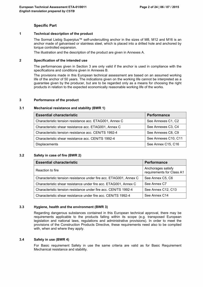
Specific Part
1 Technical description of the product
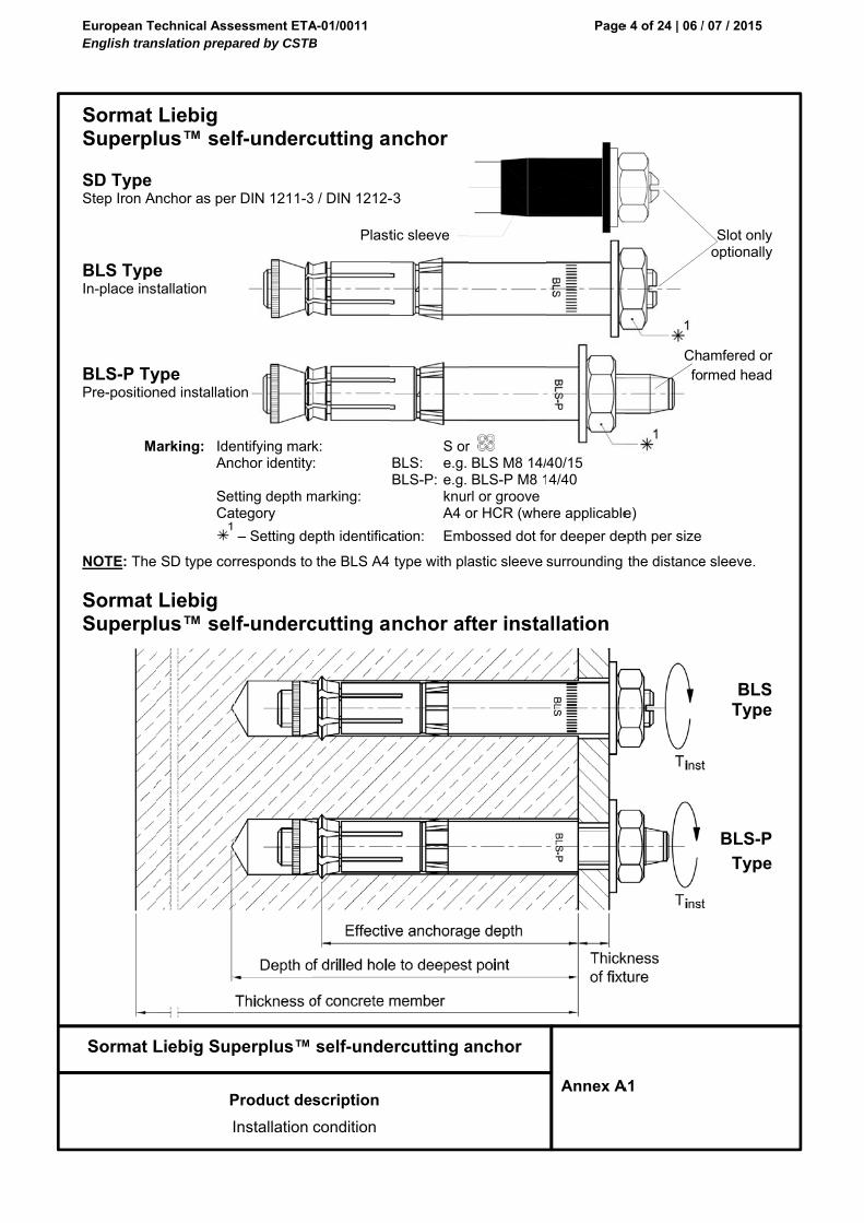
The Sormat Liebig Superplus™ self-undercutting anchor in the sizes of M8, M12 and M16 is an anchor made of galvanised or stainless steel, which is placed into a drilled hole and anchored by torque controlled expansion.
The illustration and the description of the product are given in Annexes A.
2 Specification of the intended use
The performances given in Section 3 are only valid if the anchor is used in compliance with the specifications and conditions given in Annexes B.
The provisions made in this European technical assessment are based on an assumed working life of the anchor of 50 years. The indications given on the working life cannot be interpreted as a guarantee given by the producer, but are to be regarded only as a means for choosing the right products in relation to the expected economically reasonable working life of the works.
3 Performance of the product
3.1 Mechanical resistance and stability (BWR 1)
Essential characteristic Performance
Characteristic tension resistance acc. ETAG001, Annex C See Annexes C1, C2
Characteristic shear resistance acc. ETAG001, Annex C See Annexes C3, C4
Characteristic tension resistance acc. CEN/TS 1992-4 See Annexes C8, C9
Characteristic shear resistance acc. CEN/TS 1992-4 See Annexes C10, C11
Displacements See Annex C15, C16
3.2 Safety in case of fire (BWR 2)
Essential characteristic Performance
Reaction to fire Anchorages satisfy requirements for Class A1
Characteristic tension resistance under fire acc. ETAG001, Annex C See Annex C5, C6
Characteristic shear resistance under fire acc. ETAG001, Annex C See Annex C7
Characteristic tension resistance under fire acc. CEN/TS 1992-4 See Annex C12, C13
Characteristic shear resistance under fire acc. CEN/TS 1992-4 See Annex C14
3.3 Hygiene, health and the environment (BWR 3)
Regarding dangerous substances contained in this European technical approval, there may be requirements applicable to the products falling within its scope (e.g. transposed European legislation and national laws, regulations and administrative provisions). In order to meet the provisions of the Construction Products Directive, these requirements need also to be complied with, when and where they apply.
3.4 Safety in use (BWR 4)
For Basic requirement Safety in use the same criteria are valid as for Basic Requirement Mechanical resistance and stability.
European Technical Assessment ETA-01/0011 English translation prepared by CSTB
Page 3 of 24 | 06 / 07 / 2015
3.5 Protection against noise (BWR 5)
Not relevant.
3.6 Energy economy and heat retention (BWR 6)
Not relevant.
3.7 Sustainable use of natural resources (BWR 7)
For the sustainable use of natural resources no performance was determined for this product.
3.8 General aspects relating to fitness for use
Durability and Serviceability are only ensured if the specifications of intended use according to Annex B1 are kept.
4 Assessment and verification of constancy of performance (AVCP)
According to the Decision 96/582/EC of the European Commission1, as amended, the system of assessment and verification of constancy of performance (see Annex V to Regulation (EU) No 305/2011) given in the following table apply.
Product Intended use Level
or Class System
Metal anchors for use in concrete
For fixing and/or supporting to concrete, structural elements (which contributes to the stability of the works) or heavy units
― 1
5 Technical details necessary for the implementation of the AVCP system
Technical details necessary for the implementation of the Assessment and verification of constancy of performance (AVCP) system are laid down in the control plan deposited at Centre Scientifique et Technique du Bâtiment.
The manufacturer shall, on the basis of a contract, involve a notified body approved in the field of anchors for issuing the certificate of conformity CE based on the control plan.
Issued in Marne La Vallée on 06-07-2015 by
Charles Baloche The original French version is signed
Directeur technique
1 Official Journal of the European Communities L 254 of 08.10.1996
European TeEnglish tran
Sormat L
Sormat Superpl SD Type Step Iron An
BLS TypeIn-place ins
BLS-P TyPre-position
M
NOTE: The
Sormat Superpl
echnical Assnslation prepa
Liebig Sup
P
I
Liebig lus™ sel
nchor as per
e stallation
ype ned installatio
arking: IdeAn SeCa
SD type cor
Liebig lus™ sel
essment ETAared by CSTB
perplus™
Product de
Installation
lf-underc
r DIN 1211-3
on
entifying marchor identity
tting depth mategory
– Setting de
rresponds to
lf-underc
A-01/0011 B
self-unde
scription
condition
cutting a
3 / DIN 1212-
Plast
k: :
marking:
epth identifica
the BLS A4
cutting a
ercutting a
nchor
-3
tic sleeve
S orBLS: e.g.BLS-P: e.g. knur A4 o
ation: Emb
type with pla
nchor af
anchor
r BLS M8 14/BLS-P M8 1
rl or grooveor HCR (whe
bossed dot fo
astic sleeve
fter insta
Page
Annex A
40/15 4/40
ere applicable
or deeper de
surrounding
allation
e 4 of 24 | 06 /
A1
Chfo
e)
epth per size
the distance
/ 07 / 2015
Slot only optionally
amfered or rmed head
e sleeve.
BLSType
BLS-P
Type
European TeEnglish tran
Sormat L
Sormat Superpl
BLS
Table A1
Part De
1 Th
2 Co
3 An
4 Pla
5 Dis
6 Wa
7 He
8 Gr1) Coating: Pa
Table A2
Part De
1 Th
2 Co
3 An
4 Pla
5 Dis
6 Wa
7 He
8 Gr
9 Pla
echnical Assnslation prepa
Liebig Sup
P
Liebig lus™ sel
S Type
: Materials
esignation
hreaded bolt
one
nchor sleeve
astic ring
stance sleev
asher
exagonal nut
rip (only BLS
arts 1 - 3 and
: Materials
esignation
hreaded bolt
one
nchor sleeve
astic ring
stance sleev
asher
exagonal nut
rip (only BLS
astic sleeve
essment ETAared by CSTB
perplus™
Product de
Mater
lf-underc
BLS-P Ty
s BLS and
EN I
Carb
Carb
PE
ve Carb
Carb
t EN I
S-P) Drop
5 - 7 zinc elec
s BLS A4/
EN 1
EN 1
EN 1
PE
ve EN 1
EN 1
t EN 1
S-P) Drop
PA;
A-01/0011 B
self-unde
scription
rials
cutting a
ype
d BLS-P
ISO 898-1; p
bon steel
bon steel
bon steel; fu ≥
bon steel EN
ISO 898-2; p
p of glue, tap
ctroplated acc
/HCR, BLS
10088: 1.440
10088: 1.440
10088: 1.440
10088: 1.440
10088: 1.440
10088: 1.440
p of glue, tap
DIN EN ISO
ercutting a
nchor
Mater
property class
≥ 500 N/mm
N 10139
property class
pe or rubber
cording EN ISO
S-P A4/HC
Materia
01 / 1.4404 /
01 / 1.4404 /
01 / 1.4404 /
01 / 1.4404 /
01 / 1.4404 /
01 / 1.4404 /
pe or rubber
O 1874-1
anchor
rial: Zinc ele
s 8.8
²
s 8
O-Ring
O 4042 ≥ 5µm
CR and SD
al: Stainless
1.4571 / 1.4
1.4571 / 1.4
1.4571 / 1.4
1.4571 / 1.4
1.4571 / 1.4
1.4571 / 1.4
O-Ring
Ty
Page
Annex A
ectroplated 1
, passivated.
steel A4/HC
4529; EN ISO
4529
4529
4529; fu ≥ 500
4529
4529; EN ISO
ype SD on
e 5 of 24 | 06 /
A2
1)
CR
O 3506-1: A4
0 N/mm²
O 3506-2: A4
ly
9
/ 07 / 2015
4-80
4-80
European Technical Assessment ETA-01/0011 English translation prepared by CSTB
Page 6 of 24 | 06 / 07 / 2015
Sormat Liebig Superplus™ self-undercutting anchor
Intended Use
Specifications
Annex B1
Specifications of intended use
Anchorages subject to: Static, quasi-static and loads under fire
Base materials: Cracked and Non-cracked concrete Reinforced or unreinforced normal weight concrete of strength classes C 20/25 at least to C50/60
at most according to EN 206: 2000-12
Use conditions (Environmental conditions): The BLS and BLS-P anchors may only be used in structures subject to dry indoor conditions,
indoor with temporary condensation. The BLS A4 and BLS-P A4 may be used in concrete subject to dry internal conditions and also in
concrete subject to external atmospheric exposure (including industrial and marine environment), or exposure in permanently damp internal conditions, if no particular aggressive conditions exist.
The BLS HCR and BLS-P HCR may be used in concrete subject to dry internal conditions and also in concrete subject to external atmospheric exposure, in permanently damp internal conditions or in other particular aggressive conditions.
Note: Particular aggressive conditions are e.g. permanent, alternating immersion in seawater or the splash zone of seawater, chloride atmosphere of indoor swimming pools or atmosphere with extreme chemical pollution (e.g. in desulphurization plants or road tunnels where de-icing materials are used).
Design: The anchorages are designed in accordance with the ETAG001 Annex C “Design Method for
Anchorages” or CEN/TS 1992-4-4 "Design of fastenings for use in concrete” under the responsibility of an engineer experienced in anchorages and concrete work.
For application with resistance under fire exposure the anchorages are designed in accordance with method given in TR020 “Evaluation of Anchorage in Concrete concerning Resistance to Fire”.
Verifiable calculation notes and drawings are prepared taking account of the loads to be anchored. The position of the anchor is indicated on the design drawings.
Installation: Anchor installation carried out by appropriately qualified personnel and under the supervision of the
person responsible for technical matters of the site. Use of the anchor only as supplied by the manufacturer without exchanging the components of an
anchor. Anchor installation in accordance with the manufacturer’s specifications and drawings and using
the appropriate tools. Effective anchorage depth, edge distances and spacing not less than the specified values without
minus tolerances. Hole drilling by hammer drill. Cleaning of the hole of drilling dust BLS version installed through fixture using an ordinary hammer and tightened to specified torque. BLS-P version installed into drill-hole using an ordinary hammer. Then, nut and washer are
removed, fixture installed, washer and nut installed, and tightened to specified torque. Application of specified torque moment using a calibrated torque tool In case of aborted hole, drilling of new hole at a minimum distance of twice the depth of the aborted
hole, or smaller distance provided the aborted drill hole is filled with high strength mortar and no shear or oblique tension loads in the direction of aborted hole.
B
B
B
B
B
B
B
B
B
B
B
B
European TeEnglish tran
Sormat L
Sormat Superpl
Table B1
M
An
BLS M8 - 14
BLS-P M8 -
BLS M8 - 14
BLS-P M8 -
BLS M12 - 2
BLS-P M12
BLS M12 - 2
BLS-P M12
BLS M16 - 2
BLS-P M16
BLS M16 - 2
BLS-P M16
echnical Assnslation prepa
Liebig Sup
Liebig lus™ sel
: Anchor
Main dimensio
nchor type
4/40 (A4/HCR
14/40 (A4/H
4/80 (A4/HC
- 14/80 (A4/H
20/80 (A4/HC
- 20/80 (A4/
20/150 (A4/H
- 20/150 (A4
25/150 (A4/H
- 25/150 (A4
25/200 (A4/H
- 25/200 (A4
essment ETAared by CSTB
perplus™
Intended
Anchor dim
lf-underc
dimensio
ons
tfi[mm
R) 0 10CR)
CR) 0 15HCR)
CR) 0 20/HCR)
HCR) 0 254/HCR)
HCR) 0 254/HCR)
HCR) 0 304/HCR)
A-01/0011 B
self-unde
d Use
mensions
cutting a
ns
ConeAsl
x lc m] [mm]
-00
11.8
-50
11.8
-00
16.5
-50
16.5
-50
17.8
-00
17.8
ercutting a
nchor
nchor leeve
Plastring
ls lp[mm] [mm]
26 6.0
26 6.0
40 11.5
40 11.5
60 11.5
60 11.5
anchor
tic g
Distancesleeve
ld ] [mm]
9-109
9
49-199
49
5 30-230
30
5 100-350
100
5 80-330
80
5 130-430
130
Page
Annexe
e Wash
≥ s ≥ d[mm] [mm
1.5 20
1.5 20
3.5 30
3.5 30
4.0 40
4.0 40
e 7 of 24 | 06 /
B2
BLS
BLS-P
her He
d2 d1 ≥m] [mm] [m
0 8.4 6
0 8.4 6
0 13.0 1
0 13.0 1
0 17.0 1
0 17.0 1
/ 07 / 2015
S Type
P Type
exagonal nut
≥ m ≥ SWmm] [mm]
6.5 13
6.5 13
0.0 18
0.0 18
3.0 24
3.0 24
t
European Technical Assessment ETA-01/0011 English translation prepared by CSTB
Page 8 of 24 | 06 / 07 / 2015
Annexe B3
Sormat Liebig Superplus™ self-undercutting anchor
Intended Use
Installation data
Sormat Liebig Superplus™ self-undercutting anchor
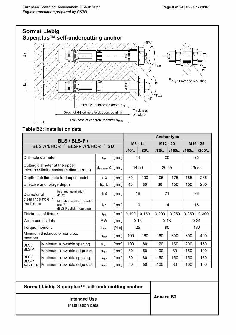
Table B2: Installation data
BLS / BLS-P / BLS A4/HCR / BLS-P A4/HCR / SD
Anchor type
M8 - 14 M12 - 20 M16 - 25
/40/.. /80/.. /80/.. /150/.. /150/.. /200/..
Drill hole diameter do [mm] 14 20 25
Cutting diameter at the upper tolerance limit (maximum diameter bit)
dcut,max ≤ [mm] 14.50 20.55 25.55
Depth of drilled hole to deepest point h1 ≥ [mm] 60 100 105 175 185 235
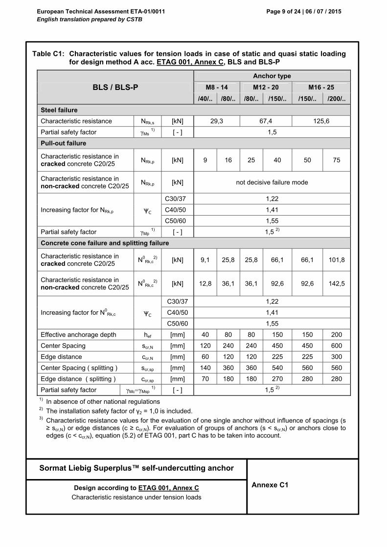
1) In absence of other national regulations 2) The installation safety factor of γ2 = 1,0 is included. 3) Characteristic resistance values for the evaluation of one single anchor without influence of spacings (s ≥ scr,N) or edge distances (c ≥ ccr,N). For evaluation of groups of anchors (s < scr,N) or anchors close to edges (c < ccr,N), equation (5.2) of ETAG 001, part C has to be taken into account.
European Technical Assessment ETA-01/0011 English translation prepared by CSTB
Page 10 of 24 | 06 / 07 / 2015
Sormat Liebig Superplus™ self-undercutting anchor
Design according to ETAG 001, Annex C
Characteristic resistance under tension loads
Annexe C2
Table C2: Characteristic values for tension loads in case of static and quasi static loading for
design method A acc. ETAG 001, Annex C, BLS A4/HCR, BLS-P A4/HCR and SD
1) In absence of other national regulations 2) The installation safety factor of γ2 = 1,0 is included. 3) Characteristic resistance values for the evaluation of one single anchor without influence of spacings (s ≥ scr,N) or edge distances (c ≥ ccr,N). For evaluation of groups of anchors (s < scr,N) or anchors close to edges (c < ccr,N), equation (5.2) of ETAG 001, part C has to be taken into account.
European Technical Assessment ETA-01/0011 English translation prepared by CSTB
Page 11 of 24 | 06 / 07 / 2015
Sormat Liebig Superplus™ self-undercutting anchor
Design according to ETAG 001, Annex C
Characteristic resistance under shear loads
Annex C3
Table C3: Characteristic values for shear loads in case of static and quasi static loading
for design method A acc. ETAG 001, Annex C, BLS and BLS-P
BLS / BLS-P
Anchor type
M8 - 14 M12 - 20 M16 - 25
/40/.. /80/.. /80/.. /150/.. /150/.. /200/..
Steel failure without lever arm
BLS
Characteristic resistance for In-place installation
VRk,s [kN] 41,4 70,0 118,0
Partial safety factor γMs 1) [ - ] 1,25
BLS-P
Characteristic resistance for Pre-positioned installation
Factor in equation ( 5.6 ) of ETAG Annex C, § 5.2.3.3
k [ - ] 1 2 2 2
Partial safety factor γMc 1) [ - ] 1,5 2)
Concrete edge failure
Effective length of anchor under shear load f [mm] 40 80 80 150 150 200
Outside diameter of anchor dnom [mm] 14 20 25
Cracked concrete without any edge reinforcement
Ψucr,V [ - ]
1,00
Cracked concrete with straight edge reinforcement > Ø12 mm
1,20
Cracked concrete with edge reinforcement and closely spaced stirrups (a≤100mm) or non-cracked concrete
1,40
Partial safety factor γMc 1) [ - ] 1,5 2)
1) In absence of other national regulations 2) The installation safety factor of γ2 = 1,0 is included.
European Technical Assessment ETA-01/0011 English translation prepared by CSTB
Page 13 of 24 | 06 / 07 / 2015
Sormat Liebig Superplus™ self-undercutting anchor
Design according to ETAG 001, Annex C
Characteristic tension resistance under fire exposure
Annex C5
Table C5: Characteristic tension resistance under fire exposure for design method A according to ETAG 001, Annex C, BLS, BLS-P, BLS A4/HCR, BLS-P A4/HCR and SD
BLS / BLS-P / BLS A4/HCR / BLS-P A4/HCR / SD
Anchor size (hef,min)
M8 - 14/40 M12 - 20/80 M16 - 25/150
Steel failure
Characteristic resistance NRk,s,fi
BLS / BLS-P
R30 [kN] 0,37 1,70 3,10
R60 [kN] 0,33 1,30 2,30
R90 [kN] 0,26 1,10 0,84
R120 [kN] 0,18 0,84 1,60
BLS / BLS-P A4/HCR
R30 [kN] 0,73 2,5 4,7
R60 [kN] 0,59 2,1 3,9
R90 [kN] 0,44 1,7 3,1
R120 [kN] 0,37 1,3 2,5
Pull-out failure
Characteristic resistance NRk,p,fi
BLS / BLS-P
R30 [kN] 2,3 6,3 12,5
R60 [kN] 2,3 6,3 12,5
R90 [kN] 2,3 6,3 12,5
R120 [kN] 1,8 5,0 10,0
BLS / BLS-P A4/HCR
R30 [kN] 2,3 6,3 15,0
R60 [kN] 2,3 6,3 15,0
R90 [kN] 2,3 6,3 15,0
R120 [kN] 1,8 5,0 12,0
Concrete cone and splitting failure 1)
Characteristic resistance NRk,c,fi
R30 [kN] 1.8 10,3 49,6
R60 [kN] 1.8 10,3 49,6
R90 [kN] 1.8 10,3 49,6
R120 [kN] 1.5 8,2 39,7
Spacing scr,N,fi [mm] 4 x hef
smin [mm] 80 150 150
Edge distance
ccr,N,fi [mm] 2 x hef
cmin [mm] Fire attack from one side: cmin = 2 x hef Fire attack from more than one side: cmin ≥ 300 mm and ≥ 2 x hef
1) As a rule, splitting failure can be neglected when cracked concrete and reinforcement is assumed.
Design under fire exposure is performed according to the design method given in TR 020. Under fire exposure usually cracked concrete is assumed. The design equations are given in TR 020 § 2.2.1.
In the absence of other national regulations the partial safety factor for resistance under fire exposure γM,fi = 1,0 is recommended.
European Technical Assessment ETA-01/0011 English translation prepared by CSTB
Page 14 of 24 | 06 / 07 / 2015
Sormat Liebig Superplus™ self-undercutting anchor
Design according to ETAG 001, Annex C
Characteristic tension resistance under fire exposure
Annex C6
Table C6: Characteristic tension resistance under fire exposure for design method A according to ETAG 001, Annex C, BLS, BLS-P, BLS A4/HCR, BLS-P A4/HCR and SD
BLS / BLS-P / BLS A4/HCR / BLS-P A4/HCR / SD
Anchor size (hef,max)
M8 - 14/80 M12 - 20/150 M16 - 25/200
Steel failure
Characteristic resistance NRk,s,fi
BLS / BLS-P
R30 [kN] 0,37 1,70 3,10
R60 [kN] 0,33 1,30 2,30
R90 [kN] 0,26 1,10 0,84
R120 [kN] 0,18 0,84 1,60
BLS / BLS-P A4/HCR
R30 [kN] 0,73 2,5 4,7
R60 [kN] 0,59 2,1 3,9
R90 [kN] 0,44 1,7 3,1
R120 [kN] 0,37 1,3 2,5
Pull-out failure
Characteristic resistance NRk,p,fi
BLS / BLS-P
R30 [kN] 4,0 10,0 18,8
R60 [kN] 4,0 10,0 18,8
R90 [kN] 4,0 10,0 18,8
R120 [kN] 3,2 8,0 15,0
BLS / BLS-P A4/HCR
R30 [kN] 3,0 10,0 15,0
R60 [kN] 3,0 10,0 15,0
R90 [kN] 3,0 10,0 15,0
R120 [kN] 2,4 8,0 12,0
Concrete cone and splitting failure 1)
Characteristic resistance NRk,c,fi
R30 [kN] 10,3 49,6 101,8
R60 [kN] 10,3 49,6 101,8
R90 [kN] 10,3 49,6 101,8
R120 [kN] 8,2 39,7 81,5
Spacing scr,N,fi [mm] 4 x hef
smin [mm] 80 150 180
Edge distance
ccr,N,fi [mm] 2 x hef
cmin [mm] Fire attack from one side: cmin = 2 x hef Fire attack from more than one side: cmin ≥ 300 mm and ≥ 2 x hef
1) As a rule, splitting failure can be neglected when cracked concrete and reinforcement is assumed.
Design under fire exposure is performed according to the design method given in TR 020. Under fire exposure usually cracked concrete is assumed. The design equations are given in TR 020 § 2.2.1.
In the absence of other national regulations the partial safety factor for resistance under fire exposure γM,fi = 1,0 is recommended.
European Technical Assessment ETA-01/0011 English translation prepared by CSTB
Page 15 of 24 | 06 / 07 / 2015
Sormat Liebig Superplus™ self-undercutting anchor
Design according to ETAG 001, Annex C
Characteristic shear resistance under fire exposure
Annex C7
Table C7: Characteristic shear resistance under fire exposure for design method A according to ETAG 001, Annex C, BLS, BLS-P, BLS A4/HCR, BLS-P A4/HCR and SD
The initial value V0Rk,c,fi of the characteristic resistance in concrete C20/25 to C50/60 under fire exposure may
be determined by:
V0Rk,c,fi = 0,25 x V0
Rk,c (≤ R90) V0Rk,c,fi = 0,20 x V0
Rk,c (R120)
with V0Rk,c initial value of the characteristic resistance in cracked concrete C20/25 under normal temperature.
Design under fire exposure is performed according to the design method given in TR 020.
Under fire exposure usually cracked concrete is assumed. The design equations are given in TR 020 § 2.2.1.
TR 020 covers design for fire exposure from one side. For fire attack from more than one side the edge distance must be increased to cmin ≥ 300 mm and ≥ 2 · hef.
In the absence of other national regulations the partial safety factor for resistance under fire exposure γM,fi = 1,0 is recommended.
European Technical Assessment ETA-01/0011 English translation prepared by CSTB
Page 16 of 24 | 06 / 07 / 2015
Sormat Liebig Superplus™ self-undercutting anchor
Design according to CEN/TS 1992-4
Characteristic resistance under tension loads
Annex C8
Table C8: Characteristic values for tension loads in case of static and quasi static loading for design method A according to CEN/TS 1992-4, BLS and BLS-P
1) In absence of other national regulations 2) The installation safety factor of γ2 = 1,0 is included.
European Technical Assessment ETA-01/0011 English translation prepared by CSTB
Page 17 of 24 | 06 / 07 / 2015
Sormat Liebig Superplus™ self-undercutting anchor
Design according to CEN/TS 1992-4
Characteristic resistance under tension loads
Annex C9
Table C9: Characteristic values for tension loads in case of static and quasi static loading for design method A according to CEN/TS 1992-4, BLS A4/HCR, BLS-P A4/HCR and SD
1) In absence of other national regulations 2) The installation safety factor of γ2 = 1,0 is included.
European Technical Assessment ETA-01/0011 English translation prepared by CSTB
Page 18 of 24 | 06 / 07 / 2015
Sormat Liebig Superplus™ self-undercutting anchor
Design according to CEN/TS 1992-4
Characteristic resistance under shear loads
Annex C10
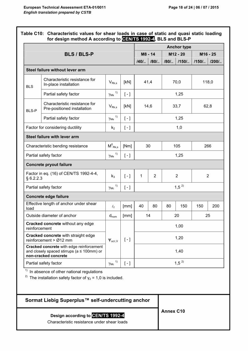
Table C10: Characteristic values for shear loads in case of static and quasi static loading for design method A according to CEN/TS 1992-4, BLS and BLS-P
BLS / BLS-P
Anchor type
M8 - 14 M12 - 20 M16 - 25
/40/.. /80/.. /80/.. /150/.. /150/.. /200/..
Steel failure without lever arm
BLS
Characteristic resistance for In-place installation
VRk,s [kN] 41,4 70,0 118,0
Partial safety factor γMs 1) [ - ] 1,25
BLS-P
Characteristic resistance for Pre-positioned installation
Effective length of anchor under shear load f [mm] 40 80 80 150 150 200
Outside diameter of anchor dnom [mm] 14 20 25
Cracked concrete without any edge reinforcement
Ψucr,V [ - ]
1,00
Cracked concrete with straight edge reinforcement > Ø12 mm
1,20
Cracked concrete with edge reinforcement and closely spaced stirrups (a ≤ 100mm) or non-cracked concrete
1,40
Partial safety factor γMc 1) [ - ] 1,5 2)
1) In absence of other national regulations 2) The installation safety factor of γ2 = 1,0 is included.
European Technical Assessment ETA-01/0011 English translation prepared by CSTB
Page 19 of 24 | 06 / 07 / 2015
Sormat Liebig Superplus™ self-undercutting anchor
Design according to CEN/TS 1992-4
Characteristic resistance under shear loads
Annex C11
Table C11: Characteristic values for shear loads in case of static and quasi static loading for design method A according to CEN/TS 1992-4, BLS A4/HCR, BLS-P A4/HCR and SD
BLS A4/HCR / BLS-P A4/HCR / SD
Anchor type
M8 - 14 M12 - 20 M16 - 25
/40/.. /80/.. /80/.. /150/.. /150/.. /200/..
Steel failure without lever arm
BLS
Characteristic resistance for In-place installation
VRk,s [kN] 44,6 90,3 169,8
Partial safety factor γMs 1) [ - ] 1,33
BLS-P
Characteristic resistance for Pre-positioned installation
Factor in equation ( 5.6 ) of ETAG Annex C, § 5.2.3.3
k3 [ - ] 1 2 2 2
Partial safety factor γMc 1) [ - ] 1,5 2)
Concrete edge failure
Effective length of anchor under shear load f [mm] 40 80 80 150 150 200
Outside diameter of anchor dnom [mm] 14 20 25
Cracked concrete without any edge reinforcement
Ψucr,V [ - ]
1,00
Cracked concrete with straight edge reinforcement > Ø12 mm
1,20
Cracked concrete with edge reinforcement and closely spaced stirrups (a≤100mm) or non-cracked concrete
1,40
Partial safety factor γMc 1) [ - ] 1,5 2)
1) In absence of other national regulations 2) The installation safety factor of γ2 = 1,0 is included.
European Technical Assessment ETA-01/0011 English translation prepared by CSTB
Page 20 of 24 | 06 / 07 / 2015
Sormat Liebig Superplus™ self-undercutting anchor
Design according to CEN/TS 1992-4
Characteristic tension resistance under fire exposure
Annex C12
Table C12: Characteristic tension resistance under fire exposure for design method A according to CEN/TS 1992-4, BLS, BLS-P, BLS A4/HCR, BLS-P A4/HCR and SD
BLS / BLS-P / BLS A4/HCR / BLS-P A4/HCR / SD
Anchor size (hef,min)
M8 - 14/40 M12 - 20/80 M16 - 25/150
Steel failure
Characteristic resistance NRk,s,fi
BLS / BLS-P
R30 [kN] 0,37 1,70 3,10
R60 [kN] 0,33 1,30 2,30
R90 [kN] 0,26 1,10 0,84
R120 [kN] 0,18 0,84 1,60
BLS / BLS-P A4/HCR
R30 [kN] 0,73 2,5 4,7
R60 [kN] 0,59 2,1 3,9
R90 [kN] 0,44 1,7 3,1
R120 [kN] 0,37 1,3 2,5
Pull-out failure
Characteristic resistance NRk,p,fi
BLS / BLS-P
R30 [kN] 2,3 6,3 12,5
R60 [kN] 2,3 6,3 12,5
R90 [kN] 2,3 6,3 12,5
R120 [kN] 1,8 5,0 10,0
BLS / BLS-P A4/HCR
R30 [kN] 2,3 6,3 15,0
R60 [kN] 2,3 6,3 15,0
R90 [kN] 2,3 6,3 15,0
R120 [kN] 1,8 5,0 12,0
Concrete cone and splitting failure 1)
Characteristic resistance NRk,c,fi
R30 [kN] 1.8 10,3 49,6
R60 [kN] 1.8 10,3 49,6
R90 [kN] 1.8 10,3 49,6
R120 [kN] 1.5 8,2 39,7
Spacing scr,N,fi [mm] 4 x hef
smin [mm] 80 150 150
Edge distance
ccr,N,fi [mm] 2 x hef
cmin [mm] Fire attack from one side: cmin = 2 x hef Fire attack from more than one side: cmin ≥ 300 mm and ≥ 2 x hef
1) As a rule, splitting failure can be neglected when cracked concrete and reinforcement is assumed.
Design under fire exposure is performed according to the design method given in TR 020. Under fire exposure usually cracked concrete is assumed. The design equations are given in TR 020 § 2.2.1.
In the absence of other national regulations the partial safety factor for resistance under fire exposure γM,fi = 1,0 is recommended.
European Technical Assessment ETA-01/0011 English translation prepared by CSTB
Page 21 of 24 | 06 / 07 / 2015
Sormat Liebig Superplus™ self-undercutting anchor
Design according to CEN/TS 1992-4
Characteristic tension resistance under fire exposure
Annex C13
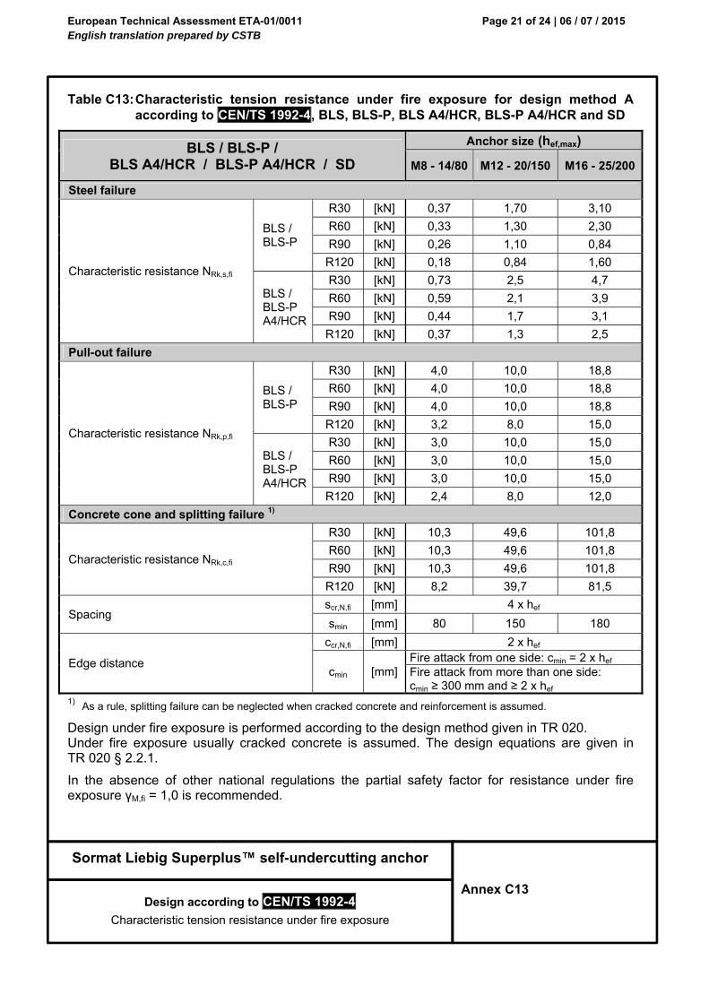
Table C13: Characteristic tension resistance under fire exposure for design method A according to CEN/TS 1992-4, BLS, BLS-P, BLS A4/HCR, BLS-P A4/HCR and SD
BLS / BLS-P / BLS A4/HCR / BLS-P A4/HCR / SD
Anchor size (hef,max)
M8 - 14/80 M12 - 20/150 M16 - 25/200
Steel failure
Characteristic resistance NRk,s,fi
BLS / BLS-P
R30 [kN] 0,37 1,70 3,10
R60 [kN] 0,33 1,30 2,30
R90 [kN] 0,26 1,10 0,84
R120 [kN] 0,18 0,84 1,60
BLS / BLS-P A4/HCR
R30 [kN] 0,73 2,5 4,7
R60 [kN] 0,59 2,1 3,9
R90 [kN] 0,44 1,7 3,1
R120 [kN] 0,37 1,3 2,5
Pull-out failure
Characteristic resistance NRk,p,fi
BLS / BLS-P
R30 [kN] 4,0 10,0 18,8
R60 [kN] 4,0 10,0 18,8
R90 [kN] 4,0 10,0 18,8
R120 [kN] 3,2 8,0 15,0
BLS / BLS-P A4/HCR
R30 [kN] 3,0 10,0 15,0
R60 [kN] 3,0 10,0 15,0
R90 [kN] 3,0 10,0 15,0
R120 [kN] 2,4 8,0 12,0
Concrete cone and splitting failure 1)
Characteristic resistance NRk,c,fi
R30 [kN] 10,3 49,6 101,8
R60 [kN] 10,3 49,6 101,8
R90 [kN] 10,3 49,6 101,8
R120 [kN] 8,2 39,7 81,5
Spacing scr,N,fi [mm] 4 x hef
smin [mm] 80 150 180
Edge distance
ccr,N,fi [mm] 2 x hef
cmin [mm] Fire attack from one side: cmin = 2 x hef Fire attack from more than one side: cmin ≥ 300 mm and ≥ 2 x hef
1) As a rule, splitting failure can be neglected when cracked concrete and reinforcement is assumed.
Design under fire exposure is performed according to the design method given in TR 020. Under fire exposure usually cracked concrete is assumed. The design equations are given in TR 020 § 2.2.1.
In the absence of other national regulations the partial safety factor for resistance under fire exposure γM,fi = 1,0 is recommended.
European Technical Assessment ETA-01/0011 English translation prepared by CSTB
Page 22 of 24 | 06 / 07 / 2015
Sormat Liebig Superplus™ self-undercutting anchor
Design according to CEN/TS 1992-4
Characteristic shear resistance under fire exposure
Annex C14
Table C14: Characteristic shear resistance under fire exposure for design method A according to CEN/TS 1992-4, BLS, BLS-P, BLS A4/HCR, BLS-P A4/HCR and SD
The initial value V0Rk,c,fi of the characteristic resistance in concrete C20/25 to C50/60 under fire exposure may
be determined by:
V0Rk,c,fi = 0,25 x V0
Rk,c (≤ R90) V0Rk,c,fi = 0,20 x V0
Rk,c (R120)
with V0Rk,c initial value of the characteristic resistance in cracked concrete C20/25 under normal temperature.
Design under fire exposure is performed according to the design method given in TR 020.
Under fire exposure usually cracked concrete is assumed. The design equations are given in TR 020 § 2.2.1.
TR 020 covers design for fire exposure from one side. For fire attack from more than one side the edge distance must be increased to cmin ≥ 300 mm and ≥ 2 · hef.
In the absence of other national regulations the partial safety factor for resistance under fire exposure γM,fi = 1,0 is recommended.
European Technical Assessment ETA-01/0011 English translation prepared by CSTB
Page 23 of 24 | 06 / 07 / 2015
Sormat Liebig Superplus™ self-undercutting anchor
Design
Displacements
Annex C15
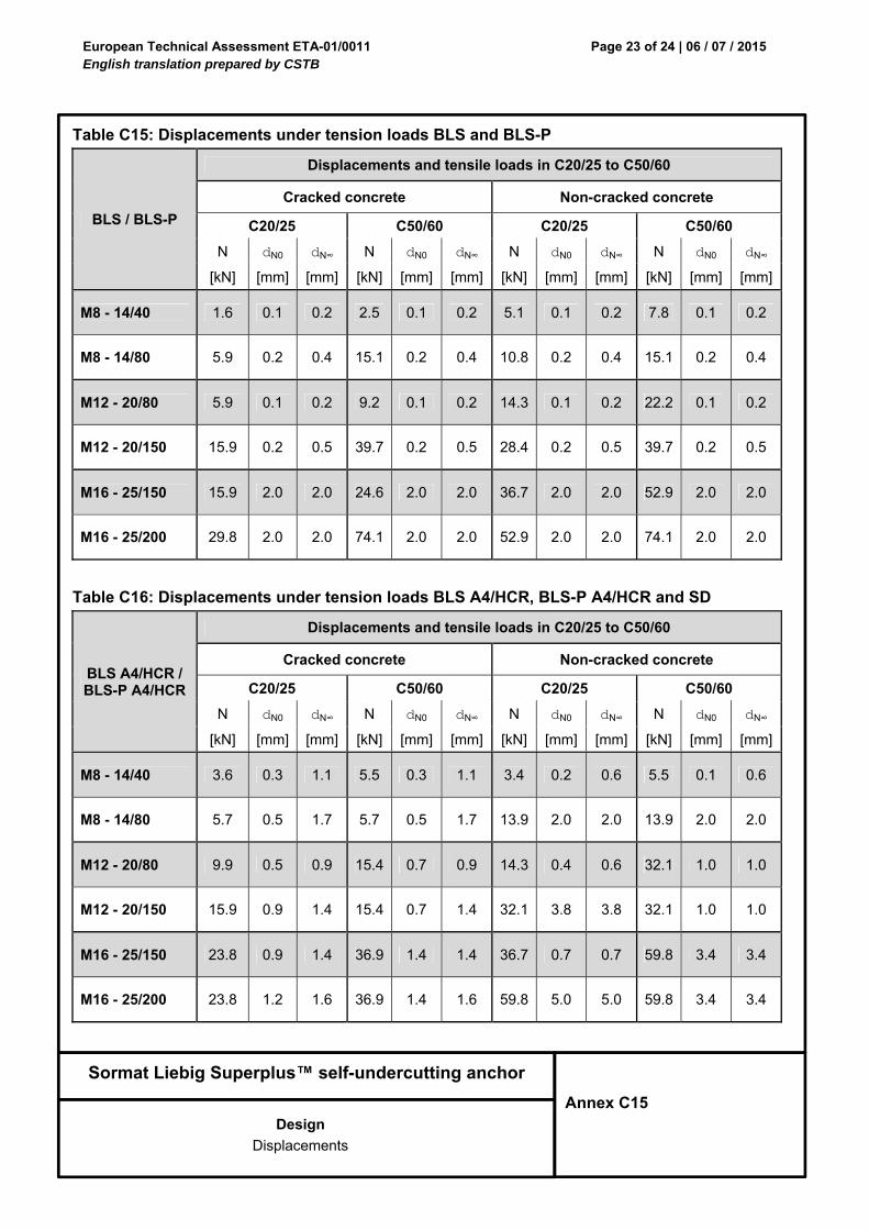
Table C15: Displacements under tension loads BLS and BLS-P
BLS / BLS-P
Displacements and tensile loads in C20/25 to C50/60
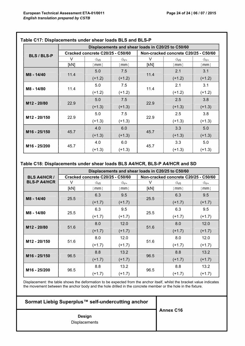
Table C18: Displacements under shear loads BLS A4/HCR, BLS-P A4/HCR and SD
BLS A4/HCR / BLS-P A4/HCR
Displacements and shear loads in C20/25 to C50/60
Cracked concrete C20/25 - C50/60 Non-cracked concrete C20/25 - C50/60 V dV0 dV∞ V dV0 dV∞
[kN] [mm] [mm] [kN] [mm] [mm]
M8 - 14/40 25.5 6.3 9.5
25.5 6.3 9.5
(+1.7) (+1.7) (+1.7) (+1.7)
M8 - 14/80 25.5 6.3 9.5
25.5 6.3 9.5
(+1.7) (+1.7) (+1.7) (+1.7)
M12 - 20/80 51.6 8.0 12.0
51.6 8.0 12.0
(+1.7) (+1.7) (+1.7) (+1.7)
M12 - 20/150 51.6 8.0 12.0
51.6 8.0 12.0
(+1.7) (+1.7) (+1.7) (+1.7)
M16 - 25/150 96.5 8.8 13.2
96.5 8.8 13.2
(+1.7) (+1.7) (+1.7) (+1.7)
M16 - 25/200 96.5 8.8 13.2
96.5 8.8 13.2
(+1.7) (+1.7) (+1.7) (+1.7)
Displacement: the table shows the deformation to be expected from the anchor itself, whilst the bracket value indicates the movement between the anchor body and the hole drilled in the concrete member or the hole in the fixture.