87
Aquafilter
E9_InspectionRecMed_Ing_rev09 – 05/04/11
1
E9
Dear Doctor,
Thank you for the faith that you have shown us by acquiring this series E9 autoclave.
We want you to know that our firm is at your complete disposition to furnish information and to answer any
questions concerning the operation and use of this equipment.
We remind you that for the correct usage of this machine it is necessary to first read this manual. The E9
corresponds to all of the relative safety regulations and presents no danger to the operator when used
according to the instructions.
While wishing you success in your work, we remind you that the reproduction of this manual is forbidden and
that the technical components could be changed without warning due to our continued technical research.
EURONDA S.p.A.
Aquafilter
E9_InspectionRecMed_Ing_rev09 – 05/04/11
2
E9
INDEX
CHAPTER 1 ....................................................................................................................................................... 5 1.1 GUARANTEE ................................................................................................................................ 5 1.2 CERTIFICATE OF GUARANTEE (facsimile) ............................................................................... 5
CHAPTER 2 ....................................................................................................................................................... 6 2.1 REFERENCE STANDARDS ......................................................................................................... 6 2.2 STAFF REQUIREMENTS ............................................................................................................. 6 2.3 USING AND STORING THE MANUAL ........................................................................................ 6 2.4 READING THE MANUAL: SYMBOLS AND CONVENTIONS ...................................................... 7 2.5 HOW TO OBTAIN A NEW COPY OF THE MANUAL .................................................................. 7
CHAPTER 3 ....................................................................................................................................................... 9 3.1 GENERAL SAFETY WARNINGS ................................................................................................. 9 3.2 INTENDED USE ......................................................................................................................... 10 3.3 SAFETY DEVICES ..................................................................................................................... 10 3.4 RESIDUE RISKS ........................................................................................................................ 12 3.5 SAFETY SIGNS ON THE UNIT .................................................................................................. 12 3.6 PERSONAL PROTECTIVE EQUIPMENT (PPE) ....................................................................... 12
CHAPTER 4 ..................................................................................................................................................... 13 4.1 WEIGHT AND DIMENSIONS OF PACKAGING ......................................................................... 13 4.2 RECEIPT AND HANDLING ........................................................................................................ 13 4.3 DESCRIPTION OF CONTENTS ................................................................................................. 13 4.3.1 Optional devices (also see Appendix 10) ................................................................................... 13
CHAPTER 5 ..................................................................................................................................................... 14 5.1 DESCRIPTION OF UNIT ............................................................................................................. 14 5.1.1 Front elements ............................................................................................................................. 14 5.1.2 Rear elements ............................................................................................................................. 14 5.1.3 Upper elements ............................................................................................................................ 15 5.1.4 Description of control panel ......................................................................................................... 15 5.2 OVERALL SPACE REQUIRED ................................................................................................... 16 5.3 TECHNICAL DATA AND NOISE ................................................................................................. 17 5.3.1 Rating plate .................................................................................................................................. 18 5.3.2 Noise level .................................................................................................................................... 18 5.4 INTEGRATED PRINTER ............................................................................................................. 18 5.4.1 Integrated printer for INSPECTION® and MED versions ............................................................. 18 5.4.2 Integrated printer for the RECORDER version ............................................................................ 20
CHAPTER 6 ..................................................................................................................................................... 23 6.1 WORK ENVIRONMENT: POSITIONING..................................................................................... 23 6.2 INSTALLING THE UNIT .............................................................................................................. 24 6.3 ELECTRICAL CONNECTIONS ................................................................................................... 25 6.4 FIRST START-UP ........................................................................................................................ 26 6.5 HOW TO USE THE CONTROL PANEL ...................................................................................... 26 6.5.1 Using the control panel for the INSPECTION® version ............................................................... 26 6.5.2 Using the control panel for the MED version ............................................................................... 28 6.6 INSTALLATION MENU ................................................................................................................ 29 6.7 TANKS: INSTRUCTIONS FOR FILLING AND DRAINING ......................................................... 32
Aquafilter
E9_InspectionRecMed_Ing_rev09 – 05/04/11
3
E9
CHAPTER 7 ..................................................................................................................................................... 35 7.1 PROGRAM MENU ....................................................................................................................... 35 7.2 SELECTING A STERILIZATION CYCLE .................................................................................... 36 7.2.1 Start-up, execution and end of a cycle......................................................................................... 38 7.2.2 Information on process parameters ............................................................................................. 40 7.3 SELECTING A TEST ................................................................................................................... 41 7.3.1 Start-up, execution and end of a test ........................................................................................... 41 7.3.2 Information on test parameters .................................................................................................... 43 7.4 MANUALLY STOPPING A CYCLE OR A TEST ......................................................................... 44 7.4.1 Manually stopping a cycle before or during the sterilization phase ............................................. 44 7.4.2 Manually stopping a cycle after the sterilization phase ................................................................ 45 7.4.3 Manually stopping a test in progress ........................................................................................... 46 7.5 POWER BLACKOUTS ................................................................................................................. 47 7.6 RESETTING THE UNIT AFTER AN INTERRUPTION CAUSED BY AN ALARM ...................... 47 7.7 LONG PERIODS OF INACTIVITY ............................................................................................... 47
CHAPTER 8 ..................................................................................................................................................... 48 8.1 MAIN MENU ................................................................................................................................. 48 8.1.1 Selecting the language ................................................................................................................ 49 8.1.2 User registration ........................................................................................................................... 49 8.1.3 Setting date and time ................................................................................................................... 50 8.1.4 Setting the stand-by time ............................................................................................................. 50 8.1.5 Operators ..................................................................................................................................... 50 8.1.6 Adjusting the contrast on the LCD display ................................................................................... 51 8.1.7 Selecting the unit of measure ...................................................................................................... 51 8.1.8 Selecting active cycles ................................................................................................................. 52 8.1.9 Setting the water supply system .................................................................................................. 53 8.1.10 Setting drying .............................................................................................................................. 53
CHAPTER 9 ..................................................................................................................................................... 54 9.1 SERVICE MENU .......................................................................................................................... 54 9.2 DISPLAYING THE CYCLES PERFORMED (CYCLE COUNTERS) ........................................... 54 9.3 MEMORY AND PRINT FUNCTIONS .......................................................................................... 55 9.3.1 Inactivating the internal printer ..................................................................................................... 56
CHAPTER 10 ................................................................................................................................................... 57 10.1 SAFETY WARNINGS .................................................................................................................. 57 10.2 PERIODIC MAINTENANCE ........................................................................................................ 58 10.2.1 Periodic maintenance .................................................................................................................. 62 10.2.2 Adjusting the closing mechanism ................................................................................................ 63 10.3 EXTRAORDINARY MAINTENANCE ........................................................................................... 64 10.3.1 Rusting ......................................................................................................................................... 66
CHAPTER 11 ................................................................................................................................................... 68 11.1 SCRAPPING INSTRUCTIONS .................................................................................................... 68 11.2 RESALE ....................................................................................................................................... 68
APPENDIX 1 .................................................................................................................................................... 69 Preparing the instruments for sterilization .............................................................................................. 69
APPENDIX 2 .................................................................................................................................................... 70 Packaging ............................................................................................................................................... 70
Aquafilter
E9_InspectionRecMed_Ing_rev09 – 05/04/11
4
E9
APPENDIX 3 .................................................................................................................................................... 71 Positioning the load ................................................................................................................................ 71
APPENDIX 4 .................................................................................................................................................... 72 Unloading and preserving sterilized instruments ................................................................................... 72
APPENDIX 5 .................................................................................................................................................... 73 Description of programs ......................................................................................................................... 73
APPENDIX 6 .................................................................................................................................................... 75 Description of Tests ................................................................................................................................ 75
APPENDIX 7 .................................................................................................................................................... 78 Validating the cycles ............................................................................................................................... 78
APPENDIX 8 .................................................................................................................................................... 79 Quality of process water ......................................................................................................................... 79
APPENDIX 9 .................................................................................................................................................... 80 Troubleshooting ...................................................................................................................................... 80
APPENDIX 10 .................................................................................................................................................. 84 Description of optional devices .............................................................................................................. 84
ANNEX 11 ..................................................................................................................................................... 85 AFNOR block ......................................................................................................................................... 85
Aquafilter
E9_InspectionRecMed_Ing_rev09 – 05/04/11
5
E9
CHAPTER 1
1.1 GUARANTEE Euronda S.p.A. guarantees the quality of its equipment, if used in accordance with the instructions contained in this manual, according to the conditions indicated in the Certificate of Guarantee (see chap. 1.2).
ATTENTION: the CUSTOMER must fill in all parts of the COUPON in the certificate of guarantee and send it to EURONDA S.p.A.
The guarantee period starts from the delivery date of the unit to the customer; this date is confirmed by returning the guarantee slip correctly, duly filled in and signed. In the case of dispute, the date indicated on the purchase invoice, showing the serial number of the unit, will be considered as valid.
1.2 CERTIFICATE OF GUARANTEE (facsimile)
FACSIMILE
Aquafilter
E9_InspectionRecMed_Ing_rev09 – 05/04/11
6
E9
CHAPTER 2
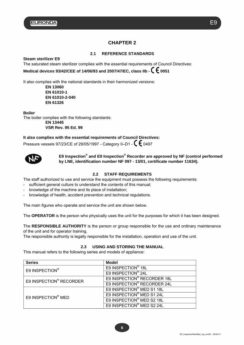
2.1 REFERENCE STANDARDS Steam sterilizer E9 The saturated steam sterilizer complies with the essential requirements of Council Directives:
Medical devices 93/42/CEE of 14/06/93 and 2007/47/EC, class IIb - 0051 It also complies with the national standards in their harmonized versions: EN 13060 EN 61010-1 EN 61010-2-040 EN 61326 Boiler The boiler complies with the following standards: EN 13445 VSR Rev. 95 Ed. 99 It also complies with the essential requirements of Council Directives:
Pressure vessels 97/23/CE of 29/05/1997 - Category II–D1 - 0497
E9 Inspection® and E9 Inspection® Recorder are approved by NF (control performed by LNE, identification number NF 097 - 13/01, certificate number 11634).
2.2 STAFF REQUIREMENTS
The staff authorized to use and service the equipment must possess the following requirements: - sufficient general culture to understand the contents of this manual; - knowledge of the machine and its place of installation; - knowledge of health, accident prevention and technical regulations. The main figures who operate and service the unit are shown below. The OPERATOR is the person who physically uses the unit for the purposes for which it has been designed. The RESPONSIBLE AUTHORITY is the person or group responsible for the use and ordinary maintenance of the unit and for operator training. The responsible authority is legally responsible for the installation, operation and use of the unit.
2.3 USING AND STORING THE MANUAL This manual refers to the following series and models of appliance:
Series Model
E9 INSPECTION® E9 INSPECTION® 18L E9 INSPECTION® 24L
E9 INSPECTION® RECORDER E9 INSPECTION® RECORDER 18L E9 INSPECTION® RECORDER 24L
E9 INSPECTION® MED
E9 INSPECTION® MED S1 18L E9 INSPECTION® MED S1 24L E9 INSPECTION® MED S2 18L E9 INSPECTION® MED S2 24L
Aquafilter
E9_InspectionRecMed_Ing_rev09 – 05/04/11
7
E9
This manual is an integral part of the product and must be kept near the unit for quick and easy consultation. This manual contains instructions for: - correct installation; - the safe and efficient operation of the unit; - continuous and regular maintenance. The unit must be used according to the procedures contained in the manual and only for the purpose for which it was designed. The occupational health and safety directives in force in the Country of destination of the unit must be known and applied in the place of use. The manual must be kept in a safe and easily accessible place for staff; it must also be handled with care. It is forbidden to remove, rewrite or modify the contents of this manual in any way. The drawings and any other documents delivered with the unit may not be divulged to third parties in that Euronda S.p.A. is the sole owner and reserves all rights to them. The partial or total photocopying of the text and illustrations is strictly forbidden. Euronda S.p.A. reserves the right to make modifications or improvements to the manual or equipment without notice and without being obliged to update previous production and manuals. The information contained in this manual refers to the unit the characteristics of which are specified in chap. 5.3.1. “Rating plate”. If the unit is resold, it must be delivered to the new owner together with this manual. In this case, the maker must be informed of the new owner (see chap. 11.2 “Resale”).
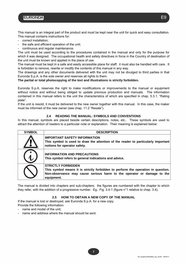
2.4 READING THE MANUAL: SYMBOLS AND CONVENTIONS In this manual, symbols are placed beside certain descriptions, notes, etc.. These symbols are used to attract the attention of readers to a particular note or explanation. Their meaning is explained below:
SYMBOL DESCRIPTION
IMPORTANT SAFETY INFORMATION This symbol is used to draw the attention of the reader to particularly important notions for operator safety.
INFORMATION AND PRECAUTIONS This symbol refers to general indications and advice.
STRICTLY FORBIDDEN This symbol means it is strictly forbidden to perform the operation in question. Non-observance may cause serious harm to the operator or damage to the equipment.
The manual is divided into chapters and sub-chapters; the figures are numbered with the chapter to which they refer, with the addition of a progressive number. Eg.: Fig. 3.4-1 (figure n°1 relative to chap. 3.4).
2.5 HOW TO OBTAIN A NEW COPY OF THE MANUAL If the manual is lost or destroyed, ask Euronda S.p.A. for a new copy. Provide the following information: - name and model of the unit; - name and address where the manual should be sent.
Aquafilter
E9_InspectionRecMed_Ing_rev09 – 05/04/11
8
E9
Send your request to the following address:
EURONDA SPA
Via dell’Artigianato, 7 I- 36030 Montecchio Precalcino
Vicenza - Italy Tel. 0039 – (0)445 329811 Fax 0039 – (0)445 865246 E-mail [email protected]
Aquafilter
E9_InspectionRecMed_Ing_rev09 – 05/04/11
9
E9
CHAPTER 3
3.1 GENERAL SAFETY WARNINGS
Before using the equipment, read the safety information carefully. Non-observance could cause accidents or damage to the machine.
- Before using the unit, operators must have perfectly understood the meanings and functions of all the
controls. - Operators must be aware of and know how to apply the safety regulations governing the use of the unit. - Operators must know and correctly interpret all the indications contained in this manual and those applied
to the unit. - Operators must not perform operations on their own initiative or operations that are not part of their job. - The responsible authority must instruct and train the operator to use and service the unit safely; in
particular, it must ensure that this information has been correctly understood. Particular attention must be paid to the emergency procedure concerning pathogenic materials released
into the atmosphere. This must be written in a special guide stored near the unit. - In the event of malfunctions or potentially dangerous situations, operators MUST immediately report the
situation to the responsible authority. - It is strictly forbidden to use or neutralize the safety devices. - Make sure the unit is powered at the correct voltage. - Make sure the unit is earthed and conforms to the standards applicable in the country of installation. - Never dismantle the unit. - Do not remove the outer safety guard. Even if the unit is not in operation, its cooling fan is always on if
power supply to the machine is connected. Danger of injury to hands (see chap. 3.4 “Residue risks”). - The high voltages inside the unit are dangerous. - If it is not possible to disconnect the power supply, disconnect the mains supply. If this is distant or not
visible by the person carrying out the maintenance work, place the sign, “Work in progress” on the mains switch after it has been turned “OFF”.
- Keep the area around the unit clean and dry. - Do not use solvents on the label. - Do not remove the label on the unit. If necessary, ask for a new one. - Clean the unit with a damp cloth after checking that the power lead is not connected (before using the unit
again, remove any traces of moisture). - Do not pour water onto the unit or any other liquids that could cause short circuits or corrosion. - Do not touch the unit with wet hands or if it is wet; always follow the precautions required for the use of
electrical equipment. - The unit was not designed for use in the presence of gas or explosive vapours. - Do not submit the unit to excessive mechanical stress such as impacts or strong vibrations. - Do not lean over or stand in front of the door when opening it as there is a risk of scalding from escaping
steam (see chap. 3.4. “Residue risks”). - In case of incomplete or unsuccessful sterilisation, the used water in the discharge tank or parts in
contact with the material to sterilise could contain contaminated residues; it is therefore advisable to use protective rubber gloves during draining and handling operations in order to prevent the risk of pathogenic contamination (see chap. 6.7 “Tanks: water filling and draining instructions” and chap. 3.4 “Residue risks”).
- The used water in the discharge tank may, if not properly sterilized, contain contaminated residues: wear latex safety gloves while draining (see chap. 6.7 “Tanks: instructions for filling and emptying” and chap. 3.4. “Residue risks”).
- Before transporting the machine, drain both water tanks. Use the supplied drain tube and follow the instructions for draining (see chap. 6.7 “Tanks: filling and emptying”).
- Before being sterilised, all the materials must be treated as required by current law.
Aquafilter
E9_InspectionRecMed_Ing_rev09 – 05/04/11
10
E9
3.2 INTENDED USE
Steam sterilizer E9: a unit designed and developed for the sterilization of instruments, present in medical, dental, veterinary or podology surgeries, that can be sterilized by steam between 121°C and 134°C. The unit is for professional use only and may only be used by qualified persons. The unit must only be used for the purpose it was designed for.
The manufacturer cannot be held responsible for any breakage, damage or malfunctioning of the unit if the machine has not been used correctly, been used inappropriately or not adequately maintained.
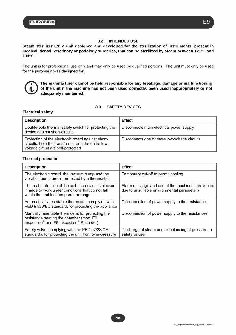
3.3 SAFETY DEVICES Electrical safety
Description Effect
Double-pole thermal safety switch for protecting the device against short-circuits.
Disconnects main electrical power supply
Protection of the electronic board against short-circuits: both the transformer and the entire low-voltage circuit are self-protected
Disconnects one or more low-voltage circuits
Thermal protection
Description Effect
The electronic board, the vacuum pump and the vibration pump are all protected by a thermostat
Temporary cut-off to permit cooling
Thermal protection of the unit: the device is blocked if made to work under conditions that do not fall within the ambient temperature range
Alarm message and use of the machine is prevented due to unsuitable environmental parameters
Automatically resettable thermostat complying with PED 97/23/EC standard, for protecting the appliance
Disconnection of power supply to the resistance
Manually resettable thermostat for protecting the resistance heating the chamber (mod. E9 Inspection® and E9 Inspection® Recorder)
Disconnection of power supply to the resistances
Safety valve, complying with the PED 97/23/CE standards, for protecting the unit from over-pressure
Discharge of steam and re-balancing of pressure to safety values
Aquafilter
E9_InspectionRecMed_Ing_rev09 – 05/04/11
11
E9
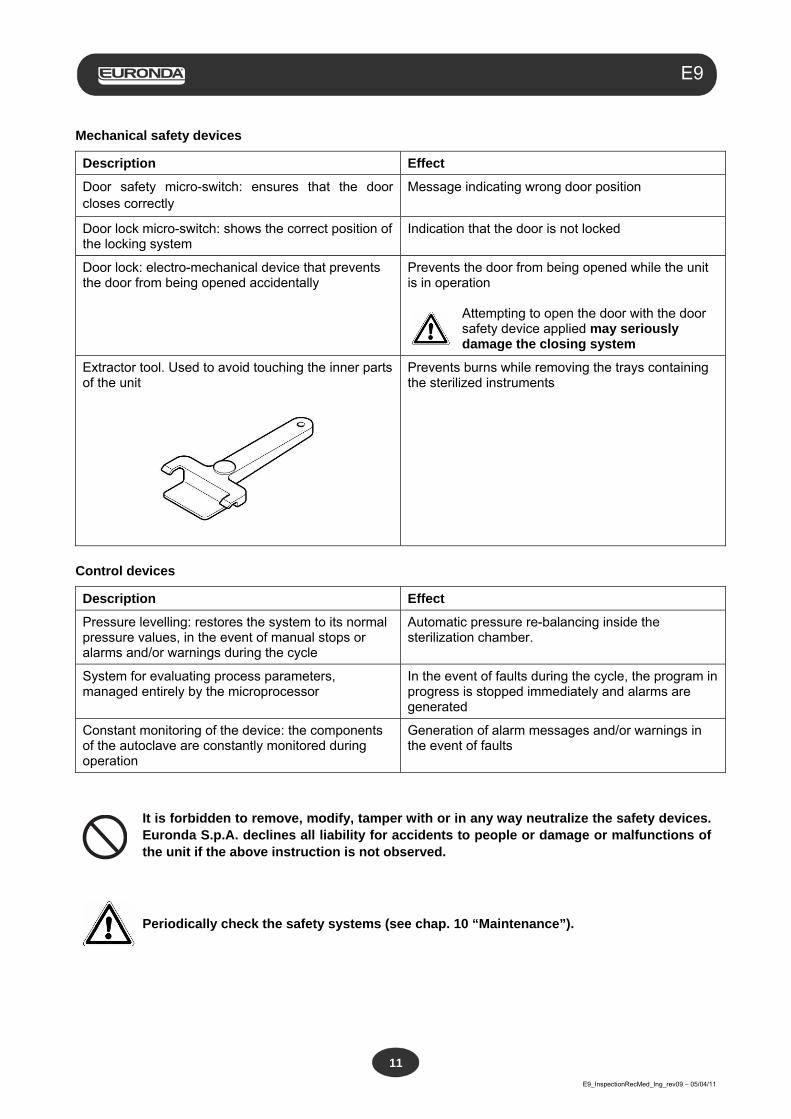
Mechanical safety devices
Description Effect
Door safety micro-switch: ensures that the door closes correctly
Message indicating wrong door position
Door lock micro-switch: shows the correct position of the locking system
Indication that the door is not locked
Door lock: electro-mechanical device that prevents the door from being opened accidentally
Prevents the door from being opened while the unit is in operation
Attempting to open the door with the door safety device applied may seriously damage the closing system
Extractor tool. Used to avoid touching the inner parts of the unit
Prevents burns while removing the trays containing the sterilized instruments
Control devices
Description Effect
Pressure levelling: restores the system to its normal pressure values, in the event of manual stops or alarms and/or warnings during the cycle
Automatic pressure re-balancing inside the sterilization chamber.
System for evaluating process parameters, managed entirely by the microprocessor
In the event of faults during the cycle, the program in progress is stopped immediately and alarms are generated
Constant monitoring of the device: the components of the autoclave are constantly monitored during operation
Generation of alarm messages and/or warnings in the event of faults
It is forbidden to remove, modify, tamper with or in any way neutralize the safety devices. Euronda S.p.A. declines all liability for accidents to people or damage or malfunctions of the unit if the above instruction is not observed.
Periodically check the safety systems (see chap. 10 “Maintenance”).
Aquafilter
E9_InspectionRecMed_Ing_rev09 – 05/04/11
12
E9
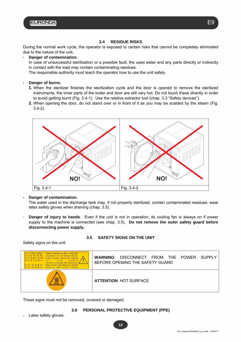
3.4 RESIDUE RISKS
During the normal work cycle, the operator is exposed to certain risks that cannot be completely eliminated due to the nature of the unit. - Danger of contamination. In case of unsuccessful sterilisation or a possible fault, the used water and any parts directly or indirectly
in contact with the load may contain contaminating residues. The responsible authority must teach the operator how to use the unit safely. - Danger of burns. 1. When the sterilizer finishes the sterilization cycle and the door is opened to remove the sterilized
instruments, the inner parts of the boiler and door are still very hot. Do not touch these directly in order to avoid getting burnt (Fig. 3.4-1). Use the relative extractor tool (chap. 3.3 “Safety devices”).
2. When opening the door, do not stand over or in front of it as you may be scalded by the steam (Fig. 3.4-2).
NO!
Fig. 3.4-1 Fig. 3.4-2
- Danger of contamination. The water used in the discharge tank may, if not properly sterilized, contain contaminated residues: wear
latex safety gloves when draining (chap. 3.5). - Danger of injury to hands. Even if the unit is not in operation, its cooling fan is always on if power
supply to the machine is connected (see chap. 3.5). Do not remove the outer safety guard before disconnecting power supply.
3.5 SAFETY SIGNS ON THE UNIT
Safety signs on the unit:
WARNING: DISCONNECT FROM THE POWER SUPPLY BEFORE OPENING THE SAFETY GUARD
ATTENTION: HOT SURFACE
These signs must not be removed, covered or damaged.
3.6 PERSONAL PROTECTIVE EQUIPMENT (PPE) - Latex safety gloves.
NO!
Aquafilter
E9_InspectionRecMed_Ing_rev09 – 05/04/11
13
E9
CHAPTER 4
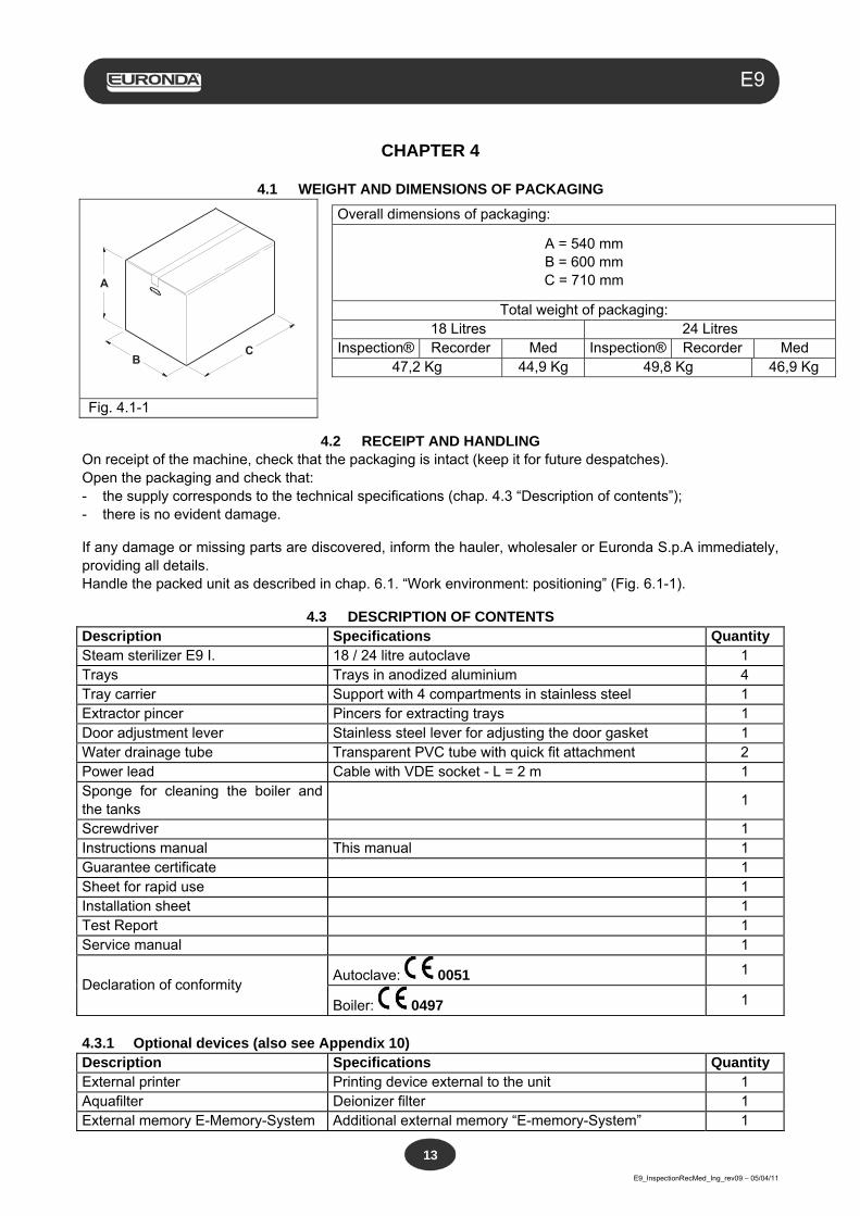
4.1 WEIGHT AND DIMENSIONS OF PACKAGING
CB
A
Fig. 4.1-1
4.2 RECEIPT AND HANDLING On receipt of the machine, check that the packaging is intact (keep it for future despatches). Open the packaging and check that: - the supply corresponds to the technical specifications (chap. 4.3 “Description of contents”); - there is no evident damage.
If any damage or missing parts are discovered, inform the hauler, wholesaler or Euronda S.p.A immediately, providing all details. Handle the packed unit as described in chap. 6.1. “Work environment: positioning” (Fig. 6.1-1).
4.3 DESCRIPTION OF CONTENTS Description Specifications Quantity Steam sterilizer E9 I. 18 / 24 litre autoclave 1 Trays Trays in anodized aluminium 4 Tray carrier Support with 4 compartments in stainless steel 1 Extractor pincer Pincers for extracting trays 1 Door adjustment lever Stainless steel lever for adjusting the door gasket 1 Water drainage tube Transparent PVC tube with quick fit attachment 2 Power lead Cable with VDE socket - L = 2 m 1 Sponge for cleaning the boiler and the tanks
1
Screwdriver 1 Instructions manual This manual 1 Guarantee certificate 1 Sheet for rapid use 1 Installation sheet 1 Test Report 1 Service manual 1
Declaration of conformity Autoclave: 0051 1
Boiler: 0497 1
4.3.1 Optional devices (also see Appendix 10) Description Specifications Quantity External printer Printing device external to the unit 1 Aquafilter Deionizer filter 1 External memory E-Memory-System Additional external memory “E-memory-System” 1
Overall dimensions of packaging:
A = 540 mm B = 600 mm C = 710 mm
Total weight of packaging: 18 Litres 24 Litres
Inspection® Recorder Med Inspection® Recorder Med 47,2 Kg 44,9 Kg 49,8 Kg 46,9 Kg
Aquafilter
E9_InspectionRecMed_Ing_rev09 – 05/04/11
14
E9
CHAPTER 5
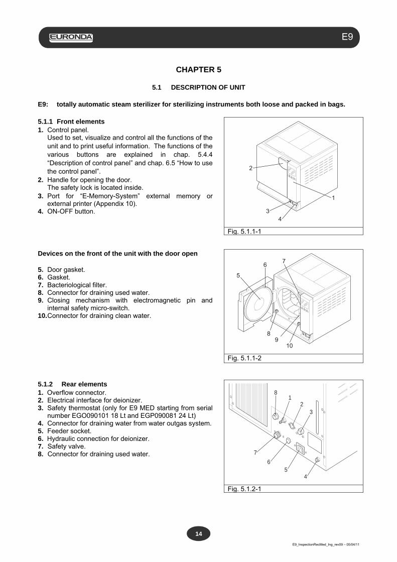
5.1 DESCRIPTION OF UNIT E9: totally automatic steam sterilizer for sterilizing instruments both loose and packed in bags. 5.1.1 Front elements 1. Control panel.
Used to set, visualize and control all the functions of the unit and to print useful information. The functions of the various buttons are explained in chap. 5.4.4 “Description of control panel” and chap. 6.5 “How to use the control panel”.
2. Handle for opening the door. The safety lock is located inside.
3. Port for “E-Memory-System” external memory or external printer (Appendix 10).
4. ON-OFF button.
2
1
34
Fig. 5.1.1-1
Devices on the front of the unit with the door open 5. Door gasket. 6. Gasket. 7. Bacteriological filter. 8. Connector for draining used water. 9. Closing mechanism with electromagnetic pin and
internal safety micro-switch. 10. Connector for draining clean water.
5
6 7
10
89
Fig. 5.1.1-2 5.1.2 Rear elements 1. Overflow connector. 2. Electrical interface for deionizer. 3. Safety thermostat (only for E9 MED starting from serial
number EGO090101 18 Lt and EGP090081 24 Lt) 4. Connector for draining water from water outgas system. 5. Feeder socket. 6. Hydraulic connection for deionizer. 7. Safety valve. 8. Connector for draining used water.
45
67
81
23
Fig. 5.1.2-1
Aquafilter
E9_InspectionRecMed_Ing_rev09 – 05/04/11
15
E9
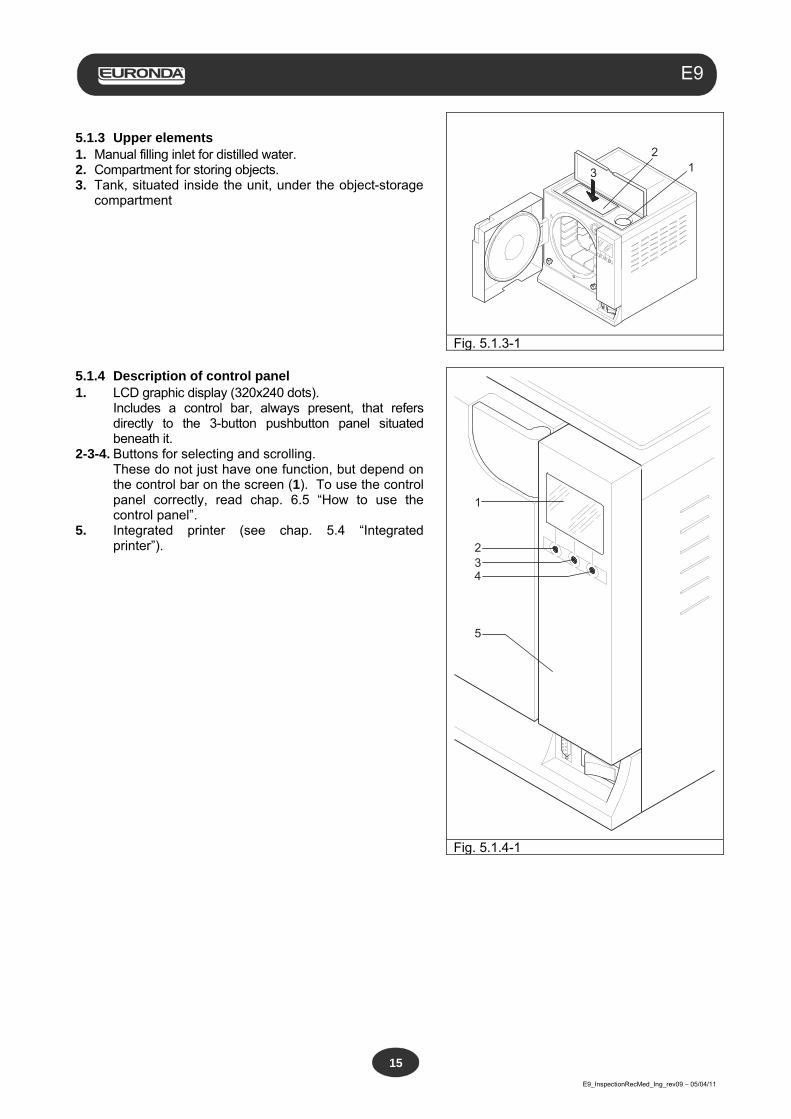
5.1.3 Upper elements 1. Manual filling inlet for distilled water. 2. Compartment for storing objects. 3. Tank, situated inside the unit, under the object-storage
compartment
13
2
Fig. 5.1.3-1 5.1.4 Description of control panel 1. LCD graphic display (320x240 dots). Includes a control bar, always present, that refers
directly to the 3-button pushbutton panel situated beneath it.
2-3-4. Buttons for selecting and scrolling. These do not just have one function, but depend on
the control bar on the screen (1). To use the control panel correctly, read chap. 6.5 “How to use the control panel”.
5. Integrated printer (see chap. 5.4 “Integrated printer”).
1
234
5
Fig. 5.1.4-1
Aquafilter
E9_InspectionRecMed_Ing_rev09 – 05/04/11
16
E9
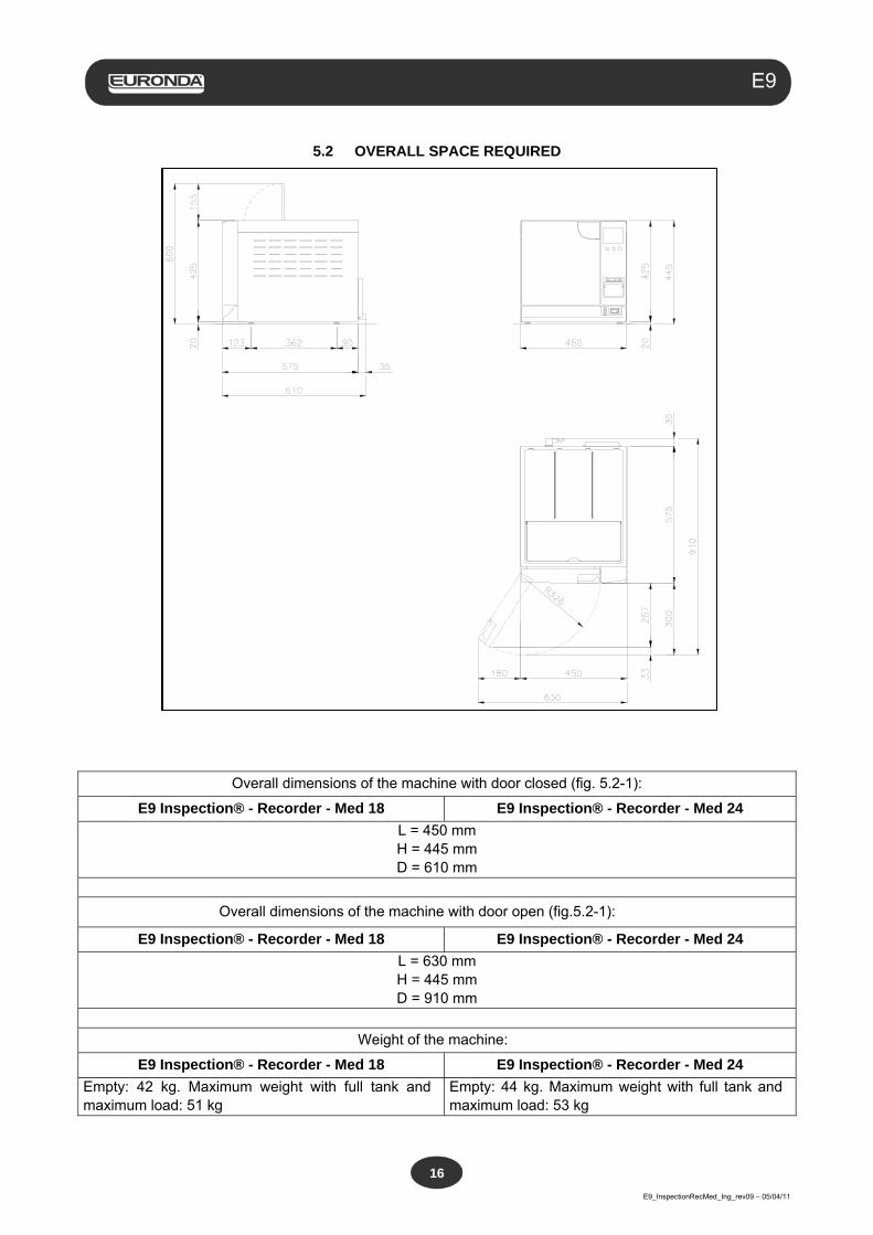
5.2 OVERALL SPACE REQUIRED
Overall dimensions of the machine with door closed (fig. 5.2-1):
E9 Inspection® - Recorder - Med 18 E9 Inspection® - Recorder - Med 24
L = 450 mm H = 445 mm D = 610 mm
Overall dimensions of the machine with door open (fig.5.2-1):
E9 Inspection® - Recorder - Med 18 E9 Inspection® - Recorder - Med 24
L = 630 mm H = 445 mm D = 910 mm
Weight of the machine:
E9 Inspection® - Recorder - Med 18 E9 Inspection® - Recorder - Med 24
Empty: 42 kg. Maximum weight with full tank and maximum load: 51 kg
Empty: 44 kg. Maximum weight with full tank and maximum load: 53 kg
Aquafilter
E9_InspectionRecMed_Ing_rev09 – 05/04/11
17
E9
5.3 TECHNICAL DATA AND NOISE
CHARACTERISTICS E9 Inspection ® - Recorder - Med
18 E9 Inspection ® - Recorder - Med
24
Power supply voltage 230 V
Mains frequency 50 / 60 Hz
Power output 2300 W / 2300 W / 1400 W 2300 W / 2300 W / 1800 W
Absorbed current 10 A 10 A 6 A 10 A 10 A 8 A
Insulation class I / IPX0
Sterilization cycles 5 sterilization cycles
Control cycles Vacuum test - Bowie & Dick test - Helix test
Range of environmental conditions in which the unit was designed to operate
- Indoor use - Altitude up to 2000 m - Temperature: +5 - +40°C - Max. relative humidity 85% - Max. variation in mains voltage: ±10% - Installation category (overvoltage category) II
Maximum pressure * 250 kPa (2.5 bar)
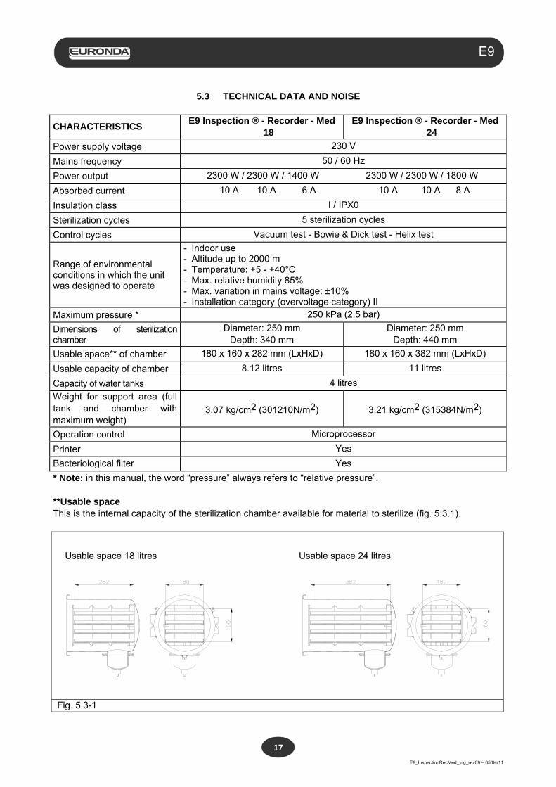
Dimensions of sterilization chamber
Diameter: 250 mm Depth: 340 mm
Diameter: 250 mm Depth: 440 mm
Usable space** of chamber 180 x 160 x 282 mm (LxHxD) 180 x 160 x 382 mm (LxHxD)
Usable capacity of chamber 8.12 litres 11 litres
Capacity of water tanks 4 litres
Weight for support area (full tank and chamber with maximum weight)
3.07 kg/cm2 (301210N/m2) 3.21 kg/cm2 (315384N/m2)
Operation control Microprocessor
Printer Yes
Bacteriological filter Yes
* Note: in this manual, the word “pressure” always refers to “relative pressure”. **Usable space This is the internal capacity of the sterilization chamber available for material to sterilize (fig. 5.3.1).
Fig. 5.3-1
Usable space 18 litres Usable space 24 litres
Aquafilter
E9_InspectionRecMed_Ing_rev09 – 05/04/11
18
E9
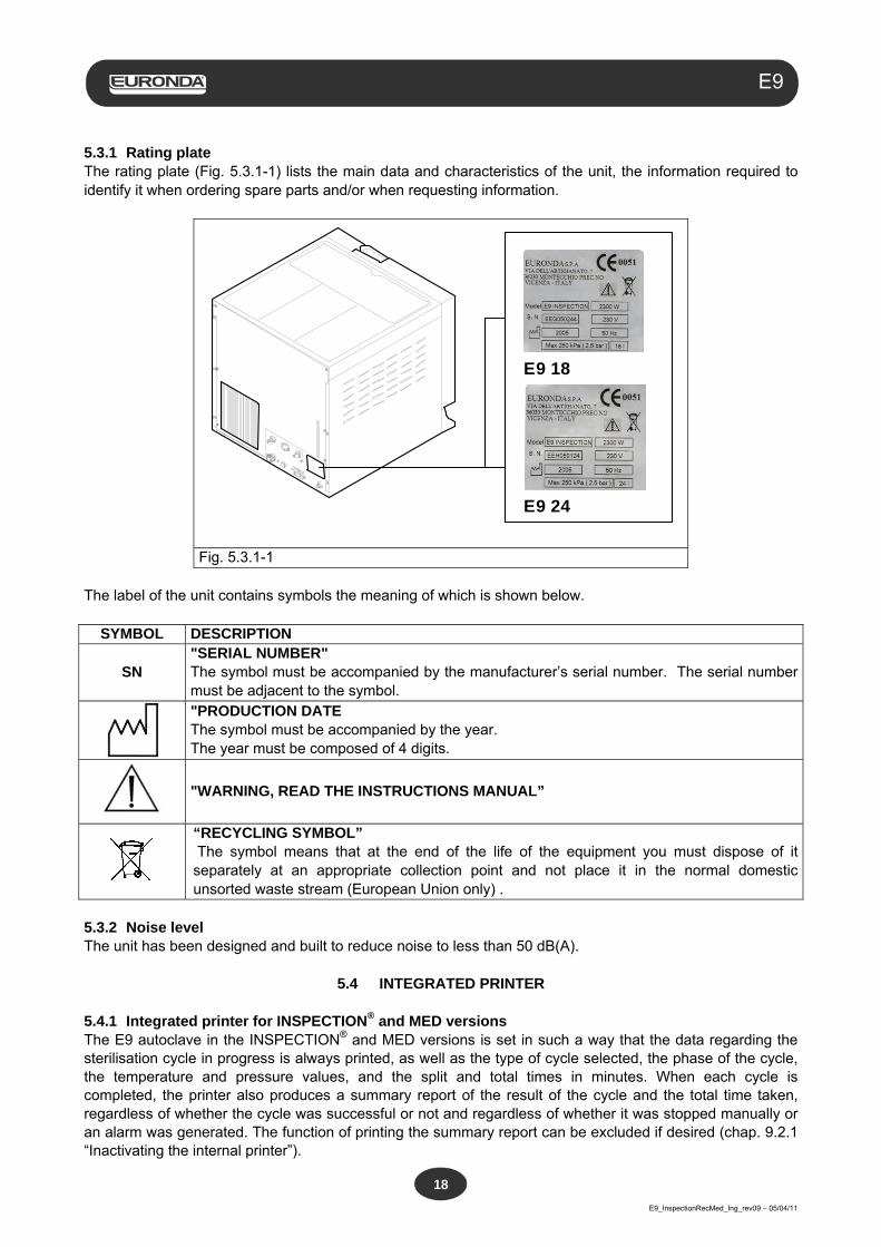
5.3.1 Rating plate The rating plate (Fig. 5.3.1-1) lists the main data and characteristics of the unit, the information required to identify it when ordering spare parts and/or when requesting information.
E9 24
E9 18
Fig. 5.3.1-1 The label of the unit contains symbols the meaning of which is shown below.
SYMBOL DESCRIPTION
SN "SERIAL NUMBER" The symbol must be accompanied by the manufacturer’s serial number. The serial number must be adjacent to the symbol.
"PRODUCTION DATE The symbol must be accompanied by the year. The year must be composed of 4 digits.
"WARNING, READ THE INSTRUCTIONS MANUAL”
“RECYCLING SYMBOL” The symbol means that at the end of the life of the equipment you must dispose of it separately at an appropriate collection point and not place it in the normal domestic unsorted waste stream (European Union only) .
5.3.2 Noise level The unit has been designed and built to reduce noise to less than 50 dB(A).
5.4 INTEGRATED PRINTER 5.4.1 Integrated printer for INSPECTION® and MED versions The E9 autoclave in the INSPECTION® and MED versions is set in such a way that the data regarding the sterilisation cycle in progress is always printed, as well as the type of cycle selected, the phase of the cycle, the temperature and pressure values, and the split and total times in minutes. When each cycle is completed, the printer also produces a summary report of the result of the cycle and the total time taken, regardless of whether the cycle was successful or not and regardless of whether it was stopped manually or an alarm was generated. The function of printing the summary report can be excluded if desired (chap. 9.2.1 “Inactivating the internal printer”).
Aquafilter
E9_InspectionRecMed_Ing_rev09 – 05/04/11
19
E9
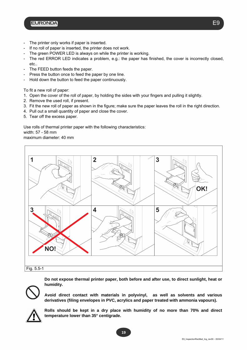
- The printer only works if paper is inserted. - If no roll of paper is inserted, the printer does not work. - The green POWER LED is always on while the printer is working. - The red ERROR LED indicates a problem, e.g.: the paper has finished, the cover is incorrectly closed,
etc.. - The FEED button feeds the paper. - Press the button once to feed the paper by one line. - Hold down the button to feed the paper continuously. To fit a new roll of paper: 1. Open the cover of the roll of paper, by holding the sides with your fingers and pulling it slightly. 2. Remove the used roll, if present. 3. Fit the new roll of paper as shown in the figure; make sure the paper leaves the roll in the right direction. 4. Pull out a small quantity of paper and close the cover. 5. Tear off the excess paper. Use rolls of thermal printer paper with the following characteristics: width: 57 - 58 mm maximum diameter: 40 mm
NO!
1 2 3
3 4 5
OK!
Fig. 5.5-1
Do not expose thermal printer paper, both before and after use, to direct sunlight, heat or humidity. Avoid direct contact with materials in polyvinyl, as well as solvents and various derivatives (filing envelopes in PVC, acrylics and paper treated with ammonia vapours).
Rolls should be kept in a dry place with humidity of no more than 70% and direct temperature lower than 35° centigrade.
Aquafilter
E9_InspectionRecMed_Ing_rev09 – 05/04/11
20
E9
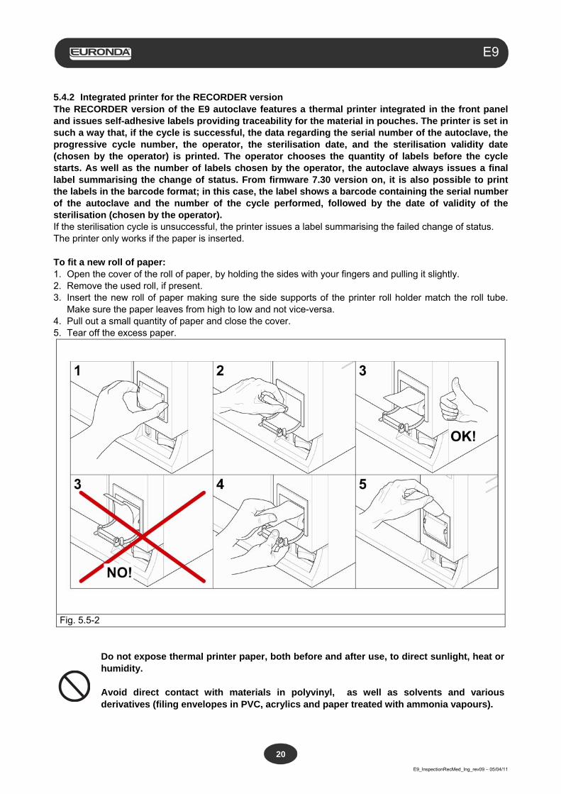
5.4.2 Integrated printer for the RECORDER version The RECORDER version of the E9 autoclave features a thermal printer integrated in the front panel and issues self-adhesive labels providing traceability for the material in pouches. The printer is set in such a way that, if the cycle is successful, the data regarding the serial number of the autoclave, the progressive cycle number, the operator, the sterilisation date, and the sterilisation validity date (chosen by the operator) is printed. The operator chooses the quantity of labels before the cycle starts. As well as the number of labels chosen by the operator, the autoclave always issues a final label summarising the change of status. From firmware 7.30 version on, it is also possible to print the labels in the barcode format; in this case, the label shows a barcode containing the serial number of the autoclave and the number of the cycle performed, followed by the date of validity of the sterilisation (chosen by the operator). If the sterilisation cycle is unsuccessful, the printer issues a label summarising the failed change of status. The printer only works if the paper is inserted. To fit a new roll of paper: 1. Open the cover of the roll of paper, by holding the sides with your fingers and pulling it slightly. 2. Remove the used roll, if present. 3. Insert the new roll of paper making sure the side supports of the printer roll holder match the roll tube.
Make sure the paper leaves from high to low and not vice-versa. 4. Pull out a small quantity of paper and close the cover. 5. Tear off the excess paper.
Fig. 5.5-2
Do not expose thermal printer paper, both before and after use, to direct sunlight, heat or humidity. Avoid direct contact with materials in polyvinyl, as well as solvents and various derivatives (filing envelopes in PVC, acrylics and paper treated with ammonia vapours).
Aquafilter
E9_InspectionRecMed_Ing_rev09 – 05/04/11
21
E9
Rolls should be kept in a dry place with humidity of no more than 70% and direct temperature lower than 35° centigrade.
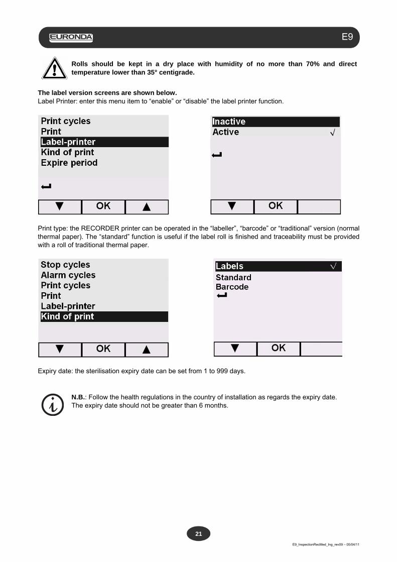
The label version screens are shown below. Label Printer: enter this menu item to “enable” or “disable” the label printer function.
Print type: the RECORDER printer can be operated in the “labeller”, “barcode” or “traditional” version (normal thermal paper). The “standard” function is useful if the label roll is finished and traceability must be provided with a roll of traditional thermal paper.
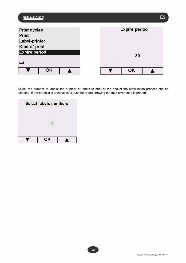
Expiry date: the sterilisation expiry date can be set from 1 to 999 days.
N.B.: Follow the health regulations in the country of installation as regards the expiry date. The expiry date should not be greater than 6 months.
Aquafilter
E9_InspectionRecMed_Ing_rev09 – 05/04/11
22
E9
Select the number of labels: the number of labels to print at the end of the sterilisation process can be selected. If the process is unsuccessful, just the report showing the fault error code is printed.
Aquafilter
E9_InspectionRecMed_Ing_rev09 – 05/04/11
23
E9
CHAPTER 6
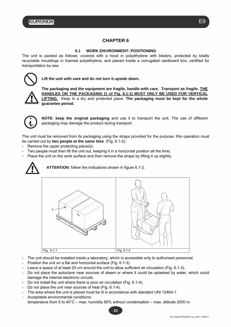
6.1 WORK ENVIRONMENT: POSITIONING The unit is packed as follows: covered with a hood in polyethylene with blisters, protected by totally recyclable mouldings in foamed polyethylene, and placed inside a corrugated cardboard box, certified for transportation by sea.
Lift the unit with care and do not turn it upside down.
The packaging and the equipment are fragile, handle with care. Transport as fragile. THE HANDLES ON THE PACKAGING (1 of Fig. 6.1-1) MUST ONLY BE USED FOR VERTICAL LIFTING. Keep in a dry and protected place. The packaging must be kept for the whole guarantee period.
NOTE: keep the original packaging and use it to transport the unit. The use of different packaging may damage the product during transport.
The unit must be removed from its packaging using the straps provided for the purpose: this operation must be carried out by two people at the same time (Fig. 6.1-2): - Remove the upper protecting piece(s); - Two people must then lift the unit out, keeping it in a horizontal position all the time; - Place the unit on the work surface and then remove the straps by lifting it up slightly.
ATTENTION: follow the indications shown in figure 6.1-2.
1
Fig. 6.1-1 Fig. 6.1-2
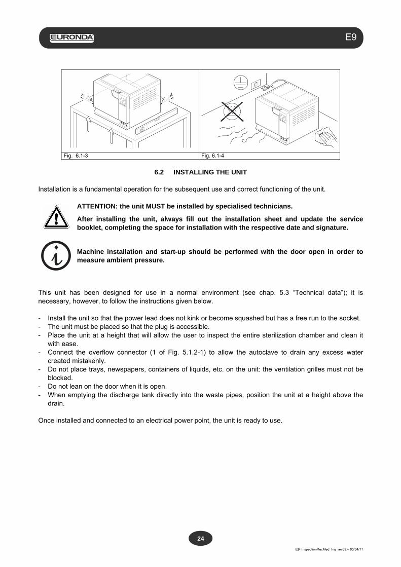
- The unit should be installed inside a laboratory, which is accessible only to authorised personnel. - Position the unit on a flat and horizontal surface (Fig. 6.1-3). - Leave a space of at least 20 cm around the unit to allow sufficient air circulation (Fig. 6.1-3). - Do not place the autoclave near sources of steam or where it could be splashed by water, which could
damage the internal electronic circuits. - Do not install the unit where there is poor air circulation (Fig. 6.1-4). - Do not place the unit near sources of heat (Fig. 6.1-4). - The area where the unit is placed must be lit in accordance with standard UNI 12464-1. - Acceptable environmental conditions: temperature from 5 to 40°C – max. humidity 85% without condensation – max. altitude 2000 m.
Aquafilter
E9_InspectionRecMed_Ing_rev09 – 05/04/11
24
E9
Fig. 6.1-3 Fig. 6.1-4
6.2 INSTALLING THE UNIT
Installation is a fundamental operation for the subsequent use and correct functioning of the unit.
ATTENTION: the unit MUST be installed by specialised technicians.
After installing the unit, always fill out the installation sheet and update the service booklet, completing the space for installation with the respective date and signature.
Machine installation and start-up should be performed with the door open in order to measure ambient pressure.
This unit has been designed for use in a normal environment (see chap. 5.3 “Technical data”); it is necessary, however, to follow the instructions given below. - Install the unit so that the power lead does not kink or become squashed but has a free run to the socket. - The unit must be placed so that the plug is accessible. - Place the unit at a height that will allow the user to inspect the entire sterilization chamber and clean it
with ease. - Connect the overflow connector (1 of Fig. 5.1.2-1) to allow the autoclave to drain any excess water
created mistakenly. - Do not place trays, newspapers, containers of liquids, etc. on the unit: the ventilation grilles must not be
blocked. - Do not lean on the door when it is open. - When emptying the discharge tank directly into the waste pipes, position the unit at a height above the
drain. Once installed and connected to an electrical power point, the unit is ready to use.
Aquafilter
E9_InspectionRecMed_Ing_rev09 – 05/04/11
25
E9
6.3 ELECTRICAL CONNECTIONS
ATTENTION: Electrical connections MUST be made by specialised technicians.
- Check that the power supply voltage indicated on the rear label (Fig. 5.3.1-1) corresponds to that
available at the point of installation. - The unit must be connected with an overload cut-out switch to a system fitted with an adequate earth
system that conforms to the standards applicable in the country of installation. - The system must be connected according to current standards. - Max. variation in mains voltage: +/- 10%. - A differential switch featuring the following characteristics must be installed upstream of the power socket
of the unit: nominal current: 10 A differential sensitivity: 0.03 A. - Connect the supplied cable to the rear of the unit. - Position the unit so that the plug is accessible.
Do not allow the lead to bend tightly and do not place any object on it. Do not use extension leads.
Only use the original lead. ONLY USE ORIGINAL SPARE PARTS.
If the unit does not function correctly, please refer to Appendix 9 “Troubleshooting” of this manual for possible causes. For further information or repairs, please contact your supplier or the technical department of Euronda S.p.A.
WARNING. The unit conforms to the electrical safety requirements of the Standards Institute and comes supplied with a double-pole plug that ensures the unit is earthed. A fundamental safety requirements is to check that the electrical system is adequately earthed and that the capacity of the system and the sockets are suitable for the power of the unit indicated on the label (see chap. 5.3.1 “Rating plate”). Have the system checked by qualified personnel. EURONDA S.p.A DECLINES ALL LIABILITY IF THE ABOVE IS NOT OBSERVED.
Aquafilter
E9_InspectionRecMed_Ing_rev09 – 05/04/11
26
E9
6.4 FIRST START-UP
The unit is packed with the door closed. - Take out the equipment from the sterilization chamber and remove the packaging. - Connect the unit to the power socket following the safety instructions described in chap. 6.3 “Electrical
connections”. - Switch on the unit using the ON-OFF switch (4 of Fig. 5.1.1-1). - After the welcome message, the message “Fill the tank with clean water” appears, that disappears after a
few seconds. For filling, read the instructions in chap. 6.7 “Tanks: instructions for filling and emptying”.
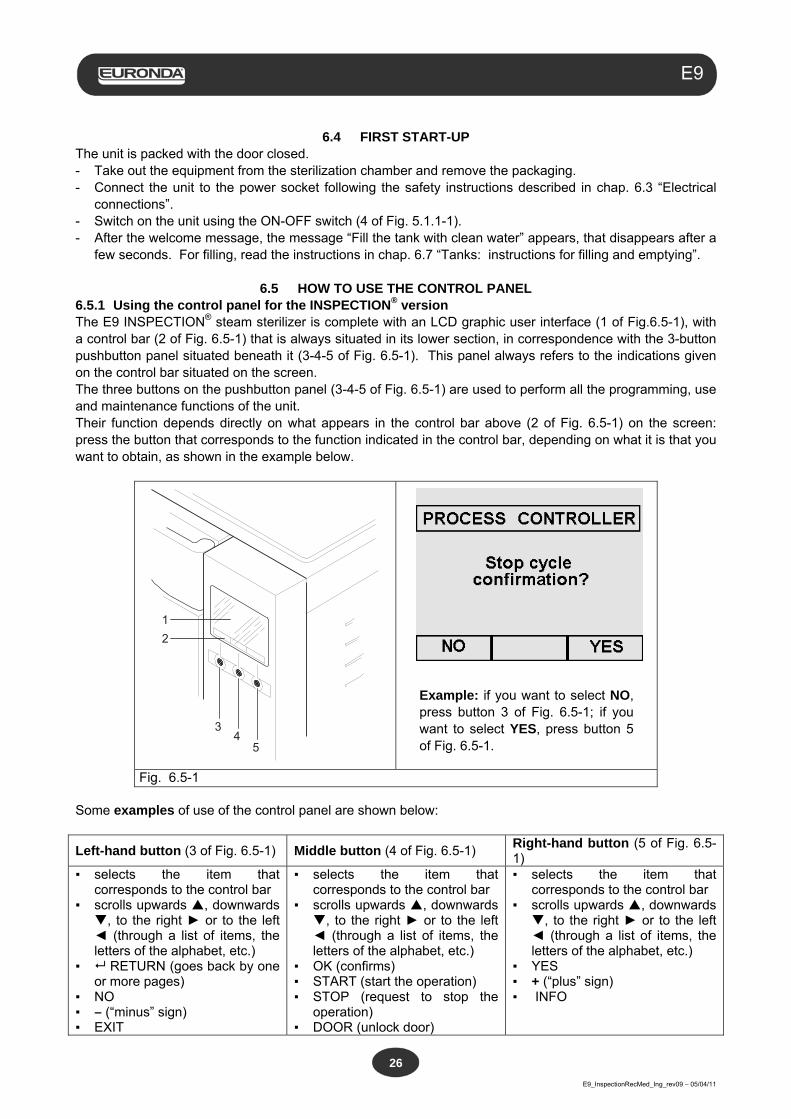
6.5 HOW TO USE THE CONTROL PANEL 6.5.1 Using the control panel for the INSPECTION® version The E9 INSPECTION® steam sterilizer is complete with an LCD graphic user interface (1 of Fig.6.5-1), with a control bar (2 of Fig. 6.5-1) that is always situated in its lower section, in correspondence with the 3-button pushbutton panel situated beneath it (3-4-5 of Fig. 6.5-1). This panel always refers to the indications given on the control bar situated on the screen. The three buttons on the pushbutton panel (3-4-5 of Fig. 6.5-1) are used to perform all the programming, use and maintenance functions of the unit. Their function depends directly on what appears in the control bar above (2 of Fig. 6.5-1) on the screen: press the button that corresponds to the function indicated in the control bar, depending on what it is that you want to obtain, as shown in the example below.
1
5
2
43
Example: if you want to select NO, press button 3 of Fig. 6.5-1; if you want to select YES, press button 5 of Fig. 6.5-1.
Fig. 6.5-1 Some examples of use of the control panel are shown below:
Left-hand button (3 of Fig. 6.5-1) Middle button (4 of Fig. 6.5-1) Right-hand button (5 of Fig. 6.5-1)
▪ selects the item that corresponds to the control bar
▪ scrolls upwards , downwards , to the right ► or to the left ◄ (through a list of items, the letters of the alphabet, etc.)
▪ RETURN (goes back by one or more pages)
▪ NO ▪ – (“minus” sign) ▪ EXIT
▪ selects the item that corresponds to the control bar
▪ scrolls upwards , downwards , to the right ► or to the left ◄ (through a list of items, the letters of the alphabet, etc.)
▪ OK (confirms) ▪ START (start the operation) ▪ STOP (request to stop the
operation) ▪ DOOR (unlock door)
▪ selects the item that corresponds to the control bar
▪ scrolls upwards , downwards , to the right ► or to the left ◄ (through a list of items, the letters of the alphabet, etc.)
▪ YES ▪ + (“plus” sign) ▪ INFO
Aquafilter
E9_InspectionRecMed_Ing_rev09 – 05/04/11
27
E9
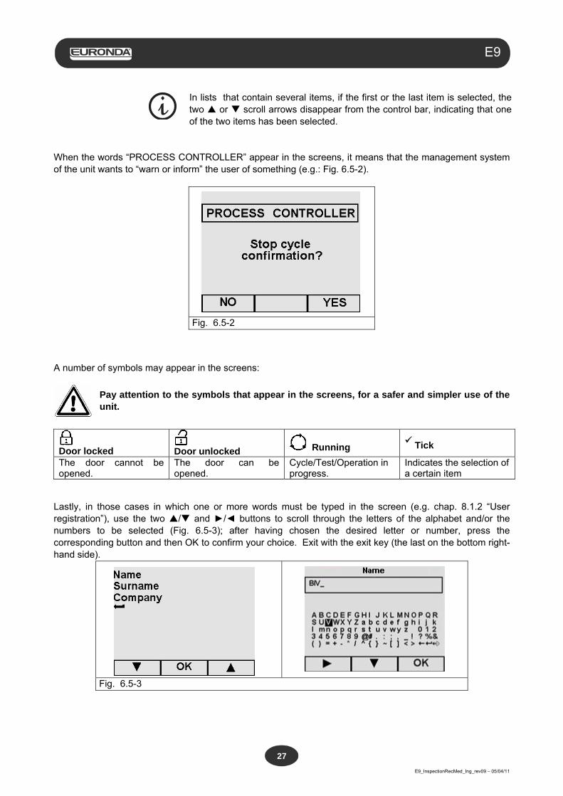
In lists that contain several items, if the first or the last item is selected, the two or scroll arrows disappear from the control bar, indicating that one of the two items has been selected.
When the words “PROCESS CONTROLLER” appear in the screens, it means that the management system of the unit wants to “warn or inform” the user of something (e.g.: Fig. 6.5-2).
Fig. 6.5-2 A number of symbols may appear in the screens:
Pay attention to the symbols that appear in the screens, for a safer and simpler use of the unit.
Door locked
Door unlocked Running
Tick
The door cannot be opened.
The door can be opened.
Cycle/Test/Operation in progress.
Indicates the selection of a certain item
Lastly, in those cases in which one or more words must be typed in the screen (e.g. chap. 8.1.2 “User registration”), use the two / and ►/◄ buttons to scroll through the letters of the alphabet and/or the numbers to be selected (Fig. 6.5-3); after having chosen the desired letter or number, press the corresponding button and then OK to confirm your choice. Exit with the exit key (the last on the bottom right-hand side).
Fig. 6.5-3
Aquafilter
E9_InspectionRecMed_Ing_rev09 – 05/04/11
28
E9
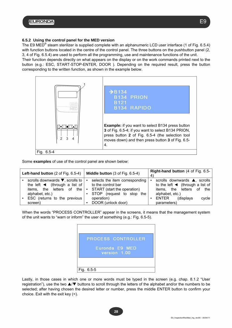
6.5.2 Using the control panel for the MED version The E9 MED® steam sterilizer is supplied complete with an alphanumeric LCD user interface (1 of Fig. 6.5.4) with function buttons located in the centre of the control panel. The three buttons on the pushbutton panel (2, 3, 4 of Fig. 6.5.4) are used to perform all the programming, use and maintenance functions of the unit. Their function depends directly on what appears on the display or on the work commands printed next to the button (e.g.: ESC, START-STOP-ENTER, DOOR ). Depending on the required result, press the button corresponding to the written function, as shown in the example below.
1
2 3 4
Example: if you want to select B134 press button 3 of Fig. 6.5-4; if you want to select B134 PRION, press button 2 of Fig. 6.5-4 (the selection tool moves down) and then press button 3 of Fig. 6.5-4.
Fig. 6.5-4 Some examples of use of the control panel are shown below:
Left-hand button (2 of Fig. 6.5-4) Middle button (3 of Fig. 6.5-4) Right-hand button (4 of Fig. 6.5-4)
▪ scrolls downwards , scrolls to the left ◄ (through a list of items, the letters of the alphabet, etc.)
▪ ESC (returns to the previous screen)
▪ selects the item corresponding to the control bar
▪ START (start the operation) ▪ STOP (request to stop the
operation) ▪ DOOR (unlock door)
▪ scrolls downwards , scrolls to the left ◄ (through a list of items, the letters of the alphabet, etc.)
▪ ENTER (displays cycle parameters)
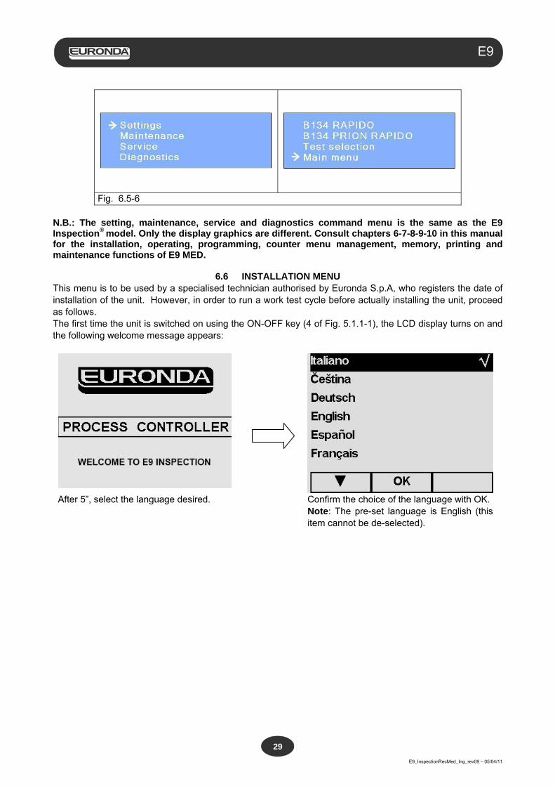
When the words “PROCESS CONTROLLER” appear in the screens, it means that the management system of the unit wants to “warn or inform” the user of something (e.g.: Fig. 6.5-5).
Fig. 6.5-5 Lastly, in those cases in which one or more words must be typed in the screen (e.g. chap. 8.1.2 “User registration”), use the two / buttons to scroll through the letters of the alphabet and/or the numbers to be selected; after having chosen the desired letter or number, press the middle ENTER button to confirm your choice. Exit with the exit key (<).
Aquafilter
E9_InspectionRecMed_Ing_rev09 – 05/04/11
29
E9
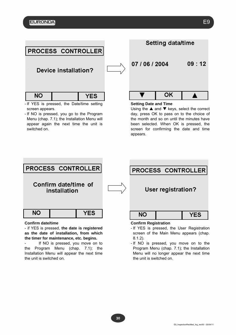
Fig. 6.5-6
N.B.: The setting, maintenance, service and diagnostics command menu is the same as the E9 Inspection® model. Only the display graphics are different. Consult chapters 6-7-8-9-10 in this manual for the installation, operating, programming, counter menu management, memory, printing and maintenance functions of E9 MED.
6.6 INSTALLATION MENU
This menu is to be used by a specialised technician authorised by Euronda S.p.A, who registers the date of installation of the unit. However, in order to run a work test cycle before actually installing the unit, proceed as follows. The first time the unit is switched on using the ON-OFF key (4 of Fig. 5.1.1-1), the LCD display turns on and the following welcome message appears:
After 5”, select the language desired.
Confirm the choice of the language with OK. Note: The pre-set language is English (this item cannot be de-selected).
Aquafilter
E9_InspectionRecMed_Ing_rev09 – 05/04/11
30
E9
- If YES is pressed, the Date/time setting
screen appears. - If NO is pressed, you go to the Program
Menu (chap. 7.1); the Installation Menu will appear again the next time the unit is switched on.
Setting Date and Time Using the and keys, select the correct day, press OK to pass on to the choice of the month and so on until the minutes have been selected. When OK is pressed, the screen for confirming the date and time appears.
Confirm date/time - if YES is pressed, the date is registered as the date of installation, from which the timer for maintenance, etc. begins. - If NO is pressed, you move on to the Program Menu (chap. 7.1); the Installation Menu will appear the next time the unit is switched on.
Confirm Registration - If YES is pressed, the User Registration
screen of the Main Menu appears (chap. 8.1.2).
- If NO is pressed, you move on to the Program Menu (chap. 7.1); the Installation Menu will no longer appear the next time the unit is switched on.
Aquafilter
E9_InspectionRecMed_Ing_rev09 – 05/04/11
31
E9
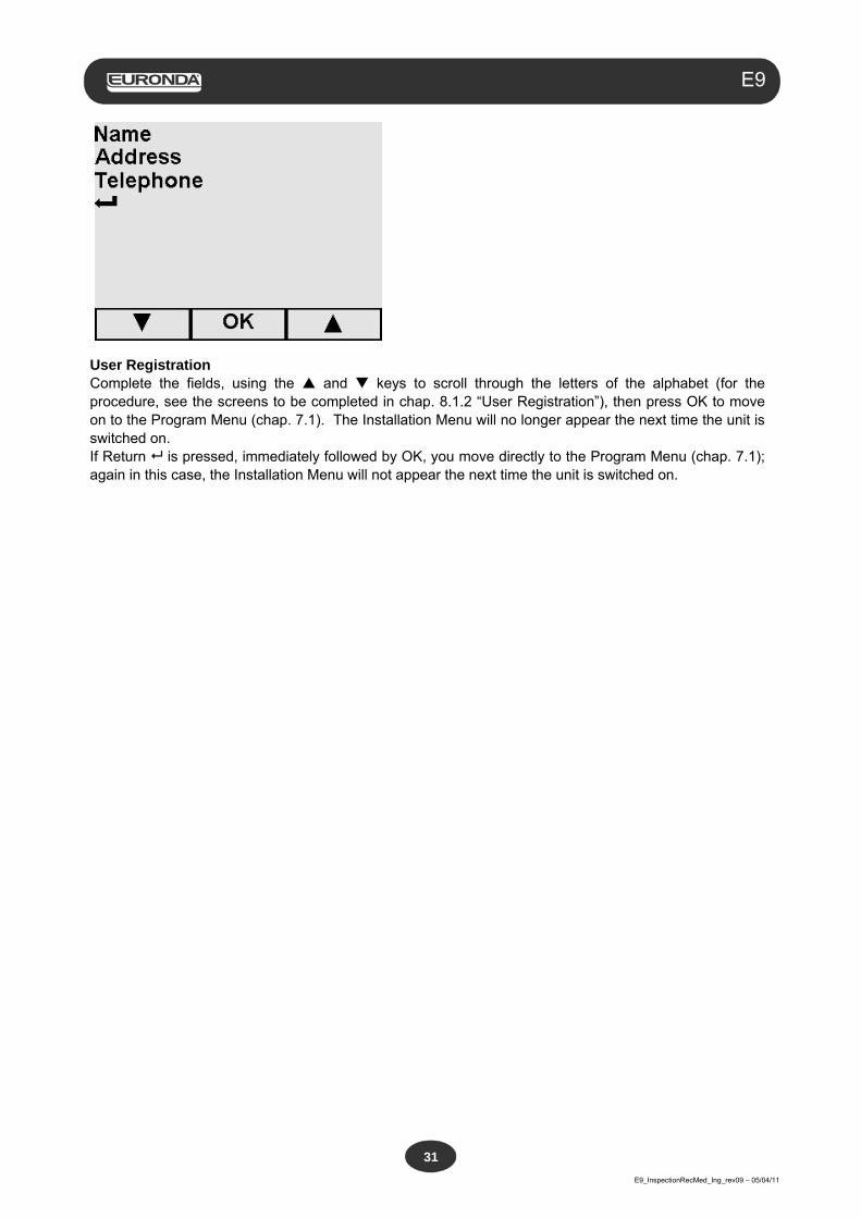
User Registration Complete the fields, using the and keys to scroll through the letters of the alphabet (for the procedure, see the screens to be completed in chap. 8.1.2 “User Registration”), then press OK to move on to the Program Menu (chap. 7.1). The Installation Menu will no longer appear the next time the unit is switched on. If Return is pressed, immediately followed by OK, you move directly to the Program Menu (chap. 7.1); again in this case, the Installation Menu will not appear the next time the unit is switched on.
Aquafilter
E9_InspectionRecMed_Ing_rev09 – 05/04/11
32
E9
6.7 TANKS: INSTRUCTIONS FOR FILLING AND DRAINING The unit features two separate tanks: one for the clean water required for the cycles, and one for the used water that is collected at the end of the cycles. Both tanks are connected with drain valves. Filling with distilled water for the first time
1. Switch on the unit with the ON-OFF button (4 of Fig. 5.1.1-1). The following message will appear on the display:
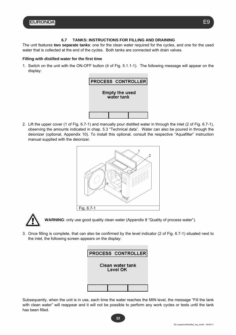
2. Lift the upper cover (1 of Fig. 6.7-1) and manually pour distilled water in through the inlet (2 of Fig. 6.7-1),
observing the amounts indicated in chap. 5.3 “Technical data”. Water can also be poured in through the deionizer (optional, Appendix 10). To install this optional, consult the respective “Aquafilter” instruction manual supplied with the deionizer.
21
Fig. 6.7-1
WARNING: only use good quality clean water (Appendix 8 “Quality of process water”).
3. Once filling is complete, that can also be confirmed by the level indicator (2 of Fig. 6.7-1) situated next to the inlet, the following screen appears on the display:
Subsequently, when the unit is in use, each time the water reaches the MIN level, the message “Fill the tank with clean water” will reappear and it will not be possible to perform any work cycles or tests until the tank has been filled.
Aquafilter
E9_InspectionRecMed_Ing_rev09 – 05/04/11
33
E9
Adding clean water
1. Empty the inner tank for collecting used water as described below in the par. “Emptying used water”.
2. Fill the clean water tank with fresh clean water, using the respective inlet (2 of Fig. 6.7-1).
WARNING: always use good quality clean water (Appendix 8 “Quality of process water”).
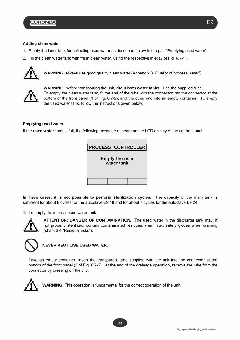
WARNING: before transporting the unit, drain both water tanks. Use the supplied tube. To empty the clean water tank, fit the end of the tube with the connector into the connector at the bottom of the front panel (1 of Fig. 6.7-2), and the other end into an empty container. To empty the used water tank, follow the instructions given below.
Emptying used water
If the used water tank is full, the following message appears on the LCD display of the control panel:
In these cases, it is not possible to perform sterilization cycles. The capacity of the main tank is sufficient for about 8 cycles for the autoclave E9 18 and for about 7 cycles for the autoclave E9 24. 1. To empty the internal used water tank:
ATTENTION: DANGER OF CONTAMINATION. The used water in the discharge tank may, if not properly sterilized, contain contaminated residues; wear latex safety gloves when draining (chap. 3.4 “Residual risks”).
NEVER REUTILISE USED WATER.
Take an empty container, insert the transparent tube supplied with the unit into the connector at the
bottom of the front panel (2 of Fig. 6.7-2). At the end of the drainage operation, remove the tube from the connector by pressing on the clip.
WARNING: This operation is fundamental for the correct operation of the unit.
Aquafilter
E9_InspectionRecMed_Ing_rev09 – 05/04/11
34
E9
12
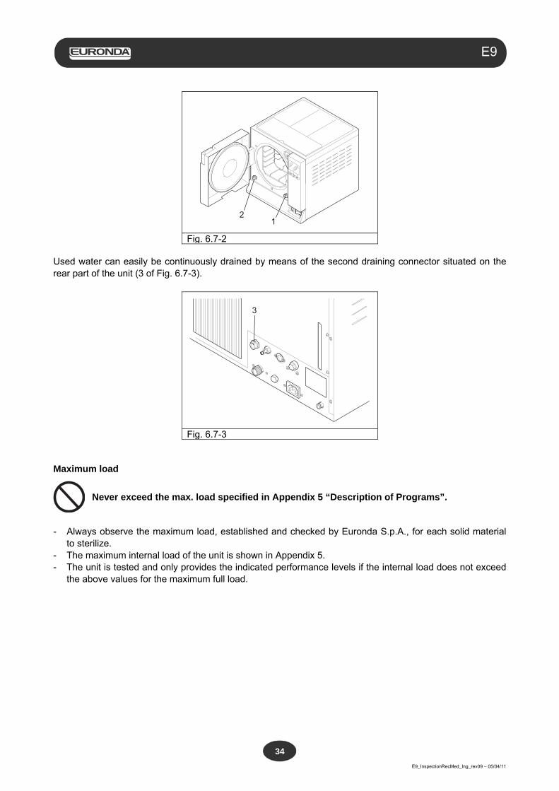
Fig. 6.7-2 Used water can easily be continuously drained by means of the second draining connector situated on the rear part of the unit (3 of Fig. 6.7-3).
3
Fig. 6.7-3 Maximum load
Never exceed the max. load specified in Appendix 5 “Description of Programs”.
- Always observe the maximum load, established and checked by Euronda S.p.A., for each solid material
to sterilize. - The maximum internal load of the unit is shown in Appendix 5. - The unit is tested and only provides the indicated performance levels if the internal load does not exceed
the above values for the maximum full load.
Aquafilter
E9_InspectionRecMed_Ing_rev09 – 05/04/11
35
E9
CHAPTER 7
7.1 PROGRAM MENU
Before beginning to operate the unit, carefully read all the warnings indicated in this manual, especially chap. 3 “Safety”.
NEVER LIFT the upper cover that covers the object-storage compartment and the water inlet during the sterilization cycle.
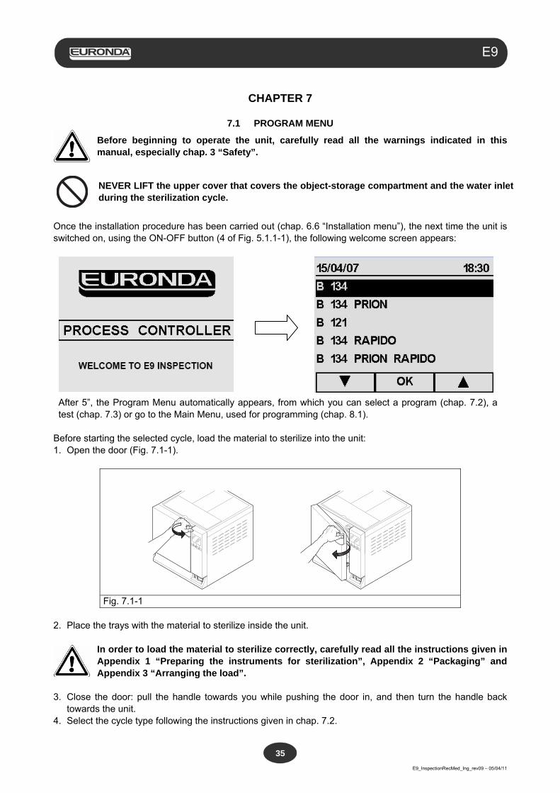
Once the installation procedure has been carried out (chap. 6.6 “Installation menu”), the next time the unit is switched on, using the ON-OFF button (4 of Fig. 5.1.1-1), the following welcome screen appears:
After 5”, the Program Menu automatically appears, from which you can select a program (chap. 7.2), a test (chap. 7.3) or go to the Main Menu, used for programming (chap. 8.1).
Before starting the selected cycle, load the material to sterilize into the unit: 1. Open the door (Fig. 7.1-1).
Fig. 7.1-1 2. Place the trays with the material to sterilize inside the unit.
In order to load the material to sterilize correctly, carefully read all the instructions given in Appendix 1 “Preparing the instruments for sterilization”, Appendix 2 “Packaging” and Appendix 3 “Arranging the load”.
3. Close the door: pull the handle towards you while pushing the door in, and then turn the handle back
towards the unit. 4. Select the cycle type following the instructions given in chap. 7.2.
Aquafilter
E9_InspectionRecMed_Ing_rev09 – 05/04/11
36
E9
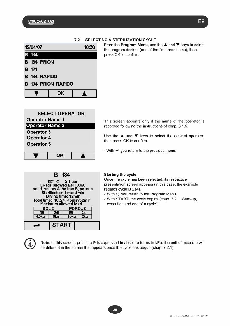
7.2 SELECTING A STERILIZATION CYCLE
From the Program Menu, use the and keys to select the program desired (one of the first three items), then press OK to confirm.
This screen appears only if the name of the operator is recorded following the instructions of chap. 8.1.5. Use the and keys to select the desired operator, then press OK to confirm. - With , you return to the previous menu.
Starting the cycle Once the cycle has been selected, its respective presentation screen appears (in this case, the example regards cycle B 134). - With , you return to the Program Menu. - With START, the cycle begins (chap. 7.2.1 “Start-up,
execution and end of a cycle”).
Note. In this screen, pressure P is expressed in absolute terms in kPa; the unit of measure will be different in the screen that appears once the cycle has begun (chap. 7.2.1).
Aquafilter
E9_InspectionRecMed_Ing_rev09 – 05/04/11
37
E9
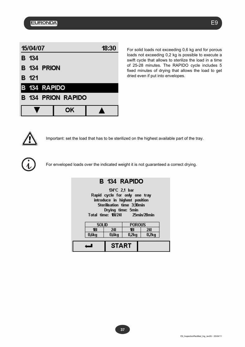
For solid loads not exceeding 0,6 kg and for porous
loads not exceeding 0,2 kg is possible to execute a swift cycle that allows to sterilize the load in a time of 25-28 minutes. The RAPIDO cycle includes 5 fixed minutes of drying that allows the load to get dried even if put into envelopes.
Important: set the load that has to be sterilized on the highest available part of the tray.
For enveloped loads over the indicated weight it is not guaranteed a correct drying.
Aquafilter
E9_InspectionRecMed_Ing_rev09 – 05/04/11
38
E9
7.2.1 Start-up, execution and end of a cycle
If the AFNOR block is enabled, the machine is programmed to perform cycle B 134 PRION. A password must be entered to perform the other cycles (see annex 11).
After pressing the START button to begin the selected cycle, the screen below appears that in this case, purely as an example, refers to cycle B 134, The same procedures and the same type of information indicated below also apply to the other two cycles B 134 PRION, B 121, B134 RAPIDO.
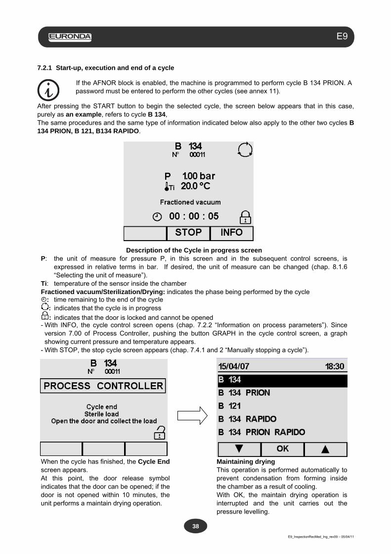
Description of the Cycle in progress screen P: the unit of measure for pressure P, in this screen and in the subsequent control screens, is
expressed in relative terms in bar. If desired, the unit of measure can be changed (chap. 8.1.6 “Selecting the unit of measure”).
Ti: temperature of the sensor inside the chamber Fractioned vacuum/Sterilization/Drying: indicates the phase being performed by the cycle : time remaining to the end of the cycle
: indicates that the cycle is in progress
: indicates that the door is locked and cannot be opened - With INFO, the cycle control screen opens (chap. 7.2.2 “Information on process parameters”). Since
version 7.00 of Process Controller, pushing the button GRAPH in the cycle control screen, a graph showing current pressure and temperature appears.
- With STOP, the stop cycle screen appears (chap. 7.4.1 and 2 “Manually stopping a cycle”).
When the cycle has finished, the Cycle End screen appears. At this point, the door release symbol indicates that the door can be opened; if the door is not opened within 10 minutes, the unit performs a maintain drying operation.
Maintaining drying This operation is performed automatically to prevent condensation from forming inside the chamber as a result of cooling. With OK, the maintain drying operation is interrupted and the unit carries out the pressure levelling.
Aquafilter
E9_InspectionRecMed_Ing_rev09 – 05/04/11
39
E9
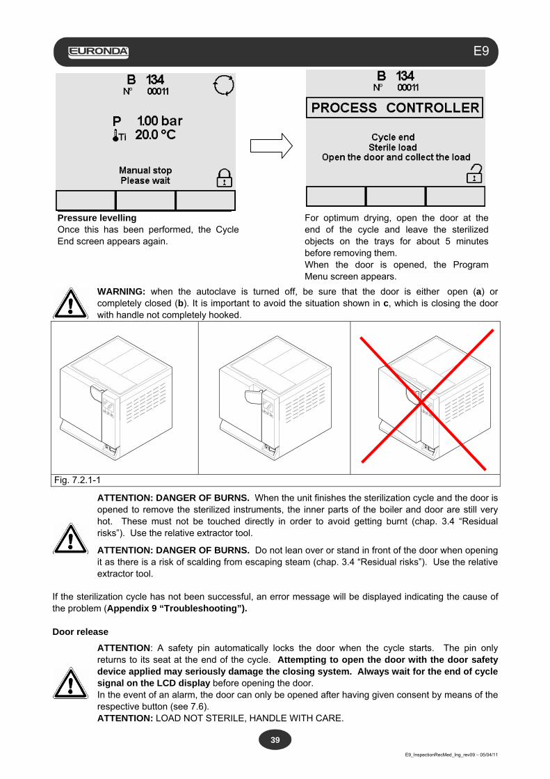
Pressure levelling Once this has been performed, the Cycle End screen appears again.
For optimum drying, open the door at the end of the cycle and leave the sterilized objects on the trays for about 5 minutes before removing them. When the door is opened, the Program Menu screen appears.
WARNING: when the autoclave is turned off, be sure that the door is either open (a) or completely closed (b). It is important to avoid the situation shown in c, which is closing the door with handle not completely hooked.
Fig. 7.2.1-1
ATTENTION: DANGER OF BURNS. When the unit finishes the sterilization cycle and the door is opened to remove the sterilized instruments, the inner parts of the boiler and door are still very hot. These must not be touched directly in order to avoid getting burnt (chap. 3.4 “Residual risks”). Use the relative extractor tool.
ATTENTION: DANGER OF BURNS. Do not lean over or stand in front of the door when opening it as there is a risk of scalding from escaping steam (chap. 3.4 “Residual risks”). Use the relative extractor tool.
If the sterilization cycle has not been successful, an error message will be displayed indicating the cause of the problem (Appendix 9 “Troubleshooting”). Door release
ATTENTION: A safety pin automatically locks the door when the cycle starts. The pin only returns to its seat at the end of the cycle. Attempting to open the door with the door safety device applied may seriously damage the closing system. Always wait for the end of cycle signal on the LCD display before opening the door. In the event of an alarm, the door can only be opened after having given consent by means of the respective button (see 7.6). ATTENTION: LOAD NOT STERILE, HANDLE WITH CARE.
Aquafilter
E9_InspectionRecMed_Ing_rev09 – 05/04/11
40
E9
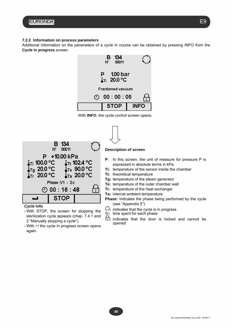
7.2.2 Information on process parameters Additional information on the parameters of a cycle in course can be obtained by pressing INFO from the Cycle in progress screen.
With INFO, the cycle control screen opens.
Cycle Info - With STOP, the screen for stopping the
sterilization cycle appears (chap. 7.4.1 and 2 “Manually stopping a cycle”).
- With , the cycle in progress screen opens again.
Description of screen P: In this screen, the unit of measure for pressure P is
expressed in absolute terms in kPa. Ti: temperature of the sensor inside the chamber Tt: theoretical temperature Tg: temperature of the steam generator Te: temperature of the outer chamber wall Tr: temperature of the heat exchanger Ta: internal ambient temperature Phase: indicates the phase being performed by the cycle
(see “Appendix 5”)
: indicates that the cycle is in progress : time spent for each phase
: indicates that the door is locked and cannot be opened
Aquafilter
E9_InspectionRecMed_Ing_rev09 – 05/04/11
41
E9
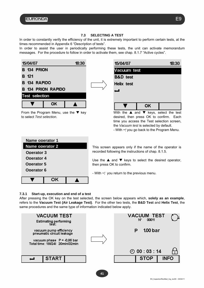
7.3 SELECTING A TEST
In order to constantly verify the efficiency of the unit, it is extremely important to perform certain tests, at the times recommended in Appendix 6 “Description of tests”. In order to assist the user in periodically performing these tests, the unit can activate memorandum messages. For the procedure to follow in order to activate them, see chap. 8.1.7 “Active cycles”.
From the Program Menu, use the key to select Test selection.
With the and keys, select the test desired, then press OK to confirm. Each time you access the Test selection screen, the Vacuum test is selected by default. - With , you go back to the Program Menu.
This screen appears only if the name of the operator is recorded following the instructions of chap. 8.1.5. Use the and keys to select the desired operator, then press OK to confirm. - With , you return to the previous menu.
7.3.1 Start-up, execution and end of a test After pressing the OK key on the test selected, the screen below appears which, solely as an example, refers to the Vacuum Test (Air Leakage Test). For the other two tests, the B&D Test and Helix Test, the same procedures and the same type of information indicated below apply.
Name operator 1
Name operator 2
Operator 3 Operator 4
Operator 5
Operator 6
Aquafilter
E9_InspectionRecMed_Ing_rev09 – 05/04/11
42
E9
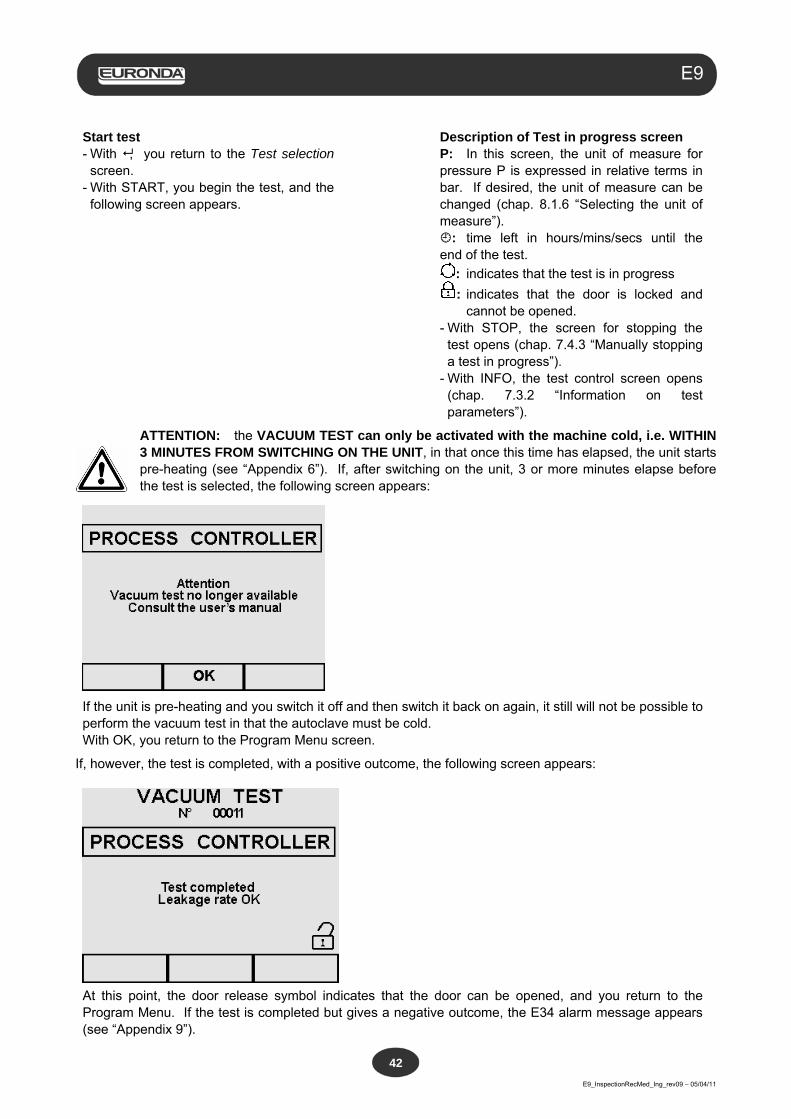
Start test - With , you return to the Test selection
screen. - With START, you begin the test, and the
following screen appears.
Description of Test in progress screen P: In this screen, the unit of measure for pressure P is expressed in relative terms in bar. If desired, the unit of measure can be changed (chap. 8.1.6 “Selecting the unit of measure”). : time left in hours/mins/secs until the end of the test.
: indicates that the test is in progress
: indicates that the door is locked and cannot be opened.
- With STOP, the screen for stopping the test opens (chap. 7.4.3 “Manually stopping a test in progress”).
- With INFO, the test control screen opens (chap. 7.3.2 “Information on test parameters”).
ATTENTION: the VACUUM TEST can only be activated with the machine cold, i.e. WITHIN 3 MINUTES FROM SWITCHING ON THE UNIT, in that once this time has elapsed, the unit starts pre-heating (see “Appendix 6”). If, after switching on the unit, 3 or more minutes elapse before the test is selected, the following screen appears:
If the unit is pre-heating and you switch it off and then switch it back on again, it still will not be possible to perform the vacuum test in that the autoclave must be cold. With OK, you return to the Program Menu screen.
If, however, the test is completed, with a positive outcome, the following screen appears:
At this point, the door release symbol indicates that the door can be opened, and you return to the Program Menu. If the test is completed but gives a negative outcome, the E34 alarm message appears (see “Appendix 9”).
Aquafilter
E9_InspectionRecMed_Ing_rev09 – 05/04/11
43
E9
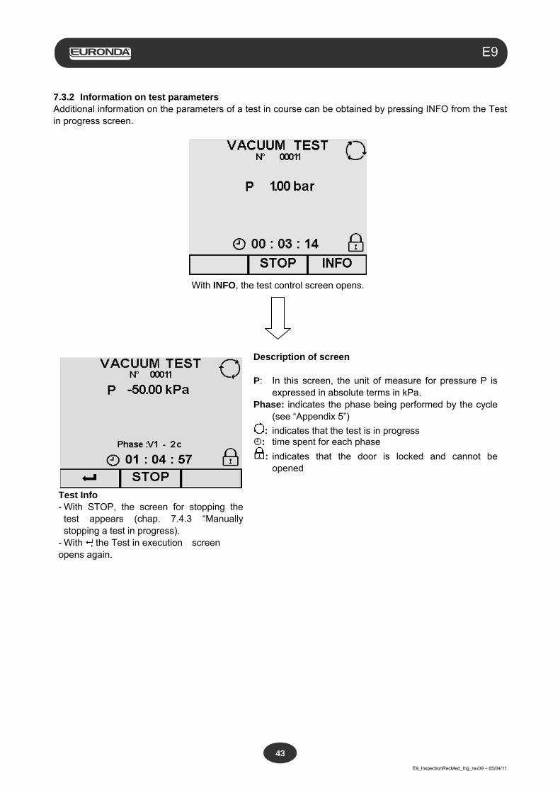
7.3.2 Information on test parameters Additional information on the parameters of a test in course can be obtained by pressing INFO from the Test in progress screen.
With INFO, the test control screen opens.
Test Info - With STOP, the screen for stopping the
test appears (chap. 7.4.3 “Manually stopping a test in progress).
- With , the Test in execution screen opens again.
Description of screen P: In this screen, the unit of measure for pressure P is
expressed in absolute terms in kPa. Phase: indicates the phase being performed by the cycle
(see “Appendix 5”)
: indicates that the test is in progress : time spent for each phase
: indicates that the door is locked and cannot be opened
Aquafilter
E9_InspectionRecMed_Ing_rev09 – 05/04/11
44
E9
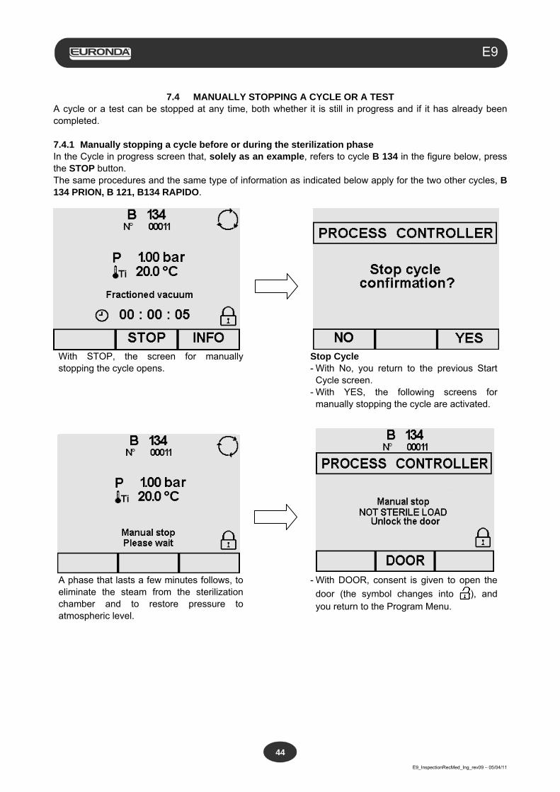
7.4 MANUALLY STOPPING A CYCLE OR A TEST
A cycle or a test can be stopped at any time, both whether it is still in progress and if it has already been completed. 7.4.1 Manually stopping a cycle before or during the sterilization phase In the Cycle in progress screen that, solely as an example, refers to cycle B 134 in the figure below, press the STOP button. The same procedures and the same type of information as indicated below apply for the two other cycles, B 134 PRION, B 121, B134 RAPIDO.
With STOP, the screen for manually stopping the cycle opens.
Stop Cycle - With No, you return to the previous Start
Cycle screen. - With YES, the following screens for
manually stopping the cycle are activated.
A phase that lasts a few minutes follows, to eliminate the steam from the sterilization chamber and to restore pressure to atmospheric level.
- With DOOR, consent is given to open the
door (the symbol changes into ), and you return to the Program Menu.
Aquafilter
E9_InspectionRecMed_Ing_rev09 – 05/04/11
45
E9
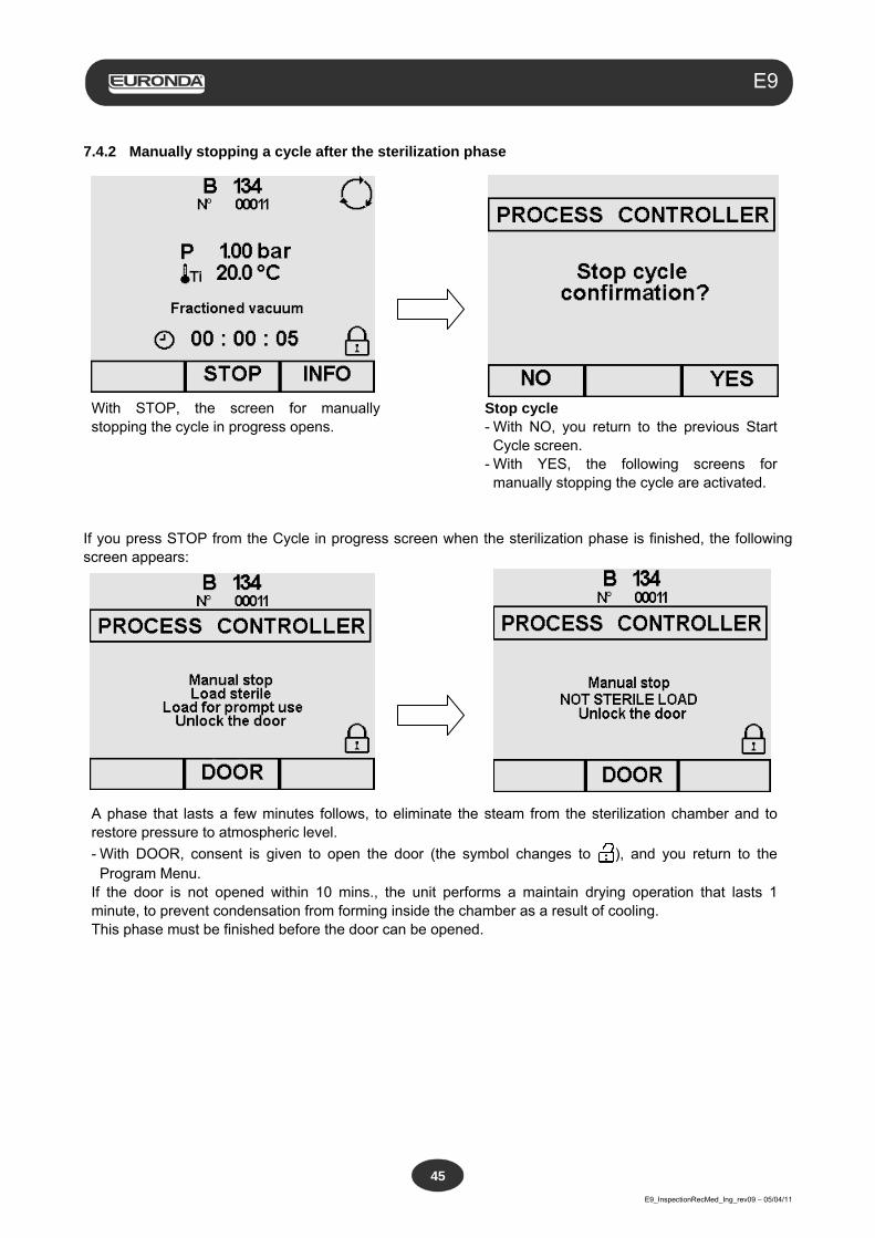
7.4.2 Manually stopping a cycle after the sterilization phase
With STOP, the screen for manually stopping the cycle in progress opens.
Stop cycle - With NO, you return to the previous Start
Cycle screen. - With YES, the following screens for
manually stopping the cycle are activated. If you press STOP from the Cycle in progress screen when the sterilization phase is finished, the following screen appears:
A phase that lasts a few minutes follows, to eliminate the steam from the sterilization chamber and to restore pressure to atmospheric level.
- With DOOR, consent is given to open the door (the symbol changes to ), and you return to the Program Menu.
If the door is not opened within 10 mins., the unit performs a maintain drying operation that lasts 1 minute, to prevent condensation from forming inside the chamber as a result of cooling. This phase must be finished before the door can be opened.
Aquafilter
E9_InspectionRecMed_Ing_rev09 – 05/04/11
46
E9
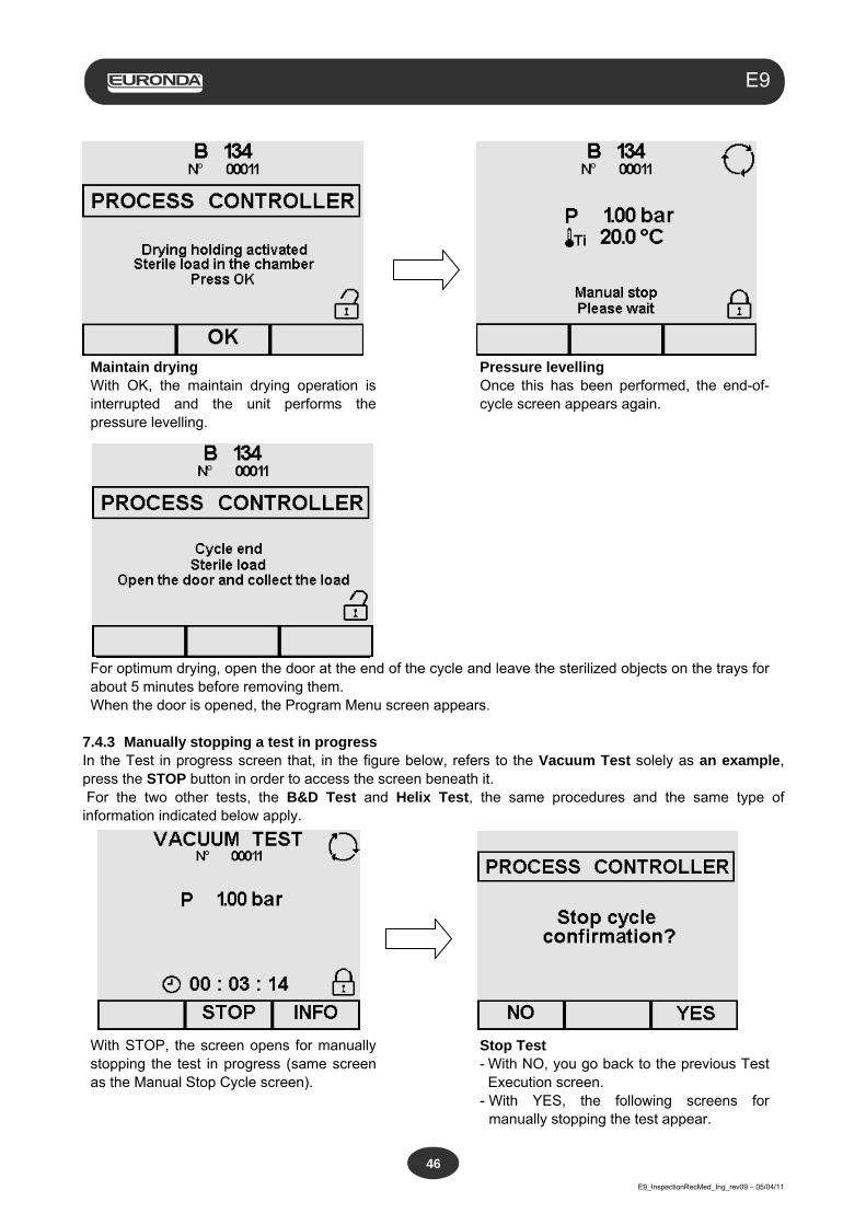
Maintain drying With OK, the maintain drying operation is interrupted and the unit performs the pressure levelling.
Pressure levelling Once this has been performed, the end-of-cycle screen appears again.
For optimum drying, open the door at the end of the cycle and leave the sterilized objects on the trays for about 5 minutes before removing them. When the door is opened, the Program Menu screen appears.
7.4.3 Manually stopping a test in progress In the Test in progress screen that, in the figure below, refers to the Vacuum Test solely as an example, press the STOP button in order to access the screen beneath it. For the two other tests, the B&D Test and Helix Test, the same procedures and the same type of information indicated below apply.
With STOP, the screen opens for manually stopping the test in progress (same screen as the Manual Stop Cycle screen).
Stop Test - With NO, you go back to the previous Test
Execution screen. - With YES, the following screens for
manually stopping the test appear.
Aquafilter
E9_InspectionRecMed_Ing_rev09 – 05/04/11
47
E9
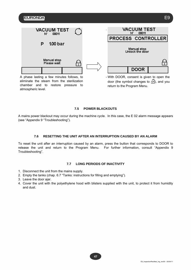
.
A phase lasting a few minutes follows, to eliminate the steam from the sterilization chamber and to restore pressure to atmospheric level.
- With DOOR, consent is given to open the
door (the symbol changes to ), and you return to the Program Menu.
7.5 POWER BLACKOUTS
A mains power blackout may occur during the machine cycle. In this case, the E 02 alarm message appears (see “Appendix 9 “Troubleshooting”).
7.6 RESETTING THE UNIT AFTER AN INTERRUPTION CAUSED BY AN ALARM
To reset the unit after an interruption caused by an alarm, press the button that corresponds to DOOR to release the unit and return to the Program Menu. For further information, consult “Appendix 9 Troubleshooting”.
7.7 LONG PERIODS OF INACTIVITY
1. Disconnect the unit from the mains supply. 2. Empty the tanks (chap. 6.7 “Tanks: instructions for filling and emptying”). 3. Leave the door ajar. 4. Cover the unit with the polyethylene hood with blisters supplied with the unit, to protect it from humidity
and dust.
Aquafilter
E9_InspectionRecMed_Ing_rev09 – 05/04/11
48
E9
CHAPTER 8
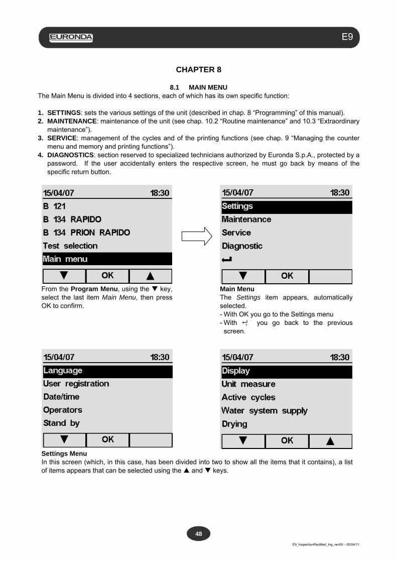
8.1 MAIN MENU The Main Menu is divided into 4 sections, each of which has its own specific function: 1. SETTINGS: sets the various settings of the unit (described in chap. 8 “Programming” of this manual). 2. MAINTENANCE: maintenance of the unit (see chap. 10.2 “Routine maintenance” and 10.3 “Extraordinary
maintenance”). 3. SERVICE: management of the cycles and of the printing functions (see chap. 9 “Managing the counter
menu and memory and printing functions”). 4. DIAGNOSTICS: section reserved to specialized technicians authorized by Euronda S.p.A., protected by a
password. If the user accidentally enters the respective screen, he must go back by means of the specific return button.
From the Program Menu, using the key, select the last item Main Menu, then press OK to confirm.
Main Menu The Settings item appears, automatically selected. - With OK you go to the Settings menu - With , you go back to the previous
screen.
Settings Menu In this screen (which, in this case, has been divided into two to show all the items that it contains), a list of items appears that can be selected using the and keys.
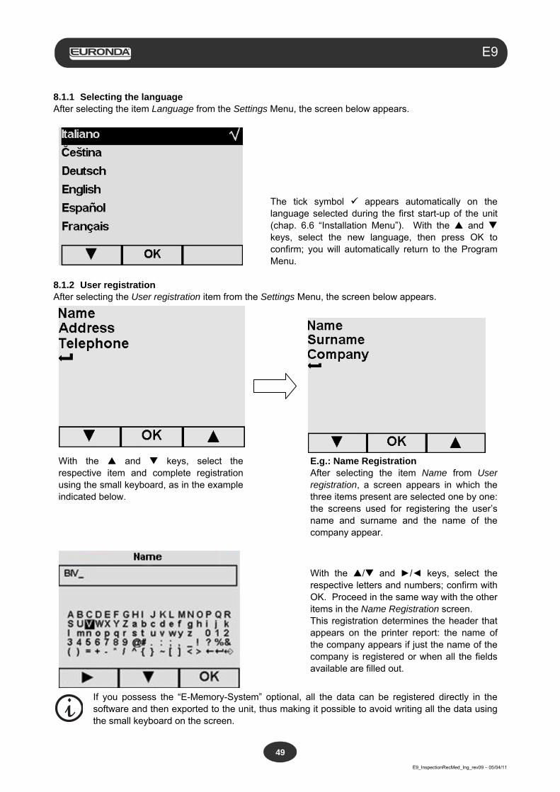
Aquafilter
E9_InspectionRecMed_Ing_rev09 – 05/04/11
49
E9
8.1.1 Selecting the language After selecting the item Language from the Settings Menu, the screen below appears.
The tick symbol appears automatically on the language selected during the first start-up of the unit (chap. 6.6 “Installation Menu”). With the and keys, select the new language, then press OK to confirm; you will automatically return to the Program Menu.
8.1.2 User registration After selecting the User registration item from the Settings Menu, the screen below appears.
With the and keys, select the respective item and complete registration using the small keyboard, as in the example indicated below.
E.g.: Name Registration After selecting the item Name from User registration, a screen appears in which the three items present are selected one by one: the screens used for registering the user’s name and surname and the name of the company appear.
With the / and ►/◄ keys, select the respective letters and numbers; confirm with OK. Proceed in the same way with the other items in the Name Registration screen. This registration determines the header that appears on the printer report: the name of the company appears if just the name of the company is registered or when all the fields available are filled out.
If you possess the “E-Memory-System” optional, all the data can be registered directly in the software and then exported to the unit, thus making it possible to avoid writing all the data using the small keyboard on the screen.
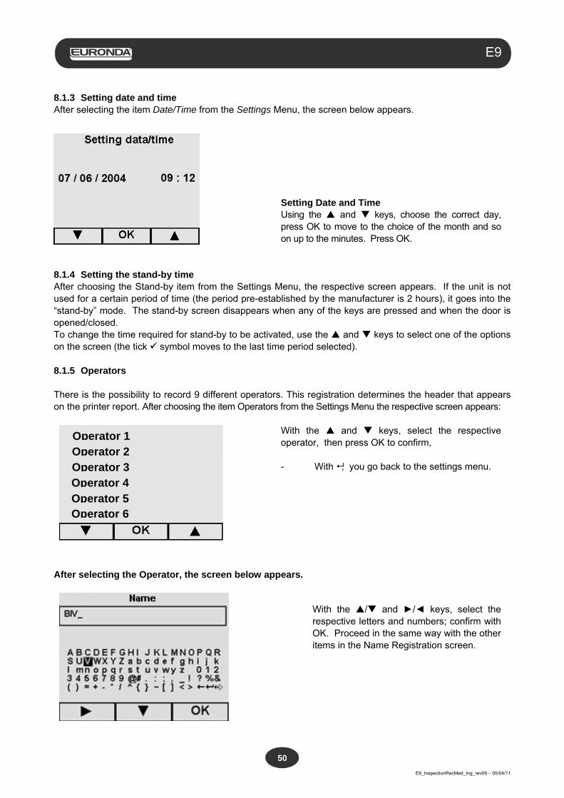
Aquafilter
E9_InspectionRecMed_Ing_rev09 – 05/04/11
50
E9
8.1.3 Setting date and time After selecting the item Date/Time from the Settings Menu, the screen below appears.
Setting Date and Time Using the and keys, choose the correct day, press OK to move to the choice of the month and so on up to the minutes. Press OK.
8.1.4 Setting the stand-by time After choosing the Stand-by item from the Settings Menu, the respective screen appears. If the unit is not used for a certain period of time (the period pre-established by the manufacturer is 2 hours), it goes into the “stand-by” mode. The stand-by screen disappears when any of the keys are pressed and when the door is opened/closed. To change the time required for stand-by to be activated, use the and keys to select one of the options on the screen (the tick symbol moves to the last time period selected). 8.1.5 Operators There is the possibility to record 9 different operators. This registration determines the header that appears on the printer report. After choosing the item Operators from the Settings Menu the respective screen appears:
With the and keys, select the respective operator, then press OK to confirm, - With , you go back to the settings menu.
After selecting the Operator, the screen below appears.
With the / and ►/◄ keys, select the respective letters and numbers; confirm with OK. Proceed in the same way with the other items in the Name Registration screen.
Operator 3 Operator 4 Operator 5 Operator 6
Operator 1 Operator 2
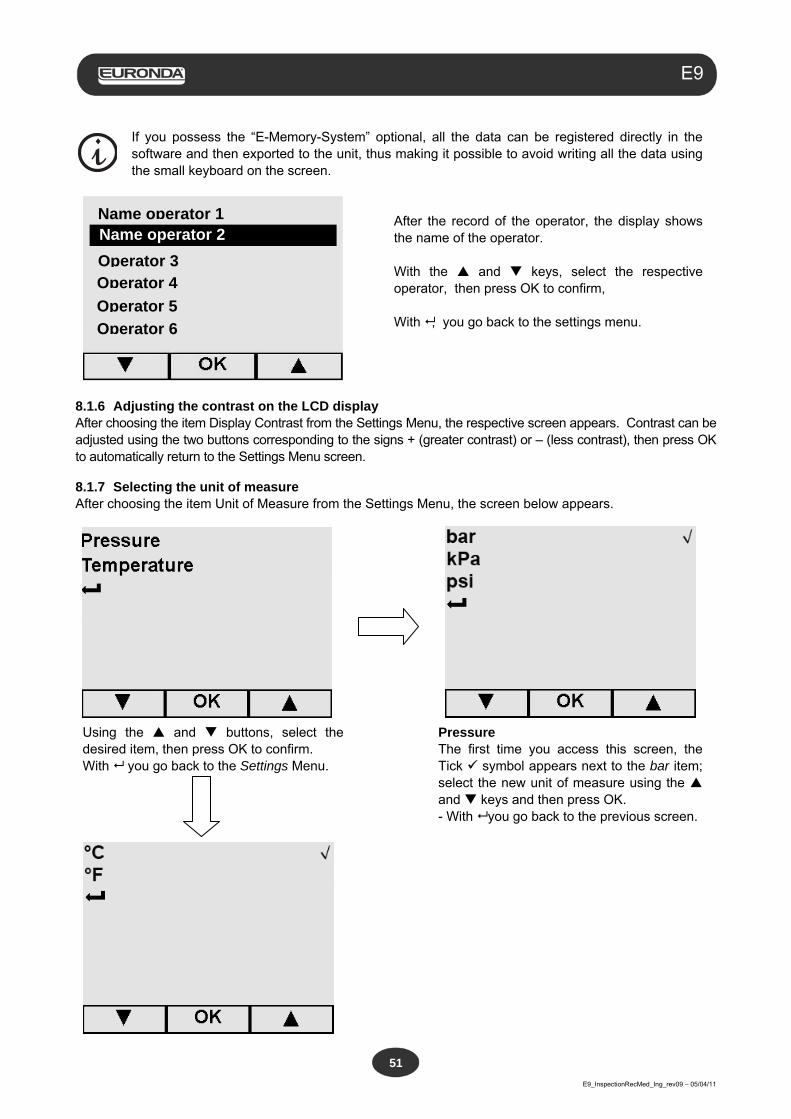
Aquafilter
E9_InspectionRecMed_Ing_rev09 – 05/04/11
51
E9
If you possess the “E-Memory-System” optional, all the data can be registered directly in the software and then exported to the unit, thus making it possible to avoid writing all the data using the small keyboard on the screen.
After the record of the operator, the display shows the name of the operator. With the and keys, select the respective operator, then press OK to confirm, With , you go back to the settings menu.
8.1.6 Adjusting the contrast on the LCD display After choosing the item Display Contrast from the Settings Menu, the respective screen appears. Contrast can be adjusted using the two buttons corresponding to the signs + (greater contrast) or – (less contrast), then press OK to automatically return to the Settings Menu screen.
8.1.7 Selecting the unit of measure After choosing the item Unit of Measure from the Settings Menu, the screen below appears.
Using the and buttons, select the desired item, then press OK to confirm. With you go back to the Settings Menu.
Pressure The first time you access this screen, the Tick symbol appears next to the bar item; select the new unit of measure using the and keys and then press OK. - With you go back to the previous screen.
Name operator 1 Name operator 2
Operator 3 Operator 4
Operator 5
Operator 6
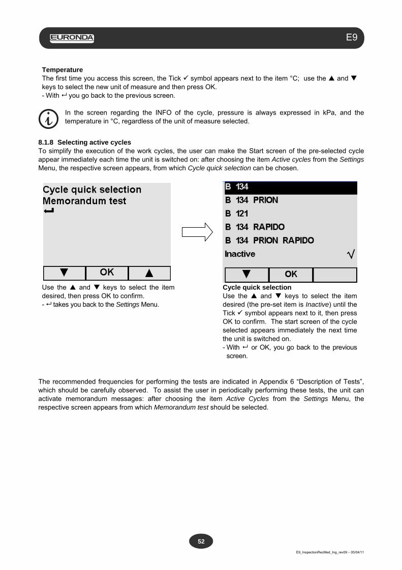
Aquafilter
E9_InspectionRecMed_Ing_rev09 – 05/04/11
52
E9
Temperature The first time you access this screen, the Tick symbol appears next to the item °C; use the and keys to select the new unit of measure and then press OK. - With you go back to the previous screen.
In the screen regarding the INFO of the cycle, pressure is always expressed in kPa, and the temperature in °C, regardless of the unit of measure selected.
8.1.8 Selecting active cycles To simplify the execution of the work cycles, the user can make the Start screen of the pre-selected cycle appear immediately each time the unit is switched on: after choosing the item Active cycles from the Settings Menu, the respective screen appears, from which Cycle quick selection can be chosen.
Use the and keys to select the item desired, then press OK to confirm. - takes you back to the Settings Menu.
Cycle quick selection Use the and keys to select the item desired (the pre-set item is Inactive) until the Tick symbol appears next to it, then press OK to confirm. The start screen of the cycle selected appears immediately the next time the unit is switched on. - With or OK, you go back to the previous
screen. The recommended frequencies for performing the tests are indicated in Appendix 6 “Description of Tests”, which should be carefully observed. To assist the user in periodically performing these tests, the unit can activate memorandum messages: after choosing the item Active Cycles from the Settings Menu, the respective screen appears from which Memorandum test should be selected.
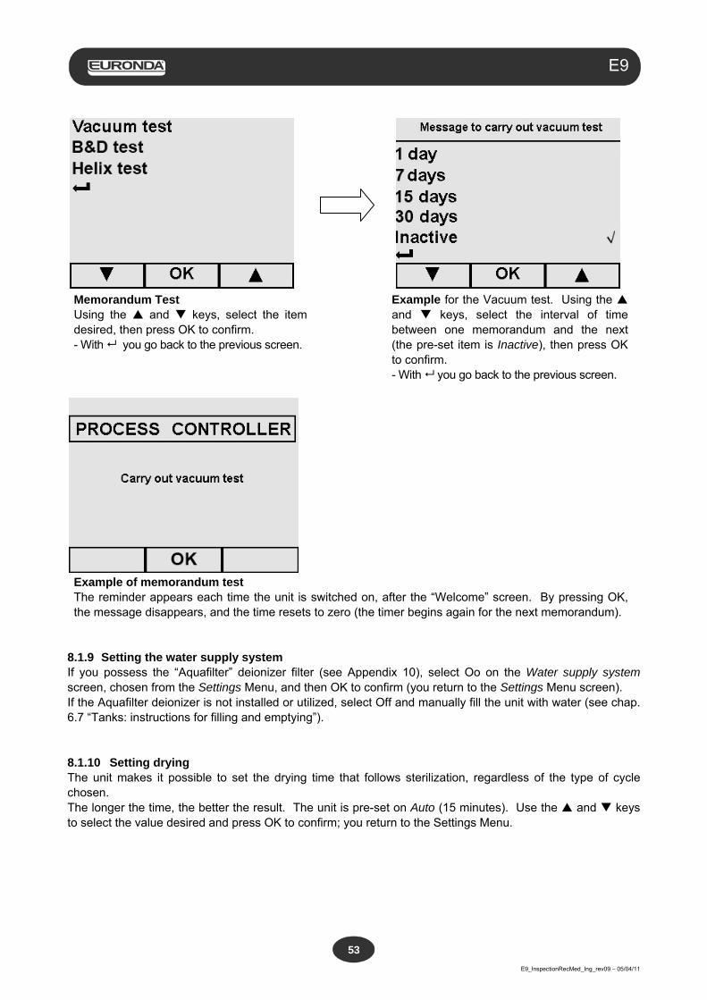
Aquafilter
E9_InspectionRecMed_Ing_rev09 – 05/04/11
53
E9
Memorandum Test Using the and keys, select the item desired, then press OK to confirm. - With you go back to the previous screen.
Example for the Vacuum test. Using the and keys, select the interval of time between one memorandum and the next (the pre-set item is Inactive), then press OK to confirm. - With you go back to the previous screen.
Example of memorandum test The reminder appears each time the unit is switched on, after the “Welcome” screen. By pressing OK, the message disappears, and the time resets to zero (the timer begins again for the next memorandum).
8.1.9 Setting the water supply system If you possess the “Aquafilter” deionizer filter (see Appendix 10), select Oo on the Water supply system screen, chosen from the Settings Menu, and then OK to confirm (you return to the Settings Menu screen). If the Aquafilter deionizer is not installed or utilized, select Off and manually fill the unit with water (see chap. 6.7 “Tanks: instructions for filling and emptying”). 8.1.10 Setting drying The unit makes it possible to set the drying time that follows sterilization, regardless of the type of cycle chosen. The longer the time, the better the result. The unit is pre-set on Auto (15 minutes). Use the and keys to select the value desired and press OK to confirm; you return to the Settings Menu.
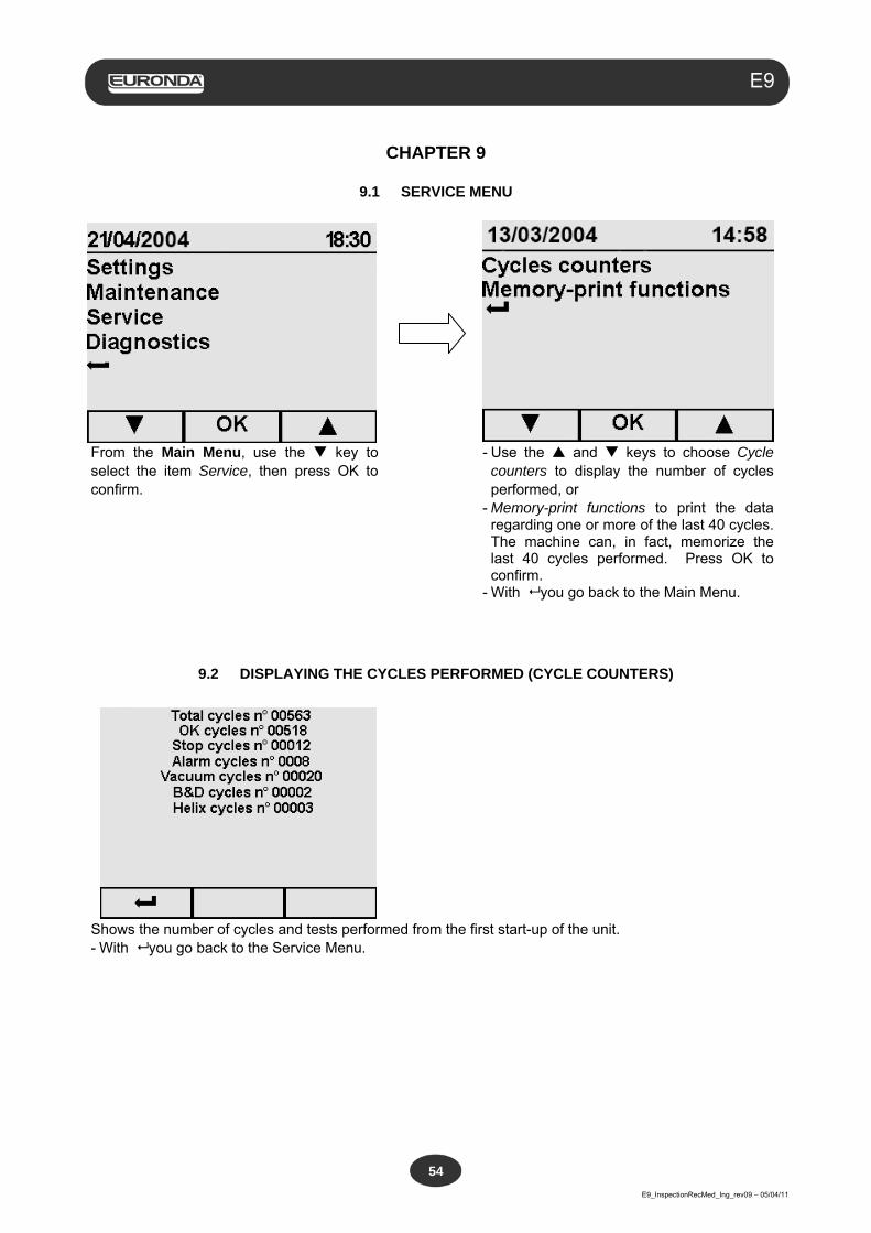
Aquafilter
E9_InspectionRecMed_Ing_rev09 – 05/04/11
54
E9
CHAPTER 9
9.1 SERVICE MENU
From the Main Menu, use the key to select the item Service, then press OK to confirm.
- Use the and keys to choose Cycle counters to display the number of cycles performed, or
- Memory-print functions to print the data regarding one or more of the last 40 cycles. The machine can, in fact, memorize the last 40 cycles performed. Press OK to confirm.
- With you go back to the Main Menu.
9.2 DISPLAYING THE CYCLES PERFORMED (CYCLE COUNTERS)
Shows the number of cycles and tests performed from the first start-up of the unit. - With you go back to the Service Menu.
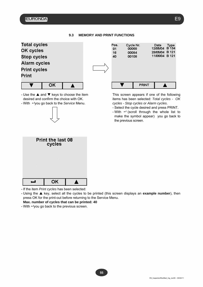
Aquafilter
E9_InspectionRecMed_Ing_rev09 – 05/04/11
55
E9
9.3 MEMORY AND PRINT FUNCTIONS
- Use the and keys to choose the item desired and confirm the choice with OK.
- With you go back to the Service Menu.
This screen appears if one of the following items has been selected: Total cycles - OK cycles - Stop cycles or Alarm cycles. - Select the cycle desired and press PRINT. - With (scroll through the whole list to
make the symbol appear) you go back to the previous screen.
- If the item Print cycles has been selected: - Using the key, select all the cycles to be printed (this screen displays an example number), then
press OK for the print-out before returning to the Service Menu. Max. number of cycles that can be printed: 40 - With you go back to the previous screen.
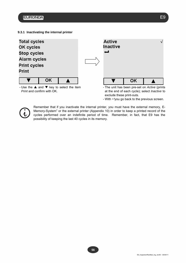
Aquafilter
E9_InspectionRecMed_Ing_rev09 – 05/04/11
56
E9
9.3.1 Inactivating the internal printer
- Use the and key to select the item Print and confirm with OK.
- The unit has been pre-set on Active (prints at the end of each cycle); select Inactive to exclude these print-outs.
- With you go back to the previous screen.
Remember that if you inactivate the internal printer, you must have the external memory, E-Memory-System” or the external printer (Appendix 10) in order to keep a printed record of the cycles performed over an indefinite period of time. Remember, in fact, that E9 has the possibility of keeping the last 40 cycles in its memory.
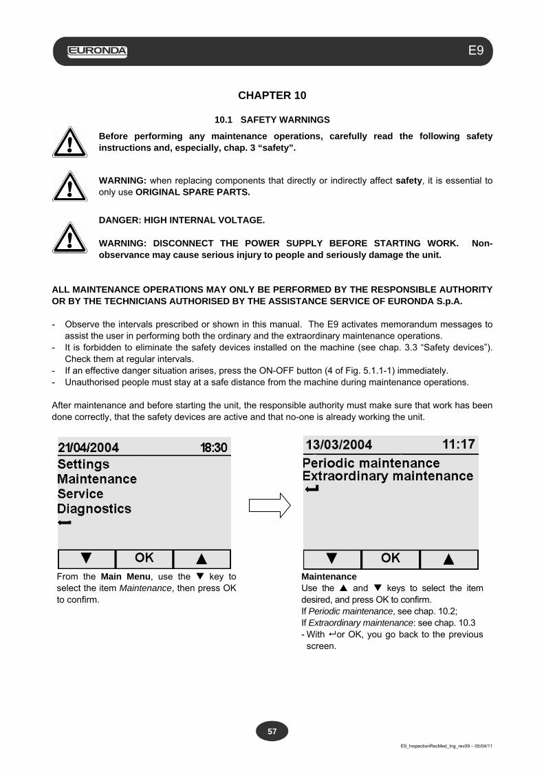
Aquafilter
E9_InspectionRecMed_Ing_rev09 – 05/04/11
57
E9
CHAPTER 10
10.1 SAFETY WARNINGS
Before performing any maintenance operations, carefully read the following safety instructions and, especially, chap. 3 “safety”.
WARNING: when replacing components that directly or indirectly affect safety, it is essential to only use ORIGINAL SPARE PARTS.
DANGER: HIGH INTERNAL VOLTAGE. WARNING: DISCONNECT THE POWER SUPPLY BEFORE STARTING WORK. Non-observance may cause serious injury to people and seriously damage the unit.
ALL MAINTENANCE OPERATIONS MAY ONLY BE PERFORMED BY THE RESPONSIBLE AUTHORITY OR BY THE TECHNICIANS AUTHORISED BY THE ASSISTANCE SERVICE OF EURONDA S.p.A. - Observe the intervals prescribed or shown in this manual. The E9 activates memorandum messages to
assist the user in performing both the ordinary and the extraordinary maintenance operations. - It is forbidden to eliminate the safety devices installed on the machine (see chap. 3.3 “Safety devices”).
Check them at regular intervals. - If an effective danger situation arises, press the ON-OFF button (4 of Fig. 5.1.1-1) immediately. - Unauthorised people must stay at a safe distance from the machine during maintenance operations. After maintenance and before starting the unit, the responsible authority must make sure that work has been done correctly, that the safety devices are active and that no-one is already working the unit.
From the Main Menu, use the key to select the item Maintenance, then press OK to confirm.
Maintenance Use the and keys to select the item desired, and press OK to confirm. If Periodic maintenance, see chap. 10.2; If Extraordinary maintenance: see chap. 10.3 - With or OK, you go back to the previous
screen.
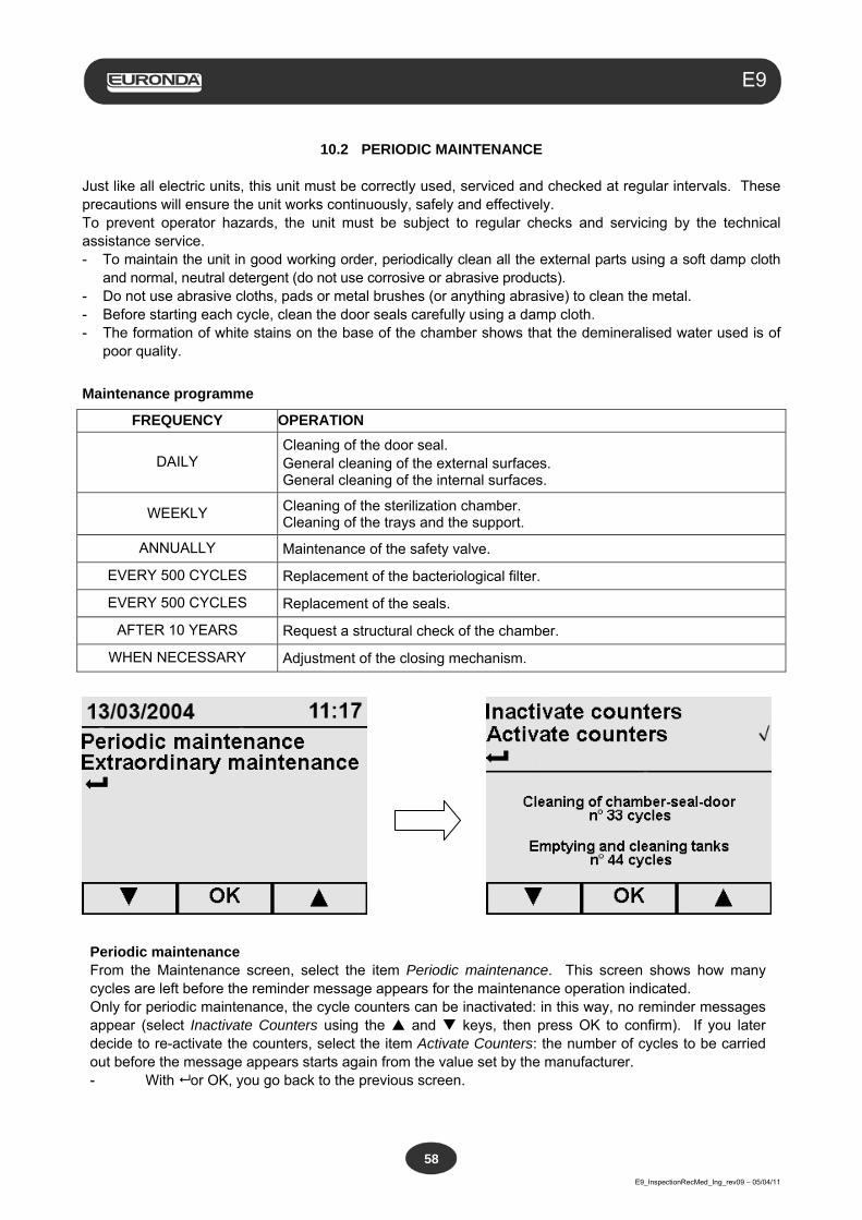
Aquafilter
E9_InspectionRecMed_Ing_rev09 – 05/04/11
58
E9
10.2 PERIODIC MAINTENANCE
Just like all electric units, this unit must be correctly used, serviced and checked at regular intervals. These precautions will ensure the unit works continuously, safely and effectively. To prevent operator hazards, the unit must be subject to regular checks and servicing by the technical assistance service. - To maintain the unit in good working order, periodically clean all the external parts using a soft damp cloth
and normal, neutral detergent (do not use corrosive or abrasive products). - Do not use abrasive cloths, pads or metal brushes (or anything abrasive) to clean the metal. - Before starting each cycle, clean the door seals carefully using a damp cloth. - The formation of white stains on the base of the chamber shows that the demineralised water used is of
poor quality.
Maintenance programme
FREQUENCY OPERATION
DAILY Cleaning of the door seal. General cleaning of the external surfaces. General cleaning of the internal surfaces.
WEEKLY Cleaning of the sterilization chamber. Cleaning of the trays and the support.
ANNUALLY Maintenance of the safety valve.
EVERY 500 CYCLES Replacement of the bacteriological filter.
EVERY 500 CYCLES Replacement of the seals.
AFTER 10 YEARS Request a structural check of the chamber.
WHEN NECESSARY Adjustment of the closing mechanism.
Periodic maintenance From the Maintenance screen, select the item Periodic maintenance. This screen shows how many cycles are left before the reminder message appears for the maintenance operation indicated. Only for periodic maintenance, the cycle counters can be inactivated: in this way, no reminder messages appear (select Inactivate Counters using the and keys, then press OK to confirm). If you later decide to re-activate the counters, select the item Activate Counters: the number of cycles to be carried out before the message appears starts again from the value set by the manufacturer. - With or OK, you go back to the previous screen.
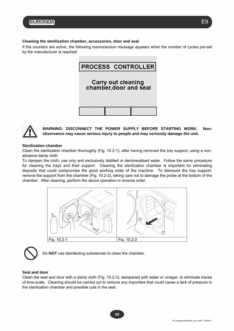
Aquafilter
E9_InspectionRecMed_Ing_rev09 – 05/04/11
59
E9
Cleaning the sterilization chamber, accessories, door and seal
If the counters are active, the following memorandum message appears when the number of cycles pre-set by the manufacturer is reached:
WARNING: DISCONNECT THE POWER SUPPLY BEFORE STARTING WORK. Non-observance may cause serious injury to people and may seriously damage the unit.
Sterilization chamber Clean the sterilization chamber thoroughly (Fig. 10.2-1), after having removed the tray support, using a non-abrasive damp cloth. To dampen the cloth, use only and exclusively distilled or demineralised water. Follow the same procedure for cleaning the trays and their support. Cleaning the sterilization chamber is important for eliminating deposits that could compromise the good working order of the machine. To dismount the tray support: remove the support from the chamber (Fig. 10.2-2), taking care not to damage the probe at the bottom of the chamber. After cleaning, perform the above operation in reverse order.
Do NOT use disinfecting substances to clean the chamber.
Seal and door Clean the seal and door with a damp cloth (Fig. 10.2-3), dampened with water or vinegar, to eliminate traces of lime-scale. Cleaning should be carried out to remove any impurities that could cause a lack of pressure in the sterilization chamber and possible cuts in the seal.
Fig. 10.2-1 Fig. 10.2-2
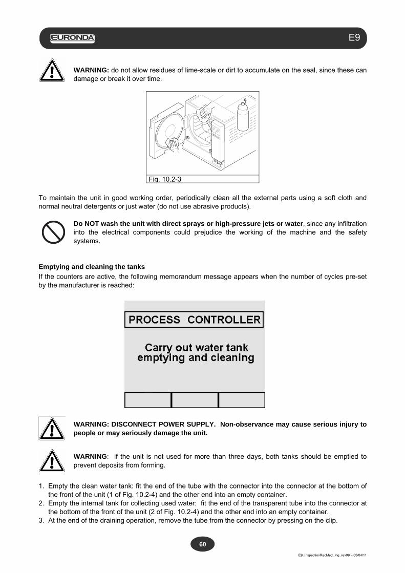
Aquafilter
E9_InspectionRecMed_Ing_rev09 – 05/04/11
60
E9
WARNING: do not allow residues of lime-scale or dirt to accumulate on the seal, since these can damage or break it over time.
To maintain the unit in good working order, periodically clean all the external parts using a soft cloth and normal neutral detergents or just water (do not use abrasive products).
Do NOT wash the unit with direct sprays or high-pressure jets or water, since any infiltration into the electrical components could prejudice the working of the machine and the safety systems.
Emptying and cleaning the tanks
If the counters are active, the following memorandum message appears when the number of cycles pre-set by the manufacturer is reached:
WARNING: DISCONNECT POWER SUPPLY. Non-observance may cause serious injury to people or may seriously damage the unit.
WARNING: if the unit is not used for more than three days, both tanks should be emptied to prevent deposits from forming.
1. Empty the clean water tank: fit the end of the tube with the connector into the connector at the bottom of
the front of the unit (1 of Fig. 10.2-4) and the other end into an empty container. 2. Empty the internal tank for collecting used water: fit the end of the transparent tube into the connector at
the bottom of the front of the unit (2 of Fig. 10.2-4) and the other end into an empty container. 3. At the end of the draining operation, remove the tube from the connector by pressing on the clip.
Fig. 10.2-3
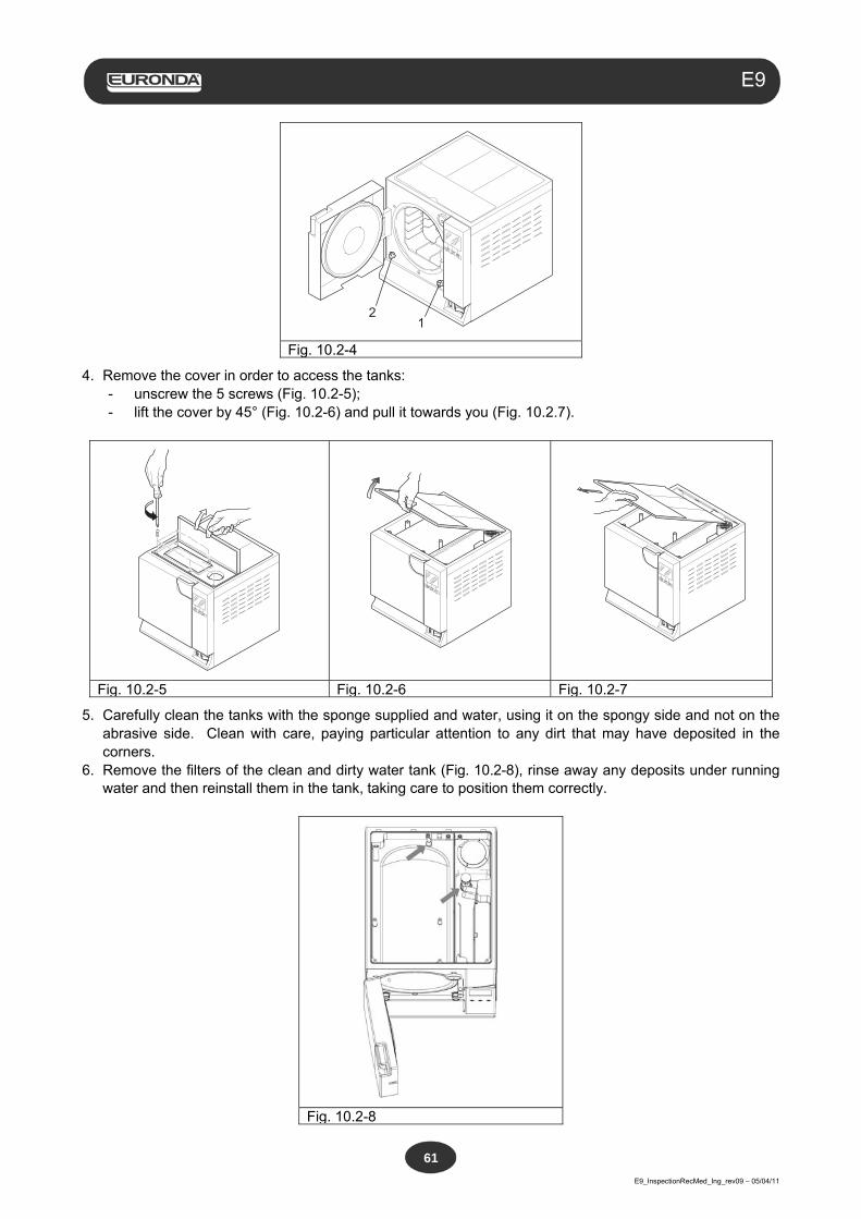
Aquafilter
E9_InspectionRecMed_Ing_rev09 – 05/04/11
61
E9
12
Fig. 10.2-4
4. Remove the cover in order to access the tanks: - unscrew the 5 screws (Fig. 10.2-5); - lift the cover by 45° (Fig. 10.2-6) and pull it towards you (Fig. 10.2.7).
Fig. 10.2-5 Fig. 10.2-6 Fig. 10.2-7
5. Carefully clean the tanks with the sponge supplied and water, using it on the spongy side and not on the abrasive side. Clean with care, paying particular attention to any dirt that may have deposited in the corners.
6. Remove the filters of the clean and dirty water tank (Fig. 10.2-8), rinse away any deposits under running water and then reinstall them in the tank, taking care to position them correctly.
Fig. 10.2-8
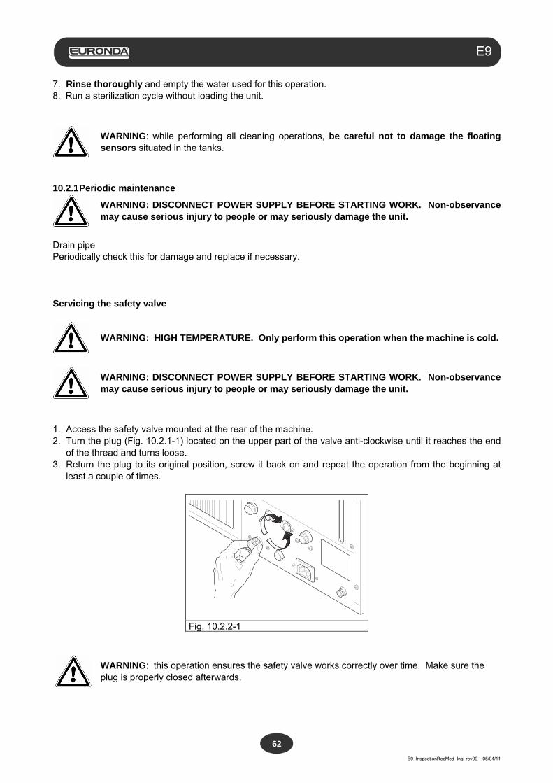
Aquafilter
E9_InspectionRecMed_Ing_rev09 – 05/04/11
62
E9
7. Rinse thoroughly and empty the water used for this operation. 8. Run a sterilization cycle without loading the unit.
WARNING: while performing all cleaning operations, be careful not to damage the floating sensors situated in the tanks.
10.2.1 Periodic maintenance
WARNING: DISCONNECT POWER SUPPLY BEFORE STARTING WORK. Non-observance may cause serious injury to people or may seriously damage the unit.
Drain pipe Periodically check this for damage and replace if necessary. Servicing the safety valve
WARNING: HIGH TEMPERATURE. Only perform this operation when the machine is cold.
WARNING: DISCONNECT POWER SUPPLY BEFORE STARTING WORK. Non-observance may cause serious injury to people or may seriously damage the unit.
1. Access the safety valve mounted at the rear of the machine. 2. Turn the plug (Fig. 10.2.1-1) located on the upper part of the valve anti-clockwise until it reaches the end
of the thread and turns loose. 3. Return the plug to its original position, screw it back on and repeat the operation from the beginning at
least a couple of times.
Fig. 10.2.2-1
WARNING: this operation ensures the safety valve works correctly over time. Make sure the plug is properly closed afterwards.
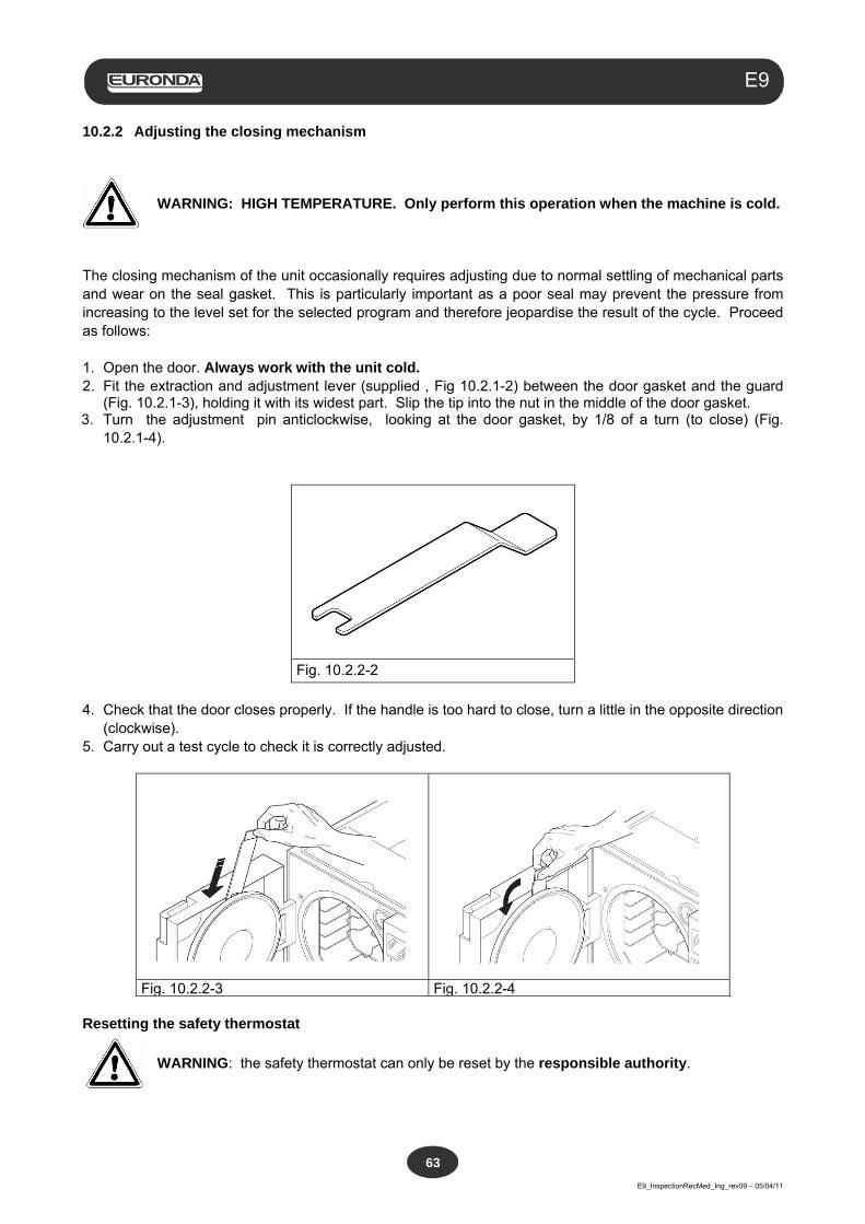
Aquafilter
E9_InspectionRecMed_Ing_rev09 – 05/04/11
63
E9
10.2.2 Adjusting the closing mechanism
WARNING: HIGH TEMPERATURE. Only perform this operation when the machine is cold.
The closing mechanism of the unit occasionally requires adjusting due to normal settling of mechanical parts and wear on the seal gasket. This is particularly important as a poor seal may prevent the pressure from increasing to the level set for the selected program and therefore jeopardise the result of the cycle. Proceed as follows: 1. Open the door. Always work with the unit cold. 2. Fit the extraction and adjustment lever (supplied , Fig 10.2.1-2) between the door gasket and the guard
(Fig. 10.2.1-3), holding it with its widest part. Slip the tip into the nut in the middle of the door gasket. 3. Turn the adjustment pin anticlockwise, looking at the door gasket, by 1/8 of a turn (to close) (Fig.
10.2.1-4).
Fig. 10.2.2-2
4. Check that the door closes properly. If the handle is too hard to close, turn a little in the opposite direction
(clockwise). 5. Carry out a test cycle to check it is correctly adjusted.
Fig. 10.2.2-3 Fig. 10.2.2-4
Resetting the safety thermostat
WARNING: the safety thermostat can only be reset by the responsible authority.
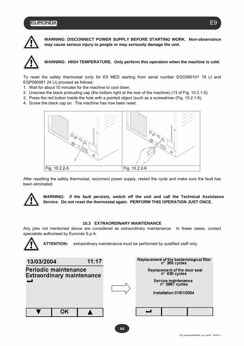
Aquafilter
E9_InspectionRecMed_Ing_rev09 – 05/04/11
64
E9
WARNING: DISCONNECT POWER SUPPLY BEFORE STARTING WORK. Non-observance may cause serious injury to people or may seriously damage the unit.
WARNING: HIGH TEMPERATURE. Only perform this operation when the machine is cold.
To reset the safety thermostat (only for E9 MED starting from serial number EGO090101 18 Lt and EGP090081 24 Lt) proceed as follows: 1. Wait for about 10 minutes for the machine to cool down. 2. Unscrew the black protruding cap (the bottom right at the rear of the machine) (13 of Fig. 10.2.1-5). 3. Press the red button inside the hole with a pointed object (such as a screwdriver (Fig. 10.2.1-6). 4. Screw the black cap on. The machine has now been reset.
1
Fig. 10.2.2-5 Fig. 10.2.2-6 After resetting the safety thermostat, reconnect power supply, restart the cycle and make sure the fault has been eliminated.
WARNING: if the fault persists, switch off the unit and call the Technical Assistance Service. Do not reset the thermostat again. PERFORM THIS OPERATION JUST ONCE.
10.3 EXTRAORDINARY MAINTENANCE Any jobs not mentioned above are considered as extraordinary maintenance. In these cases, contact specialists authorised by Euronda S.p.A.
ATTENTION: extraordinary maintenance must be performed by qualified staff only.
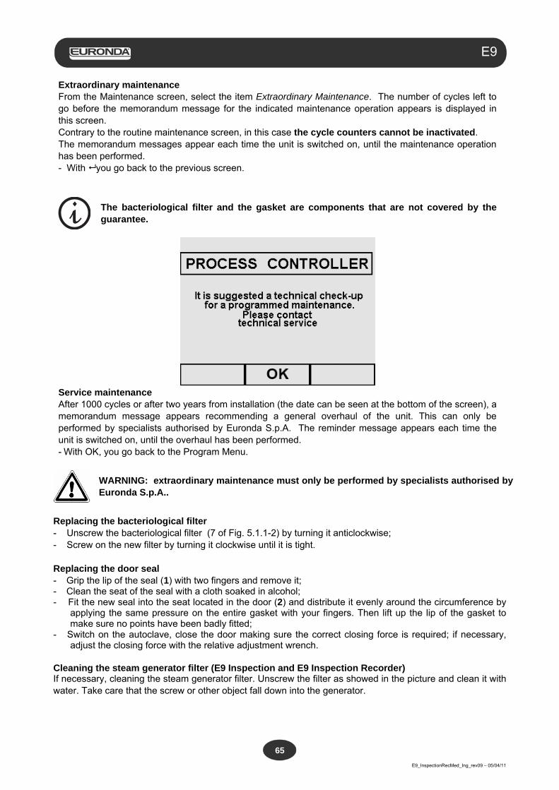
Aquafilter
E9_InspectionRecMed_Ing_rev09 – 05/04/11
65
E9
Extraordinary maintenance From the Maintenance screen, select the item Extraordinary Maintenance. The number of cycles left to go before the memorandum message for the indicated maintenance operation appears is displayed in this screen. Contrary to the routine maintenance screen, in this case the cycle counters cannot be inactivated. The memorandum messages appear each time the unit is switched on, until the maintenance operation has been performed. - With you go back to the previous screen.
The bacteriological filter and the gasket are components that are not covered by the guarantee.
Service maintenance After 1000 cycles or after two years from installation (the date can be seen at the bottom of the screen), a memorandum message appears recommending a general overhaul of the unit. This can only be performed by specialists authorised by Euronda S.p.A. The reminder message appears each time the unit is switched on, until the overhaul has been performed. - With OK, you go back to the Program Menu.
WARNING: extraordinary maintenance must only be performed by specialists authorised by Euronda S.p.A..
Replacing the bacteriological filter - Unscrew the bacteriological filter (7 of Fig. 5.1.1-2) by turning it anticlockwise; - Screw on the new filter by turning it clockwise until it is tight. Replacing the door seal - Grip the lip of the seal (1) with two fingers and remove it; - Clean the seat of the seal with a cloth soaked in alcohol; - Fit the new seal into the seat located in the door (2) and distribute it evenly around the circumference by
applying the same pressure on the entire gasket with your fingers. Then lift up the lip of the gasket to make sure no points have been badly fitted;
- Switch on the autoclave, close the door making sure the correct closing force is required; if necessary, adjust the closing force with the relative adjustment wrench.
Cleaning the steam generator filter (E9 Inspection and E9 Inspection Recorder) If necessary, cleaning the steam generator filter. Unscrew the filter as showed in the picture and clean it with water. Take care that the screw or other object fall down into the generator.
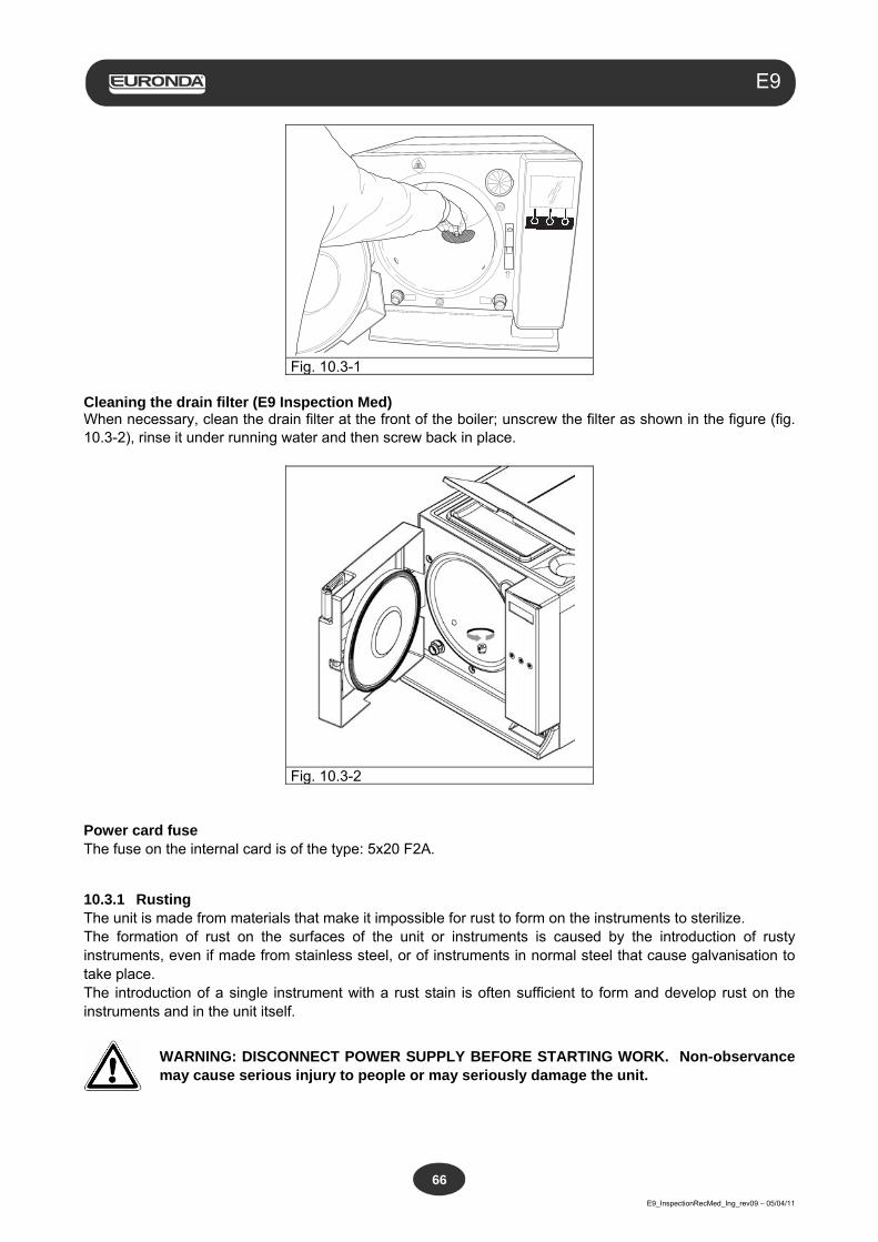
Aquafilter
E9_InspectionRecMed_Ing_rev09 – 05/04/11
66
E9
Fig. 10.3-1 Cleaning the drain filter (E9 Inspection Med) When necessary, clean the drain filter at the front of the boiler; unscrew the filter as shown in the figure (fig. 10.3-2), rinse it under running water and then screw back in place.
Fig. 10.3-2 Power card fuse The fuse on the internal card is of the type: 5x20 F2A.
10.3.1 Rusting The unit is made from materials that make it impossible for rust to form on the instruments to sterilize. The formation of rust on the surfaces of the unit or instruments is caused by the introduction of rusty instruments, even if made from stainless steel, or of instruments in normal steel that cause galvanisation to take place. The introduction of a single instrument with a rust stain is often sufficient to form and develop rust on the instruments and in the unit itself.
WARNING: DISCONNECT POWER SUPPLY BEFORE STARTING WORK. Non-observance may cause serious injury to people or may seriously damage the unit.

Aquafilter
E9_InspectionRecMed_Ing_rev09 – 05/04/11
67
E9
If rust forms in the unit, clean the walls of the sterilization chamber and the tray holder using special products for stainless steel, as described previously in the paragraph “Cleaning the sterilization chamber, accessories, door and gasket”.
WARNING: do not use metal sponges or brushes. Use a damp soft cloth to remove dirt stains.
Aquafilter
E9_InspectionRecMed_Ing_rev09 – 05/04/11
68
E9
CHAPTER 11
11.1 SCRAPPING INSTRUCTIONS The E9 unit has been manufactured using ferrous materials, electrical components and plastics. To scrap the unit, separate the various components according to the material they are made of in order to simplify reuse or differentiated disposal. No particular operations are required after scrapping. Do not dump the unit. Take it to a disposal company. Always refer to the specific laws in the country of use when scrapping and disposing of the appliance.
The symbol on the appliance means that it must be disposed of as “sorted waste”. The user must therefore send (or instruct other people to send) the unit to one of the sorted waste collection centres set up by the local councils, or send it to the dealer against the purchase of an equivalent unit (European Union only). Sorted waste collection and the subsequent treatment, recovery and disposal operations facilitate the production of equipment using recycled materials and limit the negative environmental and health effects that may be caused by improper waste management. Abusive dumping by the user will be punished according to law.
11.2 RESALE
If the unit is sold, hand over all the technical documentation to the new purchaser, inform him/her about any repair work carried out and how to use and service the machine. Also inform Euronda S.p.A. of the sale and provide it with data about the new purchaser.
Aquafilter
E9_InspectionRecMed_Ing_rev09 – 05/04/11
69
E9
APPENDIX 1 Preparing the instruments for sterilization
A correct sterilization depends on the processes described below being carried out correctly; these are all equally important and, therefore, care must be taken while performing them. 1. Preparing the instruments to sterilize 2. Packing 3. Loading 4. Sterilization 5. Preserving the sterilized instruments 6. Routine maintenance of the unit All the objects must be decontaminated and carefully cleaned and dried before being sterilized. In the case of instruments with parts that are joined to each other, divide the parts or open them as wide apart as possible. In the case of overalls or other reusable fabrics, these must be washed and dried after use and before sterilization, to remove organic material and lengthen the “life” of the fabric, restoring it with its natural water content (i.e. degree of humidity). The objectives of the initial decontamination procedure are as follows: a) inactivating bacterial proliferation b) preventing mutual contamination while handling instruments c) preventing any products on the instrument from drying d) protecting personnel Decontamination is carried out using detergents and, generally, solutions that are active against HIV, HBV and HCV, or by washing at 93°C for ten minutes in thermo-disinfectors. Observe the indications given in the technical data sheets of the products used. The instruments are cleaned so as to eliminate blood, saliva, dentin and organic substances in general, that may damage the materials to be sterilized or even the sterilizer itself. The use of ultrasound baths is recommended, which offer numerous advantages with respect to traditional cleaning methods, such as efficacy, speed and delicacy on the object being cleaned; always follow the recommendations provided by the respective manufacturers. In general, after ultrasound cleaning with detergent and/or disinfectant, rinsing the instrument is recommended, in that the disinfectant may take on corrosive characteristics as a result of the heat. Always clean the solution carefully to avoid residues of moisture. Once dry, the instruments to be sterilized in the unit must be appropriately packaged, whereas those to be cold sterilized must be immersed in the appropriate chemical solution (glutaraldehyde, paracetic acid, etc.). Checking the instruments to be used is also important: ensure that devices with the following characteristics are not subject to sterilization: - breaks - stains - rust - mono-use devices that cannot be reused
Aquafilter
E9_InspectionRecMed_Ing_rev09 – 05/04/11
70
E9
APPENDIX 2 Packaging
The correct packaging of the materials is essential in ensuring that sterility is maintained. Packaging of the instruments is done so as to maintain the materials sterile until the time of their use. The way in which the sterilized instruments are packaged, and then stocked, determines the state of preservation of sterilization. The following can be used as containers: metal containers with lids or perforated bottoms with filters in paper, pouches in paper or polypropylene, Medical Grade paper or trays that are perforated or with grilles. Pouches in paper-polypropylene are excellent packaging systems for steam sterilizing small sets of surgical instruments or individual instruments.
Use materials that comply with EN ISO 11607-1 for packaging the materials to sterilize.
Do not re-sterilize the pouches in paper-polypropylene and the Medical Grade, in that they undergo a substantial change in their structural characteristics and would no longer guarantee the characteristics of “protective barrier”.
For packaging, observe the following recommendations (for pouches in paper-polypropylene): 1. Contents must not exceed ¾ of the volume of the pouch 2. The instruments must be positioned so that they can be extracted by their handle 3. The sealing strip on the pouch must be continuous with a height of at least 6mm (UNI EN 868-3). Each package prepared must at least indicate the date of sterilization, the type of cycle performed and the date in which the preservation of sterility expires; this latter value must be established considering the length of preservation of sterility as indicated by the manufacturer of the packaging material, the internal procedure used and the stocking conditions of the sterilized material itself. Instruments packaged in individual pouches have a life (in terms of sterility) of 30 days, those in double pouches of 60, if kept in closed cabinets. These values are, in any case, to be considered indicative, in that the date of preservation is influenced by various factors, such as the environmental microbic level, the granulometry of environmental dusts (that act as carriers of micro-organisms), as well as the temperature, pressure and ambient humidity parameters and the degree of handling of the sterilized material. Packaging methods that make it possible to avoid partial withdrawals and that allow for mono-patient use are optimum.
WARNING: use Euronda Eurosteril® sterilization tape rolls to wrap objects or use pouches or rolls marked CE in accordance with Directive 93/42.
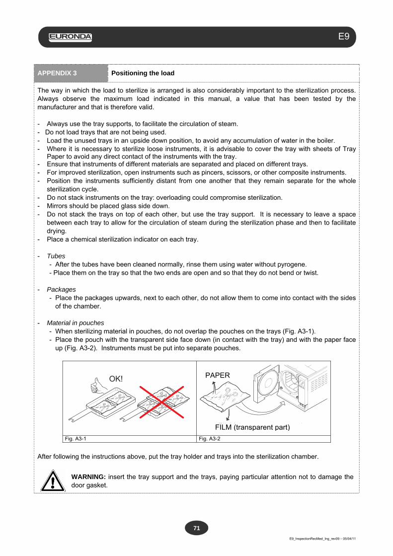
Aquafilter
E9_InspectionRecMed_Ing_rev09 – 05/04/11
71
E9
APPENDIX 3 Positioning the load
The way in which the load to sterilize is arranged is also considerably important to the sterilization process. Always observe the maximum load indicated in this manual, a value that has been tested by the manufacturer and that is therefore valid. - Always use the tray supports, to facilitate the circulation of steam. - Do not load trays that are not being used. - Load the unused trays in an upside down position, to avoid any accumulation of water in the boiler. - Where it is necessary to sterilize loose instruments, it is advisable to cover the tray with sheets of Tray
Paper to avoid any direct contact of the instruments with the tray. - Ensure that instruments of different materials are separated and placed on different trays. - For improved sterilization, open instruments such as pincers, scissors, or other composite instruments. - Position the instruments sufficiently distant from one another that they remain separate for the whole
sterilization cycle. - Do not stack instruments on the tray: overloading could compromise sterilization. - Mirrors should be placed glass side down. - Do not stack the trays on top of each other, but use the tray support. It is necessary to leave a space
between each tray to allow for the circulation of steam during the sterilization phase and then to facilitate drying.
- Place a chemical sterilization indicator on each tray. - Tubes
- After the tubes have been cleaned normally, rinse them using water without pyrogene. - Place them on the tray so that the two ends are open and so that they do not bend or twist.
- Packages - Place the packages upwards, next to each other, do not allow them to come into contact with the sides
of the chamber.
- Material in pouches - When sterilizing material in pouches, do not overlap the pouches on the trays (Fig. A3-1). - Place the pouch with the transparent side face down (in contact with the tray) and with the paper face
up (Fig. A3-2). Instruments must be put into separate pouches.
OK!
CARTA
FILM (parte trasparente)Fig. A3-1 Fig. A3-2
After following the instructions above, put the tray holder and trays into the sterilization chamber.
WARNING: insert the tray support and the trays, paying particular attention not to damage the door gasket.
PAPER
FILM (transparent part)
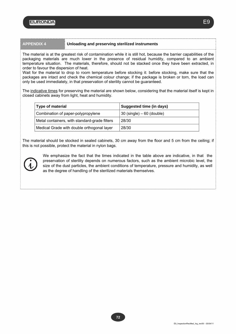
Aquafilter
E9_InspectionRecMed_Ing_rev09 – 05/04/11
72
E9
APPENDIX 4 Unloading and preserving sterilized instruments
The material is at the greatest risk of contamination while it is still hot, because the barrier capabilities of the packaging materials are much lower in the presence of residual humidity, compared to an ambient temperature situation. The materials, therefore, should not be stacked once they have been extracted, in order to favour the dispersion of heat. Wait for the material to drop to room temperature before stocking it: before stocking, make sure that the packages are intact and check the chemical colour change; if the package is broken or torn, the load can only be used immediately, in that preservation of sterility cannot be guaranteed. The indicative times for preserving the material are shown below, considering that the material itself is kept in closed cabinets away from light, heat and humidity.
Type of material Suggested time (in days)
Combination of paper-polypropylene 30 (single) – 60 (double)
Metal containers, with standard-grade filters 28/30
Medical Grade with double orthogonal layer 28/30
The material should be stocked in sealed cabinets, 30 cm away from the floor and 5 cm from the ceiling; if this is not possible, protect the material in nylon bags.
We emphasize the fact that the times indicated in the table above are indicative, in that the preservation of sterility depends on numerous factors, such as the ambient microbic level, the size of the dust particles, the ambient conditions of temperature, pressure and humidity, as well as the degree of handling of the sterilized materials themselves.
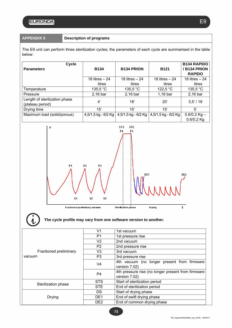
Aquafilter
E9_InspectionRecMed_Ing_rev09 – 05/04/11
73
E9
APPENDIX 5 Description of programs
The E9 unit can perform three sterilization cycles; the parameters of each cycle are summarised in the table below: Cycle Parameters B134 B134 PRION B121
B134 RAPIDO / B134 PRION
RAPIDO 18 litres – 24
litres 18 litres – 24
litres 18 litres – 24
litres 18 litres – 24
litres Temperature 135,5 °C 135,5 °C 122,5 °C 135,5 °C Pressure 2,16 bar 2,16 bar 1,16 bar 2,16 bar Length of sterilization phase (plateau period)
4’ 18’ 20’ 3,5’ / 18
Drying time 15’ 15’ 15’ 5’ Maximum load (solid/porous) 4,5/1,5 kg - 6/2 Kg 4,5/1,5 kg - 6/2 Kg
4,5/1,5 kg - 6/2 Kg 0.6/0.2 Kg –
0.6/0.2 Kg
The cycle profile may vary from one software version to another.
Fractioned preliminary vacuum
V1 1st vacuum P1 1st pressure rise V2 2nd vacuum P2 2nd pressure rise V3 3rd vacuum P3 3rd pressure rise
V4 4th vacuum (no longer present from firmware version 7.02)
P4 4th pressure rise (no longer present from firmware version 7.02)
Sterilization phase STS Start of sterilization period STE End of sterilization period
Drying DS Start of drying phase DE1 End of swift drying phase DE2 End of common drying phase
Aquafilter
E9_InspectionRecMed_Ing_rev09 – 05/04/11
74
E9
The symbols (2b, 3b, etc.) after the code of the phase refer to the software instructions. The various sterilisation cycles are now described one by one: as they are all B-type cycles, they can sterilise any type of load, whether it be porous, solid or hollow. In all cases, the recommendations given by the manufacturer regarding sterilization methods and times should be followed. Program B 121 This program is used to sterilize objects that are sensitive to temperature, as well as rubber, some articles in plastic and porous materials (cotton, fabrics) in open trays, or appropriate perforated trays. Hollow instruments and dental instruments such as tubes and similar objects can also be sterilized, after making sure that they have previously been cleaned, disinfected and rinsed. The objects indicated above can also be sterilized without the use of pouches. This program is particularly suited for sterilizing products in pouches (both single and double pouches), products that will have to be kept sterile for a long period of time. The length of this cycle depends on the weight of the load, on the type of load and on the temperature in the chamber upon start-up of the cycle. Program B 134 This program can be used both to sterilize solid instruments and porous materials (cotton, fabrics, etc.) in open trays or using the specific perforated trays. Loads arranged both in single and in double pouches can be sterilized. Hollow instruments and dental instruments such as tubes and similar objects can also be sterilized, after making sure that they have previously been cleaned, disinfected and rinsed. The objects indicated above can also be sterilized without the use of pouches. This program is particularly suited for sterilizing products in pouches, products that will have to be kept sterile for a long period of time. The length of this cycle depends on the weight of the load, on the type of load and on the temperature in the chamber upon start-up of the cycle. Program B 134 PRION - B 134 PRION RAPIDO This program is used to sterilize instruments suspected to have been contaminated by prions. The program makes it possible to sterilize articles, packed in single or in double pouches, in open trays or in specific perforated trays. Hollow instruments and dental instruments such as tubes and similar objects can also be sterilized, after making sure that they have previously been cleaned, disinfected and rinsed. The objects indicated above can also be sterilized without the use of pouches. This program is particularly suited for sterilizing boxes of products in pouches, products that will have to be kept sterile for a long period of time. The length of the cycle depends on the weight of the load, on the type of load and on the temperature in the chamber upon start-up of the cycle. Program B 134 RAPIDO For solid loads not exceeding 0,6 kg and for porous loads not exceeding 0,2 kg is possible to execute a swift cycle that allows to sterilize the load in a time of 25-28 minutes. The RAPIDO cycle includes 5 fixed minutes of drying that allows the load to get dried even if put into envelopes.
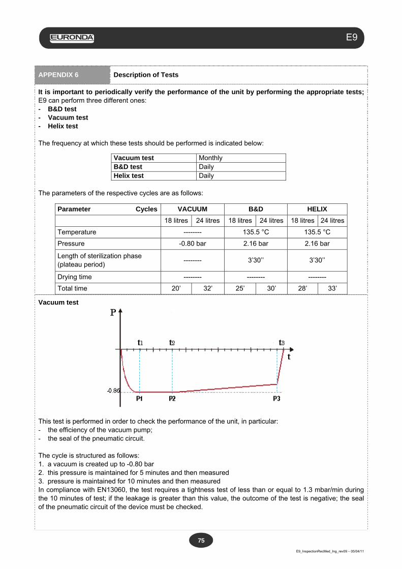
Aquafilter
E9_InspectionRecMed_Ing_rev09 – 05/04/11
75
E9
APPENDIX 6 Description of Tests
It is important to periodically verify the performance of the unit by performing the appropriate tests; E9 can perform three different ones: - B&D test - Vacuum test - Helix test The frequency at which these tests should be performed is indicated below:
Vacuum test Monthly B&D test Daily Helix test Daily
The parameters of the respective cycles are as follows:
Parameter Cycles VACUUM B&D HELIX
18 litres 24 litres 18 litres 24 litres 18 litres 24 litres
Temperature -------- 135.5 °C 135.5 °C
Pressure -0.80 bar 2.16 bar 2.16 bar
Length of sterilization phase (plateau period)
-------- 3’30’’ 3’30’’
Drying time -------- -------- --------
Total time 20’ 32’ 25’ 30’ 28’ 33’
Vacuum test
This test is performed in order to check the performance of the unit, in particular: - the efficiency of the vacuum pump; - the seal of the pneumatic circuit. The cycle is structured as follows: 1. a vacuum is created up to -0.80 bar 2. this pressure is maintained for 5 minutes and then measured 3. pressure is maintained for 10 minutes and then measured In compliance with EN13060, the test requires a tightness test of less than or equal to 1.3 mbar/min during the 10 minutes of test; if the leakage is greater than this value, the outcome of the test is negative; the seal of the pneumatic circuit of the device must be checked.
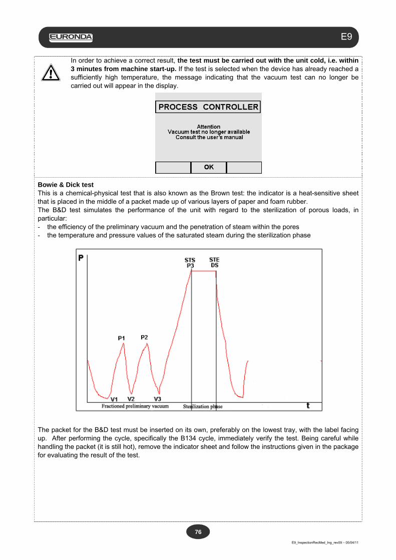
Aquafilter
E9_InspectionRecMed_Ing_rev09 – 05/04/11
76
E9
In order to achieve a correct result, the test must be carried out with the unit cold, i.e. within 3 minutes from machine start-up. If the test is selected when the device has already reached a sufficiently high temperature, the message indicating that the vacuum test can no longer be carried out will appear in the display.
Bowie & Dick test This is a chemical-physical test that is also known as the Brown test: the indicator is a heat-sensitive sheet that is placed in the middle of a packet made up of various layers of paper and foam rubber. The B&D test simulates the performance of the unit with regard to the sterilization of porous loads, in particular: - the efficiency of the preliminary vacuum and the penetration of steam within the pores - the temperature and pressure values of the saturated steam during the sterilization phase
The packet for the B&D test must be inserted on its own, preferably on the lowest tray, with the label facing up. After performing the cycle, specifically the B134 cycle, immediately verify the test. Being careful while handling the packet (it is still hot), remove the indicator sheet and follow the instructions given in the package for evaluating the result of the test.
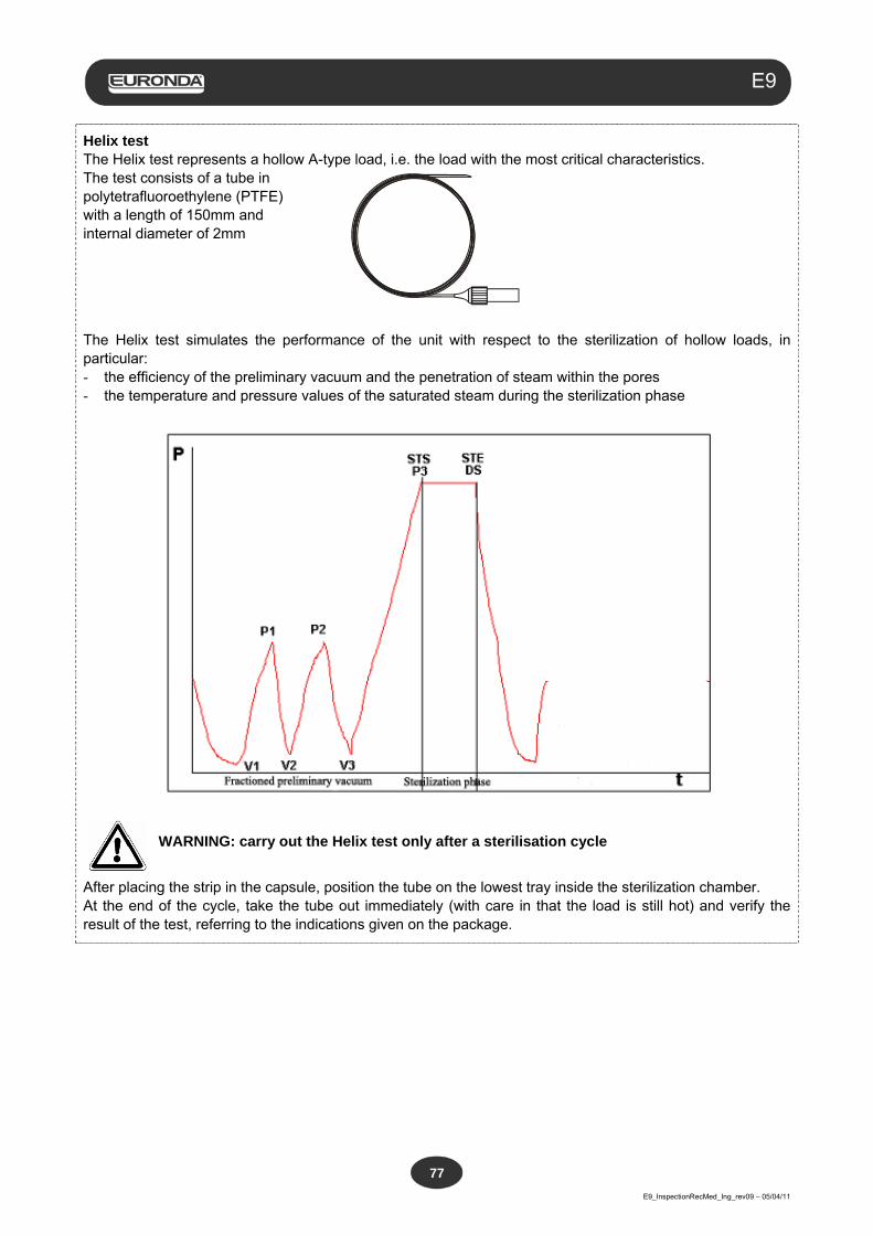
Aquafilter
E9_InspectionRecMed_Ing_rev09 – 05/04/11
77
E9
Helix test The Helix test represents a hollow A-type load, i.e. the load with the most critical characteristics. The test consists of a tube in polytetrafluoroethylene (PTFE) with a length of 150mm and internal diameter of 2mm
The Helix test simulates the performance of the unit with respect to the sterilization of hollow loads, in particular: - the efficiency of the preliminary vacuum and the penetration of steam within the pores - the temperature and pressure values of the saturated steam during the sterilization phase
WARNING: carry out the Helix test only after a sterilisation cycle
After placing the strip in the capsule, position the tube on the lowest tray inside the sterilization chamber. At the end of the cycle, take the tube out immediately (with care in that the load is still hot) and verify the result of the test, referring to the indications given on the package.
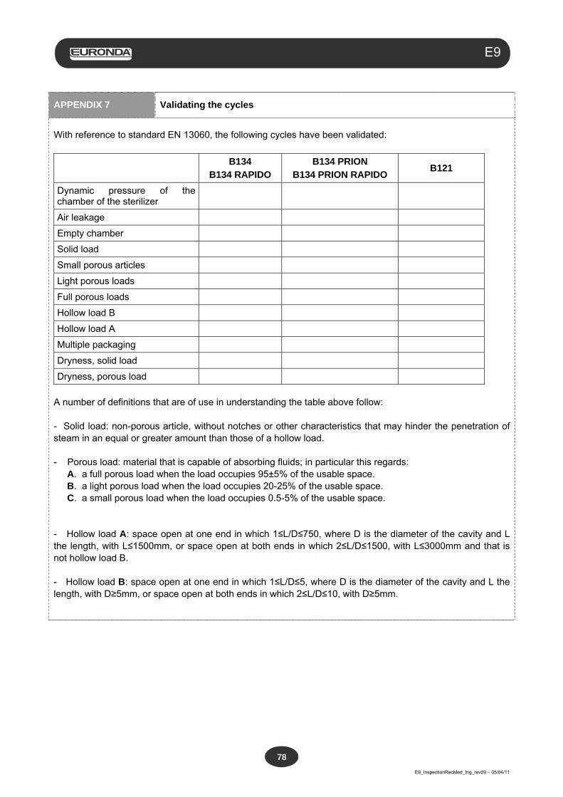
Aquafilter
E9_InspectionRecMed_Ing_rev09 – 05/04/11
78
E9
APPENDIX 7 Validating the cycles
With reference to standard EN 13060, the following cycles have been validated:
B134
B134 RAPIDO B134 PRION
B134 PRION RAPIDO B121
Dynamic pressure of the chamber of the sterilizer
Air leakage
Empty chamber
Solid load
Small porous articles
Light porous loads
Full porous loads
Hollow load B
Hollow load A
Multiple packaging
Dryness, solid load
Dryness, porous load
A number of definitions that are of use in understanding the table above follow: - Solid load: non-porous article, without notches or other characteristics that may hinder the penetration of steam in an equal or greater amount than those of a hollow load. - Porous load: material that is capable of absorbing fluids; in particular this regards:
A. a full porous load when the load occupies 95±5% of the usable space. B. a light porous load when the load occupies 20-25% of the usable space. C. a small porous load when the load occupies 0.5-5% of the usable space.
- Hollow load A: space open at one end in which 1≤L/D≤750, where D is the diameter of the cavity and L the length, with L≤1500mm, or space open at both ends in which 2≤L/D≤1500, with L≤3000mm and that is not hollow load B. - Hollow load B: space open at one end in which 1≤L/D≤5, where D is the diameter of the cavity and L the length, with D≥5mm, or space open at both ends in which 2≤L/D≤10, with D≥5mm.
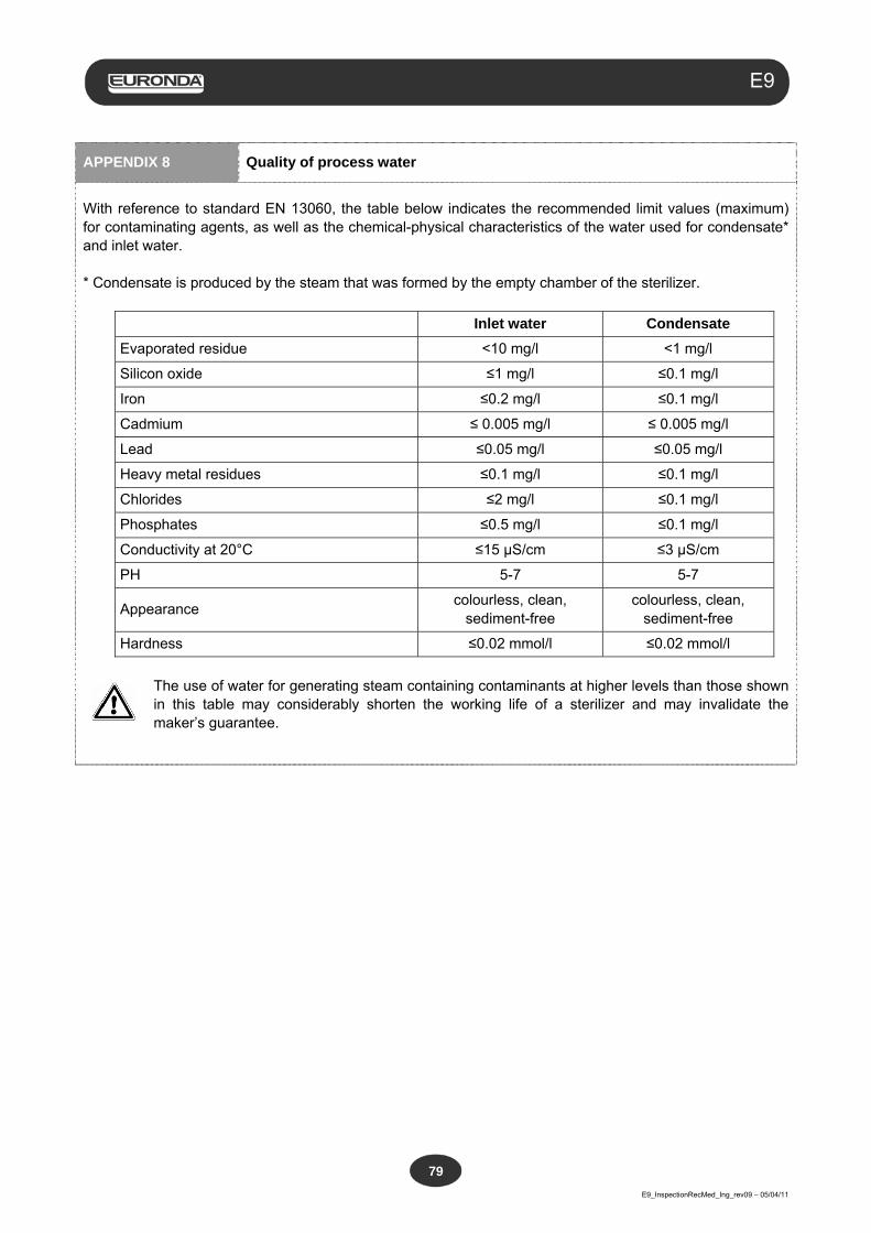
Aquafilter
E9_InspectionRecMed_Ing_rev09 – 05/04/11
79
E9
APPENDIX 8 Quality of process water
With reference to standard EN 13060, the table below indicates the recommended limit values (maximum) for contaminating agents, as well as the chemical-physical characteristics of the water used for condensate* and inlet water. * Condensate is produced by the steam that was formed by the empty chamber of the sterilizer.
Inlet water Condensate
Evaporated residue <10 mg/l <1 mg/l
Silicon oxide ≤1 mg/l ≤0.1 mg/l
Iron ≤0.2 mg/l ≤0.1 mg/l
Cadmium ≤ 0.005 mg/l ≤ 0.005 mg/l
Lead ≤0.05 mg/l ≤0.05 mg/l
Heavy metal residues ≤0.1 mg/l ≤0.1 mg/l
Chlorides ≤2 mg/l ≤0.1 mg/l
Phosphates ≤0.5 mg/l ≤0.1 mg/l
Conductivity at 20°C ≤15 µS/cm ≤3 µS/cm
PH 5-7 5-7
Appearance colourless, clean,
sediment-free colourless, clean,
sediment-free
Hardness ≤0.02 mmol/l ≤0.02 mmol/l
The use of water for generating steam containing contaminants at higher levels than those shown in this table may considerably shorten the working life of a sterilizer and may invalidate the maker’s guarantee.
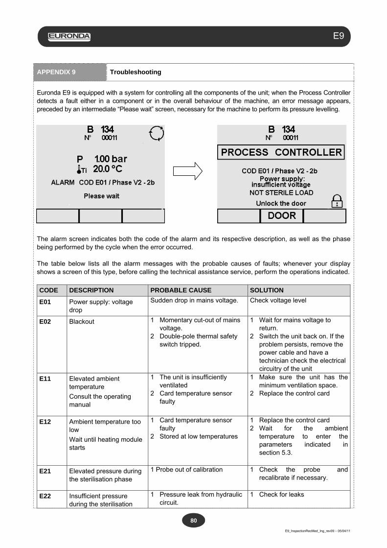
Aquafilter
E9_InspectionRecMed_Ing_rev09 – 05/04/11
80
E9
APPENDIX 9 Troubleshooting
Euronda E9 is equipped with a system for controlling all the components of the unit; when the Process Controller detects a fault either in a component or in the overall behaviour of the machine, an error message appears, preceded by an intermediate “Please wait” screen, necessary for the machine to perform its pressure levelling.
The alarm screen indicates both the code of the alarm and its respective description, as well as the phase being performed by the cycle when the error occurred. The table below lists all the alarm messages with the probable causes of faults; whenever your display shows a screen of this type, before calling the technical assistance service, perform the operations indicated.
CODE DESCRIPTION PROBABLE CAUSE SOLUTION
E01 Power supply: voltage drop
Sudden drop in mains voltage. Check voltage level
E02 Blackout 1 Momentary cut-out of mains voltage.
2 Double-pole thermal safety switch tripped.
1 Wait for mains voltage to return.
2 Switch the unit back on. If the problem persists, remove the power cable and have a technician check the electrical circuitry of the unit
E11 Elevated ambient temperature
Consult the operating manual
1 The unit is insufficiently ventilated
2 Card temperature sensor faulty
1 Make sure the unit has the minimum ventilation space.
2 Replace the control card
E12 Ambient temperature too low
Wait until heating module starts
1 Card temperature sensor faulty
2 Stored at low temperatures
1 Replace the control card 2 Wait for the ambient
temperature to enter the parameters indicated in section 5.3.
E21 Elevated pressure during the sterilisation phase
1 Probe out of calibration
1 Check the probe and recalibrate if necessary.
E22 Insufficient pressure during the sterilisation
1 Pressure leak from hydraulic circuit.
1 Check for leaks
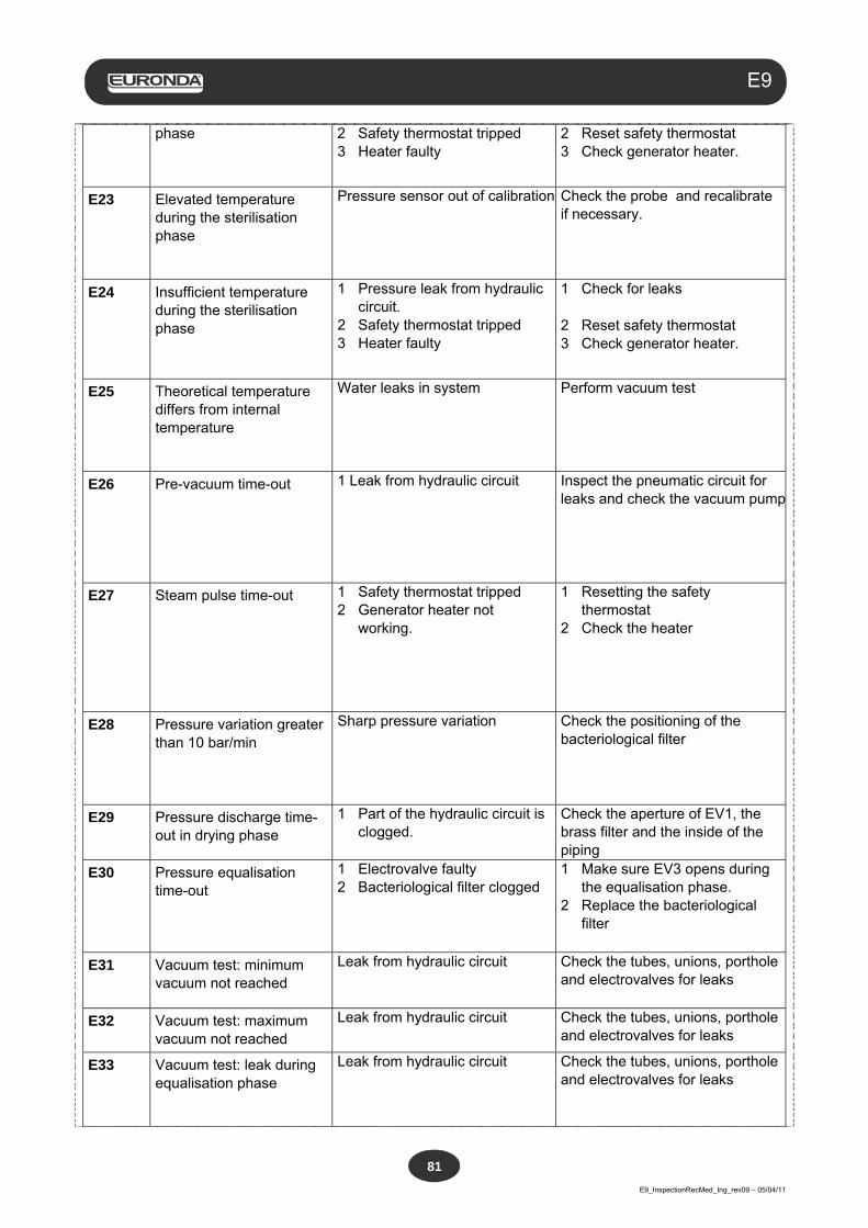
Aquafilter
E9_InspectionRecMed_Ing_rev09 – 05/04/11
81
E9
phase 2 Safety thermostat tripped 3 Heater faulty
2 Reset safety thermostat 3 Check generator heater.
E23 Elevated temperature during the sterilisation phase
Pressure sensor out of calibration
Check the probe and recalibrate if necessary.
E24 Insufficient temperature during the sterilisation phase
1 Pressure leak from hydraulic circuit.
2 Safety thermostat tripped 3 Heater faulty
1 Check for leaks 2 Reset safety thermostat 3 Check generator heater.
E25 Theoretical temperature differs from internal temperature
Water leaks in system
Perform vacuum test
E26 Pre-vacuum time-out 1 Leak from hydraulic circuit
Inspect the pneumatic circuit for leaks and check the vacuum pump
E27 Steam pulse time-out 1 Safety thermostat tripped 2 Generator heater not
working.
1 Resetting the safety thermostat
2 Check the heater
E28 Pressure variation greater than 10 bar/min
Sharp pressure variation
Check the positioning of the bacteriological filter
E29 Pressure discharge time-out in drying phase
1 Part of the hydraulic circuit is clogged.
Check the aperture of EV1, the brass filter and the inside of the piping
E30 Pressure equalisation time-out
1 Electrovalve faulty 2 Bacteriological filter clogged
1 Make sure EV3 opens during the equalisation phase.
2 Replace the bacteriological filter
E31 Vacuum test: minimum vacuum not reached
Leak from hydraulic circuit
Check the tubes, unions, porthole and electrovalves for leaks
E32 Vacuum test: maximum vacuum not reached
Leak from hydraulic circuit
Check the tubes, unions, porthole and electrovalves for leaks
E33 Vacuum test: leak during equalisation phase
Leak from hydraulic circuit
Check the tubes, unions, porthole and electrovalves for leaks
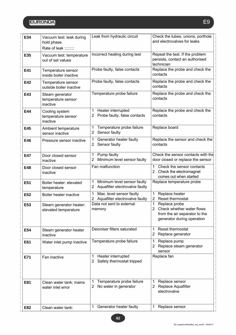
Aquafilter
E9_InspectionRecMed_Ing_rev09 – 05/04/11
82
E9
E34 Vacuum test: leak during hold phase
Rate of leak :::::::::
Leak from hydraulic circuit Check the tubes, unions, porthole and electrovalves for leaks
E35 Vacuum test: temperature out of set values
Incorrect heating during test Repeat the test. If the problem persists, contact an authorised technician
E41 Temperature sensor inside boiler inactive
Probe faulty, false contacts
Replace the probe and check the contacts
E42 Temperature sensor outside boiler inactive
Probe faulty, false contacts
Replace the probe and check the contacts
E43 Steam generator temperature sensor inactive
Temperature probe failure
Replace the probe and check the contacts
E44 Cooling system temperature sensor inactive
1 Heater interrupted 2 Probe faulty, false contacts
Replace the probe and check the contacts
E45 Ambient temperature sensor inactive
1 Temperature probe failure 2 Sensor faulty
Replace board
E46 Pressure sensor inactive 1 Generator heater faulty 2 Sensor faulty
Replace the sensor and check the contacts
E47 Door closed sensor inactive
1 Pump faulty 2 Minimum level sensor faulty
Check the sensor contacts with thedoor closed or replace the sensor
E48 Door closed sensor inactive
Fan malfunction
1 Check the sensor contacts 2 Check the electromagnet
comes out when started
E51 Boiler heater: elevated temperature
1 Minimum level sensor faulty 2 Aquafilter electrovalve faulty
Replace temperature probe
E52 Boiler heater inactive 1 Max. level sensor faulty 2 Aquafilter electrovalve faulty
1 Replace heater 2 Reset thermostat
E53 Steam generator heater: elevated temperature
Data not sent to external memory
1 Replace probe 2 Check whether water flows
from the air separator to the generator during operation
E54 Steam generator heater inactive
Deioniser filters saturated
1 Reset thermostat 2 Replace generator
E61 Water inlet pump inactive Temperature probe failure
1 Replace pump 2 Replace steam generator
sensor
E71 Fan inactive 1 Heater interrupted 2 Safety thermostat tripped
Replace fan
E81 Clean water tank: mains water inlet error
1 Temperature probe failure 2 No water in generator
1 Replace sensor 2 Replace Aquafilter
electrovalve
E82 Clean water tank: 1 Generator heater faulty 1 Replace sensor
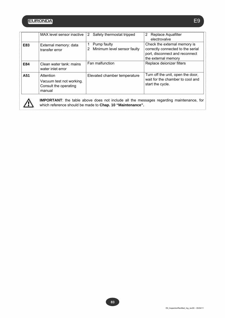
Aquafilter
E9_InspectionRecMed_Ing_rev09 – 05/04/11
83
E9
MAX level sensor inactive 2 Safety thermostat tripped
2 Replace Aquafilter electrovalve
E83 External memory: data transfer error
1 Pump faulty 2 Minimum level sensor faulty
Check the external memory is correctly connected to the serial port, disconnect and reconnect the external memory
E84 Clean water tank: mains water inlet error
Fan malfunction
Replace deionizer filters
A51 Attention
Vacuum test not working. Consult the operating manual
Elevated chamber temperature Turn off the unit, open the door, wait for the chamber to cool and start the cycle.
IMPORTANT: the table above does not include all the messages regarding maintenance, for which reference should be made to Chap. 10 “Maintenance”.

Aquafilter
E9_InspectionRecMed_Ing_rev09 – 05/04/11
84
E9
APPENDIX 10 Description of optional devices
Aquafilter Deionizer
The Aquafilter Deionizer is a device that makes it possible to obtain water for feeding the tank of the unit by connecting directly to the main water supply system. The water thus obtained has characteristics that comply with the table shown in Appendix 8. The interface between the E9 autoclave and the Aquafilter deionizer makes it possible for the deionizer to be controlled directly from the autoclave. The principle on which the system is based is that of ionic exchange: a synthetic matrix is “charged” with groups that are capable of exchanging hydrogen ions (H+) and hydroxide ions (OH-) with the cations and anions present in the water. The deionizer contains a probe used for reading the specific conductivity and is therefore capable of indicating when the characteristics of the water produced are no longer acceptable for the system. The resins are capable of producing approximately 120 litres of water, but this value is strictly dependant on the salinity of the inlet water, i.e. on the region in which the deionizer is installed. When the active sites of the resin are saturated, and the probe detects that the quality of the outlet water has a higher value than a certain pre-set value, a message for replacing the resins will appear on the display of the E9 autoclave. The quality of the water produced is also indicated by a led on the deionizer; as well as the message on the display of the unit, therefore, the red light in the led also indicates that the quality of the water produced by the deionizer is not suitable.
E-Memory-System external memory
The E9 autoclave is capable of memorizing the last 40 cycles performed. This means that inevitably the initial cycles will gradually be replaced by the last ones performed. The external memory E-memory-System (supplied with its specific software) makes it possible to memorize a few thousands of cycles and to transfer them to a Personal Computer by means of a USB cable. With the E-Memory-System software, therefore, it becomes possible to manage the cycles, to print and/or send data that refers to one or more cycles via e-mail. The connection between the E9 autoclave and the external memory is made using the front serial port.
External printer
The external printer is equipped with an 8-needle impact printing mechanism, of the rapid type, that uses plain paper. On the other hand, the printer that is integrated in the E9 uses thermal paper and, therefore, the data on the print reports is destined to fade gradually and to disappear over time. The external printer makes it possible to print the data regarding the cycle performed on plain paper and, therefore, to avoid the problems mentioned above. The connection between the E9 autoclave and the external printer is made by means of the front serial port.
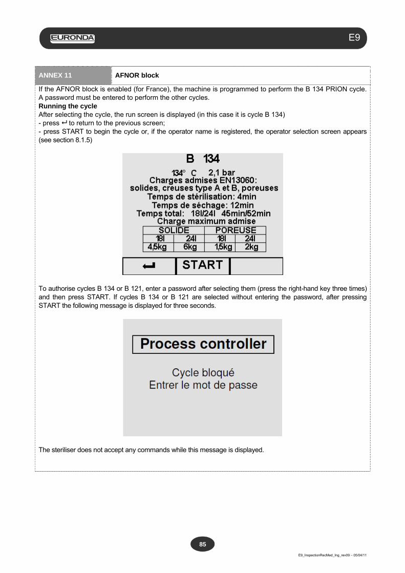
Aquafilter
E9_InspectionRecMed_Ing_rev09 – 05/04/11
85
E9
ANNEX 11 AFNOR block
If the AFNOR block is enabled (for France), the machine is programmed to perform the B 134 PRION cycle. A password must be entered to perform the other cycles.
Running the cycle After selecting the cycle, the run screen is displayed (in this case it is cycle B 134) - press to return to the previous screen; - press START to begin the cycle or, if the operator name is registered, the operator selection screen appears (see section 8.1.5)
To authorise cycles B 134 or B 121, enter a password after selecting them (press the right-hand key three times) and then press START. If cycles B 134 or B 121 are selected without entering the password, after pressing START the following message is displayed for three seconds.
The steriliser does not accept any commands while this message is displayed.

Aquafilter
E9_InspectionRecMed_Ing_rev09 – 05/04/11
86
E9
EURONDA S.p.A. Via dell'Artigianato, 7 - 36030 Montecchio Precalcino (VI) - ITALY Tel. +39 0445 329811 - Fax +39 0445 865246 - Internet: www.euronda.com - E-mail: [email protected]


