Page 1
Evaluation of Cavitation
in Hydraulic
Turbomachinery Using
STAR-CCM+
Dr. Edward M. Bennett
Vice President of Fluids Engineering
Mechanical Solutions, Inc.
Whippany, NJ07981 USA
[email protected]
7 March, 2016
11 Apollo Drive, Whippany, New Jersey 07981
Tel: (973) 326-9920 Fax: (973) 326-9919
Email: [email protected] Website: www.mechsol.com
Page 2
The Company
• Mechanical Solutions, Incorporated (MSI) is an Engineering firm
headquartered in Whippany, New Jersey USA.
• MSI specializes in fluid machinery design, fluid dynamic analysis,
and mechanical engineering design and analysis. Further
information regarding MSI can be found at www.mechsol.com.
Page 3
AGENDA
Introduction to the challenges of cavitation in hydraulic
turbomachinery
Benefits of STAR-CCM+ in addressing cavitating CFD analyses
Cavitation examples
Double suction pump
Dissolved gas in an axial pump
Cavitation instabilities in an axial inducer
Cavitation erosion prediction in a Francis turbine
Conclusions
Page 4
Cavitation Definition
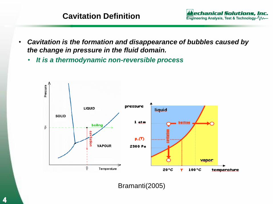
• Cavitation is the formation and disappearance of bubbles caused by
the change in pressure in the fluid domain.
• It is a thermodynamic non-reversible process
Bramanti(2005)
Page 5
Cavitation in Hydraulic Turbomachinery
• Cavitation in turbomachinery is often characterized by two variables
• Net Positive Suction Head
• NPSH =(𝑷𝒕𝟏− 𝑷𝒗𝒂𝒑𝒐𝒓)
𝞺𝒈
• Cavitation Number σ =(𝑷𝒕𝟏−𝑷𝒗𝒂𝒑𝒐𝒓)
𝟏
𝟐𝞺𝒍𝑼𝟏
𝟐, where
• Pt1 is inlet or exit total pressure
• Pvapor is vapor pressure of fluid at a given temperature
• 𝞺 is the density of the liquid(subscript l is for liquid)
• U1 is the rotational velocity
Page 6
Negative Effects of Cavitation in Hydraulic
Machinery
• Performance, Capacity and Range
• Vibration and Noise
• Dissolved or Entrained Gas in Fluid
• Cavitation Instabilities
• Cavitation Surge
• Alternate Blade Cavitation
• Rotating Cavitation Stall
• Auto-Oscillation
• Erosion and Corrosion
• Rotordynamic Instabilities
Page 7
Performance, Capacity and Range
Visser(2005)
Page 8
Dissolved or Entrained Gas in Fluid
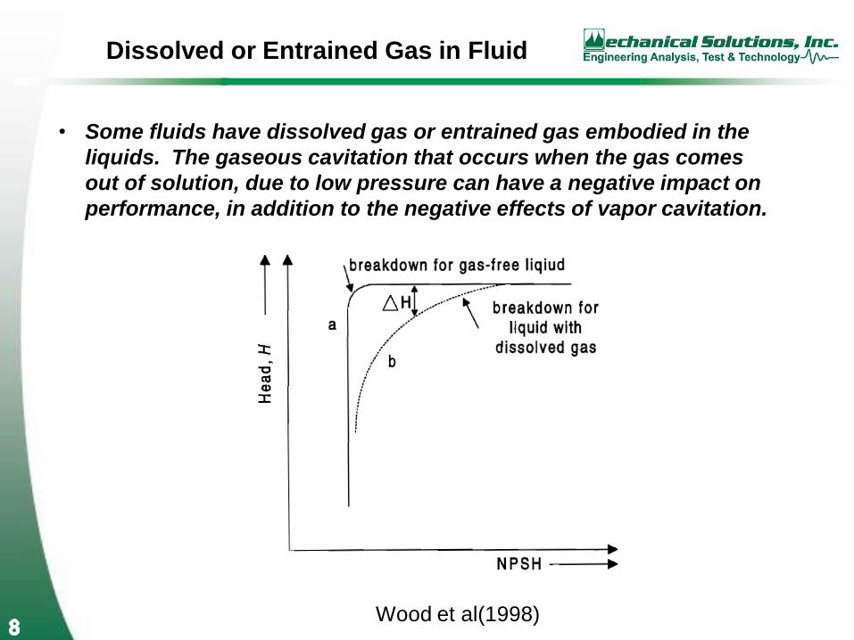
• Some fluids have dissolved gas or entrained gas embodied in the
liquids. The gaseous cavitation that occurs when the gas comes
out of solution, due to low pressure can have a negative impact on
performance, in addition to the negative effects of vapor cavitation.
Wood et al(1998)
Page 9
Cavitation Instabilities
• Cavitation is inherently unstable and unsteady. As the formation
grows, unstable effects, such as stall and auto-oscillation can have
a profound impact on the operation and mechanical integrity of
hydraulic turbomachinery
Bramanti(2005)
Page 10
Erosion and Corrosion
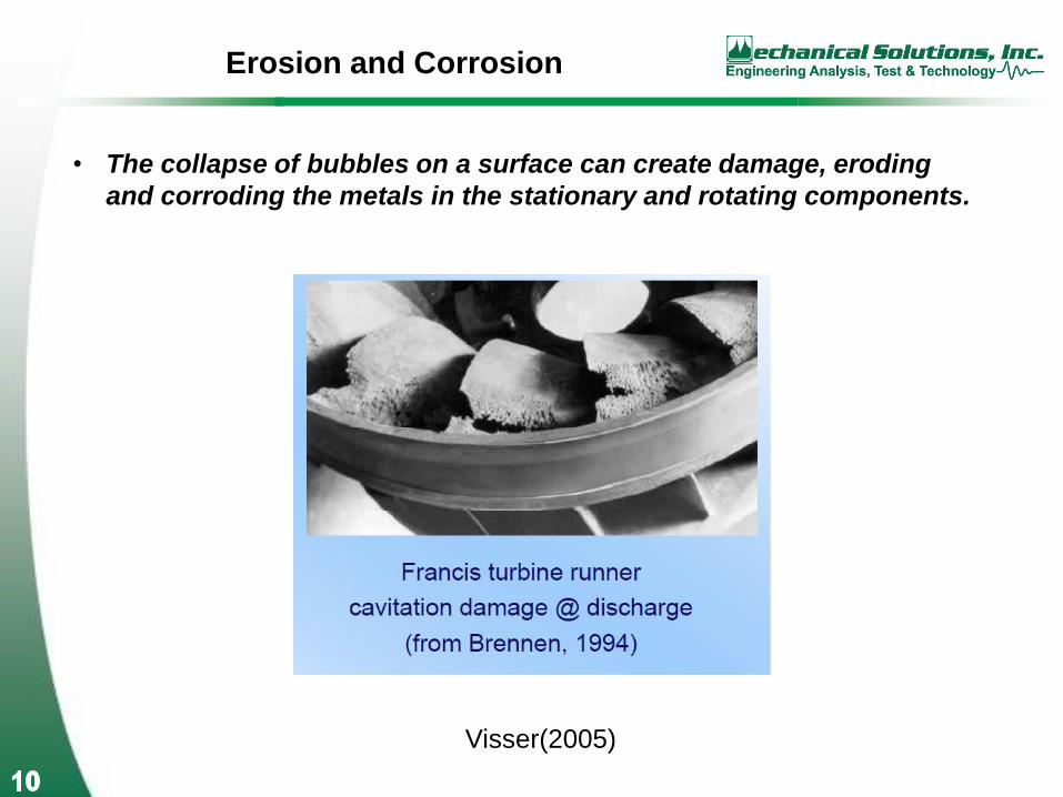
• The collapse of bubbles on a surface can create damage, eroding
and corroding the metals in the stationary and rotating components.
Visser(2005)
Page 11
Benefits of STAR-CCM+
• STAR-CCM+ has the necessary features to analyze the most
complex cavitating flows in hydraulic turbomachinery
• Advanced geometry modeling and CAD capture
• Sophisticated unstructured meshing to fully resolve cavitating
regions with detailed accuracy.
• Relevant physical models to capture advanced flow physics
• Unsteady CFD model
• Unsteady cavitation model
• Advanced turbulence models
• Advanced multiphase models to capture dissolved gas and gas entrainment
• Post-processing tools that facilitate flow diagnosis and
optimization
• Animation tools to facilitate diagnosis of cavitation instabilities
Page 12
Case Studies
• Double Suction Pump
• Dissolved Gas in Axial Pump
• Cavitation Instabilities in Axial Inducer
• Erosion in Francis Turbine
Page 13
Double-Suction Pump
Page 14
Double Suction Pump
• A complex centrifugal pump designed to enhance cavitation performance
• Flow Physics
• Complex, transient flow through 360 degrees
• Stationary and rotating domains
• Unsteady cavitation
• Relevant STAR-CCM+ features to facilitate a solution
• Unsteady flow solver
• Unsteady cavitation model
• Unsteady stationary/rotating interfaces
• Advanced unstructured CFD meshing from CAD geometry
• Parallel capability for large size and economical time to solution
Page 15
Flowpath Geometry
Suction Inlet
Volute
Impeller
Page 16
Mesh in STAR-CCM+
Note: Single-vane mesh for impeller was cyclically patterned and fused to
ensure mesh uniformity.
Page 17
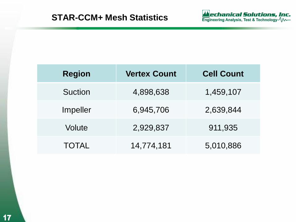
STAR-CCM+ Mesh Statistics
Region Vertex Count Cell Count
Suction 4,898,638 1,459,107
Impeller 6,945,706 2,639,844
Volute 2,929,837 911,935
TOTAL 14,774,181 5,010,886
Page 18
STAR-CCM+ Model Setup
• SST k-ω turbulence model
• Segregated flow solver
• 2nd-order convection scheme
• Multi-phase Volume of Fluid (VOF) model
• Rayleigh-Plesset cavitation model
• Boundary conditions:
- Inlet total pressure via pressure reference point
- Rotating speed on Impeller region
- Inlet and exit mass flow
• Transient timestep set to match 360 steps per revolution
• 20 inner iterations per timestep
• Simulation ran until residual plots and monitor value plots
(such as pressure, torque and mass flow) were judged to
have settled
Page 19
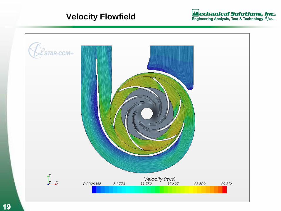
Velocity Flowfield
Page 20
Pressure Contours
Page 22
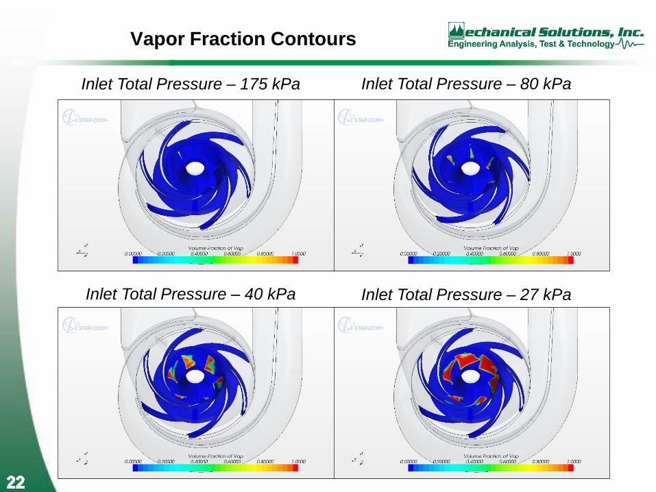
Vapor Fraction Contours
Inlet Total Pressure – 175 kPa Inlet Total Pressure – 80 kPa
Inlet Total Pressure – 40 kPa Inlet Total Pressure – 27 kPa
Page 23
Comparison of Cavitation Breakdown Curves
Page 24
Comparison of Cavitation Breakdown Curves
Page 25
Comparison of Cavitation Breakdown Curves
Page 26
Flow Animations
• Flow animations can be an invaluable tool in assessing
cavitating flows in pumps.
• Flow symmetry can be determined qualitatively as well as
quantitatively.
• Cavitation can be observed in other components than the
impeller, such as the radial inlet, or diffuser passage.
• STAR-CCM+ provides post-processing that facilitate
excellent flow animations.
Page 27
Cavitation Animation
Page 28
Cavitation Animation
Page 29
Low NPSHr Axial Pump with Dissolved Gas
• An axial pump was designed for an industrial application.
• The pump had to operate with a low Net Positive Suction Head
(NPSH)
• The pump satisfied the requirements, but did not have the NPSHr
margin predicted.
• An investigation was conducted to determine the source of the
variance.
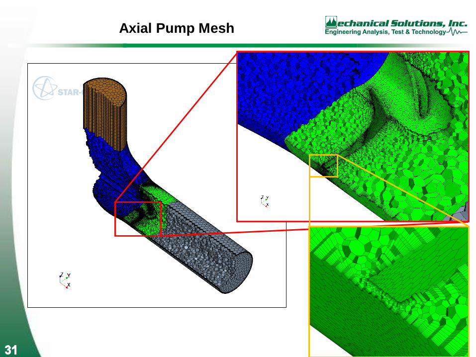
Page 30
Axial Pump Flowpath Geometry
Inlet Pipe
Impeller
Outlet Pipe
Elbow
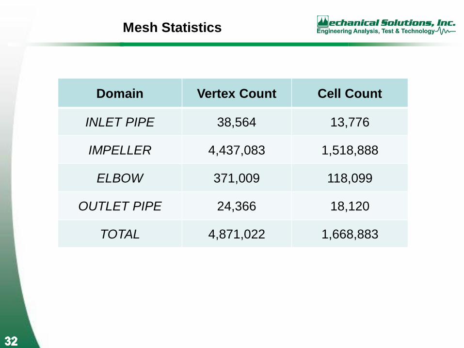
Page 32
Mesh Statistics
Domain Vertex Count Cell Count
INLET PIPE 38,564 13,776
IMPELLER 4,437,083 1,518,888
ELBOW 371,009 118,099
OUTLET PIPE 24,366 18,120
TOTAL 4,871,022 1,668,883
Page 33
CFD Model Setup
• Realizable k-ε turbulence model
• Segregated flow solver with 2nd-order convection scheme
• VOF multiphase model with Rayleigh-Plesset cavitation model
• Water and water vapor at 68 °F as working fluids
• Boundary conditions:
- Stagnation inlet
- Rotating speed on Impeller region
- Exit mass flow
• Transient timestep set to match 360 steps per revolution
• 20 iterations per step
• Simulation ran until residual plots and monitor value plots
(such as pressure, torque and mass flow) were judged to have
settled
Page 34
Axial Pump Streamlines
Page 35
Axial Pump Cavitation
Page 36
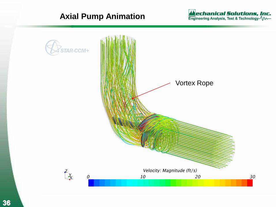
Axial Pump Animation
Vortex Rope
Page 37
Predicted Cavitation Breakdown Curves
Page 38
Inclusion of Dissolved Gas
• Customer testing demonstrated cavitation breakdown was
greater than the predicted value.
• The water used for the test was left alone in a tank for several
days to eliminate entrained air; however, the water was not de-
aerated for the test
• Air dissolved in water was hypothesized as a potential source
of variance between the test and the CFD, which considered no
dissolved air in the solution.
• Dissolved gas model added to CFD setup
• Based on Henry’s Law
• Water replaced with mixture of water and air (1.2%)
• Water vapor replaced with mixture of vapor and air
• Model was rerun at 100% flow with previous boundary
conditions
Page 39
Axial Pump Cavitation with Dissolved Gas
Page 40
Cavitation Breakdown Curves
with Dissolved Gas
Inclusion of dissolved air causes pump
to have a greater NPSHr, within 2% of test results.
Page 41
Axial Inducer with Cavitation Instabilities
• Axial inducers are used to boost pressure and improve cavitation
performance
• They are used in the following applications.
• High energy pumps
• Rocket turbopumps
• LNG pumps
• Fire suppression pumps
Page 42
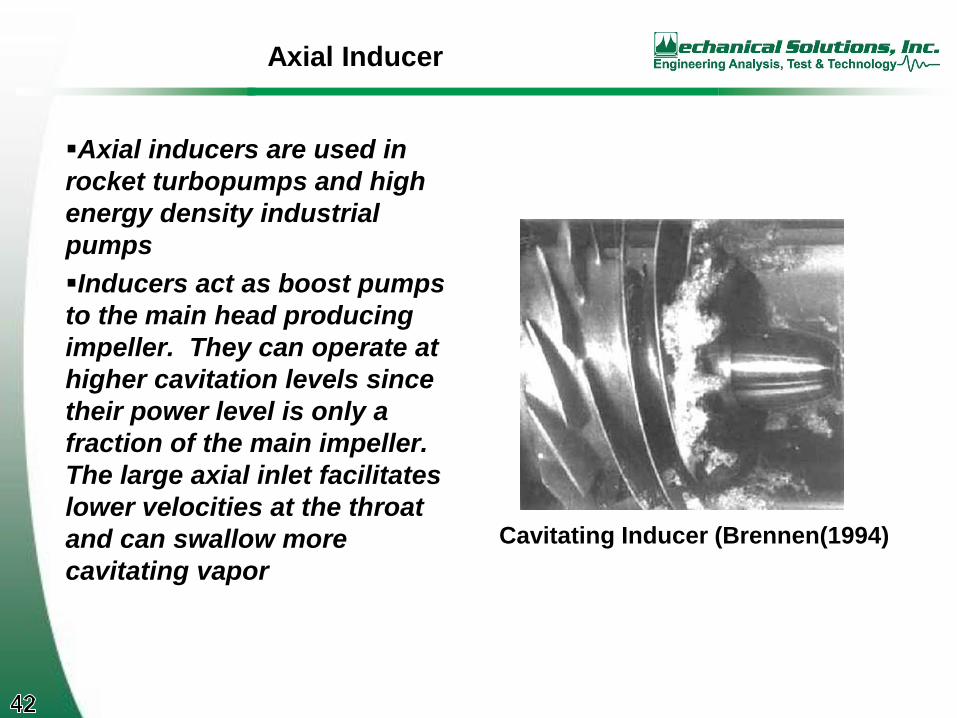
Axial Inducer
Axial inducers are used in
rocket turbopumps and high
energy density industrial
pumps
Inducers act as boost pumps
to the main head producing
impeller. They can operate at
higher cavitation levels since
their power level is only a
fraction of the main impeller.
The large axial inlet facilitates
lower velocities at the throat
and can swallow more
cavitating vapor
Cavitating Inducer (Brennen(1994)
Page 43
Axial Inducer Test Case
• Test inducer described in Bennett(2009) serves as test case
• Test case based upon NASA FASTRAC LOX inducer
• Test geometry developed using CFturbo design software
Page 44
Inducer Test Geometry
Inducer
Volute
Inlet
“Bladeless Impeller Passage
Page 45
Inducer Mesh
• Single-vane sector mesh for inducer was patterned and fused to ensure mesh uniformity
Page 46
Mesh Statistics
Domain Cells Faces Vertexes
Inlet 122,386 441,586 221,844
Inducer 1,250,682 5,806,662 3,763,724
Impeller 129,712 566,488 360,244
Volute 84,496 360,112 220,411
TOTAL 1,587,276 7,174,848 4,566,223
Page 47
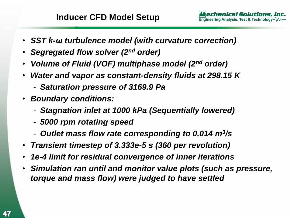
Inducer CFD Model Setup
• SST k-ω turbulence model (with curvature correction)
• Segregated flow solver (2nd order)
• Volume of Fluid (VOF) multiphase model (2nd order)
• Water and vapor as constant-density fluids at 298.15 K
- Saturation pressure of 3169.9 Pa
• Boundary conditions:
- Stagnation inlet at 1000 kPa (Sequentially lowered)
- 5000 rpm rotating speed
- Outlet mass flow rate corresponding to 0.014 m3/s
• Transient timestep of 3.333e-5 s (360 per revolution)
• 1e-4 limit for residual convergence of inner iterations
• Simulation ran until and monitor value plots (such as pressure,
torque and mass flow) were judged to have settled
Page 48
Inducer Performance Summary
Suction
Specific
Speed
NPSHa
[m]
Inlet Total
Pressure
[kPa]
Outlet Total
Pressure
[kPa]
Inducer
Head
[m]
Inducer
Torque
[N-m]
Inducer
Efficiency
18.4 102.0 1000.2 1097.0 9.9 3.174 81.5%
31.1 50.8 500.3 597.7 10.0 3.175 82.0%
105.8 9.9 100.2 200.9 10.3 3.278 82.2%
183.1 4.8 49.9 155.6 10.8 3.441 82.2%
400.5 1.7 19.6 126.9 11.0 3.517 81.6%
518.3 1.2 14.8 119.4 10.7 3.544 78.9%
598.8 1.0 12.8 99.9 8.9 3.158 73.7%
646.9 0.9 11.8 93.3 8.3 2.977 73.1%
All results were averaged over several revolutions (as many as 27 for highly-cavitating cases)
Page 49
Inducer NPSH Breakdown Curve
Page 50
Inducer Cavitation
0.3 vapor fraction isosurface
20 kPa inlet total pressure
Page 51
Inducer Pressure Probe Locations
Page 52
Inducer Probe Traces
Page 53
Inducer Probe FFT Analysis
Multiples of Vane Pass
0.26Ω, potential auto-oscillation
Page 54
Typical Pump Cavitation Instability
Frequencies
Bramanti(2005)
Page 55
Animation of Inducer at Inlet Pressure = 20 kPa
Page 56
Animation of Inducer at Inlet Pressure = 12 kPa
Page 57
Cavitation in Francis Turbine
Page 58
Cavitation in Francis Turbine
• Erosion takes place when vapor bubbles collapse near a wall
• Quantitative analysis is difficult because erosion is a slow
process, so a qualitative approach is preferable
• Several functions can be evaluated and plotted on the walls to
calibrate against experimental data (if available)
• Vapor bubble radius
• Rate of change of vapor bubble radius
• Rate of change of vapor bubble volume
• Second derivative of vapor bubble volume with respect to time
Page 59
Rate of Change of Bubble Radius
The general Rayleigh-Plesset equation is:
The single-component bubble growth rate can be estimated using the
inertia-controlled growth model, which discounts viscous and surface
tension effects. Therefore:
Erosion rate could be proportional to rate of bubble collapse.
𝑑𝑅
𝑑𝑡= 𝑠𝑖𝑔𝑛(𝑝𝑣𝑎𝑝𝑜𝑟 − 𝑝𝑙𝑜𝑐𝑎𝑙)
2
3
𝑝𝑣𝑎𝑝𝑜𝑟 − 𝑝𝑙𝑜𝑐𝑎𝑙
𝜌𝑙𝑖𝑞𝑢𝑖𝑑
𝑝𝑣𝑎𝑝𝑜𝑟 − 𝑝𝑙𝑜𝑐𝑎𝑙
𝜌𝑙𝑖𝑞𝑢𝑖𝑑= 𝑅
𝑑2𝑅
𝑑𝑡2+3
2
𝑑𝑅
𝑑𝑡
2
+4𝜈𝑙𝑖𝑞𝑢𝑖𝑑
𝑅
𝑑𝑅
𝑑𝑡+
2𝜎
𝜌𝑙𝑖𝑞𝑢𝑖𝑑𝑅
Page 60
Rate of Change of Bubble Radius
Page 61
Rate of Change of Bubble Volume
The seed-based cavitation model proposes the following volume relation
between vapor and liquid phases:
𝑉𝑣𝑎𝑝𝑜𝑟 = 𝑛0𝑉𝑙𝑖𝑞𝑢𝑖𝑑4
3𝜋𝑅3,
where 𝑛0 is the seed density, or the number of bubbles per unit volume.
It also states that:
𝛼𝑣𝑎𝑝𝑜𝑟 =𝑉𝑣𝑎𝑝𝑜𝑟
𝑉𝑡𝑜𝑡𝑎𝑙=
𝑉𝑣𝑎𝑝𝑜𝑟
𝑉𝑣𝑎𝑝𝑜𝑟 + 𝑉𝑙𝑖𝑞𝑢𝑖𝑑=
𝑛0𝑉𝑙𝑖𝑞𝑢𝑖𝑑43𝜋𝑅3
𝑛0𝑉𝑙𝑖𝑞𝑢𝑖𝑑43𝜋𝑅3 + 𝑉𝑙𝑖𝑞𝑢𝑖𝑑
=𝑛0
43𝜋𝑅3
𝑛043𝜋𝑅3 + 1
Therefore:
𝑅 =𝛼𝑣𝑎𝑝𝑜𝑟
𝑛043𝜋(1 − 𝛼𝑣𝑎𝑝𝑜𝑟)
13
Page 62
Rate of Change of Bubble Volume
The rate of change of bubble volume is then:
𝑑𝑉𝑣𝑎𝑝𝑜𝑟
𝑑𝑡= 𝑛0(1 − 𝛼𝑣𝑎𝑝𝑜𝑟)4𝜋𝑅
2𝑑𝑅
𝑑𝑡
at which point one can plug in the above equations for 𝑅 and 𝑑𝑅
𝑑𝑡.
𝑑𝑉𝑣𝑎𝑝𝑜𝑟
𝑑𝑡= 𝑛0 1 − 𝛼𝑣𝑎𝑝𝑜𝑟 4𝜋
𝛼𝑣𝑎𝑝𝑜𝑟
𝑛04
3𝜋 1−𝛼𝑣𝑎𝑝𝑜𝑟
2
3×
× 𝑠𝑖𝑔𝑛(𝑝𝑣𝑎𝑝𝑜𝑟 − 𝑝𝑙𝑜𝑐𝑎𝑙)2
3
𝑝𝑣𝑎𝑝𝑜𝑟−𝑝𝑙𝑜𝑐𝑎𝑙
𝜌𝑙𝑖𝑞𝑢𝑖𝑑
Page 63
Rate of Change of Bubble Volume
Page 64
Second derivative of bubble volume
with respect to time
Presume that erosion is proportional to 𝑑2𝑉
𝑑𝑡2.
From the equation for bubble volume, it follows that:
𝑑2𝑉
𝑑𝑡2= 4𝜋𝑅2
𝑑2𝑅
𝑑𝑡2+ 8𝜋𝑅
𝑑𝑅
𝑑𝑡
2
To simplify, one can dismiss the 𝑑2𝑅
𝑑𝑡2term, since
𝑑𝑅
𝑑𝑡is only a function of
pressure, which is not changing in a quasi-steady flow. Therefore:
𝑑2𝑉𝑣𝑎𝑝𝑜𝑟
𝑑𝑡2∝ 8𝜋𝑅
𝑑𝑅
𝑑𝑡
2
at which point one can again plug in the equations for 𝑅 and 𝑑𝑅
𝑑𝑡.
Page 65
Second derivative of bubble volume
with respect to time
Page 66
Cavitation Erosion Summary
Page 67
Quantitative Runner Erosion Prediction
Visser(2005)
Method involves the use of surface cavity length, fluid and metal properties, and
basic hydraulic properties of the runner flow domain
Page 68
Quantitative Runner Erosion Prediction
Typical MSI Erosion Rate Spreadsheet
Page 69
CONCLUSIONS
• STAR-CCM+ is an extremely valuable tool for analyzing the flow
through hydraulic turbomachinery
• The unsteady cavitation model has been successful in resolving the
various forms of cavitation that are specific to hydraulic
turbomachinery
Page 70
Acknowledgment
• Mechanical Solutions is grateful for the ongoing support and
technical service provided by CD-adapco.
Page 71
References
1. Bennett, E., “Advanced Methodology for Low NPSH Axial Pump
Inducers”, ASME Fluids Engineering Division Summer Meeting,
2009.
2. Bramanti, C., “Experimental Study of Cavitation and Flow
Instabilities in Space Rocket Turbopumps and Hydrofoils”,
University of Pisa Doctoral Dissertation, 2005.
3. Wood, D., et al, “Application Guidelines for Pumping Liquids That
Have a Large Dissolved Gas Content”, 15th Texas A&M Pump
Symposium, 1998.
4. Visser, F., “Cavitation in Centrifugal Pumps and Prediction
Thereof”, Tutorial, 2005 ASME Fluids Engineering Division Summer
Conference, 2005.