Full Terms & Conditions of access and use can be found at http://www.tandfonline.com/action/journalInformation?journalCode=tcoi20 Download by: [91.227.24.154] Date: 04 January 2016, At: 00:27 Composite Interfaces ISSN: 0927-6440 (Print) 1568-5543 (Online) Journal homepage: http://www.tandfonline.com/loi/tcoi20 Evaluation of mechanical and thermal properties of microwave irradiated poly (styrene-co-methyl methacrylate)/graphene nanocomposites Mukarram Zubair, Jobin Jose & Mamdouh A. Al-Harthi To cite this article: Mukarram Zubair, Jobin Jose & Mamdouh A. Al-Harthi (2015) Evaluation of mechanical and thermal properties of microwave irradiated poly (styrene-co-methyl methacrylate)/graphene nanocomposites, Composite Interfaces, 22:7, 595-610, DOI: 10.1080/09276440.2015.1055960 To link to this article: http://dx.doi.org/10.1080/09276440.2015.1055960 Published online: 19 Jun 2015. Submit your article to this journal Article views: 59 View related articles View Crossmark data
Transcript
Full Terms & Conditions of access and use can be found athttp://www.tandfonline.com/action/journalInformation?journalCode=tcoi20
Download by: [91.227.24.154] Date: 04 January 2016, At: 00:27
Evaluation of mechanical and thermal propertiesof microwave irradiated poly (styrene-co-methylmethacrylate)/graphene nanocomposites
Mukarram Zubair, Jobin Jose & Mamdouh A. Al-Harthi
To cite this article: Mukarram Zubair, Jobin Jose & Mamdouh A. Al-Harthi (2015) Evaluationof mechanical and thermal properties of microwave irradiated poly (styrene-co-methylmethacrylate)/graphene nanocomposites, Composite Interfaces, 22:7, 595-610, DOI:10.1080/09276440.2015.1055960
To link to this article: http://dx.doi.org/10.1080/09276440.2015.1055960
Evaluation of mechanical and thermal properties of microwaveirradiated poly (styrene-co-methyl methacrylate)/graphene
nanocomposites
Mukarram Zubaira, Jobin Joseb and Mamdouh A. Al-Harthic,d*
aDepartment of Environmental Engineering, University of Dammam, Dammam 31982,Saudi Arabia; bCenter for Engineering Research, King Fahd University of Petroleum & Minerals,Dhahran 31261, Saudi Arabia; cDepartment of Chemical Engineering, King Fahd University of
Petroleum & Minerals, Dhahran 31261, Saudi Arabia; dCenter of Research Excellence inNanotechnology, King Fahd University of Petroleum & Minerals, Dhahran 31261, Saudi Arabia
(Received 4 February 2015; accepted 26 May 2015)
Poly (styrene-co-methyl methacrylate) (P(S-co-MMA)) was blended with pristinegraphene (G) by melt mixing technique and treated under microwave irradiation.The nanocomposites were irradiated for 5 and 10 min at frequency 1245 MHz.Structure changes in the irradiated nanocomposites were observed by Fourier trans-form infrared spectroscopy and Raman spectroscopy. The irradiated compositesshowed a significant increase in the storage modulus i.e. 21% for 0.1% and 31% for1% graphene polymer composites after 5 min irradiation. However at higher irradia-tion (10 min), degradation of nanocomposites was observed. The concept ofimprovement of interfacial interaction between graphene and P(S-co-MMA) chainsat 5-min microwave exposure and degradation of nanocomposites at higher irradia-tion duration was assessed and supported by X-ray diffraction and scanning electronmicroscopy.
During the past two decades, nanocomposites, especially carbon-based nanomaterials,have become a novel class of material. When incorporated into a polymer matrix, theyhave revealed remarkably improved properties, at very low loading contents. In particu-lar, graphene and its polymer composites have attracted tremendous applications inmodern science and technology.[1,3] Being the ‘thinnest material’ in the universe, itsunique properties make graphene more demanding in different technological fields suchas conducting films,[4] sensors,[5] super capacitors,[6] nanoelectronics,[7] batteries,[8]and bio-medical applications.[9]
Polystyrene and poly (methyl methacrylate) are widely used commodity plasticsafter polyolefin. They are productively applied in different fields such as bio materials,protective coatings, microelectronics, tissue engineering, and solar technology.[10–13]Incorporation of nanofillers such as carbon nanotubes and graphene into the polymermatrix can considerably enhance mechanical and thermal properties,[2,14,15] which isdesirable for different kinds of applications.
Melt mixing is a widely used technique to prepare polymer nanocomposites. It isan easy, economical, and efficient technique in which high temperature and strong shearforces are employed to obtain efficient mixing between polymer matrix and nanofiller.During melt mixing, the polymer chains may degrade.[16] This can lead to betterdispersion and covalent bond formation of nanofillers with the polymer chains.[17] Toachieve full improvement in the properties of polymer/nanofiller composites, the mostchallenging step is to achieve a high level of homogenous dispersion and interactionbetween the nanofiller and the polymer matrix. Different approaches such as the use ofperoxide during melt mixing,[18] functionalization of nanoparticles [19–21] andimplication of low molecular weight polymer chains [22] have been investigated, butscientists are still looking for a more appropriate method to attain better interactionbetween the graphene and the polymer matrix.
Irradiation is a widely accepted and useful technique to modify the properties ofpolymer nanocomposites.[23] The irradiation process causes major reactions such ascross-linking, chain scission (degradation), formation of oxygen-based functionalities(oxidation), and grafting (in the presence of monomers).[24] Similarly, when radiationis absorbed on the surface of graphene, defects form on graphene [25] which results ina change of the structure of graphene. This free radical formation in polymer chainsand disorder in graphene structure after irradiation may provide improved dispersionand hence a strong interfacial interaction between the graphene and the polymer matrix.Compared to other radiation techniques, microwave radiation is an fast, cheap, andgreen technique.[26] It was extensively used for synthesis of polymer composites [27],but so far very few studies has been performed [28,29] to investigate the improvementof interaction between graphene and copolymer composites using microwave radiation.
In this article, the poly (styrene-co-methyl methacrylate) (P(S-co-MMA))/graphenecomposites were prepared via melt blending and exposed to microwave radiation. Theresultant samples were characterized by various techniques to study the influence ofmelt blending, filler content, and particularly microwave radiation on the interactionbetween P(S-co-MMA) and graphene.
2. Experimental
2.1. Materials
Styrene (99%), methyl methacrylate (MMA, 99%), and benzoyl peroxide werepurchased from Sigma-Aldrich and used as received. Tetrahydrofuran (THF) andmethanol were obtained from Pure Chemika. Graphene (96–99%, 50–100 nm) waspurchased from Grafen Chemical Industries Co. (Turkey).
2.2. Synthesis of poly (styrene methyl methacrylate) copolymer
P(S-co-MMA) copolymer is produced by free radical polymerization. Benzoyl peroxideof 0.1 wt% of the total volume of monomers was used as an initiator. Reaction wascarried out in a round bottom flask equipped with a magnetic stirrer at 110 °C for 5 hunder a nitrogen environment. After the reaction, THF (60 ml per 10 ml of monomer)was added to the round bottom flask and stirred for 2–4 days to dissolve the product.The dissolved polymer solution was precipitated with an excess amount of methanoland then dried in an oven at 40 °C for 24 h.
596 M. Zubair et al.
Dow
nloa
ded
by [
] at
00:
27 0
4 Ja
nuar
y 20
16
2.3. Preparation of poly (styrene methyl methacrylate)/graphene (PG) composite
P(S-co-MMA)/graphene nanocomposites were prepared using a Brabender torquerheometer. Different percentages of graphene (0.1, 0.3, and 1 wt%) were added to P(S-co-MMA) copolymer and mixed for 10 min at a temperature of 180 °C at a speedof 60 rpm. Thin sheets of the composites with an approximate thickness of 1 mm wereprepared by compression molding for 8 min at a temperature of 140 °C under a pres-sure of 97 MPa and cooled to room temperature. Table 1 illustrates the composition ofdifferent samples produced in this study.
2.4. Microwave irradiation method
The microwave irradiation of the P(S-co-MMA)/graphene composite was carried out atfrequency of 2450 MHz at fixed power of 1000 W with different treatment times. Theirradiation was carried out using a domestic microwave oven with an internal turntable.
The details of the procedure for irradiation of the samples are given below.
• Samples of dimension (4 × 10 × 1 mm) were treated at different treatment timesat a constant power of 1000 W in the presence of air.
• The samples were irradiated at two different durations (5 and 10 min) with 60 sfor each cycle in the presence of air. After each cycle of irradiation, the samplewas cooled to room temperature (taking about 120 s) to avoid the effect of heaton the polymer graphene composite sample.
2.5. Characterization
2.5.1. Spectroscopic analysis
The FTIR spectra were recorded using a Nicolet 6700 spectrometer with resolution of4 cm−1. The functional groups such as carbonyl and hydroxyl groups were comparedbefore and after irradiation in a band range of 1700–1725 and 3000–3450 cm−1, respec-tively. For Raman spectroscopy, a Raman Aramis (Horiba JobinYvon) instrument withlaser power of 0.7 mW and wavelength of 473 nm was used. The composition ofstyrene and methyl methacrylate in the co-polymer was calculated using NMR spectraestimated at room temperature using a Bruker 500 MHz spectrometer at resonancefrequency of 500 MHz.
2.5.2. Dynamic mechanical analysis
The dynamic mechanical properties of the samples before and after irradiation wereinvestigated in a temperature range from 40 to 160 °C in the tension mode at a heating
Table 1. Composition of P(S-co-MMA) and its composites.
rate of 5 °C/min and a frequency of 1 Hz using a Perkin Elmer DMA Q-800. Thedynamic mechanical properties were tested under nitrogen environment at a load of5 N with the average sample size 4 × 10 × 1 mm.
2.5.3. Differential scanning calorimetry
The glass transition temperature of the samples was determined using DSC-Q1000, TAinstrument. Samples were weighed to ±0.5 mg accuracy, and experiments were carriedout in nitrogen environment. The first stage of heating was carried out to remove thethermal history of the sample if any. The cooling step was done at a rate of 5 °C/min,and the final heating at a rate of 10 °C/min was carried out to determine the Tg of thesample.
2.5.4. X-ray diffraction
X-ray diffraction (XRD) studies were carried out using a D8 Advance X-ray Instrumentwith wavelength of λ = 0.154 nm and 2θ range from 2° to 70°. The scanning rate was1°/min.
2.5.5. Electrical conductivity
Electrical conductivity measurement was carried out using a four probe AITSR-2000N/PV machine at a current of 10 nA and 2 V.
2.5.6. Scanning electron microscopy (SEM)
Scanning electron microscopy were taken using a JSM-6460LV (Jeol) SEM. Prior tothe experiment, the samples were cryo-fractured using liquid nitrogen and the crosssection was sputter coated with gold for 2 min to make the surface conductive.
3. Results and discussion
The possible mechanism of P(S-co-MMA)/graphene nanocomposites formation via meltblending and the effect of microwave irradiation are shown in Scheme 1. Melt blendingat high shear and high temperature can lead to attachment of the polymer chains ontothe graphene platelets. The irradiation caused free radical formation on polymer chainsand surface modification of graphene which eventually leads to better interactionbetween them.
3.1. FTIR analysis
Figure 1(a) shows the FTIR spectra of graphene. Figure 1(b) and (c) show the FTIRspectra of non-irradiated and irradiated P(S-co-MMA) and its composites. In Figure 1(a),the peak in graphene spectra at 2928 and 2865 cm−1 represents the C–H stretch vibra-tions of the methylene group.[30] The FTIR spectra’s of non-irradiated and irradiatedcomposites showed the similar trend of bands compared to control P(S-co-MMA), withan increase or even disappeared in the intensity of the some absorption band foundafter melt mixing and microwave irradiation.
In non-irradiated PG(0.1) and PG(1), the intensity of carbonyl stretching vibrationpeak at 1725 cm−1 was decreased to low intensity as compared to P(S-co-MMA). This
598 M. Zubair et al.
Dow
nloa
ded
by [
] at
00:
27 0
4 Ja
nuar
y 20
16
may be due to the interaction of graphene with the methyl acrylate (COOCH3)functionality in a polymer matrix after melt mixing.[31] In addition, the non-irradiatedPG(0.1) and PG(1), after irradiation (5 min), showed a further decrease in the intensityof absorption band of the carbonyl group peak at 1725 cm−1. The physical interactionat the interface will lead to broadening of the IR band, and as a result, the absorbancedecreases despite the integrated intensity remains the unchanged.
Figure 1(a). FTIR spectra of graphene.
Scheme 1. Schematic representation of the improvement of interaction between P(S-co-MMA)and graphene after microwave irradiation.
Composite Interfaces 599
Dow
nloa
ded
by [
] at
00:
27 0
4 Ja
nuar
y 20
16
At 10 min of irradiation, an increase in the intensity of carbonyl stretchingvibrations peak at 1725 cm−1 was found in P(S-co-MMA) and P(S-co-MMA)/graphenecomposites (Figure 1(c)). The enhancement in the absorption band of the carbonylgroup after irradiation referred to the photo degradation of methylene group [32]present in P(S-co-MMA) polymer. This results in the formation of oxygen-basedfunctionalities on exposure to microwave radiation.
3.2. Raman analysis
Figure 2(a) shows the Raman spectra of pristine graphene, control P(S-co-MMA),non-irradiated PG(0.1), and PG(1) composites. Figure 2(b) shows the spectra of 5-min
Figure 1(b-c). FTIR spectra of non-irradiated and irradiated control P(S-co-MMA) and itsgraphene composites.
600 M. Zubair et al.
Dow
nloa
ded
by [
] at
00:
27 0
4 Ja
nuar
y 20
16
irradiated PG(0.1) and PG(1) composites. The interesting features in Raman spectra ofpristine graphene are the G-band, D-band, and 2D-bands. Then G-band is at 1583 cm−1
which correspond to the E2g phonon at the center of the Brillouin zone or due to thesp2 C=C stretching vibrations.[33] The D-band (disorder mode) is at 1357 cm−1 andcorresponds to an out-plane breathing mode of sp2 atoms. The D-band is indicative ofthe presence of the defects in graphene [34,35] and is the best tool to estimate the levelof defects arising in graphene. These defects present on graphene are the potential
Figure 2(a). Raman spectra of graphene and non-irradiated control P(S-co-MMA) and itscomposites.
Figure 2(b). Raman spectra of irradiated PG(0.1) and PG(1).
Composite Interfaces 601
Dow
nloa
ded
by [
] at
00:
27 0
4 Ja
nuar
y 20
16
active sites to form covalent bonding with free radicals of P(S-co-MMA) polymergenerated during microwave irradiation. The 2D-band at around 2700 cm−1 is used toexamine the quality of graphene.
In Figure 2(a), the very low intensity of the D-band, and broad peak of the2D-band of pristine graphene, indicates its high quality and crystalline nature.[36] Inthe case of non-irradiated PG(0.1) and non-irradiated PG(1) (Figure 2(a)), the 2D-bandof graphene has fully disappeared and has shifted to lower intensity, respectively. Thisis caused due to overlapped peak of the copolymer. An increase in the intensity of theD-band (~1357 cm−1) was also observed in both non-irradiated PG(0.1) and non-irradi-ated PG(1). This increase in D-band intensity of non-irradiated PG(0.1) indicates theformation of disorder in graphene [37], and this may cause better interaction ofpolymer chains on the surface of graphene during melt blending. Similar trends havealso been found by Patole et al. [38] The characteristic peak of control P(S-co-MMA)in Figure 2(a) was also seen in the Raman spectra of non-irradiated PG(0.1) which wasnot present in the non-irradiated PG(1) composite. This may be attributed to the factthat the graphene being good Raman scatter and dominating the spectrum at highloading content.
After 5 min of the irradiation of PG(0.1) and PG(1) composites, it was found thatthe intensity level of D-band and G-band both increased (Figure 2(b)). The increase inthe intensity of D-band reveals the formation of more disorder in the graphene surfaceafter irradiation. This shows that free radicals were generated by scission of polymerchains and attached to the defected surface of graphene due to microwave irradiation ofcomposites. Similar trends have also been observed by McIntosh et al. [18] whenSWNT was treated with benzoyl peroxide during melt mixing. The ID/IG ratio of bothnon-irradiated PG(0.1) and non-irradiated PG(1) were significantly changed afterirradiation as illustrated in Table 2. In addition to this, it was also observed that somecharacteristic peaks of control P(S-co-MMA) appeared in 5-min irradiated PG(1) spec-tra (Figure 2(b)) which was not seen in non-irradiated PG(1). This also confirmed theimprovement in interaction between the graphene and the P(S-co-MMA) polymermatrix after 5 min of microwave irradiation.
3.3. XRD analysis
Figure 3 displays the XRD patterns of pristine graphene, non-irradiated PG(0.1), PG(1),and 5-min irradiated samples of PG(0.1), PG(1), respectively. The diffraction peak ofpristine graphene was observed at about 2θ = 26.7°.[39] It was found that when gra-phene was incorporated in P(S-co-MMA) polymer matrix via melt blending, the diffrac-tion peak of graphene in an XRD pattern of non-irradiated PG(0.1) and PG(1) increasedwith the content of graphene (Figure 3). After 5 min of irradiation, the diffraction peakof graphene has almost disappeared in the XRD pattern of 5-min irradiated PG(0.1)
Table 2. ID/IG ratio of P(S-co-MMA)/graphene composite before and after irradiation.
Samples D peak (−1357) intensity G peak (−1583) intensity ID/IG
whereas shifted to a low intensity level for 5-min irradiated PG(1) composites. Thisindicates the formation of exfoliated graphene structure due to microwave irradiationwhich enhanced the interaction of graphene with the P(S-co-MMA) polymer chains.[40]The XRD pattern clearly demonstrates that after 5 min of irradiation of the PG(0.1)composite, the graphene is completely exfoliated in the P(S-co-MMA) polymer matrixas the diffraction peak of graphene has disappeared [40,41] thereby indicating stronginterfacial interaction of graphene in the P(S-co-MMA) matrix.
3.4. DMA analysis
The mechanical properties of non-irradiated and irradiated P(S-co-MMA) and its gra-phene composites were evaluated by dynamic mechanical analysis (DMA) (Table 3).
Figure 3. XRD patterns of graphene, non-irradiated and irradiated PG(0.1) and PG(1).
Table 3. Storage modulus and Tg obtained from DMA of non-irradiated and irradiatedP(S-co-MMA) and its composites.
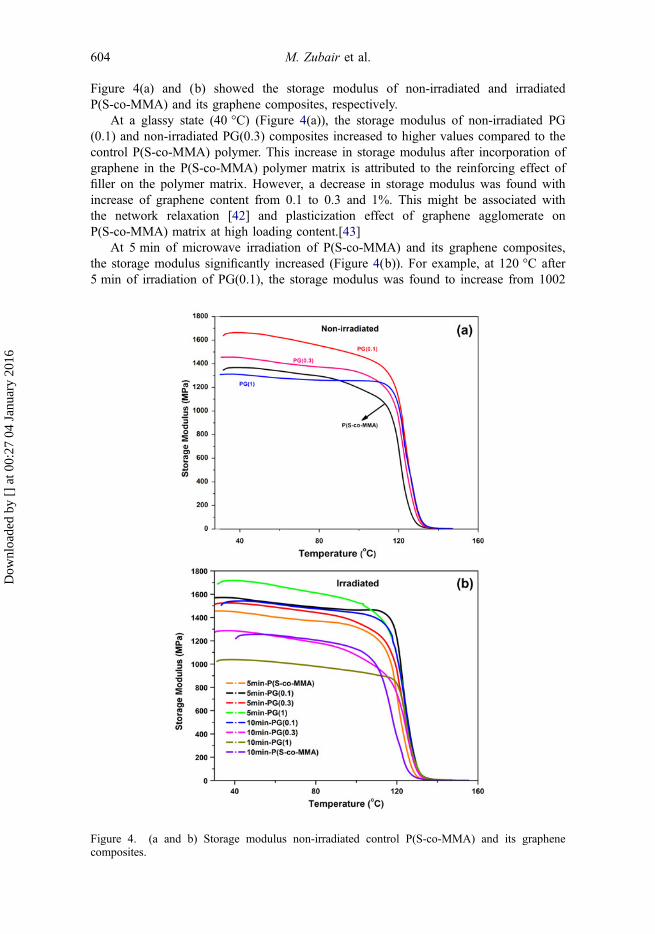
Figure 4(a) and (b) showed the storage modulus of non-irradiated and irradiatedP(S-co-MMA) and its graphene composites, respectively.
At a glassy state (40 °C) (Figure 4(a)), the storage modulus of non-irradiated PG(0.1) and non-irradiated PG(0.3) composites increased to higher values compared to thecontrol P(S-co-MMA) polymer. This increase in storage modulus after incorporation ofgraphene in the P(S-co-MMA) polymer matrix is attributed to the reinforcing effect offiller on the polymer matrix. However, a decrease in storage modulus was found withincrease of graphene content from 0.1 to 0.3 and 1%. This might be associated withthe network relaxation [42] and plasticization effect of graphene agglomerate onP(S-co-MMA) matrix at high loading content.[43]
At 5 min of microwave irradiation of P(S-co-MMA) and its graphene composites,the storage modulus significantly increased (Figure 4(b)). For example, at 120 °C after5 min of irradiation of PG(0.1), the storage modulus was found to increase from 1002
Figure 4. (a and b) Storage modulus non-irradiated control P(S-co-MMA) and its graphenecomposites.
604 M. Zubair et al.
Dow
nloa
ded
by [
] at
00:
27 0
4 Ja
nuar
y 20
16
to 1215 MPa (21% increase compared to non-irradiated PG(0.1). Similarly, in case ofPG(0.3) and PG(1) composites, the storage modulus at 40 °C increased from 1452 to1523 MPa (5% increase) and from 1308 to 1710 (31% increase), respectively, after5 min of irradiation. An increase in storage modulus of control P(S-co-MMA) and itsgraphene composites after 5 min of microwave exposure may have been due to theformation of a cross-linked network and improved polymer–graphene interactioninduced by microwave irradiation. This is due to the formation of free radicals on poly-mer chains as well as the defects produced on the graphene surface,[44] as observed inFTIR and Raman spectra. This produced a stiffer and stronger polymer graphenenanocomposite. Similar results were also found in the irradiation of carbonnanofibers.[45]
However, at a higher irradiation time, i.e. 10 min, the storage modulus of P(S-co-MMA) and its graphene composites started to decrease (11, 6, 11, and 20% decreasefor non-irradiated P(S-co-MMA) and PG(0.1), PG(0.3) and PG(1), respectively). Thisis attributed to the chain scission and photo degradation of the methyl methacrylate inP(S-co-MMA)/graphene composites (confirmed by FTIR spectra). Thus resulted in thereduction in storage modulus of P(S-co-MMA) and its graphene composites.
3.5. DSC analysis
Figure 5(a) shows the glass transition temperature (Tg) of the control P(S-co-MMA)and its non-irradiated graphene composites. Figure 5(b) shows the Tg of irradiatedP(S-co-MMA)/graphene composites. These differential scanning calorimetry (DSC)results are the average of three different runs with an average of ±0.5 °C. It wasobserved in Figure 5(a) that there was an increase of about 2.5 °C of temperature inthe Tg of non-irradiated PG(0.1), PG(0.3), and PG(1) compared to the controlP(S-co-MMA). This indicates that increasing the amount of graphene content on
Figure 5(a). Glass transition observed from DSC for control P(S-co-MMA) and its non-irradiatedgraphene composites.
Composite Interfaces 605
Dow
nloa
ded
by [
] at
00:
27 0
4 Ja
nuar
y 20
16
P(S-co-MMA)/graphene has no prominent effect on the glass transition temperature ofcomposites. After 5 and 10 min of irradiation, no prominent increase or decrease wasobserved in the Tg of all P(S-co-MMA)/graphene composites (Figure 5(b)).
3.6. Electrical conductivity
The electrical conductivity of the P(S-co-MMA)/graphene composites was estimatedusing a four-probe method. The samples PG(0.1)and PG(1) showed conductivities of2.01 × 10−6 and 1.2 × 10⁻⁴ S/cm, respectively, which is much higher than the control P(S-co-MMA) polymer matrix. The conductivity of PG(1) was found to ascend to1.38 × 10−3 S/cm after 5 min of irradiation. This is due to the improved interfacialinteraction of graphene in the P(S-co-MMA) polymer matrix after microwave exposure,and finally, improved electron conduction.
3.7. SEM analysis
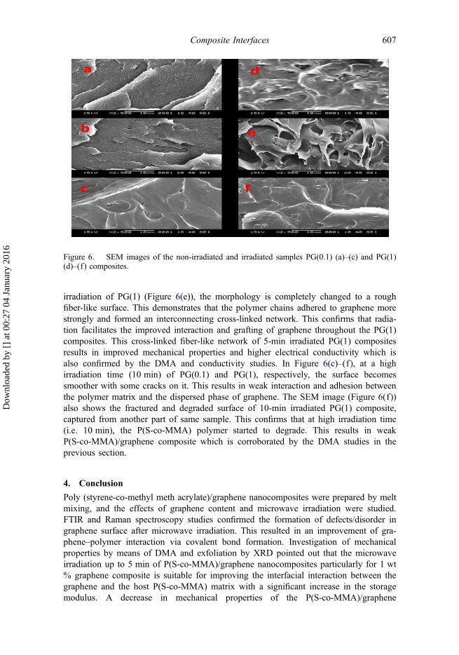
Figure 6(a)–(f) shows the SEM images of the non-irradiated, 5- and 10-min irradiatedsample of PG(0.1) and PG(1), respectively. In Figure 6(a), the SEM image of non-irradiated PG(0.1) shows a smooth discrete surface morphology. This can be attributedto the reinforcement effect of graphene in the PG(0.1) composite. Absence of anyagglomerated graphene particle shows the uniform dispersion of graphene. InFigure 6(b), presence of some fracture and formation of rough surfaces after 5 min ofirradiation of PG(0.1) is due to the encapsulation of polymer matrix onto the graphene.This indicates the enhancement of interfacial interaction between the graphene and thepolymer matrix, which results in a stronger PG(0.1) composite. In contrast, a smoothersurface of non-irradiated PG(1) is seen in Figure 6(d). The presence of voids and asmooth surface shows the formation of graphene agglomerates and weak adhesionbetween the graphene and the P(S-co-MMA) matrix.[46] However, after 5 min of
Figure 5(b). Glass transition observed from DSC of irradiated P(S-co-MMA) and its graphenecomposites.
606 M. Zubair et al.
Dow
nloa
ded
by [
] at
00:
27 0
4 Ja
nuar
y 20
16
irradiation of PG(1) (Figure 6(e)), the morphology is completely changed to a roughfiber-like surface. This demonstrates that the polymer chains adhered to graphene morestrongly and formed an interconnecting cross-linked network. This confirms that radia-tion facilitates the improved interaction and grafting of graphene throughout the PG(1)composites. This cross-linked fiber-like network of 5-min irradiated PG(1) compositesresults in improved mechanical properties and higher electrical conductivity which isalso confirmed by the DMA and conductivity studies. In Figure 6(c)–(f), at a highirradiation time (10 min) of PG(0.1) and PG(1), respectively, the surface becomessmoother with some cracks on it. This results in weak interaction and adhesion betweenthe polymer matrix and the dispersed phase of graphene. The SEM image (Figure 6(f))also shows the fractured and degraded surface of 10-min irradiated PG(1) composite,captured from another part of same sample. This confirms that at high irradiation time(i.e. 10 min), the P(S-co-MMA) polymer started to degrade. This results in weakP(S-co-MMA)/graphene composite which is corroborated by the DMA studies in theprevious section.
4. Conclusion
Poly (styrene-co-methyl meth acrylate)/graphene nanocomposites were prepared by meltmixing, and the effects of graphene content and microwave irradiation were studied.FTIR and Raman spectroscopy studies confirmed the formation of defects/disorder ingraphene surface after microwave irradiation. This resulted in an improvement of gra-phene–polymer interaction via covalent bond formation. Investigation of mechanicalproperties by means of DMA and exfoliation by XRD pointed out that the microwaveirradiation up to 5 min of P(S-co-MMA)/graphene nanocomposites particularly for 1 wt% graphene composite is suitable for improving the interfacial interaction between thegraphene and the host P(S-co-MMA) matrix with a significant increase in the storagemodulus. A decrease in mechanical properties of the P(S-co-MMA)/graphene
Figure 6. SEM images of the non-irradiated and irradiated samples PG(0.1) (a)–(c) and PG(1)(d)–(f) composites.
Composite Interfaces 607
Dow
nloa
ded
by [
] at
00:
27 0
4 Ja
nuar
y 20
16
composites at a higher irradiation time (10 min) is due to the reduction of molecularweight, resulting from the chain scission or photo degradation of the hostP(S-co-MMA) polymer chains. This is also confirmed by the rough damaged surface aswell as appearance of cracks and holes shown by SEM study. The study provides analternative, easy and green method to provide a stronger interfacial interaction betweenthe graphene and the P(S-co-MMA) matrix, which significantly changed the mechanicalproperty of composites.
AcknowledgmentsThe authors would like to thank the Center of Research Excellence in Nanotechnology for thesupport in this study. The corresponding author would like to thank to KFUPM for the supportin establishing the polymer Laboratory at the Chemical Engineering Department, KFUPM.
Disclosure statementNo potential conflict of interest was reported by the authors.
References[1] Si Y, Samulski ET, Hill C, et al. Synthesis of water soluble graphene. Nano Lett.
Lett. 2008;8:3137–3140.[6] Sahoo S, Karthikeyan G, Nayak GC, et al. Modified graphene/polyaniline nanocomposites
for supercapacitor application. Macromol. Res. 2012;20:415–421.[7] Chen Y, Xu Y, Zhao K, et al. Towards flexible all-carbon electronics: Flexible organic field-
effect transistors and inverter circuits using solution-processed all-graphene source/drain/gateelectrodes. Nano Res. 2010;3:714–721.
[8] Wang Z, Zhang H, Li N, et al. Laterally confined graphene nanosheets and graphene/SnO2
composites as high-rate anode materials for lithium-ion batteries. Nano Res. 2010;3:748–756.
[9] Nuvoli D, Alzari V, Sanna R, et al. Synthesis and characterization of graphene-basednanocomposites with potential use for biomedical applications. J. Nanopart. Res.2013;15:1512–1519.
[10] Burdick JA, Anseth KS. Photoencapsulation of osteoblasts in injectable RGD-modified PEGhydrogels for bone tissue engineering. Biomaterials. 2002;23:4315–4323.
[11] George PA, Donose BC, Cooper-White JJ. Self-assembling polystyrene-block-poly(ethyleneoxide) copolymer surface coatings: Resistance to protein and cell adhesion. Biomaterials.2009;30:2449–2456.
[12] Thompson LF, Willson CG. Polymers for microelectronics. In: Thompson LF, Willson CG,Tagawa S, editors. ACS Symp. Washington (DC): American Chemical Society; 1993.p. 305–321.
[13] Kondo Y, Yoshikawa H, Awaga K, et al. Preparation, photocatalytic activities, and dye-sensitized solar-cell performance of submicron-scale TiO2 hollow spheres. Langmuir.2008;24:547–550.
[14] Dresselhaus MS, Dresselhaus G. PA. Synthesis, structure, properties, and applications. Top.Appl. Phys. 2001;80:2–3.
608 M. Zubair et al.
Dow
nloa
ded
by [
] at
00:
27 0
4 Ja
nuar
y 20
16
[15] Kuilla T, Bhadra S, Yao D, et al. Recent advances in graphene based polymer composites.Prog. Polym. Sci. 2010;35:1350–1375.
[16] Zhang Z, Zhang J, Chen P, et al. Enhanced interactions between multi-walled carbonnanotubes and polystyrene induced by melt mixing. Carbon. 2006;44:692–698.
[17] Shen B, Zhai W, Chen C, et al. Melt blending in situ enhances the interaction betweenpolystyrene and graphene through π–π stacking. ACS Appl. Mater. Interfaces. 2011;3:3103–3109.
[18] McIntosh D, Khabashesku VN, Barrera EV. Benzoyl peroxide initiated in situ functionaliza-tion, processing, and mechanical properties of single-walled carbon nanotube-polypropylenecomposite fibers. J. Phys. Chem. C. 2007;111:1592–1600.
[19] Banerjee D, Jha A, Chattopadhyay KK. Synthesis and characterization of water solublefunctionalized amorphous carbon nanotube-poly(vinyl alcohol) composite. Macromol. Res.2012;20:1021–1028.
[20] Feng L, Li W, Ren J, et al. Electrochemically and DNA-triggered cell release from fer-rocene/β-cyclodextrin and aptamer modified dual-functionalized graphene substrate. NanoRes. 2014;1:4–6.
[21] Oh SM, Lee H, Jeong HM, et al. The properties of functionalized graphene sheet/poly(ethylmethacrylate) nanocomposites: The effects of preparation method. Macromol. Res.2011;19:379–384.
[22] Wu G, Tang Y, Weng R. Dispersion of nano-carbon filled polyimide composites using self-degradated low molecular poly(amic acid) as impurity-free dispersant. Polym. Degrad. Stab.2010;95:1449–1455.
[23] Won J, Yoon Y, Kang YS. Changes in facilitated transport behavior of silver polymerelectrolytes by UV irradiation. Macromol. Res. 2013;10:80–84.
[24] Achilias DS. Polymer degradation under microwave irradiation. Adv. Polym. Sci. 2014:1–38.
[25] Teweldebrhan D, Balandin AA. Modification of graphene properties due to electron-beamirradiation. Appl. Phys. Lett. 2009;94:013101.
[26] Rafiemanzelat F, Zonuz AF, Abdollahi E. Fast and eco-friendly synthesis of new hydrolysa-ble and biodegradable copolyurethanes derived from L-leucine cyclodipeptide and differentmolecular weights of PEG in TBAB under microwave irradiation. Macromol. Res.2012;20:902–911.
[27] Cao HL, Wang P, Li Y. Preparation of poly(lactic acid)/Na-montmorillonite nanocompositeby microwave-assisted in-situ melt polycondensation. Macromol. Res. 2010;18:1129–1132.
[28] TK BS, Nair AB, Abraham BT, et al. Microwave exfoliated reduced graphene oxide epoxynanocomposites for high performance applications. Polymer. 2014;55:3614–3627.
[29] Zubair M, Jose J, Emwas AH, et al. Effect of modified graphene and microwave irradiationon the mechanical and thermal properties of poly(styrene-co-methyl methacrylate)/graphenenanocomposites. Surf. Interface Anal. 2014;46:630–639.
[30] Naebe M, Wang J, Amini A, et al. Mechanical property and structure of covalent function-alised graphene/epoxy nanocomposites. Sci. Rep. 2014;4:4375.
[31] Krimm S. Infrared spectra of high polymers. 1960;2:51–172.[32] Suarez JCM, Mano EB, Da Costa Monteiro EE, et al. Influence of γ-irradiation on poly
(methyl methacrylate). J. Appl. Polym. Sci. 2002;85:886–895.[33] Dresselhaus MS, Dresselhaus G, Saito R. Physics of carbon nanotubes. Carbon.
1995;33:883–891.[34] Thomsen C, Reich S. Double resonant Raman scattering in graphite. Phys. Rev. Lett.
2000;85:5214–5217.[35] Ferrari A, Robertson J. Resonant Raman spectroscopy of disordered, amorphous, and
diamond like carbon. Phys. Rev. B. 2001;64:075414.[36] Ferrari AC, Meyer JC, Scardaci V, et al. Raman spectrum of graphene and graphene layers.
Phys. Rev. Lett. 2006;97:187401.[37] Patole AS, Patole SP, Kang H, et al. A facile approach to the fabrication of graphene/poly-
styrene nanocomposite by in situ microemulsion polymerization. J. Colloid Interface Sci.2010;350:530–537.
[38] Patole AS, Patole SP, Jung SY, et al. Self assembled graphene/carbon nanotube/polystyrenehybrid nanocomposite by in situ microemulsion polymerization. Eur. Polym. J.2012;48:252–259.
Composite Interfaces 609
Dow
nloa
ded
by [
] at
00:
27 0
4 Ja
nuar
y 20
16
[39] Hu H, Wang X, Wang J, et al. Preparation and properties of graphene nanosheets–polystyrene nanocomposites via in situ emulsion polymerization. Chem. Phys. Lett.2010;484:247–253.
[40] Liang J, Huang Y, Zhang L, et al. Molecular-level dispersion of graphene into poly(vinylalcohol) and effective reinforcement of their nanocomposites. Adv. Funct. Mater.2009;19:2297–2302.
[41] Du X, Yu Z, Dasari A, et al. New method to prepare graphite nanocomposites. Chem.Mater. 2008;20:2066–2068.
[42] Tang J, Zhou H, Liang Y, et al. Properties of graphene oxide/epoxy resin composites.2014;2014:1–5.
[43] Saladino ML, Motaung TE, Luyt AS, et al. The effect of silica nanoparticles on themorphology, mechanical properties and thermal degradation kinetics of PMMA. Polym.Degrad. Stab. 2012;97:2477.
[44] Compagnini G, Giannazzo F, Sonde S, et al. Ion irradiation and defect formation in singlelayer graphene. Carbon. 2009;47:3201–3207.
[45] Evora MC, Klosterman D, Lafdi K, et al. Functionalization of carbon nanofibers throughelectron beam irradiation. Carbon. 2010;48:2037–2046.
[46] Wang N, Gao N, Fang Q, et al. Compatibilizing effect of mesoporous fillers on themechanical properties and morphology of polypropylene and polystyrene blend. Mater. Des.2011;32:1222–1228.