FHWA-NJ-2019-004 Evaluation of Precast Concrete Pavement Systems and Cast-In-Place, Phase I: Identification of Accelerated Concrete Pavement Rehabilitation Methods FINAL REPORT June 2019 Submitted by: Yusuf Mehta, Ph.D., P.E. (PI) Professor & Director Department of Civil and Environmental Engineering & Center for Research and Education in Advanced Transportation Engineering Systems (CREATEs) at Rowan University Ayman Ali, Ph.D. (Co-PI) Manager Center for Research and Education in Advanced Transportation Engineering Systems (CREATEs) at Rowan University Daniel Offenbacker Graduate Research Assistant Rowan University NJDOT Research Project Manager Ms. Kimbrali L. Davis In cooperation with New Jersey Department of Transportation Bureau of Research And U. S. Department of Transportation Federal Highway Administration
Transcript
FHWA-NJ-2019-004
Evaluation of Precast Concrete Pavement Systems and Cast-In-Place,
Phase I: Identification of Accelerated Concrete Pavement Rehabilitation Methods
FINAL REPORT
June 2019
Submitted by:
Yusuf Mehta, Ph.D., P.E. (PI)
Professor & Director
Department of Civil and Environmental
Engineering & Center for Research and
Education in Advanced Transportation
Engineering Systems (CREATEs)
at Rowan University
Ayman Ali, Ph.D. (Co-PI)
Manager
Center for Research and Education in
Advanced Transportation Engineering
Systems (CREATEs) at Rowan
University
Daniel Offenbacker
Graduate Research Assistant
Rowan University
NJDOT Research Project Manager
Ms. Kimbrali L. Davis
In cooperation with
New Jersey
Department of Transportation
Bureau of Research
And
U. S. Department of Transportation
Federal Highway Administration
ii
DISCLAIMER STATEMENT
The contents of this report reflect the views of the author(s) who is (are) responsible for the facts and the accuracy of the data presented herein. The contents do not necessarily reflect the official views or policies of the New Jersey Department of Transportation. This report does not constitute a standard, specification, or regulation.
Table 19: Cast In-Place Mixtures Recommended for Further Evaluation ...................... 77
1
EXECUTIVE SUMMARY Concrete pavements (PCC pavements) play a crucial role in highway infrastructure, primarily in regions such as New Jersey (NJ) which has high traffic density. Due to heavy traffic over several years these pavements are deteriorating and in need of repair. Typical full-depth concrete pavement repairs result in long closure times due to concrete placement, texturing, and curing. These closures result in high traffic congestion and driver discomfort. In an effort to alleviate these issues, technologies have been developed for the purpose of rapid concrete pavement repair. These include Precast Concrete Pavement (PCP) systems and quick setting Cast-In-Place (CIP) materials. These technologies have shown success in shortening roadway closure times, as well as, remaining structurally intact. For example, the New Jersey Department of Transportation (NJDOT) has adopted the PCP system developed by The Fort Miller Company Inc. for rapid full-depth concrete pavement rehabilitation. This PCP system can be installed overnight; allowing for free traffic flow during rush hour the following morning. Thus far, NJDOT has noted the success of using PCP and has observed that no pavement damage has occurred. Though this system has shown success, alternative PCP systems have been developed and are currently reported to perform well in other states. New Jersey also has an approved set of CIP repair materials for partial and full depth repairs. This study was initiated with the goal of identifying accelerated concrete pavement repair methods/technologies (both PCP and CIP) for use in full-depth rehabilitation of concrete pavements in NJ. To fulfill this objective, the first phase of this study (Phase I) focused on documenting the current state of practice through conducting a comprehensive literature review pertaining to available concrete pavement rapid repair technologies. Several PCP systems (both proprietary and non-proprietary) were identified for the potential use in NJ. These systems include: The Fort Miller Company Inc., Jersey Precast, Roman Stone, Illinois Tollway Method, Caltrans Rapid Roadway, and more. Additionally, CIP technologies were discovered for the potential use in NJ. The review of CIP technologies provided information regarding the modifications to the concrete mix, strength attainments at different times, and mix setting times. Phone interviews of Subject Matter Experts (SMEs) from State Departments of Transportation (DOTs) were conducted to gain a better understanding of what DOTs observed when using PCC pavement rapid repair technologies. Their recommendations and current specifications for working with rapid concrete pavement materials were also obtained. Specifically, the interviews provided insight towards the approval process of PCP systems, PCP installation procedures that were successful, and overall performance of PCP systems. From the interviews, there was consensus that the PCP technologies should be approved and evaluated using performance-based specifications due to the high variability between PCP systems. The interviews also gave a better understanding of the development and use of non-proprietary systems. Based on the information gathered in the literature review and from discussions with SMEs, a draft PCP system approval process and usage specifications were developed.
2
As part of Phase I, it was also discovered that concrete mixtures for rapid repair of PCC pavements can be classified into two types: 1) Class V concrete for full depth rapid repair, and 2) quick setting bagged, pre-prepared, manufactured cementitious mixtures for partial depth concrete pavement repair. Class V concrete literatures were obtained from journal publications and research reports. A survey was conducted with 18 DOT agencies and a list of 218 quick-setting patch materials were compiled. From the list, the products most widely approved by various DOTs, including NJDOT, and common or emerging technologies were reviewed in detail. The review included mixture preparation, application, and strength and durability characteristics. The information obtained for the CIP mixtures were then compared with the NJDOT requirements for Portland concrete pavement repair. Based on the efforts of this study, the following conclusions were be drawn:
Several precast concrete pavement systems could potentially be used in NJ pending system approval by NJDOT. These include systems used in neighboring states along with those implementing non-proprietary components commonly used in other regions.
The use of leveling bolts for PCP panel installation is often the preferred method for slab installation and leveling as that speeds up the process.
The main reason for PCP failure is due to poor slab installation, thus greater oversight and quality control are necessary during installation.
Most DOTs that use rapid PCP repairs allow for the acceptance of new PCP technologies through a trial installation procedure. In this, the contractor and system must demonstrate the ability to install precast concrete pavement panels according to the DOT’s specification and obtain an adequate Load Transfer Efficiency (LTE). This has been implemented in the recommended draft system approval process and specifications.
Rapid full depth repair is an important component in pavement restoration and rehabilitation. The mixtures for this are Class V concrete. From the conducted literature review, it was found the current mixtures barely meet the 6.5hr flexural strength requirement for Class V concrete.
An extensive list of approved Types 1A and 1B quick setting patch materials is maintained by NJDOT in their Qualified Materials Database, available on NJDOT’s website. From the review of the list, modification of quick setting patch materials with polyester-polymer and blending of Type I cement with calcium aluminate cement has not been studied; warranting the need for further evaluation.
3
INTRODUCTION Background The New Jersey Department of Transportation (NJDOT) is responsible for maintaining over 8,000 lane miles of highway pavements (NJDOT, 2015). Using an accelerated PCC pavement rehabilitation system, the NJDOT has the ability to rehabilitate and open PCC pavements to traffic within a short period of time. This is the case because these technologies can be completed within overnight (8 to 10 hour time window) depending on the amount of repair needed. An example of an accelerated full-depth concrete rehabilitation technology that NJDOT has approved and employed is the Super-Slab precast system developed by the Fort Miller Company, Inc., located in Schuylerville, New York. To approve the use of the Super-Slab system in New Jersey (NJ), the NJDOT relied on Heavy Vehicle Simulator (HVS) testing conducted at the University of California at Davis (UC Davis) (Kohler et al., 2007) and experiences reported in other locations. The researchers at UC Davis evaluated the Super-Slab precast system using two full-scale pavement sections subjected to accelerated loading and damage using the HVS. NJDOT has been using the Super-Slab precast system since 2008. There are additional precast systems used for pavement repair throughout the United States that are not currently approved for use in New Jersey. In addition to precast systems, there are rapid concrete repair Cast-In-Place (CIP) materials—rapid set cement, Rapid Mortar 10-60, rapid set cement with latex modifier, etc.—that are approved for use as a partial-depth repair or patching material in NJ. These materials have potential to transition to a full-depth repair material; limited research was conducted to investigate these materials. It is therefore necessary to investigate the current systems and materials, as well as new materials/technologies, for accelerated PCC rehabilitation in NJ. Although the approved sets of materials have provided satisfactory performance for their intended uses, the addition of more PCC rapid repair technologies could lead to shorter repair times, greater cost-efficiency, and reduction in traffic congestion. Thus, it is crucial to identify and evaluate rapid PCC pavement rehabilitation technologies. Phase I of this study aims to address these needs by identifying other PCC and CIP rapid repair technologies that can potentially be employed in NJ. Goal and Objectives The goal of this project was to evaluate current accelerated concrete pavement rehabilitation technologies for use in NJ. The specific objectives of Phase I of this project included:
Review available literature on precast concrete pavement (PCP) systems used for repairs. This review includes proprietary and non-proprietary systems, the variations in construction practices between systems, and any current standards and specifications for construction and installation. Additionally, an overview of the performance of each system and the limitations/difficulties of each system was included in the review.
4
Review available literature on CIP pavement systems. This review included established accelerated concrete pavement rehabilitation systems, concrete patching materials, modified concrete mixes, and other concrete mixes. Additionally, this review included an overview of the performance of each system and the limitations/difficulties included with each system.
Evaluate the construction criteria and past performance of full-depth accelerated cast-in-place concrete rehabilitation systems.
Contact State Highway Agencies (SHAs) that have implemented PCP systems for past construction/performance observations and recommendations.
Draft a preliminary specification for accelerated concrete pavement rehabilitation systems constructed and installed in NJ based on experiences of other SHAs.
Report Organization This report is organized into four chapters. The first chapter presents the background, problem statement, objectives, and outline of the report. Chapter two presents a comprehensive literature review summarizing the current state-of-the art on the PCP and CIP systems. Chapter three includes a description of the practices, observations, and recommendations from SHAs that have adopted several practices. Chapter four presents the conclusions and recommendations for future study and implementation.
5
LITERATURE REVIEW The literature review consisted of a comprehensive evaluation of the available accelerated PCC and CIP rehabilitation systems. This review is presented in two sections—PCP and CIP—for simplicity. Each section includes respective construction and installation procedures, performance evaluation, technical information, and recommendations/limitations. This review also indicates which systems are no longer in use in the United States (US) and systems that have been modified. Precast Concrete Pavement (PCP) Figure 1 presents the states in the U.S. that have been using PCP systems or are considering implementing a system of their own. Figure 1 indicates that PCP systems are mostly being used in states like NJ, New York, California, and Utah. Additionally, some states are developing/adopting their own systems (non-proprietary) to reduce costs. These states include Illinois, Iowa, Michigan, California, and Texas. Hawaii was in the process of developing a precast system, but decided to implement the California Rapid Roadway system. New Mexico and Washington have upcoming implementation planned.
Figure 1: Map of US states that routinely use, have implemented, or are developing their own PCP system (Tayabji and Buch, 2013).
Table 1: Type of PCP systems being used in the United States
State Proprietary Nonproprietary Notes
California Fort Miller Rapid Roadway PCP -
Colorado Stitch-in-Time - No longer marketed
Hawaii Rapid
Roadway, Kwik Slab
- -
Illinois Fort Miller Illinois PCP (2015) -
Iowa - Iowa PCP (2008) -
Michigan - Michigan PCP (2003) No longer used
New York Fort Miller Roman Road -
Texas Fort Miller Texas PCP (2015) -
Utah Fort Miller Utah PCP (2011)
Utah’s System no longer used
(have open specification
instead)
7
Table 2: Number of PCP installation in the United States (NPCA, 2018) Precaster CA CO HI IA IL MI MN NJ NV NY ON PA QC UT VA VT Total
Fort Miller 14 23 1 1 1 40
Roman Stone
8 8
Unknown 5 1 1 3 1 1 1 3 1 1 2 20
Jensen 1 1
Mountain West
10 10
ProCast 19 19
CB Concrete
1 1
ConFab 2 2
Armtec 1 1
Oldcastle 1 1
GPRM Prestress
LLC 1 1
Hawaiian Dredging
1 1
Grand Total 28 1 2 1 3 1 1 14 1 32 4 1 1 11 3 1 105
8
Table 3: States with over one lane-mile of installed PCP (NPCA, 2018).
State Total Lane-Miles
California 51.69
Hawaii 3.57
Illinois 7.36
Indiana 1.73
New Jersey 7.06
New York 28.03
Utah 3.24
Wisconsin 1.60
Ontario 3.22
Site Preparation and Considerations for Precast Repairs The primary criteria that govern the use of PCP systems include the need for short work windows (typically overnight) due to high traffic volumes and the desire for a durable, high-quality product in the area to be repaired. However, there are several factors that potentially impact the decision process or the design, fabrication and installation of the precast panels. These factors include but are not limited to: available work space; vertical clearance (restrictions) at the project site; access issues for large or heavy equipment and panel haul trucks; availability of certified, qualified, and properly equipped precast concrete plants; existing condition of pavement (including the nature, extent, and severity of distresses present); accommodation of existing utilities; and pavement geometry and planning requirements. To better understand these factors, the generic procedure for installing slabs in the Illinois tollway system is explained below. Note that these general processes remain the same for other precast systems (proprietary and non-proprietary) as well. These procedures are routinely followed for precast system installation. However, certain aspects of these operations are unique to jointed precast concrete pavement installation. Therefore, the procedures must be fully understood by contractors and inspection personnel for successful installation of the precast panels. The primary concerns during site investigation are listed below and described in the following subsections:
- Maintenance and protection of traffic and protection of job-site personnel; - Establishment of safe and efficient work areas; - Surveying (saw cut and panel layout); - Saw cutting; - Removal of existing pavement; - Subbase repair; and - Subbase preparation.
9
Maintenance and traffic operation PCP systems are installed with the highest installation rates when an adjacent lane is available for delivering the precast panels to the work site and for the panel lift equipment. In this manner, a single-lane repair requires a minimum two-lane closure (or one lane plus a shoulder), three lanes (or two lanes and an adjacent shoulder) are required for placing repairs in two lanes, etc. Figure 2a shows the installation of precast panels using one outside lane and an existing 10-foot shoulder. Split-traffic configurations may be necessary for maintaining adequate traffic flow when repairing the interior lanes. Precast panels can also be installed using a single-lane closure and some traffic management of at least one adjacent lane. Delivery trucks approach the installation site with traffic in the adjacent lane. Upon reaching the off-loading site, the truck stops just long enough for the crane, which is set up in the working lane, to remove the panel. The crane lifts the panel from the delivery truck and installs the panel in the prepared area. If the area has been prepared correctly for full grade support, the crane can move forward over the panel that was just placed to the proper location for setting the next panel. This single-lane closure installation process is displayed in Figure 2.
(a) (b)
Figure 2: (a) Single lane repair using an existing lane and the shoulder, and (b) single lane closure and placement of slabs using crane (SHRP-2, 2015)
Equipment The project site must be accessible for heavy construction equipment that is necessary for removing the existing pavement and installing new PCP panels. Site access is usually not an issue on most major highways and truck routes; urban applications may require special evaluation of the strength and thickness of the existing mainline and/or shoulder pavement to determine if it is adequate for handling heavy construction equipment and highway truck loads. In some cases, shoulders may need to be replaced with thicker pavement before the project begins to handle temporarily-diverted traffic. Consideration should also be given to pavement adequacy as it may relate to possible damage to underlying utilities and associated structures. The size of equipment typically varies with the sizes of the panels being placed. Larger panels require larger equipment
10
(often cranes). Figure 3 shows the crane width necessary for a certain Virginia DOT PCP project. It may be beneficial for the designer to give the contractor panel size options (within specified limits) so that the contractor can minimize overall installation costs. The existing pavement being replaced can be cut or broken into smaller pieces so that removal can be performed with the same equipment used for installation (allowing for smaller equipment to be used, such as an excavator instead of a crane). Additionally, contractors frequently offer lower installation prices if the same equipment can be used to remove existing pavement and place new panels (NPCA, 2017), so an attempt to implement this method should be made. For this project, all panels can be placed and potentially excavated (as long as no significant structural damage occurs) using a crane.
Figure 3: Typical width taken up by crane for placement of larger panels (NCPA, 2017)
Another example of equipment that can be used to install panels is a fork truck. A fork truck is generally used when installing panels in places that a crane cannot reach, such as under an overpass, as seen in Figure 4.
Establishment of safe and efficient work areas Precast paving work is dangerous because workers are often required to operate near live traffic every night. In this work, portable traffic control devices such as signs, arrow boards, bumper trucks, and traffic cones are typically installed at the beginning of each work shift, before the more protective continuous concrete barriers, to separate/direct traffic and protect job site workers. Though there is often pressure to install these devices quickly to allow workers as much time as possible to complete their work, special care should be taken to ensure they are installed strictly in accordance with the requirements shown in the contract plans and the approved traffic control plan. The consideration for multi-lane work areas are:
At least two full lanes: one lane for excavation and placement equipment, one lane for removal and delivery trucks;
At least one partial “buffer” lane for traffic-directing devices and additional worker safety. Some states, such as California, require a full lane as a safety buffer zone. The partial buffer lane can potentially be less than 6 feet wide, increasing the need for additional precautions such as safety spotters and traffic control officers. The main responsibility of safety spotters and traffic control officers is to monitor workers and ensure they remain within safe working zones; and
Familiarity of the contractor with the schedule of available lane closures.
Surveying For all precast systems, a survey is typically required to gather field data from the existing roadway before shop drawings can be prepared. A pre-shop drawing survey of the existing roadway is recommended to ensure that panels are designed to fit between existing longitudinal joints and on horizontal curves such that the specified maximum longitudinal and transverse joint widths are not exceeded. After that, a second survey is required just prior to saw cutting the existing pavement for removal. This survey typically includes the layout of the transverse saw cuts at the beginning and end of each repair section. No matter how the contractor plans to install the panels, the surveyor should be aware that actual panel dimensions vary from nominal dimensions shown on the shop drawings, as allowed by specified fabrication tolerance. These variations must be considered when laying out intermediate and end transverse saw cuts. To determine the length “L” between ends of saw cuts for multiple panel placement, Equation 1 is used. The lay length can be quantitatively defined according to Equation 1 and as shown for the two panels presented in Figure 5. “Theoretical Lay Length” = Nominal Panel Length + Fabrication Tolerance (1)
12
Figure 5: Schematic for determining lay length (NPCA, 2017).
Saw cutting If the existing longitudinal joint is to be retained (as in most cases), it is necessary to saw along the existing joint to sever the existing tie bars. In some cases, the true location of these joints is readily visible. In other cases, however, the center of the visible joint seal in existing longitudinal joints may not coincide with the actual center of the longitudinal joint. In these cases, the joint seal can be removed entirely to expose the joint. Saw operators should be trained on the importance of following layout lines because—unlike saw cutting for fast-track cast-in-place pavement, where plastic concrete conforms to any saw cut, even if not straight—precast panels require precise saw cuts to ensure the maximum specified joint widths are not exceeded. Additionally, workers must understand that saw cuts resulting in too narrow openings for the new panels result in costly delays, while saw cuts that result in excessive joint widths may be cause for panel rejection. With regard to the preferable and/or adverse weather for saw cutting, transverse saw cuts during the summer months can be problematic because pavement expands during periods of rising temperatures. Expansive forces can be so great that saw blades bind up during the sawing operation. This can be avoided by making full-depth cuts at night, when temperatures and expansion forces are lower.
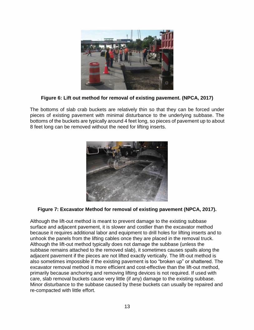
Removal of Existing Pavement The removal operation is key to maximizing installation rates because it is the first operation each night. Existing pavement is typically removed by using either the lift-out or excavator methods. The lift-out method consists of drilling holes in sawed pieces of the pavement to accommodate lifting inserts that are mechanically or chemically anchored in place. At the time of removal, lifting cables are attached to the inserts so that a crane or excavator can remove the pavement and place it in a haul truck (Figure 6). Cables are then unhooked and lifting devices are removed so they can be used again. The excavator method involves the removal of existing pavement panels using an excavator and what is commonly called a “slab crab” bucket. The bucket is built with a notch so that pieces of the existing pavement can be wedged in the notch for lifting and removal, as seen in Figure 7.
13
Figure 6: Lift out method for removal of existing pavement. (NPCA, 2017) The bottoms of slab crab buckets are relatively thin so that they can be forced under pieces of existing pavement with minimal disturbance to the underlying subbase. The bottoms of the buckets are typically around 4 feet long, so pieces of pavement up to about 8 feet long can be removed without the need for lifting inserts.
Figure 7: Excavator Method for removal of existing pavement (NPCA, 2017).
Although the lift-out method is meant to prevent damage to the existing subbase surface and adjacent pavement, it is slower and costlier than the excavator method because it requires additional labor and equipment to drill holes for lifting inserts and to unhook the panels from the lifting cables once they are placed in the removal truck. Although the lift-out method typically does not damage the subbase (unless the subbase remains attached to the removed slab), it sometimes causes spalls along the adjacent pavement if the pieces are not lifted exactly vertically. The lift-out method is also sometimes impossible if the existing pavement is too “broken up” or shattered. The excavator removal method is more efficient and cost-effective than the lift-out method, primarily because anchoring and removing lifting devices is not required. If used with care, slab removal buckets cause very little (if any) damage to the existing subbase. Minor disturbance to the subbase caused by these buckets can usually be repaired and re-compacted with little effort.
14
Sub-base Preparation for PCP Installation PCP panels are typically placed on some type of aggregate base; however, cement-treated bases (CTB) are used in some states and provinces, particularly in California. Placement of PCP panels on existing CTB can be problematic if workers cannot determine where the top of the material lies relative to the planned elevations and profile of the bottoms of the PCP panels. In theory, the subbase profile can be determined by taking cores through the existing pavement, but this practice is not always reliable because the height of the CTB and the thickness of the existing pavement may vary significantly (due to construction variability and diamond-grinding operations) over the length of the repair. If the existing CTB is to be retained, it also needs to be considered that some of it may need to be removed to accommodate the new PCP panels. If only isolated high spots of existing CTB are encountered in intermittent repair areas, they may be removed by scraping with the excavator bucket. However, this is a slow and potentially costly process. When larger areas need to be removed, it is more practical to use a skid-steer-mounted milling head (Figure 8). Trimming the CTB using either of these methods is a time-consuming and costly process that should be considered carefully during the design phase of the project.
Figure 8: A skid-steer mounted milling head used to trim a cement treated base (NCPA, 2017)
Placement of new panels on existing or new drainable base material is generally not recommended because unbound bedding material placed between the base and the new panels will wash into voids in the drainable base unless measures are taken to prevent it. One measure is to use cement-treated bedding material (CTBM) instead of unbound concrete sand on top of the drainable base. The benefit of using CTBM as a bedding material is that it turns into a lean concrete layer that will not wash through the drainable base. CTBM also prevents fluid bedding grout from filling voids in the drainable base below.
General Precast Installation Considerations Precast concrete pavement systems, whether proprietary or open specification, have many common features such as the typical requirements for concrete strength and
15
durability properties, general location of lifting screws and grout ports, and the internal reinforcing systems. Where the systems tend to differ is in relation to the support conditions and jointing and load transfer systems. Once installed the systems behave similar to conventional concrete pavements (Tayabji, 2016a).
Support Options Panels are either grade supported or supported on a thicker grout or urethane layer. The methods are illustrated in Figure 9. In a grade supported system the panel is placed upon a prepared bedding layer which is either a cemented granular bedding, a graded layer of bedding sand, or no bedding in the rare case in which the bedding can be finished or graded and compacted well. Once the panel is set on the prepared bedding or base layer the panel is undersealed with a low-viscosity, high-strength material such as a rapid-setting grout. Grade supported systems can be opened to short-term traffic which allows the construction to proceed in short construction windows. A disadvantage is the time required for precise grading of the subbase and bedding material (NPCA, 2017). For a grout or urethane supported system the panel is typically constructed one-half to one inch thinner than the existing pavement. Alternatively, the finished grade is left slightly low and a full thickness panel is used. The panel is set to match finished elevation using shims or removable leveling screws. Once the slab is leveled with the shims or screws, a grout is injected through ports to fill the void below the slab. Slab-jacking techniques using grout or urethane can also be alternatively used to lift the slab to final elevation. Grout or urethane supported systems usually have higher precast installation rates; however, grout or urethane require one to three hours curing time before opening to traffic (NPCA, 2017). California no longer allows the use of shims because of the concentrated point load below the slab1.
(a) (b)
Figure 9: Precast panel support methods. (From Tayabji, 2016a).
1 Phone conversation with Deborah Wong, P.E., Deputy District 7 Director, Caltrans, Division of Maintenance, Los Angeles and Ventura County, 7/18/2018.
16
Load transfer systems Tayabji and Brink (2015) provided a summary of the currently used load transfer systems in an FHWA Tech Brief FHWA-HIF-16-08. The load transfer provisions are similar to the methods used in dowel bar retrofit. Slots are provided on one or both sides of the joint and are located at the top or bottom of the panel. The slots are usually narrow mouth and are open for the full or a partial length of the dowel. Bottom-Slot Dowels – This load transfer system incorporates dowel slots at the bottom of the slab. In a repair situation, dowel holes are drilled into the existing pavement and the dowel bars are epoxied into the holes. The repair panel is then lifted into place over the dowels and a flowable grout is used to fill the dowel slot. The bottom panel dowel slots are shown in Figure 10. This is a patented process and cannot be implemented without the consent of the proprietor (Fort Miller Inc.).
Figure 10: Fort Miller bottom-slot dowel system.
Narrow-mouth dowel systems – Narrow-mouth dowel systems were developed as part of the Strategic Highway Research Program 2, Project R05 as an alternative to a full dowel bar retrofit that requires slots on both sides of the joint. At the surface, the slots are about 1 inch wide and spread to about 3 inches wide and within an inch below the panel mid-height. The narrow width at the surface allows for temporary traffic prior to grouting the dowels. With this type of dowel system, the dowel bars are placed in the 14 to 16-inch-long slot. Once the panel is positioned, the dowel is slid into predrilled holes in the adjoining panel. Figure 11 shows the standard SHRP2 dowel system. Figure 12 shows a modification developed by the Illinois Tollway that includes a widened section near the joint that allows for sliding and rotating the dowel by hand and improving epoxy adhesion to the bar. Caltrans has a generic version of the system in which a teardrop shape is used rather than the triangular shape of the SHRP or Illinois Tollway versions (Figure 13). The Barra Glide dowel from the Rapid Roadways System is a modification with only a partially open narrow slot (Figure 14). The Jersey Precast and Roman Road (Figure 15) systems also have variations of the narrow-mouth slot.
17
Figure 11: SHRP2 standard narrow-mouth dowel system (from Tayabji and Brink, 2015).
Figure 12: Illinois Tollway modification to SHRP narrow-mouth system (from Tayabji and Brink, 2015).
Figure 13: Caltrans standard teardrop-shaped narrow-mouth system (from Tayabji and Brink, 2015).
18
Figure 14: Rapid Roadways Barra Glide dowel system (from www.rapidroadway.com/Gallery).
Wide-mouth systems – Wide-mouth systems have been used but are no longer as common because they require patching during the same lane closure. The slots are too wide to allow traffic without patching. Other recommendations included in FHWA-HIF-16-008 (Tayabji and Brink, 2015) include:
Dowels should not be placed more than 12-inches from the outside corner of the panel.
A dowel diameter of 1.25-inches is recommended for slabs 10-inch or less and a 1.5-inch dowel is recommended for slabs between 10- and 14-inches thick.
A 15-inch length dowel is adequate rather than the standard 18-inch dowel length used in the U.S.
Dowels are spaced at 12-inches and only a cluster of four is required at each wheel-path. Dowels are not required in the middle of the joint.
Dowel bar patching grout needs to develop 2000 to 3000 psi strength within 4 hours of installation and prior to opening the road to traffic.
Available Precast Rapid Repair Systems Accelerated concrete pavement rehabilitation using precast panels have many installation features/properties to consider as presented in the previous section. This is because many factors can affect the structural and functional life of this type of pavement. As a result, unique PCP systems have been developed by different companies (proprietary) and governmental agencies (non-proprietary) in various regions of the U.S. with different installation procedures. A description of the most common precast systems in the U.S. are presented in the following subsections.
Fort Miller Super-Slab System The Fort Miller Super-Slab technology is a proprietary bottom-slot joint system (shown in Figure 10), where the slabs are precast offsite using "High-Strength" concrete (Moellman, 2013) with a small amount of reinforcement embedded for shipping and handling. It is the most widely/successfully used system in the U.S. It has been used for over 36 lane miles of highway so far. It is the only system that uses bottom-slotted dowel bars (NPCA, 2017). These load transfer dowels are embedded in the slab in the transverse joints with the potential of using tie bars longitudinally. A typical bottom
slotted joint used in Fort Miller Super-Slab system is shown in Figure 10. The dowels can be either epoxy-coated steel or fiber reinforced polymer dowels (Tayabji et al., 2013). The Super-Slab method utilizes dovetail slots for the dowels to minimize the amount of dowel movement and slippage within the panel. The precast slabs are made in a straight or, in the case of Fort Miller’s proprietary system, warped pattern depending on the subgrade condition of pavement in need of repair. Fort Miller utilizes both grade-supported and grout supported systems. Grade supported systems provide a precisely graded foundation that allows panel placement to the proper elevation with reasonably complete support. Thus, it allows immediate opening to short-term traffic; and offers a more effective use of short construction windows because installation activities do not need to be stopped to let bedding grout harden before opening to traffic (NPCA, 2017). The task of grout-supporting is typically conducted by the use of shims or leveling screws to allow grout to flow in through distribution channels (maintained by a gasket along the perimeter). The construction process of the Fort Miller Super Slab system begins with the cutting of the failed piece(s) of pavement using a diamond bladed saw, then lifting out with a crane (typically truck mounted). The subgrade is prepared with a thin layer of stone sand and is then graded, compacted, and graded one final time. Once the subgrade is compacted, the precast panel is lifted and placed onto the subgrade. Next, the dowels are inserted into the existing pavement. HD-50 dowel grout is used to solidify the dowels into place. The bedding grout is distinct from the dowel grout, and is applied after the dowels are anchored. The bedding grout is normally applied in the subsequent days after installation. Using this system, as long as the subbase is properly leveled and compacted, the pavement can be opened to traffic immediately after installation without the grout (Moellman, 2013). Tayabji, et al. (2009) provide some history of the implementation of the Super Slab system including its introduction into New Jersey. One of the earliest uses of the Fort Miller Super Slab system was by the New York State DOT (NYSDOT) and the New York State Thruway Authority (NYSTA). The first major use was in 2001 at the Tappan Zee Toll Plaza in 2001. The system was also used in by the Port Authority of New York and New Jersey (PANY/NJ) in July of 2003 to replace approach slabs to the Lincoln Tunnel. In 2005, NYSDOT developed documents to ensure product quality following some early issues in Super Slab installations. The documents included:
1. Precast Pavement Design Guidelines: a. Candidate project selection criteria.
2. Precast Pavement Material specifications:
a. Fabrication Standard Drawings. b. Fabrication Working Drawings for projects. c. Manufacturer’s Installation Instructions:
i. Subbase preparation. ii. Slab panel installation. iii. Leveling of slab panels.
20
iv. Backfilling grout—use and strength gain. d. Trial installation (test section).
3. Precast Pavement Construction Specifications: a. Joint layout plan by contractor. b. Slab panel installation process. c. Surface tolerances. d. Opening to traffic requirements.
In 2006, CALTRANS performed accelerated pavement testing of a Super Slab installation using a heavy vehicle simulator at University of California – Davis (Kohler, 2007). The first use of the Super Slab system by NJDOT occurred during 2007–2008 for repairs along a section of I-295 in Burlington County. This first project was originally bid as a cast-in-place, full-depth repair project. Concerns with construction traffic management led to the conversion of the project to the use of precast panels.
Roman Stone System The Roman Road system is a non-proprietary jointed precast PCP system developed by the Roman Stone Construction Company, located in Bay Shore Long Island, New York. Roman Stone has developed specifications and installation procedures for this precast pavement repair system that was developed as an improvement to the Michigan system (discussed below). They have trademarked the name of the system as Roman Road but none of the components are patented. The system can be used for intermittent or continuous repairs and is not considered proprietary. When installed with a polyurethane lifting and leveling system, Roman Stone works exclusively with a formulation produced by Uretek, based on past positive experiences with this particular material and company. The unique feature of this system is the use of a high density polyurethane (HDP) foam as a bedding material for the pavement rather than grout, natural aggregate, or aCTB. The polyurethane injection procedure allows for the slabs to be placed and set to grade all in one shift. It also requires little to almost no subgrade preparation, and the slab arrives on site with factory-drilled injection ports already embedded to provide a path for the polyurethane (NPCA, 2017). In the Roman Road system, dowels are predrilled into the adjacent pavement panel which could be existing cast in place pavement or another precast panel. Dowel pockets are cast into the repair slab and the cover over these pockets is broken out at the time load transfer dowels are placed. The dowels are fitted into the preformed slots and then epoxied into the predrilled holes on the adjacent panel. The dowels are then grouted in place. This dowel installation method replaces a previously used system where the new slab is set into place, and then slots are cut in the new slab and the existing pavement for the load transfer dowels. Typically an epoxy-coated, circular steel dowel is used. Sandblasting is used to create clean slots for a good bond with the dowels. Further, these panels can be installed at any temperature (3–105oF) and can be reopened to traffic in just minutes after complete installation since polyurethane is a two-part polymer that hardens and reaches working strength in 15 minutes (NPCA, 2017). Another benefit of using polyurethane foam is that it works very well in compression; the greater the pressure required to lift the slab, the greater the final polymer compression strength will be
21
(NPCA, 2017). Road projects typically use a 6 lb./in3 (0.2 kg/cm3) high-density mixture. The polymer is also weather-resistant to cold and environmentally inert. As the mixture expands, it typically spreads out 3 feet (1 m) in diameter, filling in voids and displacing under-pavement water in the process (NPCA, 2017).
The panels can be of varying lengths while the width is typically kept constant at 12 ft.
The thickness of the panel is designed to be one inch less than the thickness of the
existing pavement to allow for leveling through the use of the HDP foam. The
installation process for this system begins with the removal of the existing pavement
using a diamond saw and minimal grading of the subbase. The panel is then set and
raised to the correct elevation using injected polyurethane and then dowel slots are cut.
Finally, the dowels are inserted and solidified with a quick-setting material. Sometimes
the work is scheduled over a period of several days. Initially, the pavement to be
repaired is removed and a temporary panel placed. Later, the permanent panel is
delivered to the repair site and leveled by the HDP crew while the truck delivers another
panel to another location. In this manner, several locations are stepwise repaired.
Finally, another crew returns to each site to install the dowels. The road can be
reopened to traffic with the temporary panel in place, after leveling and grouting of the
dowels. A typical slab installation using HDP foam and joint features are shown in
Figure 15. The system is generally used for intermittent repairs rather than a continuous
pavement repair (Tayabji et al., 2013).
Michigan Method The Michigan method (Figure 16) is a non-proprietary precast pavement system developed by Michigan State University and sponsored by the Federal Highway Administration (FHWA) for intermittent repairs. The Michigan method typically consists of a 6 ft. by 12 ft. concrete slab with an air entraining agent. The thickness of the panel varies depending on the repair needed (whether a full-depth repair is needed or just panel replacement). Three to four steel dowels are placed along each wheel path spaced 12 inches apart for load transfer. The dowel insertion method used is the Partial Dowel Bar Retrofit (PDBR) where the dowels are embedded in the precast panel and retrofitted into the existing panel. The installation process starts with cutting the deteriorated portion of the pavement using a diamond-bladed saw and lifting it out with a crane. The large aggregates of existing deteriorated pavement are removed and the remaining existing pavement is drilled for dowel bar insertion. Then, the replacement precast slab is lifted and set in place. Flowable fill or HDP foam is used to level the replacement precast slab and the dowel holes are filled with flowable fill to secure the dowels in place. This system has been limited thus far to intermittent repairs (Buch, 2007; Tayabji et al., 2013). The system was refined under a grant from the FHWA and Michigan DOT (Buch, 2007). Refinement to the system has allowed panels to be used are one-quarter to one-half inch thinner than the existing pavement (Tayabji, 2016b).
22
(a) (b) (c)
(d) (e)
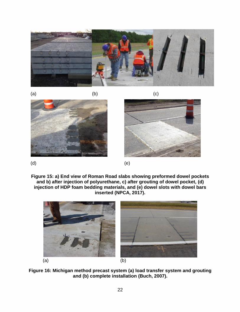
Figure 15: a) End view of Roman Road slabs showing preformed dowel pockets and b) after injection of polyurethane, c) after grouting of dowel pocket, (d)
injection of HDP foam bedding materials, and (e) dowel slots with dowel bars inserted (NPCA, 2017).
(a) (b)
Figure 16: Michigan method precast system (a) load transfer system and grouting and (b) complete installation (Buch, 2007).
23
Jersey Precast System The Jersey Precast system is another proprietary system that is being developed by a private corporation in Trenton, New Jersey (at the time of writing this report in August 2018, they are still waiting for patent and approval). Jersey Precast technology uses a slot jointed precast panel installation system. The major difference of this system from the Super-Slab system is that it incorporates steel reinforcement within its panel to aid in additional strength rather than just to support the transportation of the panel. In addition, the dowels are loosely inserted into the precast slab and then pushed into the adjacent slab using a specialized tool.
The dowel diameter is dependent upon the thickness of the slab and dowels are spaced 12” apart, transversally. Longitudinal dowel connections are only required when the length is greater than 15 feet or when new slabs are placed adjacent to each other. The jersey precast installation process begins with the removal of the existing pavement and the subbase preparation. The subbase is prepared with a bedding material primarily consisting of sand and then the subbase is graded, compacted, and graded a final time to a precision of 1/8 inch. The pavement is then set and the dowels are grouted. Once the dowels are grouted, the bedding is then grouted until the panel is at a level “flush” elevation with the existing pavement. In the dowel installation process, a ¾-inch diameter hole is generally used for an access tube for the grout and dowel installation tool.
Illinois Tollway System The Illinois Tollway System is a non-proprietary (non-trademarked) system being used by the Illinois DOT that is becoming adopted by other state agencies such as the Texas DOT. This system is very flexible in terms of allowing the contractor do as they wish for the application needed, allowing the customization of the panels to accommodate unique situations. The panels are reinforced in both directions, the width is set to match the existing pavement width, and thickness is set to match the existing pavement depth, minus about ½ inch to 1 inch to allow for bedding material. Panel lengths ranging from 6 to 15 feet have been used, with typical thicknesses of 9 to 10 inches. The Illinois Tollway authority is currently working on demonstration projects with Indiana, Iowa, and Texas, to share their technology. In essence, the Illinois Tollway has developed a series of specifications and details to cover a variety of commonly used precast panel repair methods. It is up to the engineers to select the various components to form a system best suited to the particular repair situation. The dowel slots for this system were originally designed with standard dowel bar retrofit “Sunny Side Up” connections, which are top slotted and are similar to the original Roman Road dowel slots (Gillen, 2016). Figures 17 (a) and (b) present images and schematics of these original dowel slots. Figure 17 indicates that the dowel bars are placed in the direction of the wheel path, and are spaced about 12 inches apart.
24
(a) (b)
Figure 17: Illinois Tollway “sunny side up” dowel slots: (a) typical surface view, and (b) detail of dowel slot dowel slots (Gillen, 2016)
The challenge with this type of top-slotted system is that the dowels must be grouted before it can be opened to traffic. This often means the project must be completed over the course of two days rather than one night, which creates congestion due to traffic lanes being closed for longer periods of time. Also, it takes more time and equipment to cut out these dowel slots when compared with the newly adapted slots that Illinois Tollway has implemented into their design. Illinois Tollway now utilizes pre-drill/narrow mouthed dowel connections (Gillen, 2016). They allow for easy slide in of the dowel bars, and decrease the time and equipment necessary to cut the slots manually onsite. Further, they allow for the road to open without grouting the slots given they are partially embedded into one of the roadway panels, unlike the “Sunny Side Up” slots. Figure 18 (a) and (b) present detail drawings and images of the pre-drill/narrow mouth slots.
(a) (b)
Figure 18: Illinois Tollway panel installation: (a) details of cross-section (Gillen, 2016), and (b) dowel connection (Gillen, 2016).
The construction process for the Illinois Tollway system typically begins by pre-marking the dowel bar drill locations and then pre-drilling the holes (Gillen, 2016); a gang drill is the preferred equipment for this step, shown in Figure 19. The series is compatible with most backhoes and excavators; also, pneumatic drills offer specially designed features for maximum productivity and reduced maintenance, making them ideal for full-depth
25
road repair and patching projects. The units are capable of drilling ⅝ to 2 ½ inch diameter holes at a depth of up to 18 inches. Next, the subbase is compacted and prepared to allow panel placement and leveling. Since the Illinois Tollway system is a non-proprietary system, there is flexibility in terms of how the panel can be leveled. It can be leveled as follows (Gillen, 2016):
Fine leveling sand over restored subbase (undergrout after retrofitting through injection holes);
Suspend slab over restored sub-base in proper position (undergrout before retrofitting);
High density polyurethane foam over restored subbase (no undergrout); and,
Use leveling bolts prior to undergrout, and then slabs are undergrouted through port holes.
Figure 19: Gang drill- EZ Drill Model 210 used for pre-drilling holes for dowel insertion using narrow mouthed dowel connect (Concrete Products, 2017)
Once the leveling method is determined, the slabs are typically set using a crane, utilizing pre-inserted leveling hooks and attached cables. Finally all the joints are caulked and the panel is opened to traffic (Gillen, 2016).
Utah DOT System The Utah system uses threaded bolt system to position the panels to the correct height and a quick setting grout is used to fill the space between the base and the panel. The Utah system has been used with panels of varying length including 6 feet and 12 feet long with a typical thickness of 9 inches (Higgins, 2012; Rao 2013).
Kwik Slab The Kwik Slab system is another proprietary precast system developed and patented by Kwik Slab LLC (US Patent 7134805, 2006) in Honolulu, Hawaii. This system is an interlocking precast system using two-way continuous rebar reinforcement. The rebar extends beyond the pavement and interlocks into the next slab of pavement through Kwik Joint steel couplers. The connecting rebar reinforcements are designed to be 1 in.
26
in diameter and the rebar behind the couplers are to be ¾ in. The connection is filled with high early strength grout to secure the connection. The Kwik Slab system is connected to the existing pavement by filling the gap between the pavement and the Kwik Slab with the high early-strength grout. The pavement is levelled through deep injection of high-early strength grout or plastic shims (Tayabji et al., 2013).
Rapid Roadway System The Rapid Roadway System is not a complete system as the SuperSlabTM system. Rather it is a collection of products that have been developed in California to increase productivity and improve PCP systems. It is the result of collaboration between a contractor, system designer, and a grout manufacturer. These products include the Gracie Lift which is a combination lifting point and leveling screw, the Barra Glide Load Transfer System (discussed later in this report), and a dual-purpose grout used for both slab bedding and dowel bar grouting. These products are patented and freely available for purchase by any qualified precaster that wants to use them in a precast pavement system. Rapid Cast In-Place Repair Mixtures
Types of Cast-in-Place Mixtures Concrete for rapid repair of Portland Cement Concrete (PCC) pavements can be classified into two types. One is Class V concrete typically used for full depth rapid repair, while the other is quick setting patching materials used for partial depth concrete pavement repair. The following subsections provide a discussion of these two groups of materials.
Class V Concrete This type of concrete is a cast-in-place concrete material that cures quickly; thus, rapidly opening roadway to traffic. According to NJDOT specifications, this CIP system uses an accelerating (Type C) admixture and/or Type III Portland cement, and High-Range Water Reducing (Type A) chemical admixtures. Load transfer dowels are used in the transverse direction (dowel bars). Tie bars are used longitudinally if the pavement is longer than 15 feet. The concrete is cured using wet burlap and is covered with insulating blankets to retain heat during the hydration process. Class V concrete is limited in that it cannot be used when the ambient temperature falls below 50oF (NJDOT, 2007). The pavement can be opened for traffic when flexural strength reaches 350 psi. Examples of Class V concrete mixtures are listed in Table 4.The Portland cement is Type I. The coarse and fine aggregates are crushed rock and river sand. The water reducer is high range and the accelerator is non-chloride based. The air entraining agent is a rosin based organic blend.
27
Table 4: Proportions of Class V concrete.
Quick-Setting Patch Materials NJDOT defines quick-setting patch materials as bagged, pre-prepared, manufactured cementitious mixtures that rapidly gain strength. Desirable characteristics include fast setting, rapid strength gain, non-shrink, and high bond strength. Quick-setting patch materials also have no corrosion-causing ingredients such as calcium chloride. Any additives, adhesives, or bonding agents must be provided as a ratio of one additive, adhesive, or bonding agent to one bag of product. Any patch material on the NJDOT qualified products list (QPL) can be used on an applicable project. Products are added to the QPL by the materials engineer (ME) after testing and evaluation for 1 year of field service. Above all, the manufacturers’ recommendations for mixing, water addition, and aggregates must be followed. Quick-setting patch materials for partial depth concrete pavement repair specified by NJDOT are Type 1A and 1B, and are described as follows (NJDOT, 2007): Type 1A: Products with manufacturer-specified mix proportions with aggregates that
prevent a Type 1 classification. The manufacturer specifies mixing instructions, including aggregate size, proportion, and mixing instructions. Before adding the product to the QPL, mix proportions must be approved by the ME. Ten days before placement in a project, trial batches must be approved by the ME.
Type 1B: Products come with prepackaged aggregates and/or sand. Additional aggregate should not be added and the aggregate supplier must remain constant. The manufacturer must specify the aggregate amount and gradation curve, and must remain within ±10% of the approved value and gradation.
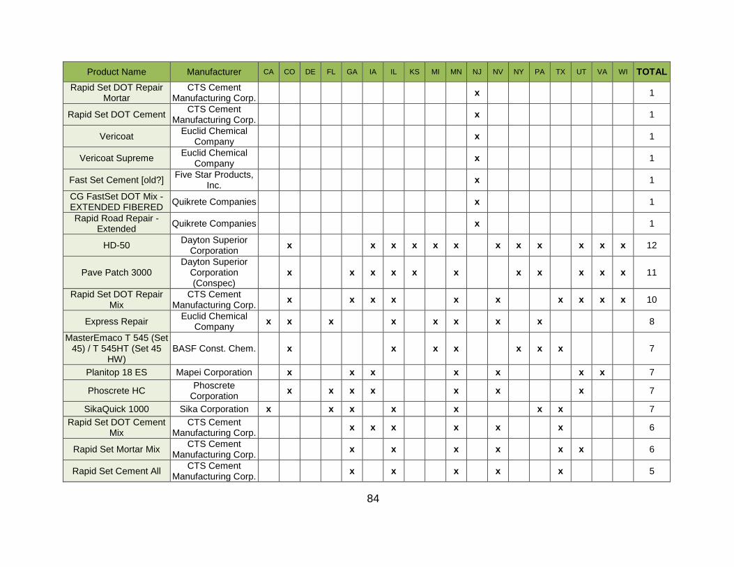
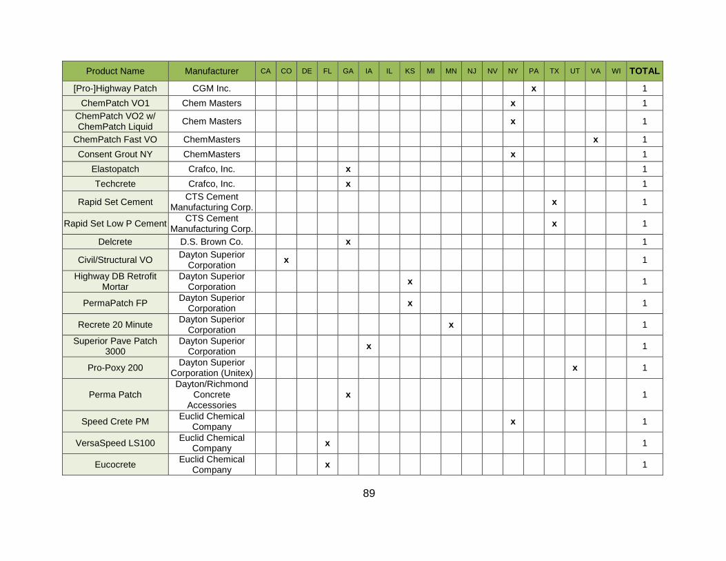
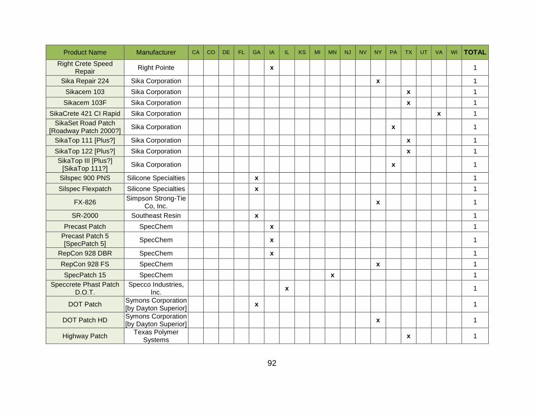
Several selected quick-setting patch materials are listed in Table 5 and described immediately after. The list is taken from a larger list of 218 quick-setting patch materials compiled by the research group from various states. A total of 18 states were surveyed. The full list of products is included in Appendix A. The products in Table 5 were selected because they are most widely approved by various SHAs, including NJDOT. Additional quick-setting patch materials were chosen because they are common or emerging technologies. Some quick-setting patch materials are approved as both Type 1 and 1A. However, none of the selected products are Type 1B. Based on NJDOT specifications, Type 1 quick-setting patch materials are used to retrofit dowel bars, whereas Type 2 are approved for vertical and overhead repairs. Three technologies
Material
Reference
Ansari & Luke (1996)
Punurai (2003)
Cement, pcy 799 799 658 658
Coarse Aggregate (3/4”), pcy 1800 1840 1850 2057
Fine Aggregate, pcy 1200 1090 1350 1241
Water, pcy 325 282 230 230
Water Reducer, fl.oz/cwt 16 12 12 16
Air Entrainer, fl.oz/cwt 1.0 0.5 0.5 0.65
Accelerator, fl.oz/cwt 32 32 40 40
28
listed in Table 5 are known rapid repair materials, but are not in the approved list of the states that were surveyed.
Table 5: Approval of the Examined Mixes by NJDOT.
Rapid Set DOT Cement Mix Rapid Set DOT Cement Mix is one of the many CIP solutions manufactured by CTS Cement. It is a blend of Rapid Set hydraulic cement and aggregates. By itself, it boasts a short setting time; high durability, including in wet environments; and high early strength, making it a potential option for accelerated pavement repair. It can be used by itself, with aggregate extender, or modified with latex, depending on the intended result. Quick Set Patch Mix: Quick Set Patch Mix concrete is an CIP technology used to repair pavement failures and distresses. Quick Set Patch Mix concrete is beneficial in that it is widely available in large quantities. Current quick set concrete technologies can reach a compressive strength of approximately 3000 psi in 3 hours and a flexural strength of approximately 1000 psi in 24 hours due to polymer reinforcement. The quick set patch, if used to reconstruct a slab of pavement, allows for the freedom of including dowels or tie bars in its design by embedding them with dowel baskets. The concrete is able to endure freeze-thaw cycles and is sulfate resistant. The Quick Set Patch Mix concrete is limited in that it cannot be used when the ambient temperature falls below 50oF. (Quikrete, 2015; Rhino Linings, 2014; CTS Cement, 2016). Polyester-Polymer Concrete: Polyester-Polymer Concrete (PPC) is a high-strength, rapid-setting material that may be an option for accelerated repair of PCC pavements. It is typically used as an overlay surface to conventional Portland cement concrete. Polyester-polymer concrete is used commonly on bridge decks due to its durability against water and deicing salts, its rapid repair time, and its reduced load on bridge structures. PPC is a composite material formed using a mixture of aggregates,
Product Manufacturer NJDOT Type No. of State
Approvals 1 1A 2
Planitop 18 Mapei X X 10
Rapid Mortar 10-60 MasterEmaco X X 10
Speed Crete 2028 Euclid Chemical X X 8
RepCon 928 SpecChem X 12
CG FastSet DOT Mix Quikrete Companies X 8
ProSpec Blendcrete HB Fuller Construction X 2
Rapid Set DOT Cement Mix CTS Cement X 1
SikaQuick 2500 Sika Co. X 14
Highway Patch Five Star Products X 7
HiCap FT Kaufmann Products X 3
Type I PC with Ca-Al Kerneos
Polyester-Polymer Concrete - 1121 KwikBond
Quick Set Patch Mix Concrete Solutions
29
polymerizing monomer, and a polyester resin with an optimal resin content of 15% (Abdel-Fattah and El-Hawary, 1999; Vipulanandan and Paul, 1993). PPC can reach a compressive strength of 5000 psi in the first few days and can reach a 28-day compressive strength of 9000 psi. Fly Ash as fine aggregate in PPC has been found to increase the strength behavior and resistance to water absorption (Varughese and Chaturvedi, 1995). Fiber and glass reinforcements can be incorporated in the mixture to alter its behavior (Greenwood, 2002; Maghraby et al., 2010). PPC can also endure freeze-thaw cycles and resist water effectively (Varughese and Chaturvedi, 1995; Kwik Bond Polymers, LLC, 2011). It can be used at temperatures as low as 40oF. Rapid Mortar 10-60 Rapid Mortar 10-60 (also known as MasterEmaco T 1060) is a rapid-setting cement-based mortar designed for repairing horizontal concrete surfaces that requires high early strength. These surfaces include bridges, airport runways, parking decks, and others. MasterEmaco T 1060 is a proprietary cement blend that requires only the addition of water. It has high compressive and flexural strengths, of 8000 psi and 850 psi respectively, after 28 days. It can be used within temperatures of 40oF and 85oF. The company that produces MasterEmaco has another variant called Rapid Mortar 10-61, which has extended working and setting times and high early strength (BASF, 2017). Type I PCC with Calcium Aluminate Cement Type I PCC with calcium aluminate cement is based on calcium aluminates rather than calcium silicates. This gives the concrete properties such as rapid settling, hardening, and drying; high strength; and corrosion resistance compared to typical concrete. It can be used in temperatures as cold as 14oF (Kerneos, 2019). Ciment Fondu®: is a proprietary cement paste based on calcium aluminates. Its chemical composition is shown in Table 6 after one day. It can be used as an additive to traditional PCC, mixed alone as cement or mortar, or with lime as an additive. Adding it to PCC or adding lime to Ciment Fondu® decreases setting time to 3-30 minutes. Concrete mixes using Ciment Fondu® as the cement powder will have setting times of four hours, compressive strengths of 7250 psi, and flexural strengths of 725 psi after one day.
Table 6: Chemical Composition of Ciment Fondu (Kerneos, 2008)).
Usual Range Specification Limit
(EN 14647)
Al2O3 37.5 - 41.0 > 37.0
CaO 35.5 - 39.0 < 41.0
SiO2 3.5 - 5.5 < 6.0
Fe2O3 13.0 - 17.5 < 18.5
MgO - < 1.5
TiO2 - < 4.0
30
Speed Crete 2028 Speed Crete 2028 is a cement-based, pre-prepared repair mortar manufactured by Euclid Chemical after they bought Tamms Industries who originally made the product. It sets quickly and achieves high compressive, flexural, and bond strength. The mix consists of blended cements and optimally selected aggregates, although extending the mix is still possible. It also contains a corrosion inhibitor which is integral to the mix (Euclid, 2018). Highway Patch Five Star Product’s Highway Patch is a one-component hydraulic cement mix optimized for horizontal repairs of concrete in trafficked areas, such as roadways and bridge decks. The patch is resistant to oil, grease, gasoline, and salts. It can be placed in environments as cold as 35°F. In normal conditions, it can be opened to traffic within 2 hours of placement (Five Star, 2017). ProSpec Blendcrete ProSpec Blendcrete was chosen because it is a fast-setting, single component mix with a water-activated powder system that can be used for horizontal or vertical and overhead uses (according to the manufacturer HB Fuller Construction Products). The mix is polymer-modified calcium aluminate cement with a corrosion inhibitor. Along with Portland and alumina cement, the mix also contains calcium carbonate, lithium carbonate, Kaolin, and quartz. This mix has a compressive strength of 5500 psi after 28 days and short setting times of 20 minutes for initial set and 30 minutes for final set (H. B. Fuller, 2016).
HiCap FT The HiCap series is a line of quick setting, cementitious mixes intended for patching. HiCap FT is a good choice for a roadway patch material with its improvements over standard HiCap: improving compressive strength to 7000 psi, increasing bond strength, and adding chemical resistance. A chemical engineering process blocks the intrusion of water and deicing chemicals. The mix is composed of Portland cement and silica (quartz), as well as acceleration, workability, and water reducing additives. The safety data sheet (SDS) also indicates the use of some alumina cements, Kaolin, and calcium sulfate (Kaufman, 2019).
Planitop 18 Planitop 18 is a fast setting cementitious repair mortar that is shrinkage-compensated and has a corrosion inhibitor. Applied neat as a mortar, it can be used for concrete repairs from ½” to 2” thickness. When it is extended with up to 80% of 3/8” pea gravel aggregates, 8” thickness can be achieved. Applications greater than 8” will require technical assistance from the manufacturer. The repair material can be applied at ambient temperatures between 32°F and 95°F without protection (Mapei, 2013). Commercial Grade (CG) FastSet DOT Mix CGFS DOT Mix is a rigid pavement repair mix manufactured by Quikrete. It was
31
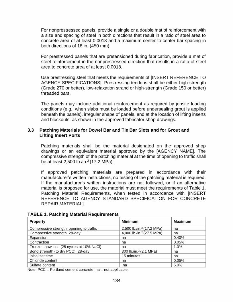
designed with the intent to meet ASTM C 928 R3 (region 3) requirements for a dry, packaged cementitious material. The mix consists of Portland and Calcium Sulfoaluminate (CSA) cements, chosen for their fast setting times, as well as sand, quartz, and special additives. The mix is fiber reinforced, which enables it to surpass all ASTM C 928 R3 requirements. It is available with a corrosion inhibitor if deemed necessary. The mix can be applied to thicknesses ½” to 2”, but can be used in thickness greater than 2” when extended with up to 30% of ½” coarse aggregates (Quikcrete, 2015). SikaQuick 2500: Sika Co. manufactures many cementitious products, several of which are concrete patch materials. SikaQuick 2500 is the single-component, rapid hardening, and high early strength cement. Its name comes from its fast setting times and 1-hour compressive strength of 2500 psi. After 28 days of hardening, its strength will increase to 8500 psi. The mix uses only Portland cement (no gypsum). Sika Co. reports that road traffic can cross in as little as 1 hour after setting. In addition, Sika Co. states the mix can be used for full depth repairs. As mortar, the applicable thickness is ¼” to 1”. When extended with aggregates, the thickness range is 1” to 6”. The recommended aggregate size is 3/8”. Repairs can be open to foot traffic in 45 minutes and vehicle traffic in 1 hour at 73 °F. The minimum ambient and surface temperature is 45°F (Sika, 2016). RepCon 928 RepCon 928 is a single-component mix with Portland cement, a polymer modifier, fiber reinforcement, and a corrosion inhibitor. These offer increased strength and durability without sacrificing ease of application. Aluminum sulfate is used as a waterproofing agent and accelerator. The mix has a compressive strength of 9600 psi at 28 days. The manufacturer, SpecChem, also makes RepCon 928 FS, which has faster set times and can be used in cold environments. The standard temperature range for RepCon 928 is 55 oF - 90oF, and 40oF - 90oF for FS version. The mix has a long working time compared to other quick-setting patch materials, with 40 minutes until initial set and final set at 45 minutes. For heavy traffic applications requiring greater than 1” inch, RepCon 928 should be extended with 3/8” aggregate up to 60% by weight (30lbs). For applications more than 4” thick, aggregates can be extended up to 100% by weight (SpecChem, 2017). The bagged properties, including bag weight, yield, and admixtures included in the mix of all of the above quick-setting patch materials are summarized in Table 7.
Mixing and Preparation The preparation and mixing of a CIP concrete materials are important procedures for ensuring proper strength attainment. Therefore, the following subsections outline the procedures for the preparation and mixing of each CIP technology.
Class V Concrete According to NJDOT Standard Specifications for Road and Bridge Construction (updated 2007), class V concrete should be mixed according to section 903.03.03 - “Mixing for Central-Plant and Transit Mixing” or section 903.03.04 - “Mixing on the Project.” These are the standard practices followed for other regular cement. Class V also requires the use of an accelerating admixture and a high-range water reducing admixture.
Rapid Set Concrete with Latex Modifier Rapid set concrete with latex modifier can be used for thicknesses of 2” - 24”. Before use, the application surface should be clean and dry. Remove all unsound material with an abrasive surface mechanically. Thoroughly saturate the area before application, but leave no standing water (CTS Cement, 2013).
33
The use of a mechanical mixer is recommended. Add 3.5 - 4.5 quarts of water to the mixer for every 60 pound bag of Rapid Set concrete. Less water will result in a stronger concrete, while more water will make it more workable. Do not exceed 4.5 quarts of water. Add the cement mix and mix until it is uniform and not lumpy, usually 1-3 minutes. Do not retemper the mix.
Quick Set Patch Mix The applied surface must be clean, sound, and free of contaminants that inhibit bonding such as oil, dirt, or wax. Some preparation methods include grinding, shot blasting, and/or scrubbing with detergent, acid etching neutralizing, and pressure washing. Instructions for mixing are as follows. Using a drill or stir mixer, add and mix one part water to four parts Quick Set Patch Mix by volume. For repairs over ½” in depth, mix in ⅜” gravel/rock, at the amount of 1–1.5 gallons for a 50 pound bag of Patch Mix. This increases strength, decreases shrinkage cracks, and increases coverage. Mix thoroughly for three minutes, then apply to dampened surface (Concrete Solutions, 2104).
Polyester-Polymer Concrete The following processes apply to Kwik Bond PPC-1121 and may not share steps with other PPC mixes (Anderson, 2013). For preparation of the road surface, perform shot-blasting to remove unwanted dirt, asphalt, curing compounds, and exposed aggregate. Follow up with scarifying, chipping, or another cleaning process. Check for unsound concrete, and remove and replace any that is found.
Next, the surface must be primed using KBP 204/103, a high molecular weight, methacrylate-based “healer/sealer” produced by KwikBond. It helps fill in cracks and bonds with the application surface and PPC. Mix 1 gallon of KBP 204 with 3 fluid ounces of 6% Cobalt Drier, a material that reduces drying time (accelerator). Stir for 10 seconds. Add 3 fluid ounces of Cumyl Hydro- peroxide (CHP), which acts as an initiator/catalyst. Stir for 30 seconds. Immediately after, empty the primer onto application surface and redistribute with a brush (paint brush, roller, squeegee, or broom). Excess primer is undesirable, however, some is unavoidable. This mix is based on a temperature of 70oF; reduce CHP to 1 ounce in high temperatures and increase accelerator and catalyst concentrations in colder weather. Typical temperature range is 40–90oF. Leave for 30 minutes before application of PPC mix.
The following mix proportions are intended for a 9 ft3 mixer. Add 4 gallons of PPC Binder Resin (KBP Epoxy LM), manufactured by Kwik Bond. Add 7–12 fluid ounces of DDM 9, another catalyst based on methyl ethyl ketone peroxide (MEKP) manufactured by Luperox. To increase strength at a faster rate in low temperatures, add 0.1%–0.4% Z-Cure accelerator. Turn on the mixer and add two 50 pound bags of B39 rock (S39 alternative) and four 50 pound bags of B-11 sand. Mix for 2 minutes. Move mix into wheelbarrow and apply. Like the primer, change the amount of catalyst based on temperature and for any traffic control requirements.
34
Place mix using a vibratory strike off screed, slip form paving machine, or standard hand finishing tools. Strike off surface at final grade (flush to pavement edge). While still wet, apply topping sand in slight excess. This creates a more textured, durable surface. Mechanically texture using spring steel lines ⅛” deep spaced ¾” - 1” apart.
Rapid Mortar 10-60 Rapid Mortar 10-60 can be applied to concrete or reinforcing steel. A concrete surface must be fully sound after curing for 28 days before preparation. Saw cut the perimeter of the repair area with a minimum depth of ½”. Refer to the latest International Concrete Repair Institute (ICRI) Guideline no. 310.2R for surface preparation to enable the best bond. For steel, all oxidation and scaling must be removed before application. Before the mixing process begins, precondition the material to 70oF ± 5oF. Add 5½ pints of water for every 50 pound bag used. If applicable, add aggregates while slowly and continuously mixing. For areas 2 to 4” deep, use 15 to 25 pounds of ⅜” aggregate. For area greater than 4” deep, add 25 to 50 pounds of aggregate. Mix until homogenous, for a minimum of 3 minutes. To apply, scrub in a thin layer of bond coat, place repair mortar, level to surface, and finish. The mixing process should take no more than 15 minutes (BASF, 2017).
Type I PCC with Calcium Aluminate Cement Any formwork (steel or wood) should be clean, free of laitance dust, watertight, and coated with mold oil. For good bonding, concrete should be soaked with water. Mixing can be done in a powered mixer or with a shovel. The mix proportions are as follows:
For concrete: 10 liters of water, 40 liters of gravel, 25 liters of sand, 25 kilograms of Ciment Fondu
For mortar: 10 liters of water, 40 liters of sand, 25 kilograms of Ciment Fondu
Never exceed 10 liters of water for 25 kilograms of Ciment Fondu
Ingredients are added in this order: 80% of the prepared water, gravel, Ciment Fondu, sand, and finally the remaining water. Compaction should be done through rodding or vibration (Kerneos, 2019).
Speed Crete 2028 The concrete application surface must be structurally sound with all loose and deteriorated concrete removed as well as free of contaminants such as dust, dirt, paint, etc. Mechanically abrade the surface to ICRI guidelines 310.2 CSP 5-7 (medium shot blast, medium scarification, or heavy abrasive blast). Clean area again. Priming can be done in two different ways. Either prime concrete or steel with a coat of DURALPREP A.C., a bonding agent made by Euclid Chemical, using a brush or spray, then allow to dry. As a secondary condition, create a Saturated Surface Dry (SSD) condition using a scrub coat of Speed Crete 2028, then apply concrete before this dries. Mix using a drill mixer for single bags or a paddle mixer for larger batches. Proper mixing order is adding water first, then Speed Crete 2028 and mix for 4 minutes, then extending if needed. Add 2.25–2.5 quarts of water per 50 pound bag. For areas under
35
1.5” in depth, the mix can be used neat. For areas greater in depth, either extend the mix with 3/8” pea gravel (up to 40 pounds per bag) or apply multiple layers in maximum 1.5” increments, but no less than ½”, allowing final set before adding another layer. When applying, work the mix firmly for a good bond. Screed and work with a trowel to level. Finish as desired. If the weather is windy or hot, wet curing is recommended. If the air is less than 45oF, heating the repair area and using warm water for mixing will ensure proper strength gain (Euclid, 2018).
Highway Patch All loose or weak concrete, oil, grease, and other contaminants must be removed prior to mixing. The surface must be clean, sound, and properly roughened. Edges of the substrate concrete should be vertical. Pre-soak repair area with water, but leave no standing water. Any reinforcing steel should be undercut by ¾” or 2 times the maximum aggregate size, whichever is greater. Recommended application temperatures are 35 to 90oF with optimal temperatures ranging from 55 to 75oF. Heat or cool the repair area (not the highway patch material) as necessary (Five Star, 2017). Mixing can be done with a drill paddle mixer or a standard paddle mixer. Add premeasured water first, then concrete, mix for 4–5 minutes, then add any aggregates as desired. Working time is 10 minutes. The recommended water amount can be found on the packaging. Regarding aggregate extension amounts, thicknesses of 1”–2” will require 0% extension by weight, thicknesses of 2”–4” will require 50% extension, thicknesses of 4”–6” will require 60% extension, and thicknesses of more than 6” will require 80% extension. During application, place in full depth and work from one side to the other. If this is not possible, place continuously. Firmly work material into substrate for a good bond. Once filled, screed the repair level and finish with desired texture, then apply curing compound (Five Star, 2017).
ProSpec Blendcrete Substrate concrete surface must be clean, hard, and free of dirt, loose particles, waxes, oils and greases, efflorescence, and other foreign materials. Expose and clean reinforcing steel leaving a minimum ¾” gap behind the steel. Abrade concrete to a rough surface to promote adhesion. Area should be saturated surface-dry (SSD) with no standing water. The manufacturer recommends applying a thinly mixed bond coat of Blendcrete, not allowing this coat to dry before application (H. B. Fuller, 2016). Mixing is recommended to be done with a paddle mixer, but a drill or trowel can be used for small batches. Add 4–5 quarts of water per 50 pound bag. Next, add the appropriate amount of Blendcrete. Mix for 1–2 minutes. For areas deeper than 2”, add 15 pounds of clean, SSD 3/8” gravel. Mix for an additional minute. For areas shallower than ½”, use 4–5 quarts of TEC Patch Adhesion.
Application temperature should be no less than 40oF, and temperatures outside of 60 to 80oF will produce a retarding or accelerating affect. Typical work time is 15 minutes. Apply mix to the entire surface with force. Slightly overfill the area, then, after initial set, shave to final desired profile using a trowel. If required for deep areas, several lifts can
36
be done after scoring the old layer to improve bond. Curing is to be done according to ACI procedure 308.
HiCap FT The surface must be structurally sound, clean, and free of oils and contaminants. Edges should be undercut to a minimum of ¼” depth. Clean exposed steel reinforcement. Roughen intended bond surfaces for mechanical adhesion. Pre-wet the application area for 15 minutes immediately before application (while mixing). The surface should be SSD. If the temperature is below 35oF, do not wet. A low RPM ½” drill paddle mixer is recommended. Water (3.4 – 3.6 quarts) should be used for each 50 pound bag of HiCap. If the weather is cold, warm water should be used. Mix water with cement until blended, but not more than 1 minute. No additives or admixtures should ever be used. Scrub the mix into the concretes pores by hand (with gloves), then pack the rest of the area with a trowel, slightly overfilling. After a short set, shave to final shape, moving the trowel towards the edges at all times. Texture if desired. Curing is essential, and the manufacturer recommends to use Krystal 25 Emulsion, Krystal 30 Emulsion, or a state approved Thinfilm Series product (Kaufman, 2019).
Planitop 18 All substrate must be clean, stable, and free of contaminants that could negatively affect bond strength before application. Mechanically prepare the surface through shot-blasting, abrasive blasting, water-jetting, or scarifying. Ensure substrate is SSD before application. Exposed reinforcement steel should be cleaned and coated with a corrosion inhibitor such as Mapefer 1K or Planibond 3C. The air and material temperature must remain between 45 and 95oF during application and at least 12 hours after application. A drill mixer or mortar mixer can be used. Add 2.5–3.0 quarts of water to a clean mixing container. Slowly add Planitop 18 while mixing for 2–3 minutes. Fills with a depth of less than 2” should be done neat, while fills of 2”–8” should be extended up to 80% by weight with washed, SSD, 3/8” gravel. Apply with a trowel with 15 minutes of mixing. This mix is self-curing, but water-based curing methods (not solvent-based) such as damp burlap or white polyurethane sheeting can be used (Mapei, 2013).
CG FastSet (CGFS) DOT Mix Substrate surface should be clean and solid, free of failed concrete and contaminants. Repair areas should have a vertical edge extending ½” or more. Surfaces should be rough, which can be achieved by acid etching or chipping. After this step, the concrete should be cleaned by water blasting. Remove excess water to leave the concrete in an SSD state. The recommended water amount is 4 quarts with a 50 pound bag of neat mix and an 80 pound bag of extended mix, with some adjustment to create a place-able consistency. Do not exceed 7” slump. Mix CGFS DOT Mix mechanically in a standard mortar mixer
37
for 3 minutes. If the repair is deeper than 2”, up to 25 pound of ½” gravel should be added to the mortar. Place material quickly and consistently with light rodding to remove air bubbles. Once complete, strike off and screed. Cut the concrete away from any edge forms with a trowel or edge tool. Finish to final texture as desired. The curing process is very important, and is most easily achieved with Quikrete Acrylic Concrete Cure and Seal through application with a brush, roller, or spray (Quikcrete, 2015).
SikaQuick 2500 Surface must be sound and clean, free of bond-inhibiting contaminants. If the area is less than ¼” in depth, saw off the edges. Through appropriate mechanical means, obtain an exposed aggregate surface with a minimum surface profile of ± 1/8” (ICRI guidelines 310.2 CSP 6+). Saturate surface of repair area with water, then remove any excess. Prime area with a scrub coat of SikaQuick 2500, applying concrete before this coat dries. Add 5 pints of water to a mortar mixer. Add one 50 pound bag of concrete mix, followed by another ½ pint of water if the desired consistency is not achieved. In hot or cold weather, setting times can be improved by using cold or hot water. For depths greater than 1”, add 25 to 30 pounds of 3/8” aggregate. To apply, scrub the mix into the substrate to fill all pores and holes. Fill completely and strike off the excess. Finish as desired. The entire process should take not more than 15 minutes. Start curing immediately after finishing. Curing is usually done with wet burlap and polyethylene and a fine mist of water, or something else that follows ASTM C 309 (Sika, 2016).
RepCon 928 Surface concrete must be sound and free of contaminants. To ensure increased durability, saw cut edges to leave 1/8” vertical faces. Mechanically abrade the entire surface to a minimum of ICRI 310.2 guidelines to CSP 5+ (medium scarification). All concrete in the repair area must be in an SSD state with no standing water. Following this, prime concrete with a spray or brush coat of SpecPrep SB, or apply a scrub coat of RepCon 928 with a stiff-bristle brush. For mixing, first add 4.75–5.25 pints of water to a mixer (low speed drill or mortar mixer) for each 50 pound bag of RepCon 928. Add the cement powder slowly while mixing for 2–3 minutes. No extension is required for depths of 1”–2”. For DOT and heavy traffic situations 1”–4” in depth, extend with clean, SSD 3/8” gravel, up to 60% by weight. For depths of 4” and greater, extend up to 100% and mix for 2 extra minutes. Any water added from the aggregate should be subtracted from the initial amount. To begin placement, trowel or screed the mix firmly into the repair area to ensure a good bond. Fill until level with the surroundings, wait for initial set, and then perform hand troweling. Finish to match the surrounding pavement texture without adding extra water. Finishing can be aided with a light spray of SpecFilm. The recommended placement temperature is within 55 to 90oF (SpecChem, 2017). Table 8 presents a summary of the preparation and mixing procedures for all CIP materials discussed above. All the information is based on manufacturer literature.
38
Table 8: Preparation and Mixing Instructions of CIP Mixes.
Mixer Type mortar, drill mortar, drill mortar, drill mortar, drill
Application
Scrub Coat Y Y Y Y Y
Layers Y Y
Curing:
Curing Time (hr.) -24 1
Allowed:
Additives N N
Retempering N N N
40
Strength
This section covers compressive strength, flexural strength, and initial and final setting times of several different CIP concrete materials. ASTM C 928 (Standard Specification for Packaged, Dry, and Rapid-Hardening Cementitious Materials for Concrete Repairs) defines three classes of concrete or mortar (R1, R2, and R3) based on their compressive strength. The compressive strength of concrete are classified from lowest compressive strength (R1) to greatest compressive strength (R3). Further details can be found in Table 10. The SHRP C-206 manual suggests opening criteria of 2000 psi in compressive strength and 300 psi in flexural strength. State agencies also may set strength requirements for CIP materials. For example, NJDOT has limits for compressive strength, flexural strength, and setting time. A partial depth concrete repair or patch in NJ must have a compressive strength of 2000 psi to open to traffic. Quick-setting patch materials are required to have a 3-hour compressive strength of 2000 psi, 24-hour strength of 3000 psi, 7-day strength of 4000 psi, and 28-day strength of 4500 psi. NJDOT also requires that the setting time for patch materials is a minimum of 15 minutes (NJDOT, 2007). The compressive strength, flexural strength, and set time properties are shown in Figures 20, 21, and 22 respectively. The data is also summarized in Table 10. All data presented is as reported in manufacturer literature.
Class V Concrete NJDOT specifications (903.04) detail the strength requirements for pavement repair mixes Class V and Class E. Table 903.04.02-1, reproduced below initial set data is unavailable. Table 9, outlines the strength requirements for these mixes. For class V, the repair cannot be opened to traffic until flexural strength is more than 350 psi (NJDOT, 2007). Figure 20 and Figure 21 shows the requirements for Class V concrete are well below what is achievable using other proprietary CIP technologies. Additionally, testing done on a class V mix shows that it does not meet the minimum required strength. The 28-day compressive strength meets the requirement with a compressive strength of 5914 psi; however, the 6.5-hour flexural strength is only 338 psi (Punurai, 2003). Another study of a slightly different mix recorded a 6.5-hour flexural strength of 353 psi (Punurai, et al., 2007) After 28 days, class V concrete has flexural strength of nearly 1000 psi. It also has shown the longest setting time with final set taking 5 hours. Initial set data is unavailable.
Table 9: Class V strength requirements (Table 903.04.02-1 NJDOT, 2007) Class V Class Design Strength 28 day Compressive Strength (psi) 3700 6.5 hour Flexural Strength (psi) 350 72 hour Compressive Strength (psi) - Verification Strength 28 day Compressive Strength (psi) 4500 6.5 hour Flexural Strength (psi) 390 72 hour Compressive Strength (psi) - Maximum Water-Cement Ratio (lb./lb.) 0.40 Maximum Cement Content (lb./cy) 611
41
Rapid Set DOT Cement Mix with Latex Modifier Rapid Set DOT Cement Mix has a compressive strength of 3600 and 6500 psi after 3 hours and 28 days, respectively. From Figures 20 and 21, it can be observed that the initial strength is above average; however, it becomes below mid-range over time. Flexural strength after 4 hours is 426 psi, increasing to 550 psi after 28 days. This is low compared to other mixes, which are generally 850 psi or more. The Rapid Set mix, however, has low set times, with 18 minutes until initial set and 27 minutes until final set. The set time was determined following ASTM C 191 with Vicat needles. This method is not directly comparable to tests done following ASTM C 403, but doubling C 191 values is roughly comparable to C 403 values (CTS Cement, 2013).
Quick Set Patch Mix Quick Set Patch mix starts with an average compressive strength of 2500 psi in 1 hour. From Figure 20 it can be observed that this material achieves greater than average compressive strengths at 28 days (8100 psi). It is unknown what test methodology was followed. Flexural strength is also extremely high as after 24 hours it exceeded 1100 psi and reaches 1880 psi after 28 days. This is the greatest flexural strength found in this reviewed literature. Initial setting time is also low, occurring after 10–15 minutes and final set occurs in just under one hour (Concrete Solutions, 2014).
Polyester-Polymer Concrete Polyester-polymer concrete (PPC), such as those supplied by KwikBond, are
advantageous for rapid roadway repair given their relatively fast curing time, high
flexural strength, and durability. According to research conducted for the Washington
State Department of Transportation, PPC concrete can have a cure time of 2 to 4 hours.
Within 24 hours, PPC can reach compressive strengths of up to 4000 psi and after 28
days the compressive strengths reach 7000 psi. Flexural strength is also high with
values of 1500 to 2000 psi in 28 days, which, at the high estimate, would be the highest
flexural strength in this report (test methodology is unknown for these claims). Its final
setting time following ASTM C 266 with Gillmore needles ranges from 30 min to 120
min depending on the amount of peroxide initiator. Initial setting time data is
unavailable. The values obtained from ASTM C 403, C 191, and C 266 are not directly
comparable. C 191 (Gillmore) is roughly double C 403, and C 266 (Vicat) is roughly
35% greater than C 191 (Anderson, 2013).
Rapid Mortar 10-60 Strength testing was conducted by MasterEmaco at the optimal temperature of 73oF. Compressive strength following ASTM C 109 with 2” cubes was determined to be 2000 psi at 1 hr., 4000 psi at 1 day, and 8000 psi at 28 days. Following ASTM C 39 with cylinders, 28 day compressive strength was 7400 psi. This ranks well compared to other mixes (Figure 20). Flexural strength (Figure 21), however, is below average with a 1 day flexural strength of 700 psi and 850 psi after 28 days following ASTM C 348 with prisms. Setting time is just comparable to Rapid Set DOT Cement Mix, with an initial setting time of 16 min and final of 28 min. Both of these were done following ASTM C 191 with Vicat needles, so they can be adequately compared (BASF, 2017).
42
Type I PC with Calcium Aluminates Type I PC with calcium aluminates ranks high in compressive strength and average in flexural strength (Figures 20 and 21). The 6 hour compressive strength is 4350 psi, with 1 day and 28 day strength at 7250 psi and 8700 psi, respectively. Flexural strength is 940 psi after 28 days. These high strengths come at a cost of increased setting time of several hours instead of minutes like most of the other mixes. Initial set occurs in 2 hours and final set in 4 hours, but it is generally around 2.5 hours and 3 hours according to the product data sheet (PDS). As Kerneos has its head office in France and most of its plants are in Europe, all testing is done to European standards. Strength data follows British Standard (BS) EN 196-1 with 40x40x160mm prisms with composition according to EN 14647 (1350g sand, 500g cement, 200g water). Setting time follows the same for composition and preparation, and is measured according to NF P15-431 and NF P15-300. It is very important to keep in mind that unless proved otherwise, this data cannot be compared directly to data from ASTM standards (Kerneos, 2019).
Speed Crete 2028 Similar to Type I PC with Calcium Aluminates, Speed Crete 2028 has high compressive strength and average flexural strength. It starts with comparably low compressive strengths at 1000 psi after 1 hour, but increases to 5000 psi in 3 hours and has a 28 day compressive strength of 9000 psi. This is one of the highest values following ASTM C 109. Flexural strength is fairly standard—700 psi at 1 day and 950 psi at 28 days. Setting times are about average with respect to other CIP technologies. Initial setting time occurs in 15 to 25 minutes, with final set occurring in 30 to 35 minutes (following ASTM C 266 with Gillmore needles) (Euclid, 2018).
Highway Patch Five Star’s Highway Patch is missing some important data which prevents determining its viability. Following ASTM C 109 with 2” cubes the compressive strength is average compared to other CIP technologies. This procedure, however, generally produces greater compressive strength values than ASTM C 39 with cylinders. Compressive strength measurements are found at 2000 psi after 2 hours and increase steadily to 7000 psi after 7 days. No data is provided for 28 days. Flexural strength is 400 psi after 3 hours, which is acceptable. No further data is provided, so it is unclear the ranking of the penultimate flexural strength. No data for setting time is given (Five Star, 2017).
ProSpec Blendcrete ProSpec Blendcrete has one of the lowest compressive strengths of all the mixes researched as can be seen from Figure 20. The compressive strength is 3000 psi at 3 hours, but has a 28 day strength of 5500 psi. This is the lowest final compressive strength. Though this mix has the lowest 28 day compressive strength, it can be still be considered as an CIP technology because it exceeds NJDOT requirements. The flexural strength is more comparable to other CIP mixes, with 1142 psi recorded after 24 hours following ASTM C 348 with prisms. The flexural strength ranks above average with a 28 day value of 1180 psi. Unlike the other calcium-aluminate based cement in
43
this comparison (i.e. Ciment Fondu) setting times are not long. Initial and final setting times are fairly standard with times of 20 and 30 minutes, respectively, following ASTM C 191 with Vicat needles (H. B. Fuller, 2016).
HiCap FT HiCap FT has very low compressive strength of 1500 psi after 2 hours and 2100 psi after 4 hours. Between these two times, this bagged mix falls below NJDOT requirements, if interpolation is done, as seen in Figure 20. The compressive strength increases significantly to a value of 7000 psi at 28 days following ASTM C 109. The only flexural strength data available shows a slightly below average 930 psi after 28 days following ASTM C 348 with prisms. Similar to most mixes, HiCap FT has initial and final setting times of 20 and 34 minutes following ASTM C 191 with Vicat needles (Kaufman, 2019).
Planitop 18 Planitop 18 has compressive strengths of 2500 psi after 1 hour following ASTM C 109. This increases to 5500 psi by the second hour. From Figure 20 it can be observed that Planitop 18 remains the mix with greatest compressive strength until except for the 28 day compressive strength, where it falls to second place with 9400 psi. Flexural strength is also very good: 900 psi at 1 day and 1480 psi at 28 days makes it stand out from the crowd. Initial set occurs in a minimum of 10 minutes and final set occurs in no more than 35 minutes (no test method given). (Mapei, 2013)
CG FastSet DOT Mix Commercial Grade FastSet (CGFS) DOT mix has consistently high compressive strength. The 3-hour strength is 4500 psi and increases to 9000 psi at 28 days following (ASTM C 109), which is above average in comparison to other CIP technologies. No data is available for flexural strength. Initial set occurs in a very low 15 minutes, and final set occurs in 33 minutes according to ASTM C 191 with Vicat needles (Quikcrete, 2015).
SikaQuick 2500 SikaQuick 2500 has compressive strengths of 2500 psi at 1 hour, 5700 psi at 1 day, and 8500 psi at 28 days (following ASTM C 109). This is above average, as seen in Figure 20. Flexural strength is about average with 580 psi after 6 hours, increasing to 1100 psi at 28 days (Figure 21). Following ASTM C 266 with Gillmore needles, initial set occurs in a low 12 – 24 min and final set takes 20 – 40 min. This is a fairly broad range; it could be very short or slightly long compared to most other mixes. (Sika, 2016)
RepCon 928 RepCon 928 has the highest 28 day compressive strength of 9625 psi following ASTM C 109. RepCon 928 has an average compressive strength of 3200 psi at 3 hours. Figure 21 shows the flexural strength is comparably low at 7 days with 750 psi, but increases to an above average 1150 psi at 28 days. This mix has higher setting times compared to the other CIP mixtures considered in this review. Initial set occurs after 40 minutes, with final set at 45 minutes following ASTM C 266. (SpecChem, 2017)
44
Figure 20: Compressive Strength of CIP Rapid Repair Mixtures
Figure 21: Flexural Strength of CIP Rapid Repair Mixtures
28d
28d
7d
7d
3d
3d
1d
1d
0
1000
2000
3000
4000
5000
6000
7000
8000
9000
10000
1 10 100 1000
Co
mp
ressiv
e S
tren
gth
(p
si)
Time (hr) (log scale)
PPC - 1121
Rapid Set Concrete Mix
Quick Set Patch Mix
Rapid Mortar 10-60
Type I PC w/ Ca-Al
Speed Crete 2028
Highway Patch
ProSpec Blendcrete
HiCap FT
Planitop 18
CG FastSet DOT Mix
SikaQuick 2500
RepCon 928
ASTM C 928: Class R1
ASTM C 928: Class R2
ASTM C 928: Class R3
NJDOT Specifications
Class V Concrete
NJDOT Class V Spec
1d
1d
3d
3d
7d
7d
28d
28d
6.5hr
6.5hr
0
200
400
600
800
1000
1200
1400
1600
1800
2000
1 10 100 1000
Fle
xu
ral S
tre
ng
th (
psi)
Time (hr) (log scale)
Class V Concrete
PPC - 1121
Rapid Set Concrete Mix
Quick Set Patch Mix
Rapid Mortar 10-60
Type I PC w/ Ca-Al
Speed Crete 2028
Highway Patch
ProSpec Blendcrete
HiCap FT
Planitop 18
CG FastSet DOT Mix
SikaQuick 2500
RepCon 928
NJDOT Specs for Class V
45
Figure 22: Setting Time of CIP Rapid Repair Mixtures
46
Table 10: Summary of Strengths and Setting Times of CIP Rapid Repair Mixtures
* test was not done using the standard test methods recommended, see product strength description for clarification + test method used is unknown # Product Data Sheet (PDS) [] NJDOT specification provided exclusively for class V concrete
48
Effects of Latex Modifier
As stated previously, Latex modified concrete (LMC) is primarily used in overlay applications such as bridge decks, elevated ramps, and other roadways that require surface rehabilitation. One such modifier is Trinseo Modifier A/NA Latex. A study performed by a third-party compares standard concrete and latex modified concrete (Trinseo, 2015). The latex properties, concrete mixes, and results are shown below in Table 11, Table 12, and Table 13, respectively. This modifier meets all requirements specified in Report Number FHWA RD-78-35, “Styrene-Butadiene Latex Modifiers for Bridge Deck Overlay Concrete.” In a concrete mix with a latex modifier, the amount of fine aggregate increases while coarse aggregate and air content decreases. Water to cement ratio also decreases compared to a standard mix. Slump also increases. Looking at strength results shows a tradeoff: adding latex causes compressive strength to increase 30% (28 days) and flexural strength to increase 10% (28 days), with 50% strength increase after 1 day. However, bond strength decreases to about 60% of traditional values. Rapid Set Latex Modified Concrete (RSLMC) allows typical 7 days strength to be achieved in 3 to 4 hours. The LMC is able to achieve a strength of 2,500 psi in 3 hours. It was developed by Dow Chemical Company (now Trinseo) with CTS Cement in 1989. This pavement technology uses a mixture of early strength hydraulic cement with a latex (polymer) modifier, at a latex-to-cement ratio of approximately 1 gallon of latex admixture per 26.8 pounds of cement. This mixture also incorporates fine and coarse aggregates and water, using a water-to-cement ratio of no more than 0.40. The LMC is cured using wet burlap and a thin polyethylene insulator. As with most CIP technologies, the use of embedded load transfer dowels and tie-bars are possible through the use of dowel baskets and reinforcing bars. The limitation of this technology is that it cannot be cast when the ambient temperature is above 80oF or below 45oF, or when it is raining (Modified Concrete Suppliers, LLC, 2017; Sprinkel, 1998; Federal Highway Administration, 2015). Currently, NJDOT has the following mix design for Latex Modified Very Early Strength (LMVES) concrete surface course2. The mixture is for constructing full depth repairs. The mixture has been demonstrated to attain the specified concrete strength within the time restrictions of TYPE 1A rapid repair materials. Rapid Set Cement (lbs./yd3) ....................................................................................611
Latex Emulsion Admixture (lbs./yd3) .......................................................................192 Fine Aggregate (lbs./yd3) ........................................................................................1617 Coarse Aggregate, Size No.57 (lbs./yd3) ................................................................1418 Water (lbs./yd3) .......................................................................................................108 Water/Cement Ratio................................................................................................0.34 Retarder (lbs./yd3) ...................................................................................................2.4 Retarder % based on cement .................................................................................0.4
2 Information provided to the authors by NJDOT in Word document titled Section_453_Full Depth Concrete Repair with Latex Modified Rapid Set Concrete.
Coarse Aggregate 4.B.1 6.62 or 8.28 8.28 6.64 6.88
Latex (46% solids) 4.B.1 N/A N/A 3.28 3.28
Water:Cement Ratio 4.B.1.3 0.50 (adjust. allowed) 0.52 0.4 max 0.34
Slump, Initial (4 min) (in) 4.B.1.3
less than LMC 4 4 to 6 5
Slump, Time to 50% Loss (min) 4.B.1.3 Measured 46
± 25% of Conventional
57 (24% change)
Air Content (%) 4.B.1.3 5 to 7 5.4 6 max 6
Fine:Coarse Volume Ratio 4.B.1.3
60:40, 50:50 if slump < 3" 50:50 60:40 60:40
50
Table 13: Latex Additive – LMC compared to conventional concrete in strength and durability (Trinseo, 2015)
Compressive Strength (ASTM C 39)
Time (d) Conventional LMC Requirement Result
1 1927 3212 > 75% 167%
28 4945 6400 > 75% 131%
42 4960 6450 < 20% loss 1% gain
Flexural Strength (ASTM C 78)
Time (d) Conventional LMC Requirement Result
1 380 585 > 100% 154%
28 745 825 > 100% 111%
42 670 975 > 100% < 25% loss
145% 18% gain
Bond Strength (ASTM C 882)
Time (d) Conventional LMC Requirement Result
1 3212 1850 > 45% 58%
28 6400 4950 > 45% 77%
42 6450 4010 > 45% 62%
Scaling (ASTM C 672)
Sample Cycles Visual Rating Scaled Material (lb./ft3)
1 50 3 0.489
2 50 3 0.476
3 50 3 0.467
Average 50 3 0.477
Performance of Accelerated Concrete Rehabilitation Systems
Precast Concrete Pavement The University of California at Davis (UCDavis) has conducted an accelerated pavement testing study to evaluate the Super-Slab system (Kohler et al., 2007). In this study, two lanes, with five panels in each lane, were constructed at UCDavis and subjected to accelerated loading using a Heavy Vehicle Simulator (HVS). Accelerated loading was applied to the Super-Slab lanes under both dry and wet conditions and also before the application of grout and after grouting. The researchers started the loading sequence by first applying up to 100 kN of loading using truck tire configurations. The researchers then increased the magnitude of loading for up to 150 KN using aircraft tire configurations. Based on this study, Kohler et al. (2007) reported that the evaluated Super-Slab system of precast system can be safely opened to traffic in the un-grouted condition. The researchers also reported that the estimated life of the Super-Slab system is between 140 and 240 million Equivalent Single Axle Loads (ESALs). The researchers also noted that the failure mechanism of the Super-Slab system was no different than that typically seen in cast-in-place jointed concrete pavements.
51
In addition to the study by Kohler et al. (2007), the Strategic Highway Research Program II (SHRP2) funded a comprehensive project for evaluating precast pavement repairs throughout the country. According to Tayabji et al. (2013), the Super-Slab system has been the most widely used PCP repair system with five states conducting seven different repairs (both intermittent and continuous) using this system. More installations have occurred since the data cited in the reference report. The researchers reported that the Super-Slab system consistently achieved a load transfer efficiency (LTE) greater than 80%. The panels showed transverse cracking in three of their projects, but only one project's cracking appeared to be serious. In two of the Super-Slab projects, settlement was observed of up to 1 inch. Tayabji et al. (2013) indicated that a "better technique may be needed for preparing the bedding when granular bases are used, as these bases, if disturbed during removal of the existing pavement slab, cannot be effectively recompacted as part of the precast panel installation process.” Tayabji (2016c) discussed the results of a demonstration project on the Madison Beltline Highway/U.S. 12 in. Wisconsin. This project was installed in 2014 over a 7-mile stretch in an intermittent repair procedure using a total of 623 panels. The Super-Slab system was used and the panels were 12 ft. wide and varied in length from 6 to 10 ft. and were 10 in. thick. Repair areas ranged from a single panel to 192 ft. continuous stretch. The project is too recent to provide long term behavior information; however, the lessons learned were summarized to improve future practice:
The use of a template for saw-cutting worked better than using a laser to align transverse saw cuts for the repair areas. Proper saw-cutting was critical to ensure good fit of the panels. Proper training and experience from the saw cutting crew was also critical. Inexperience led to poor fit.
At least two inspectors are needed to ensure good quality work. Inspectors need to verify the contractor’s lane width measurements, layout of transverse joints, panel placement, and grouting operations.
Project specifications were not clear if the repair area for payment was the area of the repair or the area of the panel. This was addressed for subsequent projects by specifying that it was the area of the panel. This simplifies recordkeeping (same dimensions/area as indicated by the precaster) and does not reward the contractor for excessive, out of tolerance, existing concrete slab removal.
Surveys should be used to determine specific width and length of each required repair rather than assuming a standard or exact panel width. Otherwise it will be difficult to meet edge gap requirements.
Tayabji et al. (2013) evaluated the installation and performance of the Roman Road System installed during a highway repair project in New York. This project, in NY, was tested during day time in mid-2010. Based on this testing, it was observed that no cracking was found in the tested panels and joints appeared to be in "good condition.” The transverse joint deflection averaged about 0.17 millimeters and had a LTE of about 70% (Tayabji et al. 2013).
52
Buch (2007) conducted a study for evaluating the field performance of an accelerated pavement repair project rehabilitated using the Michigan precast system. In this project, 21 failed highway slabs (9 on I-675 and 12 on M-25 roadways) were replaced with 21 slabs produced and installed according to the Michigan system. Buch conducted distress surveys and Falling Weight Deflectometer (FWD) testing to assess the effectiveness of the precast panels. Based on their field evaluation results, Buch (2007) reported that some panels, on I-675, have cracked in the vicinity of the dowel bars with the majority being in good to acceptable conditions. Similar observations were also reported for the panels installed on M-25 roadway. In both roadways, the Joint Load Transfer Efficiency (LTE) ranged from 60 to 90 percent depending on the condition of the panel.
Accelerated Cast-in-Place Concrete Repair Materials All numerical data mentioned in the performance section of this report has been tabulated in Table 14. The passing requirement(s) for each test are also been shown Figures 23 through 25. All data was achieved following the ASTM C 928 recommended test methods, as reported by the manufacturer, unless otherwise noted.
Class V Concrete For class V concrete, there is a lack of long-term durability performance data. Only limited length change data is available from an NJIT study (Punurai, et al., 2007). Shrinkage values are higher than most other cements tested at -0.108% in air (control mix) and -0.098% with a slightly modified mix following ASTM C 490.
Polyester-Polymer Concrete A field study conducted by the Washington State DOT intended to determine if PPC overlays could prevent the increased wear caused by studded tires (Anderson, 2013). Three 60-foot long test sections were installed on I-90 plagued by rutting damage: the first section had the wheel path ruts filled, the second section had the wheel paths milled to 3 feet across and 1” down and then filled, and the third section was milled completely and covered in a 1” overlay. Pull-out testing on a trial section following ASTM C 1583 found the underlying concrete failed before the overlay, meeting the requirements of the specification. Average pull off stress was 419 psi. Performance of the sections will be monitored, with WDOT stating a minimum of five years until a final performance report is released, with that time being extended if no wear was quantifiable.
Rapid Set DOT Cement Mix Rapid Set DOT Cement Mix performs well in all metrics of durability except for one: freeze-thaw. Its relative dynamic modulus (RDM) dropped to 40% after 140 cycles and the test was stopped. This is well below failure criteria of 90% as defined by the NJDOT standard specifications. Total length change is the lowest of any mix, with individual values of -0.04% in air and +0.02% in water. This test was also completed following ASTM C 490 and achieved the same value in air and +0.032% in water. Bond strength is low compared to others at 2200 psi after 28 days, but it is acceptable. Scaling is very good, with none observed after 50 cycles of freeze-thaw (CTS Cement, 2013).
53
Quick Set Patch Mix The product data sheet for Quick Set Patch Mix contains no durability data, and no testing results could be found elsewhere.
Rapid Mortar 10-60 Overall, 10-60 is one of the most durable mixes tested. It passes all tests with good margins. After 300 cycles, its RDM remained at 100%, which is unmatched by any other mix present. Shrinkage is fairly low with 0.05% shrinkage in air and 0.03% expansion in water. Bond strength is above average, with values of 2300 psi after 1 day and 2600 psi after 28 days. Initial bond strength is very high, but it does not increase very much over time. No scaling was observed after 25 cycles. (BASF, 2017)
Type I PC with Calcium Aluminate From 1930-1932, a pier at the port of Halifax, NS, Canada, known as pier B, was constructed. It is made of nearly 20,000 tons of calcium aluminate cement (CAC) (Ciment Fondu) made into cribs with a foot thick outer barrier of regular concrete. In the extremely harsh conditions, submerged underwater with about 100 freeze-thaw cycles yearly, it has remained in regular use even today with general maintenance. A 1993 study shows cylinder core compressive strengths range from 4200–7100 psi, and very little conversion was noted. Conversion is an irreversible process where low density hydrates transform to high-density hydrates. The low temperature most likely slowed this process. Although no in-depth quantitative study has been performed, in real-world scenarios, CAC has shown to be extremely durable. (Kerneos, 2019)
Speed Crete 2028 Speed Crete 2028 has typical freeze-thaw resistance with an RDM of 98% after 350 cycles. Most of the reviewed mixes have a 98 or 99% RDM after 300 cycles. No data is available for shrinkage or expansion for this mix. Bond strength is average with 1800 psi at 1 day and 2400 psi at 28 days in the slant shear test (ASTM C 882). No scaling was recorded after 100 cycles, which is very good. ASTM C 672 only requires 50 cycles but recommends more if no differences are noticed for purposes of comparisons. (Euclid, 2018)
Highway Patch Five Star’s Highway Patch does not perform as well as most mixes in the freeze-thaw test: its 90% RDM is just high enough to pass NJDOT requirements. Length change is average with a 0.05% in both shrinkage in air and expansion in water. Bond strength is slightly below average with 1500 psi at 1 day and 2000 psi at 7 days. No 28 day data or scaling test data is available (Five Star, 2017).
ProSpec Blendcrete ProSpec Blendcrete has a very high RDM of 99% following ASTM C 666 procedure B. All other mixes discussed follow procedure A, so it is uncertain how comparable this result is to others. No available data details length change testing. Bond strength is very low; among the lowest of the mixes detailed here. 24-hour strength is 1035 psi, increasing a decent amount to 1650 psi at 7 days. This just barely passes the ASTM C 928 requirements for class R1/R2/R3. Testing shows no scaling occurs, but this was only done for 25 cycles, half the amount ASTM C 672 describes. (H.B. Fuller, 2016)
54
HiCap FT HiCap FT does very well in some tests, but only adequate in others. Freeze-thaw performance is very good with 98% RDM. Length change results are among the worst with 0.06% in shrinkage and expansion. It is important to note this is still well below the requirements of the NJDOT and ASTM C 928. No level of scaling is given, however, mass change is given as 0.79 lb./ft2, which is below the ASTM C 928 limit of 1 lb./ft2. (Kaufman, 2019)
Planitop 18 Similar to its strength results, Planitop 18 is very impressive. Freeze-thaw testing results show a nearly perfect 99% RDM. Length change is its weakest area with -0.06% in air and +0.05% in water, which is higher than most other mixes. Planitop 18 has the highest bond strength of any mix in this review at all times. 1-day strength is 2400 psi, which is greater than many 28-day results for other mixes, and increases to 3000 psi at 28 days. Scaling is not noticeable after 50 cycles (Mapei, 2013).
CG FastSet DOT Mix CGFS’s durability is lacking. It struggles in freeze-thaw testing, resulting in a 78% RDM. This is below NJDOT specifications limit of 90%. It performs exceptionally well in length change testing with -0.052% in air and +0.020% in water, resulting in one of the lowest ranges at 0.072%. Bond strength is very low but still just above ASTM C 928 limits. The product data sheet states 1200 psi at 1 day and 1620 psi at 7 days. Results from scaling performance is vague, the product simply claims scaling of less than level 2.5 (slight-moderate scaling) but also mentions 0 lb./ft2 of scaled material, which suggests that no scaling was observed (level 0). (Quikcrete, 2015).
SikaQuick 2500 SikaQuick 2500 easily passes freeze-thaw testing with a 98% RDM. No shrinkage or expansion data is available for this product. Bond strength is above average with values of 1800 psi after 1 day, quickly increasing to 2500 psi at 7 days, and leveling off somewhat to 2700 psi at 28 days. This is the second-highest in this comparison. Again the product data sheet does not reveal a scaling level, but notes 0.08 lb./ft2 in loss scaled material, suggesting a level 0 or 1 (very slight scaling) (Sika, 2016).
RepCon 928 RepCon 928 preforms well in most durability tests. Freeze-thaw testing results in a 99% RDM. Shrinkage is a standard -0.05% with expansion very low at 0.03%. Bond strength at 7 days is 2245 psi, which is average. 1-day and/or 28 day strength data and scaling data are not available. (SpecChem, 2017)
55
Table 14: Summary of Durability Characteristics of CIP Rapid Repair Mixtures
Product: Class V concrete
PPC - 1121
Rapid Set DOT
Cement Mix
Quick Set
Patch Mix
Rapid Mortar 10-
60
Type I PC w/ Ca-Al
Speed Crete 2028
ASTM C 928 Specifications1
NJDOT Specifications
Freeze-Thaw
% RDM3
~40 (140c)
100 98
(350c) 60 90
Type Length Change (%)
Shrinkage in Air
-0.098, -0.108
-0.04, -0.04*
-0.05 -0.15 -0.20
Expansion in Water
+0.02,
+0.032* +0.03 +0.15 +0.20
Difference 0.06,
0.072* 0.08 -- 0.030
Time (hr.) Bond Strength (psi)
24
419*
1200 2300 188 1000
(7d) 168 1500 1000
(28d) 672 2200 2600 2400 2000
Measure Scaling5
Level 0 (50c) 0 (25c) 0 (100c) 2.5 3
Mass Loss (lb./ft2)
0.52%
56
Table 14 (continued): Summary of Durability Characteristics of CIP Rapid Repair Mixtures
Product: Highway
Patch ProSpec
Blendcrete HiCap
FT Planitop
18
CG FastSet DOT Mix
SikaQuick 2500
Repcon 928
ASTM C 928 Specifications1
NJDOT Specifications
Freeze-Thaw
% RDM3 90 99* 98 99 78 98 99 60 90
Type Length Change (%)
Shrinkage in Air
-0.05 -0.06 0.06 -0.052 -0.05 -0.15 -0.20
Expansion in Water
+0.05 +0.06 0.05 +0.02 +0.03 +0.15 +0.20
Difference 0.10 0.12 0.11 0.07 0.08 -- 0.030
Time (hr.) Bond Strength (psi)
24 1500 1035 1800 2400 1200 1800 1000
(7d) 168 2000 1650 2400 1620 2500 2245 1500 1000
(28d) 672 3000 2700 2000
Measure Scaling5
Level 0 (25c) 0 (50c) < 2.5 2.5 3
Mass Change (lb./ft2)
0.79 0 0.08
1 applies to R1, R2, and R3 classifications 3 Relative Dynamic Modulus (RDM) 5 Scaling rating scale: 0 – no scaling; 1 – very slight scaling (⅛ in. depth, max, no coarse aggregate visible); 2 – slight to moderate scaling; 3 – moderate scaling (some coarse aggregate visible); 4 – moderate to severe scaling; 5 – severe scaling (coarse aggregate visible over entire surface)
* test was not done using the standard test methods recommended, see product strength description for clarification *2 test method used is unknown
** given limits, not a value found through testing
57
Figure 23: Freeze-Thaw Percent RDM of CIP Mixes
Figure 24: Bond Strength of CIP Mixes
0
10
20
30
40
50
60
70
80
90
100
Du
rab
ility
Facto
r, %
NJDOT Specifications
0
500
1000
1500
2000
2500
3000
3500
10 100 1000
Bo
nd
Str
en
gth
(p
si)
Time (hr) (log scale)
Class V Concrete
PPC - 1121
Rapid Set Concrete Mix
Quick Set Patch Mix
Rapid Mortar 10-60
Type I PC w/ Ca-Al
Speed Crete 2028
Highway Patch
ProSpec Blendcrete
HiCap FT
Planitop 18
CG FastSet DOT Mix
SikaQuick 2500
RepCon 928
ASTM C 928 Specifications
NJDOT Specifications
58
Figure 25: Length Change of CIP mixes
59
STATE HIGHWAY AGENCIES PRACTICES AND SPECIFICATIONS The Departments of Transportation that have implemented accelerated PCC rehabilitation techniques (CA, CO, DE, FL, GA, IA, IL, KS, MI, MN, NV, NY, PA, TX, UT, VA, WI) were contacted to gain insight into the practices and specifications they have, as well as, their overall observations and recommendations. The questionnaire used when contacting these agencies is provided in Appendix B. Several discussions, through follow-up phone interviews, with these DOTs were used to learn more of their experiences with rehabilitation techniques and their adopted practices, observations, and recommendations. Additionally, any state PCP specifications (draft and finalized) that were acquired following the phone interviews are provided in Appendix D. In general, a majority of the DOTs prefer a performance-based specification system for PCC repair systems with some restrictions regarding precast panel fabrication and installation. The performance is evaluated from initial field sections that have been exposed to traffic. A more detailed explanation of the system approval process is provided in the following subsection. The restrictions used by these DOTs are also presented in the following subsections. Precast System Approval Several states allow for the use of alternative precast systems, but are subjected to approval from the respective DOT. For consideration to be added to the approved system list in New York, a design/contractor must submit fabricator standard drawings that include transverse joint support type, locations, spacing, and the mechanism used to transfer loads across transverse joints after slabs are placed; longitudinal joint tie type, locations, spacing and the mechanism used to tie adjacent slabs together; and details of the lifting insert type and grout port type. Installation instructions must also be provided to address subbase preparation, slab installation including instructions for lifting, moving, protecting, lowering, and adjusting the slabs into position. Instructions for bedding and leveling the slab must be provided as well as details of backfilling. The drawings and installation instructions are evaluated during a trial installation. In addition, the encasement grout properties, the backfill material properties, and the slab leveling material properties are tested for compliance with the developed state specifications. Finally, the Load Transfer Efficiency (LTE) can be requested and must meet an LTE of at least 70%. If the LTE requirement is not met, the system is rejected. California allows contractors to propose alternative systems where a “complete package of all features that are part of precast pavement design and construction.” Any alternative system must be authorized before use in a project. The alternative system must comply with the designated specifications for precast concrete pavements. The contractor is also required to construct a trial panel installation for evaluation by the state. Based on these criterion, the agency determines the approval/denial of the precast system. The Illinois Tollway Authority also follows a similar procedure in which the fabrication and installation instructions must be submitted for approval. The designer/contractor must demonstrate compliance with material property requirements and perform a trial installation of a minimum of four 12-ft x 12-ft slabs simulating two lanes of traffic. After installation, the
60
Illinois Tollway Authority requires a LTE of at least 70% tested using a falling weight deflectometer (FWD). Wisconsin follows a similar approval process to Illinois Tollway requiring a minimum LTE of 70%; however, it is required that the system to has “a history of successful performance on at least three high volume public roadway projects in the last three years.” The system must also have demonstrated a life expectancy of at least 35 years as demonstrated by a Heavy Vehicle Simulator (HVS) or similar test. If the proposed system does not meet the above history and test criteria, the contractor can conduct a pre-approval demonstration for the agency and undergo accelerated pavement testing. The Delaware DOT is unique in that it does not keep an approved products list for PCP work. For pavement rehabilitation projects using precast concrete pavement, the agency would confirm that the proposed system meets their specifications based on the provided submittals. It is the expectation of the DelDOT that the contractor will contact the agency prior to any bidding so the state can review the precast system specifications. If the system does not meet specifications, the contractor may not be approved. Precast Panel Fabrication Panel fabrication is vital for minimizing joint spacing and achieving a long service life. Several state specifications were reviewed to determine the tolerances allowed during panel fabrication. A summary of the different state specifications for panel fabrication is provided in Table 15. Based on Table 15, the length/width, nominal thickness, squareness, and deviation from straightness were chosen as rejection criteria for panel fabrication for a majority of the obtained specifications. Bedding/Grout Stabilization Bedding/Grout stabilization is critical for leveling the slab to the proper height and to provide support when using leveling screws. Therefore, the stabilization material must be adequate for this purpose to prevent panel rocking and premature failure. Several state specifications were reviewed to determine the required material properties for stabilization materials. A summary of the different state specifications for bedding/grout stabilization is provided in Table 16. Based on Table 16, the compressive strength at one hour and efflux time were chosen as rejection criteria for bedding/grout stabilization for a majority of the obtained specifications. Panel Placement/Alignment Panel placement/alignment is important as improper alignment can lead to cracking and spalling on edges and discomfort for motorists. Therefore, the installed panel alignment must be required to have an elevation similar to the existing pavement. Several state specifications were reviewed to determine the allowable tolerances for panel alignment. A summary of the different state specifications for panel placement/alignment is provided in Table 17. The horizontal and vertical alignment (Table 17) for transverse and longitudinal joints were chosen as rejection criteria for panel alignment as per majority of the DOT specifications.
61
Encasement Grout Bedding/Grout stabilization is critical for leveling the slab to the proper height and to provide support when using leveling screws. Therefore, the stabilization material must be adequate for this purpose to prevent panel rocking and premature failure. Several state specifications were reviewed to determine the required material properties for stabilization material. A summary of the different state specifications for panel fabrication is provided in Table 18. All encasement grout properties considered in Table 18 were chosen as a rejection criteria for a majority of the obtained specifications.
62
Table 15: Dimensional and Strength Requirements for Slabs
Dimensional Tolerances
State
DE CA NY WI UT Illinois Tollway
SHRP TX
Length and Width ±1/4" L: ±1/4" W:±1/8"
±3/8" +/- 1/4" +/- 1/8” ±1/4" ±1/4"
Nominal Thickness ±1/8" ±1/8" -1/8", +3/16"
±1/16" ±1/4"
Squareness ±3/16" +/- 1/4" +/- 1/8” ±1/4" ±1/8"
Horizontal Alignment ±1/4" ±1/8"
Deviation from straightness of mating edge of panels Vertical Alignment:
±1/8" 1/8" ±1/8" ±1/8" ±1/8"
Position of lifting anchors (horizontal location) ±6.0" +/- 1" ±1/2 ±3"
Position of non-prestressed reinforcement (horizontal and vertical)
±1/2" ±1/2" ±1/4"
Position of pre-tensioned strands ±1/4" 1/8" ±1/4" ±1/4"
Position of dowel bar inserts ±1/4" +/- 1/4"
Dimensions of block outs and grout pockets ±1/4" ±1/4"
Panel Strength Requirements
Stripping Strength (psi) 3000 2500
Shipping Strength (psi) 4000
28 day compressive strength (psi) 4500 5000 4500 4500
Note 1: Polyester concrete must be in place 4 hours plus 2 additional minutes for each 1 minute that the initial set time exceeds 30 minutes. Polyester concrete must have minimum compressive strength of 1250 psi at 3 hours and 30 minutes.
65
DRAFT RECOMMENDED CONSTRUCTION SPECIFICATION
A draft construction specification for precast concrete pavement repairs is provided in
Appendix C. This specification is based upon the results of consultations with other
state transportation agencies to review their best practices and through review of the
other state specifications identified above.
66
RECOMMENED APPROVAL PROCESS FOR PRECAST SYSTEMS A discussion of the recommended precast pavement system approval process is provided in this chapter. The process recommended is based on findings from literature, knowledge gained through interviewing (phone interviews) Subject Matter Experts (SMEs) from State Departments of Transportation (DOTs), and review of current NJDOT material approval processes. Generally, the majority of SMEs interviewed preferred a performance-based approval process for rapid precast repair technologies/systems. These DOTs also impose certain restrictions regarding panel fabrication and installation. Additional details are provided in the following subsection. Appendix D of this report includes all the specifications obtained from DOTs interviewed. Recommended Precast System Approval Process for New Jersey
Due to the complexity of the precast system approval process and the involvement of various bureaus at NJDOT in the process, a streamlined, five-step approval process is proposed. Figure 26 presents an overview of the various steps recommended as the approval process. As can be seen from Figure 26, the first step in the process is to obtain materials approval for all constituents of a precast slab (e.g., sand, gravel, cement, dowel bars, grout, etc.) and plant approval as a pre-caster (i.e., meeting NJDOT requirements) in NJ. Approvals in Step 1 must follow current practices employed by NJDOT’s Bureau of Materials. Step 2 (Figure 26) of the proposed process involves identifying the intended usage and applications (planar repairs or non-planar, warped repairs) of the precast rapid repair system. In the third step, information about the system (e.g., geometry and design, dowel bar type and installation process, leveling and bedding information, grout type (if any), historical performance data, etc.) must be submitted, by the contractor seeking system approval, to NJDOT’s Pavement & Drainage Management and Technology Unit. Depending on the history of the system and provided information, it is recommended that NJDOT, in Step 4, review the submitted information and decide on the best track for evaluating the performance of the system. Three tracks are proposed for approval (low-risk, medium-risk, and high-risk). Based on the findings of Step 4, it is proposed that NJDOT make a decision regarding the approval status of the precast system and whether it is applicable for the intended usage. Additional details about each of the steps are provided in the following subsections.
Step 1: Obtain Materials and Plan Approvals from NJDOT’s Bureau of Materials
Since contractors are seeking approval for precast rapid repair systems in NJ, it is inherent that all materials meet current NJDOT specifications before usage in state projects. In addition, NJDOT currently has requirements and specifications that concrete casting plants must meet before they can complete work on state projects. With this in mind, the first step in the proposed approval process of a precast rapid repair system is to obtain approval for all materials (e.g., coarse and fine aggregate, cement type, etc.) used in casting a concrete slab, and later in completing a repair (e.g., dowel and tie bars). Approval as qualified pre-caster in NJ must also be obtained by the plant that will be used to cast the repair slabs.
67
Figure 26: Overview of the steps proposed as the process for approving precast rapid repair systems in New Jersey.
To complete Step 1, contractors seeking approval should consult with NJDOT’s Bureau of Materials for additional details about how to obtain material and plant approvals. For reference only, in the case of aggregates, contractors may wish to consult with NJDOT’s current Procedure for Approval of Coarse Aggregates, Fine Aggregates, and Dense Graded Aggregate Base Course. Such procedures for aggregates and other materials are available at https://www.state.nj.us/transportation/eng/materials/. In general, contractors should also note that the approval process of a particular materials (e.g., sand) takes approximately three to six months. Contractors may also wish to build their precast repair slabs (or whole system) using current NJDOT approved materials and having certified pre-casting plant(s). In this case, Step 1 can be skipped and the contractors can start at Step 2.
Step 2: Select Applications Intended for Using the Precast Rapid System
In Step 2, contractors seeking approval of a rapid repair precast system must identify the application for which the system can be used. In typical Portland Cement Concrete (PCC) pavements, repairs fall into four main categories: 1) intermittent planar repairs 2) intermittent non-planar, warped repairs, 3) continuous planar repairs, and 4) continuous non- planar, warped repairs. According to Moellman (2013), non-planar repairs are required when the slopes of the transverse joints are unequal (Figure 27).
Step 1
Obtain Materials and Plant Approvals from NJDOT’s Bureau of Materials
Step 2
Select Intended Applications (Planner or Warped Repairs) of the Rapid Precast Repair System
Step 3Submit System Design Details and Other Information to NJDOT
Step 4
Performance Evaluation of the Precast System (Low-Risk, Medium-Risk, and High-Risk Tracks)
Step 5
Approval Decision and, if Approved, Addition of System to NJDOT’s Qualified Products List (QPL)
Figure 27: Illustrations of the different uses of precast systems: (a) planar installation and (b) non-planar installation (Moellman, 2013).
Because the design and construction practices for each of the four types of repair applications are different, contractors must identify the application for which their system will be approved. This information can be submitted in Step 3 of the approval process. Contractors should ensure that their system is designed appropriately to meet the application before submitting design information. The use of warped panels is addressed in the proposed construction specifications with a clause requiring that at horizontal curves with radii smaller than 2,000 feet and transitions, either the use of proprietary warped or folded panels or the use cast-in-place concrete is applicable.
Step 3: Submit System Design Details and Other Information to NJDOT
Contractors seeking approval for a rapid repair precast system must submit, as part of Step 3, the design details of their system along with other and any information required by NJDOT. At this stage, it is recommended, at minimum, that contractors submit system related information including:
- Materials used in producing PCC mixes and sources. Approval documentation for each PCC mix constituents (aggregates, cement type, additives, etc.) should also be provided;
- Approval documentation certifying that the contractor’s plant is meeting NJDOT requirements;
- System design details (e.g., dowel bar slots, leveling and bedding method) including the type of repairs (or applications, Step 2) the system can be used for. It is noted that the system will be evaluated for each application separately (i.e., different tracks in Step 4);
- Sample specifications; - Fabrication drawings; and, - Installation procedures. In addition to system related information, it is recommended that contractors submit performance data of their system, if any. The information could include historical performance data from other states in which the system has been used. This information should include installation location and traffic data. Contact information of SMEs from other DOTs must be provided in order for NJDOT to independently validate any submitted historical performance data. Additional information may be requested
69
from contractors at NJDOT’s discretion. It is recommended that all information be submitted to NJDOT’s Pavement & Drainage Management and Technology Unit.
Step 4: Performance Evaluation of Precast System
In Step 4, it is recommended that NJDOT review the information submitted for system approval and accordingly decide on the best track, while maintaining NJDOT’s best interest, for evaluating the performance of the system. Depending on the information submitted, three tracks for evaluating performance of systems are recommended. Figure 28 presents these tracks and the potential risk level associated with each. The following subsections provides additional details about each track.
Track 1: Provision of Historical Performance Data (Low Risk)
This track is recommended for precast rapid repair systems that have an excellent field
performance track record in New Jersey (if applicable) and/or other states. Contractors
proposing systems that have a proven record for rapid precast repair are recommended
for this track. At this stage, it is recommended that systems having a minimum of 6-year
independently verifiable history of successful system installation and performance be
considered for this track. This time frame is suggested based on the knowledge that
many of the most significant advances in alternative precast concrete pavement repair
systems were introduced around 2012.
For a system to be considered for this track, it is recommended that the following
documentation, at minimum, be submitted:
- History (minimum 6 years) of previous successful installations of the systems; - Examples of installations including location and traffic levels; - The repair types (planar or warped) the system is most commonly used for; - Field performance data related to the system as installed in the field (e.g., Joint Load
Transfer Efficiency, LTE, (min. 70%) with time and relative deflection at the joint (less than 2 mils) as tested using a Falling Weight Deflectometer (FWD), visual inspection and distress surveys);
- Contact information of SMEs from other states for independent verification; and, - Other information as required by NJDOT.
As discussed in Step 3, all information should be sent to NJDOT’s Pavement &
Drainage Management and Technology Unit. SMEs from this unit are recommended to
independently review the submitted information (e.g., check if materials and plant
approvals were obtained, Figure 28) and make a decision regarding the system’s
performance and track record. If found satisfactory, a recommendation can be made to
approve the system and include it as a qualified product in NJDOT QPL. If the
performance track record is not satisfactory to NJDOT (or cannot be independently
verified), it is recommended that NJDOT provides the contractor with a corrective action
(go through a different approval track or back to Step 1 of the approval process) while
the product is not recommended for approval. One potential corrective action is to
advise the contractor to go through either Track 2 or Track 3; depending on how much
70
risk NJDOT is willing to take for the system. To decide which track, it is suggested that
NJDOT consider traffic level of the roadway at which the system can be used; i.e.,
Track 2 for heavy to medium truck traffic levels while Track 3 for only low truck traffic
levels.
It is noted that this track (Track 1) poses the lowest risk to NJDOT and is the most cost-
effective for both NJDOT and contractors because a system that has a minimum of six
years proven performance record is expected to withstand similar traffic conditions in
NJ.
Track 2: Trial Section Construction and Accelerated Loading (Medium Risk)
This track is recommended for contractors or systems that do not have the minimum six
years of proven installation and field performance history required for Track 1. In this
track, contractors seeking approval of their rapid repair precast system are
recommended to complete a full-scale rapid repair of a PCC pavement in an
accelerated pavement loading facility (APLF).
In this track, it is recommended that NJDOT review the information submitted by the
interested contractor to ensure that the proper materials and plant approvals were
obtained before moving forward in the process. If appropriate approvals were obtained
by the contractor, they are advised of the next step in this track (i.e., complete a full-
scale repair at an APLF).
During installation of the repair slab(s) at a selected APLF, it is recommended to
monitor and evaluate the workmanship (experience) and quality of work produced by a
contractor seeking approval. This would constitute the first of two evaluation criteria
necessary for approval. To quantify quality of work and contractor’s experience, the
following factors, at minimum, are recommended for evaluation (additional details are
presented in Appendix C, proposed draft specifications):
- Dimensions of the repair slab are within ±0.25 in. of submitted designs; - Dimensions of the dowel bar slots are within ±0.25 in. of submitted design; - Time required to install one precast repair panel; - The degree to which the repair slab is “flush” with existing slabs (leveling
experience); and, - Other quality of work information as required by NJDOT.
Upon completion of the installation of repair slab(s), it is anticipated that the APLF
research team will provide the collected information and findings to NJDOT for review. It
is recommended, then, that NJDOT review this information and advise the contractor on
the next step in this track; evaluation of system under full-scale accelerated loading. If
the contractor was found to produce high quality product (criteria in Appendix C),
performance evaluation of the system can be completed using full-scale testing.
Otherwise, the contractor should be advised on taking the necessary corrective action
71
while the system not approved. This approach is recommended as it will save
contractors the costs of accelerated testing.
In addition to evaluating the quality and experience of contractor, it is recommended to
evaluate the performance of a candidate precast repair system under full-scale
accelerated loading. The criteria recommended for such testing is similar to what can be
found in previous research (Kohler et al., 2006). Briefly, Kohler et al. (2006) evaluated
the SuperSlab rapid repair system under wet and dry testing conditions. The system
was loaded up to failure or until applying a number of loading passes that is equivalent
to 145M Equivalent Single Axle Loads (ESALs). Therefore, the recommended
performance criteria for system approval is for the system to perform without failure up
until the application of 145M ESALs using accelerated loading. NJDOT may wish to
adjust this criteria to base the required number of passes on the anticipated traffic
loading over the anticipated design life of the repair. If the systems meets this criteria, it
would be recommended for approval (Step 5 of the approval process). In addition to
performance under accelerated loading, testing such as FWD to determine relative
vertical slab deflections at joint (less than 2 mils) and joint LTE (min. 70%) is
recommended.
It is noted that this track poses a medium level risk to NJDOT as the contractor will
assume the costs of the construction and accelerated testing. This is the case because
a potential rapid repair system will be evaluated in controlled settings and not under live
traffic as in Track 3.
Track 3: Trial Field Repair under Live Traffic (High Risk)
Similar to Track 2, this track is recommended for systems that do not have the minimum
six years of proven installation and field performance history required for Track 1. In this
track, contractors seeking approval of their rapid repair precast system are
recommended to complete a full-scale rapid repair of a PCC pavement on a NJDOT
selected roadway. This could include weigh station entrance and exit ramps.
In this track; however, it is recommended that NJDOT conduct all evaluations
suggested (i.e., ensuring materials and plant approvals were obtained, evaluating
contractor’s experience and quality of work, as well as system performance under live
traffic as recommended in Track 2). In terms of the system performance under live
traffic, it is recommended that NJDOT monitors the performance of the system, through
periodic distress surveys and condition monitoring, for a minimum period of two years.
NJDOT can also conduct FWD testing to determine the condition of repair slab joints
with adjacent existing slabs.
It is noted that this track poses a higher level risk to NJDOT as the precast repair is
completed for a live roadway. To elaborate more, if the system does not perform well,
additional repairs must be completed in order to maintain safe travelling conditions for
72
the public. Such additional repairs may lead to delays and overall more costs to NJDOT
and the travelling public.
Step 5: Approve System and Add into NJDOT Qualified Products List
The final step of the proposed approval process is to advise contractors on whether their system(s) were approved and added into the qualified products list (QPL). In this step, it is recommended that NJDOT review the findings of Step 4 (performance evaluation). Depending on these findings, NJDOT can advise the contractors. If the system fails to meet the requirements laid out in the selected performance evaluation track (either 1, 2 or 3), NJDOT can advise the contractor of such failure and provide additional details on how to correct such failures, if applicable.
Figure 28: Recommended tracks for evaluating performance and approval of rapid repair precast systems.
73
STATUS OF COMMONLY USED OR LOCAL PRECAST SYSTEMS AND LOCAL PRECAST PLANTS RELATIVE TO RECOMMENDED APPROVAL PROCESS
Local Precast Plants
Clause 904.03.02 of the NJDOT specifications states that Structural Precast items must be manufactured in a plant as specified in 1011.01 and listed on the QPL. The plant must also provide an office for the ME as specified in 1011.03. Clause 1011.01 PRECAST PLANT specifies that the plant be certified in the applicable category by the NPCA, the American Concrete Pipe Association or PCI certified (prestressed). NPCA is the most logical certifier for plants making precast pavement slabs and has an extensive certification process that can be found on their website www.precast.org. Faddis Concrete Products and Northeast Precast have made Super Slab precast pavement slabs under contract to the Fort Miller Company. To our knowledge, the Faddis slabs have been made for use in surrounding states and not for use in New Jersey. Northeast Precast was initially also making Super Slabs for use in other states but was recently approved to cast Super Slabs for a project in southern New Jersey. Previously, Fort Miller was making all of the Super Slab panels used on NJDOT projects. It is not clear if Northeast Precast would be approved to make slabs for any other system should one be approved or if the approval is specific to the Super Slab system. From the NJDOT list of approved Precast and Prestressed Concrete Plants the following approvals are found:
precast; walls; parapets 4. The Fort Miller Company Inc. – Greenwich, NY; prestressed (PCI-B3, C1),
structural precast; walls; parapets; structural concrete 5. Jersey Precast Corp – Hamilton Twp., NJ; prestressed (PCI-B4, C4), structural
precast The comments following the plant names do not make clear which of those listed on the QPL are specifically approved for precast concrete pavement slabs. The Fort Miller Company is the only entry on the list of 24 plants on the QPL as of November 5, 2018 that includes the comment “structural concrete” which may be the designation for an approved provider of precast concrete pavement slabs. Both Faddis plants, Northeast Precast LLC, and The Fort Miller Company appear on the NPCA certified precaster list. NPCA certifies the production process but not the products manufactured. Jersey Precast does not appear on the NPCA list of certified plants but is PCI certified. Roman
Stone Construction Company also operates a NPCA certified precast plant but is not currently on NJDOTs list of approved precast plants. Precast System Status
The RFP for Project No. 2017-07 under which this study is being performed required as a minimum HVS-APT of the following precast systems.
1. Super Slab by Fort Miller Company 2. Alternate precast system locally available 3. Alternate precast system locally available 4. Alternate precast system researcher choice.
This requirement and the additional information collected in the literature review and discussion with other State Transportation Agencies suggest the following systems could potentially be proposed for use in New Jersey.
1. Super-Slab system (approvals already in place). 2. Polyurethane supported systems such as used in the Roman Road system. 3. Jersey Precast system. 4. Established or Generic system that includes Gracie Leveling Lifts and Barra
Glide or similar such as used by Illinois Tollway Authority or CALTRANS. To provide further clarity to the recommended system approval process each of the above systems are discussed regarding their status in comparison to the recommended process. Status of the Fort Miller Super Slab system – The Super Slab system is already approved, and is the only approved, precast pavement system that is currently available for use on NJDOT projects. As such, it has already demonstrated that the combination of components can be efficiently installed and is suited to the desired service life and traffic loading, the materials used in the system are approved by NJDOT as are the precast plants used for manufacture of the panels. Significant changes to the currently approved support or dowel systems would require evaluation by NJDOT. The level of evaluation would depend if the proposed changes implement already commonly used precast pavement technologies or new and unique technologies. Status of Polyurethane Supported Systems– The polyurethane supported Roman Road System produced by Roman Stone has been used successfully throughout New York and other locations for over 10 years and is manufactured in an NPCA certified plant. The suitability of the combination of system components and installation methods for traffic loading has been demonstrated through the service history assuming verification from the jurisdictions in which the system has been used. For this reason HVS testing of this system should not be needed for approval for use in New Jersey. While the manufacturing plant currently is not currently on NJDOT’s approved precast plant list, NPCA certification meets the requirement for inclusion but the plant would need to
75
formally apply for inclusion. System approval for use in New Jersey requires casting of comparable slabs with materials that are on NJDOT’s QPL. At this time the coarse aggregate used by Roman Stone is on the QPL but the sand may not be. Alternatively, approval to cast the slabs be manufactured in an approved New Jersey plant with approved materials would be required. Status of the Jersey Precast System - The Jersey Precast system is developed within New Jersey and has been proposed by the manufacturer to the state as an alternative to Super Slab. It is a proprietary system with patents pending on system components. To our knowledge, the system has not actually been installed and hence it has not been demonstrated that the system can be installed efficiently, nor has the system demonstrated a service history. It is assumed that because the precaster is on the NJDOT approved plant list, the materials used by Jersey Precast are also NJDOT approved. The lack of service history and demonstration of the installation efficiency means NJDOT could require HVS testing and an installation demonstration for system approval. Status of a Generic System - Alternative systems are commonly used, especially in California and Illinois. These systems incorporate either of two common lifting mechanisms (Gracie Lift or Meadow-Burke lift) and either the Barra Glide dowel system developed in California or Illinois standard details. The Gracie Lift and the Barra Glide dowel are patented items but readily available to all precasters. Generic systems using these features have a long history of successful use in California and Illinois and therefore should not require HVS testing for approval in New Jersey. Any contractor proposing use of such a system would need to demonstrate arrangements to fabricate the slabs at an NJDOT approved plant with NJDOT approved materials. An installation demonstration for system approval would not be required however the authors do recommend that a mock installation be required within the constructions specifications for all PCP projects to assure all contractor employees and state-hired inspectors are familiar with the proposed work plan for the specific project.
76
CONCLUSIONS AND FINAL RECOMMENDATIONS Summary and Conclusions The purpose of this study was to evaluate current accelerated concrete pavement rehabilitation technologies for use in NJ. A secondary goal of this study was to integrate the available accelerated concrete pavement rehabilitation technologies into NJDOT specifications. The motivation for the study is related to existing concerns with traffic disruption and safety risks associated with concrete pavement rehabilitation in NJ. A comprehensive literature review was conducted to evaluate alternative accelerated concrete pavement rehabilitation technologies. Additionally, a survey was prepared and distributed to DOTs with follow-up phone interviews, in an effort to acquire more information about accelerated concrete pavement repair technologies. Specifically, the DOTs detailed the available technologies and general practice, overall performance, approval process for new technologies, and their respective specifications for accelerated concrete pavement repairs. Based on the literature review and interviews, the following conclusions were drawn:
Precast Concrete Panel (PCP): o Several precast concrete pavement systems could potentially be used in NJ
pending system approval. These include systems used in neighboring states and systems implementing non-proprietary components commonly used in other regions.
o Most precast studies and evaluations are conducted upon installation of the system. Minimal studies investigate the long-term performance of precast concrete pavements. DOT interviews revealed that they can conduct follow-up investigations on the precast pavement systems, but no follow-up investigations have yet been conducted beyond their standard practices in monitoring pavement conditions.
o It was found based on DOT interviews that the use of leveling bolts for panel installation is often the preferred method for slab installation and leveling due to the installation speed. The use of a flowable grout to level the system results in bedding material difficulties and has led to poor overall performance in some precast concrete pavement sections.
o Most DOTs that are using PCP allow for the acceptance of new PCP technologies through a trial installation procedure. In this, the contractor and system must demonstrate the ability to install precast concrete pavement panels according to the agency’s specification and obtain an adequate Load Transfer Efficiency (LTE).
o There are a variety of ways states approve systems. States such as California and Illinois have a list of approved system components and requirements. Contractors can propose a combination for approval for specific jobs or select already qualified systems. Other states, including New York, approve complete systems only.
o A proposed specification for approval and construction of precast concrete pavement repair systems was developed as part of this study.
Cast in Place: o Rapid full depth repair is an important component in pavement restoration and
rehabilitation. The mixtures for this are Class V concrete. From the conducted literature review, it was found the current mixtures barely meet the 6.5hr flexural strength requirement for Class V concrete.
77
o An extensive list of approved Types 1A and 1B quick setting patch materials is available for the Department. This list is provided in Appendix A. From the review of the list, modification of quick setting patch materials with polyester-polymer and blending of Type I cement with calcium aluminate cement has not been studied.
Recommendations for Future Research The following recommendations are made based on results and study conclusions:
Finalization of specifications for precast concrete pavement construction and installation.
A Technology Transfer Workshop should be conducted to introduce the proposed system evaluation process. This workshop should also include educational sessions covering the state of practice for precast concrete pavement repair systems. The workshop could also be used to solicit feedback on the proposed approval process and specifications.
A comprehensive study in the development and evaluation of CIP systems is recommended. Based on the literature review, the mixtures recommended for further study are presented in Table 19 below.
Table 19: Cast In-Place Mixtures Recommended for Further Evaluation
No. System/Product Type of Repair Remarks
1 Class V concrete with
Accelerating admixture Full depth
Modify with polymer, polyester, latex
2 Class V concrete with Type
III Portland cement Full depth
3 Polyester-Polymer
Concrete Partial depth
Modification of Type 1A with polyester polymer
4
Type I Portland cement blended
with calcium aluminate cement
Partial depth Blending of Type I cement with calcium
aluminate cement.
78
REFERENCES
Abdel-Fattah, H., & El-Hawary, M. M. (1999). Flexural behavior of polymer concrete. Construction and Building Materials, 13(5), 253-262. doi:http://dx.doi.org.ezproxy.rowan.edu/10.1016/S0950-0618(99)00030-6
Adlinge, S. S., & Gupta, A. (2013). Pavement deterioration and its causes. International Journal of Innovative Research and Development, ISSN 2278–0211, 2(4), 437-450.
Alwehaidah, N. (2013). Development of precast, prestressed concrete pavement technology
Amini, K. (2015). Laboratory testing of high performance repair materials for pavements and bridge decks.
Anderson, K. W., Uhlmeyer, J. S., Russell, M., Simonson, C., Littleton, K., McKernan, D., Weston, J. (2013). Polyester Polymer Concrete Overlay, Report No. WA-RD 797.1, Washington State Department of Transportation, Materials Laboratory
Antico, F. C., De la Varga, I., Esmaeeli, H. S., Nantung, T. E., Zavattieri, P. D., & Weiss, W. J. (2015). Using accelerated pavement testing to examine traffic opening criteria for concrete pavements. Construction and Building Materials, 96, 86-95. doi:10.1016/j.conbuildmat.2015.07.177
Armaghani, J., Tawfiq, K., Squillacote, S., & Bergin, M. (2015). Accelerated slab replacement using self-consolidating concrete. Transportation Research Record: Journal of the Transportation Research Board, (2508), 93-101.
BASF, MasterEmaco® T 1060, Technical Data Guide Form No.1018978, 2017
Bautista, F. E., & Basheer, I. (2008). Jointed plain concrete pavement (JPCP) preservation and rehabilitation design guide
Buch, N. (2007). “Precast Concrete Panel Systems for Full-Depth Pavement Repairs: Field Trials.” Department of Civil and Environmental Engineering, Michigan State University, FHWA-HIF-07-019,<https://www.fhwa.dot.gov/pavement/concrete/pubs/hif07019/07019.pdf> (25 November, 2017).
Beckemeyer, C., Khazanovich, L., & Thomas Yu, H. (2002). Determining Amount of Built-in Curling in Jointed Plain Concrete Pavement: Case study of Pennsylvania 1-80. Transportation Research Record: Journal of the Transportation Research Board, (1809), 85-92.
Buch, N. (2007). Precast Concrete Panel Systems for Full-Depth Pavement Repairs. Field Trials,
Bull, J. W., & Woodford, C. H. (1997). Design of Precast Concrete Pavement Units for Rapid Maintenance of Runways. Computers and Structures, 64(1), 857-864. doi:10.1016/S0045-7949(96)00431-2
Cable, N. D., McCullough, B. F., & Burns, N. H. (1986). New Concepts in Prestressed Concrete Pavement
California Department of Transportation. (2004). Slab replacement guidelines
Ciment Fondu, Kerneos Aluminate technologies, Online brochure, www.adove.com/prodindex/acrobat/readstep.html, accessed on April 4, 2018.
Concrete Solutions by Rhino Linings, Quick Set Patch Mix, datasheet QSPM-45, 2014
79
Correa, A., & Wong, B. (2003). Concrete pavement Rehabilitation—Guide for full-depth repairs. FHWA Atlanta, 1, 10-03.
Davis, B. M. (2006). Evaluation of Prestress Losses in an Innovative Prestressed precast Pavement System
Dave, E.V., Dailey J., and Musselman, E. (2014). Evaluation of Concrete and Mortars for Partial Depth Repairs, MN/RC 2014-41, Minnesota Department of Transportation.
Euclid Chemical Company, SPEED CRETE 2028 Rapid-Setting Horizontal Repair Mortar with Corrosion Inhibitor, technical datasheet 03 01 30.71, 2018
Form No. 1018978, Very rapid-setting one-component cement mortar: 10-60 Rapid mortar, ThoRoc, ChemRex, Minnesota.
Federal Highway Administration. (2015). Latex modified concrete mix design
Five Star, HIGHWAY PATCH Fast Traffic Area Repair, data sheet 12391 Rev. B. 2017
Gillen, S. (2016). Overview of Illinois Tollway Precast Panel System.” Illinois Tollway, PowerPoint presentation retrieved from
http://docs.lib.purdue.edu/cgi/viewcontent.cgi?article=1003&context=jtrpaffwks, Accessed on 27 February, 2018).
Grimsley, R., & Morris, B. (1975). An approach to concrete pavement replacement that minimizes disruption of traffic. Transportation Research Board Special Report, (153).
H.B. Fuller Construction Products, ProSpec® BlendCrete®, datasheet PDSBC R0616-20, 2016.
Hancher, D. E., McFarland, W. F., & Alabay, R. T. (1992). Construction contract time determination.
Higgins, C. (2012). Precast panels speed up road repair, UDOT Transportation Blog, http://blog.udot.utah.gov/2012/10/pre-cast-concrete-pavement-panels-speed-up-road-repair/
Illinois Tollway (2013). Accelerated construction using precast concrete pavement systems. Paper presented at FHWA webinar, May 30, 2013. https://ops.fhwa.dot.gov/wz/construction/webinar53013/illinois_tollway/
Kaufman, HiCap, datasheet (http://www.kaufmanproducts.net/cgi-bin/search.cgi?search=search&NAME=HiCap%20FT), last accessed 2019
Kerneos, Inc., Ciment Fondu, http://www.kerneosinc.com/cimentfondu.php, last accessed 2019.
Kerneos Inc., Ciment Fondu, FC-CF-CH-GB-KFR-032007 datasheet, March 2008.
Kohler, E., du Plessis, L., Smith, P., Harvey, J., & Pyle, T. (2007). Precast concrete pavements and results of accelerated traffic load test. Paper presented at the Proceedings of the 2nd International Conference on Accelerated Pavement Testing, 263-281.
Kwik Bond Polymers, L. (2011). Product data sheet: PPC-1121
Lee, E., Harvey, J. T., & Thomas, D. (2005). Integrated design/construction/operations analysis for fast-track urban freeway reconstruction. Journal of Construction Engineering and Management, 131(12), 1283-1291.
Lee, E., Roesler, J., Harvey, J. T., & Ibbs, C. W. (2002). Case study of urban concrete pavement reconstruction on interstate 10. Journal of Construction Engineering and Management, 128(1), 49-56.
Li, H.; Jones, D.; Wu, R.; and Harvey, J. T. (2014). Development and HVS Validation of Design Tables for Permeable Interlocking Concrete Pavement: Final Report. Institute of Transportation Studies, University of California, Davis, Report No. UCPRC-RR-2014-04.
Luckenbill, G. C. (2009). Evaluation of the service performance of an innovative precast prestressed concrete pavement
Maitra, S. R., Reddy, K. S., & Ramachandra, L. S. (2013). Estimation of critical stress in jointed concrete pavement. Procedia - Social and Behavioral Sciences, 104, 208-217. doi:http://dx.doi.org/10.1016/j.sbspro.2013.11.113
Mamlouk, M.S. and Zaniewski, J.P. (2014). Materials for Civil and Construction Engineering, 3rd Edition, Chapter 5, Pearson Prentice Hall, New Jersey.
Mapei, Planitop 18, data sheet PR:4271 MKT:6857, 2013.
Merritt, D. K., McCullough, B. F., & Burns, N. H. (2002). Construction and preliminary monitoring of the Georgetown, Texas Precast Prestressed Concrete Pavement.
Merritt, D., Frank McCullough, B., & Burns, N. (2003). Precast Prestressed Concrete pavement Pilot Project Georgetown, Texas. Transportation Research Record: Journal of the Transportation Research Board, (1823), 11-17.
Merritt, D., Rogers, R., & Rasmussen, R. (2008). Construction of a Precast Prestressed Concrete Pavement Demonstration Project on Interstate 57 Near Sikeston, Missouri,
Miller, J., & Bellinger, W. (2003). Distress Identification Manual for the Long-Term Pavement Program (LTPP),
Modified Concrete Suppliers, L. (2017). Specifications. Retrieved from https://www.modifiedconcrete.com/index.php?option=com_content&view=article&id=9&Itemid=4
Moellman, D. E. (2013). Precast pavement construction using the super-slab® System presentation. Retrieved from http://www.super-slab.com/pdf/Engineering%20Presentation%2010-31-13.pdf
Murugan, R. B., Natarajan, C., & Chen, S. (2016). Material development for a sustainable precast concrete block pavement. Journal of Traffic and Transportation Engineering (English Edition), 3(5), 483-491. doi:10.1016/j.jtte.2016.09.001
New Jersey Department of Transportation. (2007). Standard specifications for road and bridge construction
New Jersey Department of Transportation. (2015). Report to the Governor and the Legislature on New Jersey's Pavement System, fiscal year 2014.
NPCA. (2017). “Manual for Jointed and Precast Concrete Pavement.” National Precast Concrete Association. http://precast.org/jprcp-manual, accessed on April 27, 2018.
NPCA. (2018). “Manual for Jointed and Precast Concrete Pavement, 3rd Edition” National Precast Concrete Association. http://precast.org/jprcp-manual, accessed on May 23, 2019.
Part QSPM-45, Quick set patch mix data sheet, Concrete solutions, Online brochure. www.concretesolutions.com, Accessed on April 4, 2018.
Portland Cement Association (2010)/ “Precast concrete pavement systems save time, cut congestion on highway repair.” Road & bridges, Scranton Gillette.
Priddy, L., Pittman, D., & Flintsch, G. (2014). Load Transfer Characteristics of Precast Portland Cement Concrete Panels for Airfield Pavement Repairs. Transportation
81
Research Record: Journal of the Transportation Research Board, 2456, 42-53. doi:10.3141/2456-05.
Punurai, S. (2003), Optimization of Very Early Strength Concrete Mixes Using Maturity Method, MS Thesis, May 2003
Punurai, S., Punurai, W, Hsu, C.T.T. (2007), A Very Early Strength Concrete for Highway Construction, Journal of Testing and Evaluation, Vol. 35, No. 6
Rao, Shreenanth; Jagannath Mallela; and Paul Littleton (2013) Utah Demonstration Project: Precast Concrete Pavement System on I-215, Final Report June 2011–September 2012.
Rhino Linings. (2014). Quick set patch mix data sheet
Roesler, J. R., Scheffy, C. W., Ali, A., & Bush, D. (2000). Construction, instrumentation, and testing of fast-setting hydraulic cement concrete in Palmdale, California. Rep. Prepared for California Department of Transportation, Berkeley, Calif,
Roman Stone Construction Company. (2017). Roman road systems. Retrieved from http://www.romanstoneco.com/precast-roadway
SHRP-2. (2015) “Who’s Using Precast Concrete Pavement?” FHWA, https://www.fhwa.dot.gov/goshrp2/Content/Documents/SHRP2%20Factsheet%20Who_Uses_Precast_Concrete_C.pdf, (22, November 2017).
Sika, SikaQuick 2500, datasheet 8.4.2016.
Smith, P. J. (2003). Method and Forming, Installing and a System for Attaching a Pre-Fabricated Pavement Slab to a Subbase and the Pre-Fabricated Pavement Slab so Formed,
Soares, D., de Brito, J., Ferreira, J., & Pacheco, J. (2014). Use of coarse recycled aggregates from precast concrete rejects: Mechanical and durability performance. Construction and Building Materials, 71, 263-272. doi:10.1016/j.conbuildmat.2014.08.034.
Sprinkel, M. M. (1998). Technical assistance report very-early-strength latex-modified concrete overlay.
Tayabji, S., Buch, N., and Kohler, E. (2009). Precast concrete for intermittent concrete pavement repair applications. The National Conference on Preservation, Repair, and Rehabilitation of Concrete Pavements, St. Louis, MO April 21 – 24, 2009, pages 317 – 334.
Tayabji, S., Ye, D., & Buch, N. (2013). Precast concrete pavement technology Transportation Research Board.
Tayabji, S., Ye, D., & Buch, N. (2012). Joint load transfer and support considerations for jointed precast concrete pavements. Transportation Research Record, 2305(2305), 74-80. doi:10.3141/2305-08.
Tayabji, S. and Brink, W. (2015). Load transfer systems for jointed precast concrete pavement. FHWA-HIF-16-008, October 2015.
Tayabji, S. (2016b). Precast concrete pavement practices – generic system use in Michigan, Texas, and California, Indiana DOT Precast Concrete Pavement Forum, Indianapolis, Indiana, August 11, 2016, http://docs.lib.purdue.edu/cgi/viewcontent.cgi?article=1001&context=jtrpaffwks.
Tayabji, S. (2016c). Madison Beltline Precast Concrete Pavement Demonstration Project, FHWA-HIF-17-003, October 2016.
The Fort Miller Co., Inc. (2015). Super-slab precast pavement installation manual
Trinseo (2015), Technical Information for Modifier ATM/NA Latex, Report on FHWA RD-78-35 Requirements and Trinseo Test Results, Form No. 849-02301.
Vipulanandan, C. (02). Characterization of polyester polymer and polymer concrete. Journal of Materials in Civil Engineering, 5(1), 62; 62-82; 82.
Wells, S. A., Phillips, B. M., & Vandenbossche, J. M. (2006). Quantifying built-in construction gradients and early-age slab deformation caused by environmental loads in a jointed plain concrete pavement. International Journal of Pavement Engineering, 7(4), 275-289.
Yee, A. A. (2006). In Kwik Slab L. (Ed.), Precast concrete slab system and method thereof (US 7134805 B2 ed.)
APPENDIX B: DRAFT QUESTIONNAIRE AND RESPONSES Questionnaire The research team prepared a tentative sets of questions to reach out various State Department of Transportation (DoT) for acquiring information on different aspects of precast repair systems. These questions are presented as follows:
Precast Pavement Repair
Dear : I am part of a project team working for NJDOT on a project to evaluate precast concrete panels for use in highway pavement repair. New Jersey currently employs this repair method using the Super Slab system exclusively. One purpose of the current study is to learn more about other states’ experiences with PCP repair systems. A later phase of the project will include accelerated pavement testing of various PCP systems at a heavy vehicle simulator and potentially expanding the list of approved systems. At this time we are primarily looking at intermittent repairs rather than continuous. It is my understanding that you have some experience with precast concrete panel repair systems in your state. We are interested in learning more about these experiences. Some of the specific questions we have are
1. Does your state have standard specifications that are followed for repairs using
precast concrete panels? 2. Related to question 1, if you do not have standard specifications are there
specific quality control standards on the manufacture and any performance criteria upon installation of the repair?
3. Are there research or project reports available from any of the projects that used PCP?
4. Do you limit the use of PCP to specific proprietary or non-proprietary systems? 5. Do you have any information on the long term performance of any installed
systems? I’d appreciate any insights you have that we can pass on to NJDOT regarding past or planned future use of precast concrete panels in pavement repair. I can be reached at 856-256-5325 or [email protected] if you are able to answer the above questions or have additional information you think would be valuable for me to pass on to NJDOT. Respectfully,
95
Utah Responder: Scott Nussbaum, P.E. Materials Division UTAH DEPARTMENT OF TRANSPORTATION 801.726.9065 | 4501 S 2700 W, Taylorsville, UT 84129 PO Box 148380, Salt Lake City, UT 84114-8380
[email protected] Response on 7/6/2018 “We do not yet have standard specifications, but have put together some project-specific special provisions. We've had good success, and Fort Miller has done much of our work. Almost all of our use has been for intermittent repairs. We don't do such a great job in documenting our research, but I'll send you an example specification from a project and am happy to call to discuss this with you next week.” Follow-up phone call on 7/11/2018 – Utah is very happy with the installations. They have seen some slabs breaking in areas near the repair slabs and that could partially be attributed to the repairs however one must also consider the breaks are occurring in older pavement near areas that required a repair. Scott noted that even in installations that were considered poorly done in the sense that quality control was not good or level was off or dowels not clean they have around a 95% success rate. The installations are always in high traffic high load areas and driven by the desire for short lane closure times. He said they do not see the large cost differentials noted by the contact in Wisconsin. Regarding the idea that a 25-year life repair is not justified when the pavement may be rehabbed in 6 to 8 years he said they had the same thoughts but found the money never comes to actually do that pavement rehab and they wind up doing more repairs with panels as the pavement ages. Development of systems approval documentation is in the early stages of development but does include a requirement for a trial installation. He did note they have the capability to go out and perform HWD testing on existing installations to get some additional performance data. He sent sample specifications.
96
Texas Responder: Andy Naranjo, P.E. Branch Manager Rigid Pavements and Concrete Materials Construction Division 512-506-5858
[email protected] 7/6/2018 Response TxDOT has not used precast pavement panels for repairs but are working on details and a specification.
1. Does your state have standard specifications that are followed for repairs using
precast concrete panels? No, but we are actively working on trying to develop standard drawings and specs. Keep in mind that TxDOT build mostly CRCP so the repair detail will be different than for JCP.
2. Related to question 1, if you do not have standard specifications are there specific quality control standards on the manufacture and any performance criteria upon installation of the repair? We have a fabrication spec for pavement panels that is being updated, but the one in the link is very similar. ftp://ftp.dot.state.tx.us/pub/txdot-
info/cmd/cserve/specs/2004/spec/ss4670.pdf 3. Are there research or project reports available from any of the projects that used
PCP? No. 4. Do you limit the use of PCP to specific proprietary or non-proprietary systems?
No. 5. Do you have any information on the long term performance of any installed
800 Lincoln Way Ames, IA 50010 [email protected] Vanessa provided copies of two reports 1.0 Prefabricated Elements Case Study: Study is actually about project in Minnesota
but performed by Iowa State researchers. It did a cost/benefit analysis of precast versus conventional repairs. The data is old and the precast systems and construction methods are improved at this time.
2.0 Construction of the Iowa Highway 60 Precast Prestressed Concrete Pavement Bridge Approach Slab Demonstration Project
98
Wisconsin Responder: David Layton (formerly with Wisconsin DOT, now with Dept. of Corrections)
Facilities Management Wisconsin Dept. of Corrections 3099 East Washington Avenue Madison, WI 53707-7925 Phone 608-240-5416 [email protected] 1. Does your state have standard specifications that are followed for repairs using
precast concrete panels? I’ve attached the current version of our specification that I helped developed. These haven’t been formally adopted yet as Standard Special Provisions or Standard Specifications due to the limited usage of precast concrete pavement repairs to date. (specifications are in the appendix of this document)
2. Related to question 1, if you do not have standard specifications are there specific quality control standards on the manufacture and any performance criteria upon installation of the repair? See attached specification.
3. Are there research or project reports available from any of the projects that used PCP? FHWA prepared the following report: https://www.fhwa.dot.gov/pavement/concrete/pubs/hif17003.pdf.
4. Do you limit the use of PCP to specific proprietary or non-proprietary systems? No, the specification is generic / performance based, however all 4 of our projects ended up using the Fort Miller Super Slab system.
5. Do you have any information on the long term performance of any installed systems? We haven’t formally monitored or studied the long term performance. Based on casual observation, the repairs seem to be performing well. The only concern that I’ve noticed is some moderate to significant loss of grout between the repair and adjacent pavement. The failures may be somewhat more pronounced where RepCon 928 was used in place of HD50.
Additional Comments: I don’t believe there is a strong interest at WisDOT in the continued use of precast concrete panels for pavement repairs. The bid price for our first precast repair project was $345/SY but increased to $435/SY for our second project and $500/SY for our third project. In contrast, recent bids for overnight rapid set repairs (built under 8PM – 5AM lane closures) have ranged from $130-$160/SY. While our pavement experts have durability concerns with rapid set repairs, it’s extremely difficult to justify continued use of precast repairs at 3x the cost. We’ve also seen continued degradation of the unrepaired pavement on our projects which calls into question the wisdom of using a 25+ year repair when additional treatments (additional concrete repair or repair & overlay) are likely to be required in the next 8-10 years.
99
New York Phone call with Bill Cuerdon, Executive Director APCANY and formerly with NYSDOT on 7/16/2018.
In New York they use the terminology precast pavement slabs.
NY has allowed the precasters to design slab systems which NYSDOT then evaluates
o Visit to the plant where the slab is cast o Evaluate the drawings and make sure the drawings can be understood o Required trial placement demonstrations to better understand the
equipment required and gather information that can later go into specifications
o Considered material properties, especially durability properties
The biggest risk is poor construction – especially gaps that are too large and bedding that does not reach the slab edges
The installation demonstration is critical
Preplacement meetings are included in the cost of the work
NSDOT took the approach of considering everything feeling that the precasters and contractors are the innovators.
Most common cause of error is mismeasurement – removal of too much material and having the precast slabs smaller than the opening.
When using the Uretek slab lift foam want to see the material surround the slab. This ensures support under the corners.
In deciding to go with precast system one needs to know about the quality of the surrounding concrete. Surface inspection is not enough because there could be bottom up damage. Need to do soundings also.
Dowel encasement is critical and inspection is important on this. Must be certain the epoxy is coating the dowel.
Provided contacts still with NYDOT – Tom Kane, Patrick Galarza ([email protected]) and Nick Davis. Phone is 518-457-7599 for Patrick.
Info not from the call but found in the specifications. From 704-15 Precast Concrete Pavement Systems “Approved systems can be supplied by any manufacturer appearing on the department’s approved list entitled “Precast Concrete Manufacturers approved for QC/QA Production Groups 1 and 6”. These groups are those approved for box culvert, pavement slabs and architectural finishes.
The 704 Standard Specifications lists the items required and the process for getting a system approved in NY. Currently Super-Slab and Roman Road Systems are the only approved in NY.
100
California Phone conversation with Deborah Wong, P.E. and Dulce Rufino Feldman, Ph.D., P.E. on 7/18/2018 Deborah Wong, P.E. Deputy District 7 Director Caltrans, Division of Maintenance
Los Angeles and Ventura County Office: 213-897-8150 Cell: 213-792-8144
Dulce Rufino Feldman, Ph.D., P.E. Senior Transportation Engineer Caltrans Pavement Program Office of Concrete Pavements 5900 Folsom Blvd Sacramento, CA 95819 Cell: (916) 595-4586
They recommend at least three panels in a test section
Preference is for closer to square panels and they have a minimum panel length of 8”
When initially started with precast there was a vision to stockpile panels to do repairs as needed. This has not become the practice.
These two contacts have a preference for supporting on a rapid setting grout rather than polyurethane or bedding sand. Concern with sand washing from below over time and with the polyurethane environmental questions with disposal later.
The “property of the department” statements in the specification are the result of some lawsuits. They are not certain that was the best solution.
The gracie lift and barra glide are two options they are very favorable toward. These are not required, rather they are things they see working very well in practice. SuperSlab they see 20 -22 panels per night and they have seen 36-40 panels per night with these leveling screws and dowel options. http://gracielevelinglift.com/ Meadow Burke also makes a similar lifting/leveling insert. http://meadowburke.com/shop/precast/coil-lifting/coil-lifting-inserts/lifting-leveling-insert/
They have a standard system and then allow others to propose their own system or variations for approval. Leave it up to the industry to innovate.
I think they said they do not allow the use of leveling sand due to washing.
They consider the underslab grout to be critical. They allow proportioning to ASTM C938 or use of prepackaged complying with ASTM C1107. They would like one that hardens in 20 minutes and clears the cone in 30 seconds. The specs are not this tight though.
101
Problems seen in construction are usually trying to take shortcuts. An example is not getting the base level and compact. They pointed to an example in which following a failure they later profiled the leveling grout layer and found a large variation in thickness.
The goal in a repair is a 5 to 8 year life with the knowledge that in that time frame other surrounding concrete may go bad and a full rehabilitation will be needed. They note that depending the situation and traffic loading, rapid set repairs may not last more than a year.
They asked a good question “How long does NJ want these precast installations to last?”
Although not in the California specification they recommend that the spec require a 6 mil poly sheet be placed between the bedding layer and the grout for grout containment. It also prevents the underslab grout from pulling in water and becoming diluted and weakened.
They are believers in the required just-in-time training. While the specification mentions identifying the trainer, etc., in practice it is basically Shiraz Tayabji. The training is for the contractors and for the inspectors.
Dowel bar retrofit method is permitted and fine as long as the right grout is used. California requires a polyester concrete.
California does not always dowel between the existing pavement and the precast panels. They do dowel between the precast panels.
Typically the precaster and a contractor team together for these jobs. There is no prequalified list of contractors. Alternative systems are approved through a submission process.
Suggested Ed Toledo of Baltazar Construction would be a good person if we run seminars for contractors or other workshop type things for training. 626-506-6624 or626-339-8610.
California would also gladly share their knowledge through training or workshops.
They suggest there should always be a saw contractor on site in case field fixes need to be made due to incorrect measurement.
Take cores of what is going to be removed to verify thickness of the existing pavement. Don’t base the thickness on what was in the plans when it was installed.
Ten panels placed in a row is still considered an intermittent repair in California.They want their sytem to be something “easy” for anyone to make.
102
APPENDIX C: DRAFT SPECIFICATIONS
Model Specifications for Fabricating and Installing Jointed Precast Concrete Pavement (JPCP) Systems for New Jersey Department of Transportation
(NJDOT)3
[SECTION XXX] Precast Concrete Pavement Slabs
1.0 Component Materials Provide materials as specified: Concrete ............................................................................................. 903.03
Curing Materials ................................................................................. 903.10 Reinforcement Steel ........................................................................... 905.01 Welded steel wire fabric used for reinforcement need not be galvanized. For Precast Concrete, the minimum cement content specified in Table 903.03.06-3 is not required for Class A or Class B concrete. 2.0 General. The following requirements shall be met for fabrication of the panels:
A. The panels for an approved jointed precast concrete pavement system shall be supplied by a precast concrete fabricator whose plant is certified as specified in 1011.01 and listed on the QPL.
B. Panels shall be fabricated in accordance with the approved fabricator shop drawings. Install the reinforcement, lifting inserts, and grout ports in the amounts and at the locations designated in the fabricator shop drawings.
C. Dowel bars and tie bars shall be installed in the amount, at the alignment, and at the locations designated in the fabricator shop drawings.
D. Tendons for pretensioning shall be installed in the amount and at the locations designated in the fabricator shop drawings.
3.0 Panel Hardware Installation
A. Reinforcement placed in a single direction or both directions and in one or two layers;
B. Prestressing strands used for pretensioning; C. Blockouts for the following
a. Dowel bars and tie bars and any other load transfer devices b. Undersealing channels, per the approved fabricator shop drawings;
D. Grout tubes for the following c. Dowel bar slots d. Undersealing or bedding grout;
E. Lifting inserts; and
3Adapted from SHRP2-R05, TexDOT, Caltrans, DelDOT, and NYSDOT
103
F. Panel setting bolt hardware, if required.
4.0 Concrete Mixture and Concrete Placement. Place concrete as specified in 504.03.02.D and 504.03.02.E. Before placing concrete, ensure that the reinforcement steel and other embedded materials are free of loose rust, frost, dirt, oil, or contaminants that may prevent a bond with the concrete. Consolidate concrete with internal vibrators to ensure that the concrete quality is uniform throughout the panel and the concrete aggregates do not segregate. The fabricator may use external vibration to supplement internal vibration.
If using SCC, minimize the use of vibrators to prevent segregation. Any changes to the cementitious content, the aggregate source, the aggregate gradation, or the water-to-cementitious materials ratio shall require submission of a new mixture design for approval before the new concrete mixture can be used for panel fabrication.
5.0 Surface Texture. The texture shall be applied while the concrete is still in a plastic state, but without damaging the surface of the concrete and before application of any membrane curing compound. 6.0 Concrete Curing. Cure according to the PCI MNL-116, except for steam curing. Do not strip forms until the piece has attained a stripping strength of 2000 pounds per square inch. If steam curing, delay the application of steam within the enclosure for 4 hours or until the concrete has attained an initial set as determined according to ASTM C 403. Maintain an ambient temperature between 50°F and 90°F during the delay. Ensure that the maximum rate of temperature increase in the enclosure is 40°F per hour. Monitor the temperature in the enclosure using recording thermometers placed at a minimum of 2 locations. Ensure that the enclosure temperature is maintained between 90°F and 150°F until 2 concrete test cylinders, field cured according to AASHTO T 23, have attained the stripping strength.
7.0 Pretensioning of Panels. The panel design and the approved fabricator shop drawings may include requirements for pretensioning of the panels. Unless otherwise noted in the approved fabricator shop drawings, pretensioning shall be achieved using at least 0.5-in. (13 mm) diameter strands.
The strands shall be positioned at locations designated in the approved fabricator shop drawings. Pretensioning of the strands shall be accomplished in two steps as follows:
A. Initial tensioning shall be done to remove the slack in the strands and to allow for marking of reference points in the strands to measure the strand elongation resulting from final tensioning; and,
B. Final tensioning shall be done per the requirements detailed in the approved fabricator shop drawings.
104
At about 15 to 20 hours, just before the formwork is stripped and after the concrete has attained the desired strength, the strands shall be released from the anchorage at the bulkheads. The strands may be released earlier from the anchorage if steam curing is used. The strands shall be flame-cut after the formwork is stripped. 8.0 Formwork Stripping and Panel Finishing. The panels shall be stripped of formwork after the concrete has attained a minimum compressive strength of 2,000 lbf/in.2 (13.7 MPa) to ensure that the concrete will not be damaged during the stripping process and to allow for lifting the panels. The stripped panels may be moved to other areas within the plant to take care of the panel finishing details. These finishing details may include the following:
A. Clean-up of the blockouts; B. Installation of foam strips (gaskets) along the bottom edges of the panel, along
the undersealing slots, and along the perimeter of the dowel slots per the approved fabricator shop drawings;
C. Applying project- and panel-specific marking on each panel; D. Cutting of pretensioning tendons, if applicable; E. Checking for any damage to the panel, repairing minor surface damage, and
filling small surface voids over 0.5 in. (13 mm) in diameter using a sand–cement paste or an approved proprietary patching material;
F. Rounding the top edges of the panels with a hand stone to prevent chipping during handling and installation;
G. Checking for dowel bar alignment; and H. Checking for dimensional tolerances.
All forms and casting-bed areas should be cleaned after each use. 9.0 Dimensional Tolerances. The dimensional tolerances applicable to JPCP panels are listed in Table 3. These tolerances are in relation to the specific dimensions indicated in the approved panel fabricator shop drawings. 10.0 Panel Marking. Panel marking shall be applied to a longitudinal edge face to include the following information as a minimum:
A. Fabrication date; B. Manufacturer information; C. Panel number; D. Panel type; E. Panel weight; and F. Panel dimensions (thickness, length, and width).
105
TABLE 3 Precast Panel Dimensional Tolerances
Panel Feature Tolerance
Length and width ±1/4 in.
Thickness ± 1/16 in.
Squareness of corner in plan view ±1/4 in. over 12 in.
Squareness of sides in section view ±1/4 in. over the
thickness
Local smoothness of any surface ±1/4 in. over 10 ft. in any
direction Vertical location of reinforcement ±1/2 in. Vertical location of pretensioning strand ±1/4 in.
Blockout dimensions (if applicable) ±1/4 in.
Location of lifting inserts ±1/2 in. Note: 1 in. = 25.4 mm; 1 ft. = 305 mm.
11.0 Panel Inspection. Notify the ME before start of production. For quality control, keep applicable records according to PCI Division 1, Quality Control, or NPCA requirements, and supply copies of these records to the ME as requested. Ensure that the quality control technician performing all tests is certified as an ACI Field Testing Technician, Grade 1.
Follow the Department approved Buy America Compliance Plan. Provide documentation of compliance when requested by the ME. Submit certification of compliance as specified in 106.07. If the concrete piece is spalled, honeycombed, chipped, or otherwise defective, the ME or RE will reject the piece.
Each fabricated panel shall be inspected, after removal from the form and before the panel is moved to the plant storage area, for the following:
A. Dimensional tolerances; B. Surface defects; C. Improper surface texture; D. Damage to the concrete; E. Embedded dowel bar and tie bar alignment, if applicable; and F. Pretensioning based on strand elongation.
Panels not meeting the specified dimensional and dowel bar alignment tolerances; exhibiting poor surface texture, surface defects, and damage; or having improperly tensioned strands shall be considered defective.
106
If the RE determines that the defective panels, as fabricated or with the Contractor-proposed mitigation treatment, will result in an unacceptable product, the affected panels will be rejected. 12.0 Panel Storage and Shipping. The panels shall be stored at the plant site for at least 14 days before they are shipped to the project site. The panels shall be stacked on solid dunnage at locations that minimize panel warping due to self-weight and creep. The dunnage arrangement shall be as shown on the approved fabricator shop drawings.
The panels shall be shipped with due care to ensure that the panels do not suffer any damage during the transfer to the project site. The panels may be stored near the project site for an additional period of time using the procedures used at the plant location. Do not ship pieces until the class design strength as specified in Table 903.03.06-3 has been attained.
Embedded dowel bars and tie bars, if present in the panels, shall be protected against damage during panel lifting, handling, and shipping.
107
[SECTION XXX] Full Depth Concrete Pavement Repair using Precast Concrete
1.0 Component Materials (To be added to materials list 453.02.01) Provide materials as specified:
Precast Concrete Pavement Slabs ..................................................... 903.XX Grout for Undersealing of Concrete Pavement ................................... 903.08.03
2.0 General. The Contractor must use an approved Precast Concrete Pavement (PCP) system listed on the QPL.
For consideration to be added to the QPL, an alternative system must comply with the following requirements:
A. Proposed panel thickness must be authorized by the Concrete Pavement Office. Corresponding changes in the quantity of roadway excavation or thicknesses of other pavement structure layers are at your expense.
B. Dowel bars must be used to provide load transfer between panels.
Install bars using one of the following methods: a. Underslab slots b. Narrow top-of-panel slots c. Side holes for sliding dowels d. Other proposed methods authorized by the Concrete
Pavement Office
C. Precast panels with no pretensioning must have: a. Reinforcement b. Maximum transverse and longitudinal dimensions of 15 feet c. Engineered thickness designed to withstand transportation
and installation loads. Submit for authorization by the Concrete Pavement Office.
D. Maximum panel dimension must be 25 feet. Panels with a dimension
exceeding 15 feet transversely or longitudinally must be pretensioned in that direction. Panels may be pretensioned in both directions.
E. At horizontal curves with radii smaller than 2,000 feet and transitions, either:
a. Use proprietary warped or folded panels b. Use cast-in-place concrete pavement under section 40
F. If used, drop-in panels must be at least 8 feet long and reinforced or
pre-tensioned.
G. Panels must be adjusted to the finished grade using one of the following methods. For leveling devices, the space between under the panel and top of base must be 1/2 inch or less.
108
a. Shimming. Do not use shimming method for panels with a dimension more than 15 feet. No metal shims are allowed.
b. Treated bedding layer 0.15 foot or less thick. The Engineer will consider erosion potential before authorizing.
c. Leveling bolts d. Leveling brackets e. Leveling beams f. Other method authorized by the Concrete Pavement Office
H. When lanes are not cast together monolithically, the panel edge must be supported to prevent vertical displacement of adjacent panels at the longitudinal joint. This could be achieved by one of the following methods. Obtain approval from Concrete Pavement Office for use of additional reinforcement or other proposed methods.
a. Additional reinforcement at the longitudinal edges b. Key and Keyway c. Dual keyway with shear key d. Tie bar retrofit e. Other proposed methods authorized by the Concrete Pavement
Office
I. If synthetic fiber reinforced concrete (FRC) is used, fibers must not affect the final surface finish and grindings. Obtain approval from Concrete Pavement Office for use of fibers.
3.0 System Approval. To be considered for approval, the Contractor must:
A. Obtain material approvals for all materials in the system.
B. Submit specifications, fabrication drawings, and installation procedures to the ME for review and approval.
C. Construct a trial panel installation of four precast sections for evaluation by the ME.
D. Provide evidence of 6 years of successful implementation of the system in another locality or NJDOT may require the PCP system undergo accelerated pavement testing (APT) or live traffic testing to determine the allowable level of traffic. The APT report must be provided to the ME prior to the addition of the PCP system to the QPL. The Contractor may then obtain authorization that trial installation is successful and meets the performance requirements.
4.0 Just-in-Time-Training. The Contractor is required to complete JITT at least 20 days prior to project submission. The instructor for JITT must be on the Department’s Authorized Precast Pavement Instructor List. If the Contractor would like to construct an established non-proprietary precast system, then the JITT shall also include a demonstration of the PCP system installation procedure. The
109
PCP system must be listed on the QPL prior to demonstration. The members of JITT will be provided with a certificate indicating they passed the training.
5.0 Preconstruction Submittals. The Contractor shall provide, as a minimum,
Standard shop drawings of PCP slab fabrication and QC plan for approval. The personnel and laboratories conducting the aggregate- and concrete-related testing for the project shall meet the requirements of ASTM C 1077 for concrete testing personnel and concrete testing laboratory requirements.
6.0 Preconstruction Meeting. A conference must be held at least 10 days before
starting installation. The meeting must be attended by the Resident Engineer, project superintendent, QC manager, installation construction foreman, fabricator’s project manager, and personnel responsible for saw cutting, slab leveling, and joint sealing. All meeting members must present the certification obtained from JITT at or prior to the Preconstruction Meeting.
7.0 Field Verification. The Contractor shall verify dimensions shown in the Contract Plans by field measurements. All necessary field information required for the fabrication and the installation of the precast panels shall be obtained from the Preconstruction Meeting. Any significant variation from the contract plans shall be reported to the RE.
8.0 Site Preparation. Match panel dimensions and saw cut area to prevent wide
joints. At transverse or longitudinal joints, the existing concrete pavement may be saw cut up to 2 inches from the joint to provide a straight, uniform edge.
Grade the base and remove loose or unstable material. If a bedding layer is placed on top of the base, its thickness must be 0.15 foot or less.
9.0 Placing Pavement Panels: The Contractor shall place the precast panels as shown in the approved installation plan.
Comply with the precast panel placement tolerances in Table X unless noted otherwise in the contract documents or accepted Pre-Installation Submittals.
10.0
Underslab Grouting. Complete underslab grouting at least one hour before opening to traffic. You may request authorization to delay underslab grouting up to 48 hours after opening to traffic, provided that panels are uniformly supported by
Alignment Tolerance (inches)
Transverse Joints Vertical ±1/4”
Horizontal ±1/8”
Longitudinal Joints Vertical ±1/4”
Horizontal ±1/4”
110
properly graded base layer. Leveling devices that result in point-loads are not uniform support.
Do not place grout if the ambient temperature at the time of placement and within 3 hours after placement is less than 40 degrees F. After the panels are set and leveled, clean out grout ports and fill them with grout. Do not allow excess grout to flow into dowel slots or onto the pavement surface.
1.0 Filling Dowel Bar Slots. Fill dowel bar slots in the PJCP immediately after final
panel grading. Fill dowel bar slots with a dowel grout meeting the requirements under section 454.02.01.
Clean dowel bar slots under section 454.03.01 before filling. Consolidate the embankment grout in place and finish the surface flush with the panel surface. Replace the fill if it is recessed or cracked. Fill recessions at lifting anchor or grout port locations with the embankment grout.
1.0 Opening to Traffic. The pavement may be opened to traffic upon the dowel grout
reaching a compressive strength of 2500 lb./in2.
13.0 Method of Measurement. The work will be measured for payment as the number of square yards of accepted precast concrete panels, measured to the nearest 0.1 yd2 (0.1 m2).
14.0 Basis of Payment. The unit price bid shall include the cost of all engineering, design, fabrication, quality control, labor, material, and equipment necessary to satisfactorily perform the work described in this specification, including technical assistance from the precast system designer, as necessary.
111
APPENDIX D: OTHER STATE PRECAST PAVEMENT SPECIFICATIONS Texas (TexDOT) Specifications
2004 Specifications CSJ 0328-07-014 & 0328-06-028
SPECIAL SPECIFICATION 4670 Precast Concrete Pavement Panels
1. Description. Fabricate and construct a precast concrete pavement panels. This Item covers fabrication of the precast panels, transportation to the jobsite, remove the existing pavement and place hot mix asphalt leveling course, underslab grout, and diamond grind the pavement surface. The pavement system consists of panels pretensioned during fabrication.
2. Materials. Provide new materials that comply with the details shown on the plans, the requirements of this Item, and the pertinent requirements of the following Items:
3. Equipment. Provide the necessary equipment for all work including but not limited to fabrication and handling of the precast panels at the fabrication plant; transportation of the precast panels to the jobsite; handling of the panels at the jobsite; removal of the existing pavement; placement of the hot-mix asphalt leveling course; underslab grouting; and diamond grinding of the pavement surface.
4. Construction.
A. Panel Fabrication. Fabricate and store precast panels in accordance with Item 424, “Precast Concrete Structures (Fabrication),” Item 425, “Precast Prestressed Concrete Structural Members,” and the requirements given below:
1. Tolerances. Ensure precast panels, regardless of type, meet the tolerances given below in Table 1.
112
Table 1 Tolerances for Precast Panels
Length (parallel to long axis of panel) ± 1/4”
Width (normal to long axis of panel) ± 1/4”
Nominal Thickness ± 1/4”
Squareness (difference in measurement from
corner to corner across top surface, measured diagonally)
± 1/8”
Horizontal Alignment (upon release of stress)–
± 1/8”
Deviation from straightness of mating edge of
panels
Vertical Alignment–Camber (upon release of
stress)
± 1/8”
Deviation of ends (horizontal skew) ± 1/8”
Deviation of ends (vertical batter) ± 1/8”
Position of Strands ± 1/4” Vertical1
± 1/4” Horizontal
Position of lifting anchors ± 3”
Position of non-prestressed reinforcement ± 1/4”
Dimensions of blockouts/pockets ± 1/4”
1. Measured from bottom of panel
2. Finishing. Unless otherwise shown on the plans, apply a carpet drag texture finish to the top surface of the panels (driving surface), as per Item 360, “Concrete Pavement.” Apply the texture in a timely manner after final screeding so the desired texture depth in achieved without disturbing the underlying concrete or turning over aggregate. Apply the surface texture either parallel or normal to the long axis of the panel, as directed.
3. Curing. Cure the precast panels in accordance to Item 424, “Precast Concrete Structures (Fabrication).” Begin curing immediately following surface finish texturing.
Membrane curing, in accordance with Item 360, “Concrete Pavement” is permitted at the discretion of the Engineer. If membrane curing is used, apply a minimum 2 applications of the curing membrane immediately after surface texture finishing.
Maintain curing for a minimum of 72 hours from the beginning of curing operations on the sides and top surface of the panels. While in the forms, the forms will be considered to provide adequate curing for the edges (vertical faces) of the panels. If any part of the form is removed, apply curing to the exposed surface as described above. Ensure curing for any given panel is not interrupted for more than 4 hours during removal of panels from the forms to the storage area.
113
4. Removal from Forms and Storage. Ensure no damage occurs to the panels when removed from the forms. Handle and store panels in accordance with Item 425, “Precast Prestressed Concrete Structural Members.” Ensure damage does not occur to either the panels or blockouts when removing materials forming blockouts from the panel.
Store panels so adequate support is provided to prevent cracking or creep-induced deformation (sagging). Stack panels no higher than 5 panels per stack, with adequate support between panels. Store panels so individual panels or stacks of panels are not touching one another. For panels stored for long periods of time (longer than one month), check the panels for creep-induced deformation at least once per month.
5. Lifting and Handling. Handle panels so the panels are not damaged during lifting or moving. Use the lifting anchors cast into the panels lifting and moving the panels at the fabrication plant. Ensure that the angle between the top surface of the panel and the lifting line is not be less than 60°, when measured from the top surface of the panel to the lifting line.
6. Dowel Pockets. Sandblast all faces of the dowel pockets to remove the form finish and roughen the dowel pocket faces. After sandblasting, remove all debris with clean, oil-free compressed air.
7. Transportation. Transport panels in such a manner as to not damage the panel during transportation. Properly support panels during transportation such that cracking or deformation (sagging) does not occur. If more than one panel is transported, provide proper support and separation between the individual panels. Panels will be lying horizontally during transportation, unless otherwise approved.
8. Repairs. Repairs of damage caused to the panels during fabrication, lifting and handling, or transportation will be addressed on a case-by-case basis, and in accordance with Item 424, “Precast Concrete Structures (Fabrication).” Repetitive damage to panels will be cause for stoppage of fabrication operations until the cause of the damage is remedied.
9. Demonstration of Panel Fit. Initially fabricate only 4 panels and assemble these panels at the fabrication plant to demonstrate the fit of the panels. Assemble the panels over a level surface that will not cause damage to the panels during or after assembly.
Correct any imperfections that cause problems with fitting the panels prior to proceeding with panel fabrication. Commence panel fabrication following the trial assembly only upon approval.
114
B. Base Preparation. Place the precast panels over a prepared surface as shown on the plans Ensure the surface is free from debris and other materials that may prevent the panels from fully resting on the base.
1. Base Material. Install the precast panels over either the existing base material or a new asphaltic or cementitious material as shown on the plans.
2. Grade Control for Placement. Establish grade control for placement of the base material to ensure long-wavelength roughness is not built into the base. Establish grade control using stringlines, laser guidance, or other comparable methods. Grade control methods must be approved prior commencement of base preparation.
3. Smoothness. Ensure the finished surface of the prepared base will provide full support beneath the panels. Check the smoothness of the finished surface of the base in accordance with Item 585, “Ride Quality for Pavement Surfaces” using Test Type A. Use a 20 ft. straightedge instead of a 10 ft. straightedge, and ensure that the variation of the surface will be such that a 6 in. diameter circular plate, 0.125-in. thick cannot be passed beneath the straightedge. Correct areas of the base surface not conforming to this smoothness requirement at the Contractor’s expense to the satisfaction of the Engineer.
C. Panel Installation on Site.
1. Equipment. Provide all necessary equipment required for panel installation, and grouting on site prior to commencement of panel installation. Ensure that lifting and transporting equipment does not damage the prepared base prior to or during panel installation. Repair damage to the prepared base at the Contractor’s expense to the satisfaction of the Engineer.
2. Placement Technique. Install panels one at a time, and in such a manner that the base material is not damaged during installation. Ensure that the angle between the top surface of the panel and the lifting line attached to each lifting anchor is not less than 60°, when measured from the horizontal surface of the panel to the lifting line.
Aligned in the longitudinal direction (parallel to the roadway centerline) using the centerline of the panels, mark the centerline of each panel on the top surface of the panel at the adjoining edges.
Align the centerline of the panels to a line laid out by a surveyor (provided by the Contractor) on the surface of the base prior to placement of the panels. If necessary, use shims in the joints between panels to correct horizontal misalignment of the centerline of the panels. Ensure that the total thickness of shims used in any joint will be no more than 1/8-inch. Repair damage caused to the panels by shims at the Contractor’s
115
expense to the satisfaction of the Engineer.
3. Placement Tolerances. Unless otherwise indicated on the plans, place the centerline of all precast panels to within 1/4-in. of the pre-surveyed centerline marked on the surface of the base, and the centerline of adjoining panels to within 1/8-in. of each other at the adjoining edge.
For vertical alignment, ensure that the top surface of an individual panel is no more than 3/16-in. higher or lower than the top surface of an adjoining panel at any point along the joint between the panels. Ensure that the width of the gap between adjoining panels at the top surface of the joint is no more than 1/4-in.
4. Repairs and Patching. Repair damage caused to the precast panels during any part of the panel installation process at the Contractor’s expense to the satisfaction of the Engineer. Repairs of damaged areas will be addressed on a case-by-case basis by the Engineer. Repair damage within acceptable limits caused to the top surface (driving surface) of the panels using an approved repair method. Repetitive damage to panels will be cause for stoppage of installation operations until the cause of the damage can be remedied. Patch lifting anchor recesses, and all other recesses using approved patching materials and methods.
5. Voids Beneath Pavement. Inspect the pavement during panel placement for voids beneath the precast panels. At the discretion of the Engineer, the Contractor will be required to stop panel installation and correct imperfections in the base material causing voids beneath the precast panels.
6. Matching Existing Pavement. Connect the precast panels into the existing pavement as shown on the plans. Raise or lower the surface of the existing pavement as required to match the top surface of the precast pavement such that the existing pavement is no more than 1/8-in. above or below the surface of the precast pavement.
7. End-Slab Anchors. End-slab anchors will be provided as shown on the plans to tie the precast pavement slab to the existing subbase.
D. Dowel Bar Installation. Place the dowel on support chairs so that the dowel rests horizontal and parallel to the centerline of the pavement at the mid-depth of the panel. Place the temporary filler board, Styrofoam material or styrene board at mid-length of the dowel to maintain the joint/crack and prevent the repair material from entering the joint or crack.
Use a concrete repair material meeting the requirements of DMS 4655, “Concrete Repair Materials,” Type A-2 category to fill the dowel pockets. Mix, place, and cure according to manufacturer’s recommendations.
116
Remove the filler board, Styrofoam or styrene during joint sealing operations.
E. Underslab Grouting. Perform underslab grouting to fill voids beneath the precast panels that may be present after placing the panels over the prepared base. Utilize the grout channels and ports shown in the plans for underslab grouting.
1. Grouting Materials. Furnish materials for a grout mixture consisting of Type I, II or III Portland cement, a fluidifier, fly ash and water.
Provide a fluidifier as a cement dispersing agent possessing such characteristics that will inhibit early stiffening of the pumpable mortar, tend to hold the solid constituents of the fluid mortar in suspension and prevent completely all setting shrinkage of the grout. Water will conform to Item 421, "Hydraulic Cement Concrete".
Use Class C fly ash, meeting the requirements of DMS-4610. Select the fly ash to be used from a list of approved sources maintained by the Materials and Pavement Section, Construction Division.
2. Grouting Equipment. Provide grouting equipment similar to that used for tendon grouting. The equipment will consist of at least the following:
Equipment for accurately measuring and proportioning by volume or weight the various materials composing the grout,
A colloidal mixer, capable of operating in a range from 800 rpm to 2,000 rpm and thoroughly mixing the various components of the grout in an approved manner,
A positive action pump capable of forcing grout through grout holes in the slab and into voids and cavities beneath the pavement slab. The injection pump will be capable of continuous pumping at rates as low as 1-1/2 gal. per minute,
A discharge line equipped with a positive cut-off valve at the nozzle end, and a bypass return line for recirculating the grout back into a holding tank or mixer unless otherwise approved, and
A stop watch and flow cone conforming to the dimensions and other requirements of Test Method Tex-437-A, “Method of Test for Flow of Grout Mixtures (Flow-Cone Method).”
3. Proportioning Grout Mixture. Provide a grout mixture, herein referred to as “Grout Slurry,” consisting of proportions of Portland cement, fly ash, fluidifier and water. Furnish the Engineer the proposed mix design meeting the following requirements:
The grout slurry will remain fluid and not exhibit a resistance to flow for a minimum of one hour,
The time of efflux from the flow cone will be between 10 and 20 seconds. The flow test will be performed in accordance with Test Method Tex-437-A, “Method of Test for Flow of Grout Mixtures
117
(Flow-Cone Method),”
The grout slurry will achieve initial set in less than 4 hours. The grout slurry will not be allowed to carry traffic until which time it has set to the satisfaction of the Engineer; or until which set time, as determined with Test Method Tex-302- D, “Time of Setting of Hydraulic Cement by Gillmore Needles,” has been reached, and
The 7 day compressive strength of the grout slurry will not be less than 200 psi. The compressive strength will be determined in accordance with Test Method Tex-307-D, “Compressive Strength of Hydraulic Cement Mortars.”
4. Procedures. Conduct underslab grouting not more than 7 days after placement of the precast panels. The Engineer may require grouting to be completed prior to opening the pavement to traffic if voids observed during panel placement are deemed to be detrimental to pavement performance under traffic loading.
Backfill or seal slab edges to prevent grout leakage from beneath the slab during underslab grouting.
Use minimal pressure to force the grout beneath the pavement slab. Under no circumstances should underslab grouting cause the pavement slab to lift. Pump grout into the port at the lowest end of each grout channel in each panel. Pump grout until it flows out of the nearest grout port along the same grout channel, or until the line pressure on the grout pump reaches 5 psi. Grouting pressure of 5 psi may be exceeded if the Contractor can demonstrate that slab lift is not occurring at higher pressures. If grout does not flow from the nearest intermediate port after the maximum grouting pressure has been reached, pump grout into the nearest port until grouting is completed to the satisfaction of the Engineer.
Check the fluidity of the grout at the beginning of each grouting operation and after each time the grout pump is flushed. Measure grout fluidity in accordance with test method Tex-437-A, “Test for Flow of Grout Mixtures (Flow Cone Method).” Adjust fluidity to achieve the necessary flow requirements to achieve full undersealing. If excessive bleeding of the grout is observed, the Engineer may require the Contractor to adjust the grout mixture.
5. Cleanup. Upon completion of grouting, fill recesses in the surface of the panels at the grout ports with an approved mortar and finish to the satisfaction of the
Engineer. Immediately flush grout that flows onto the finished surface of the pavement during the grouting operation. Remove residual grout which hardens on the pavement surface using an approved technique to the satisfaction of the Engineer at the expense of the Contractor.
118
F. Diamond Grinding. When directed, diamond grind the entire area of the pavement surface after pavement construction is completed. Perform grinding with abrasive grinding equipment, designed specifically for grinding pavement surfaces to close tolerances, utilizing diamond cutting blades with a minimum cutting width of 36 in. Ensure grinding equipment will accurately establish slope elevations and profile grade controls.
Ensure ground surfaces are not smooth or polished. Pick up residue from grinding operation by means of a vacuum attachment to the grinding machine that will prevent it from flowing across the pavement and from being left on the surface of the pavement. Submit a plan for removal of the grinding residue for approval prior to the beginning of grinding operations.
1. Ride Quality. Ensure a finished ride quality after diamond grinding that meets the smoothness requirements given in Special Specification, “Grinding Concrete Pavement,” using a 20 ft. straightedge for measurement. The surface ride quality measurement will be conducted by the Contractor.
5. Measurement. This Item will be measured by the square yard of surface area of completed pavement. Completed pavement is pavement in place, under slab grouted, and diamond ground to the requirements given in this Special Specification.
6. Payment. The work performed and materials furnished in accordance with this
Item and measured as provided under “Measurement” will be paid for at the unit price bid for “Precast Concrete Pavement.” This price will be full compensation for furnishing equipment, labor, materials, tools, and incidentals. Grinding Concrete Pavement will not be paid for directly and will be subsidiary to the pertinent bid items.
A Description This special provision describes sawing transverse and longitudinal joints in existing concrete pavement in conjunction with Concrete Pavement Repair / Replacement Precast.
B (Vacant)
C Construction Send all operators to a precast concrete panel pre-installation meeting for certification to perform this work.
Use diamond blades with a 3/8” thickness for sawing concrete full-depth at the limits of the repair. Take special care to ensure cuts are plumb and follow the marked patch limits or existing longitudinal joints to facilitate a precise fit of the precast panel.
Do not extend saw cuts beyond the limits of Concrete Pavement Repair or Replacement. Epoxy seal accidental overcuts in accordance to standard spec 416.2.3.2. Saw full-depth unless the engineer directs or allows otherwise.
Remove sawing sludge after completing each saw cut. Minimize sludge on live traffic lanes. Remove sludge from all traffic control devices each morning. Dispose of sludge at an acceptable material disposal site or on engineer-approved areas of the roadway or roadside. Clean any residual sludge from the roadway prior to opening closed lanes.
D Measurement The department will measure Sawing Concrete Precast Panel Installation by the linear foot, acceptably completed. The department will not measure overcuts, sawing that deviates from the marked patch limits, sawing that deviates from existing longitudinal joints or sawing performed by unapproved operators.
The department will measure the applicable total quantity of the following:
For repairs with a concrete lane on one side and an asphalt shoulder on the other side, one full-depth longitudinal cut along the concrete to concrete joint line and one relief cut 6 inches in from the asphalt shoulder.
For repairs with a concrete lane or shoulder on both sides, two full-depth longitudinal cuts, one at each joint line.
Two full-depth transverse cuts, one at each limit of the repair area.
Additional transverse cuts as necessary to reduce the removal slabs to a transportable size. The department will not measure cuts made to reduce removal slabs to a width less than 7 feet.
120
E Payment The department will pay for measured quantities at the contract unit price under the following bid item:
Payment is full compensation for attending precast concrete panel pre-installation meeting; performing all sawcutting, sludge removal and cleaning the roadway.
A Description Furnish and install precast reinforced concrete pavement panels for pavement repairs as shown on the plans, as directed by the engineer and as set forth in these special provisions.
A.1 Definitions
System Designer The developer, proprietor and/or proprietor-authorized
representative of the system being utilized by the Contractor.
System A set of material, fabrication and installation details that work together to ensure the precast slabs are fully bedded, that adequate load transfer is provided across joints, that slabs are positioned at the proper grade and that slab surfaces conform to the overall pavement surface - all as required in this specification.
A.2 System Requirements Provide a system that has a history of successful performance on at least three high volume public roadway projects in the last three years. The system shall have been demonstrated to achieve a load transfer efficiency, as demonstrated by falling weight deflectometer testing, of 70% or greater and a life expectancy of at least 35 years as demonstrated by a Heavy Vehicle Simulator (HVS) or similar test.
For contoured pavement surfaces, demonstrate the system can be used to fabricate and install non-planar slabs as required to match any surface of the pavement around them on the contract. Profile grinding of pavement of more than 3/8” to create the required contoured surface is not allowed.
If the proposed system does not meet these criteria, perform a pre-approval demonstration for the Department. Fabricate and install a minimum of five slabs
121
in accordance with a complete set of fabrication and installation details that, once approved, will become the authorized fabrication and installation details for the entire project. Allow two weeks for Department review after completion of the trial installation and submittal of the details. Contract time extension due to trial installation or multiple iterations will not be granted.
B Materials B.1 Precast Concrete Pavement Panels The contractor is responsible for all aspects of the precast concrete pavement panel system including design, fabrication, and construction as defined in the plans and these special provisions.
Prior to fabrication and installation of any precast pavement panels on the project, develop complete fabrication and installation instructions specific to the proposed system for the department’s review.
Fabricate the precast pavement panels in compliance with the department’s plant certification program for fabrication of precast concrete members and the approved precast pavement system designer’s fabrication instructions. Submit the plant certification information to the department for pre-approval as part of the precast pavement system design.
Furnish concrete and fabricate precast concrete panels in accordance to standard spec 503 and to conform to length, width, and thickness as specified in the plans or to the dimensions as determined in the field with engineer. The top surface texturing of the precast panel shall match the existing texture of abutting pavement. Do not disturb or remove the precast panels from the fabrication forms until a minimum compressive strength of 3000 psi is achieved. Furnish a precast concrete panel design which provides for a 28-day strength of 5,000 psi or higher. The department retains the option to test concrete to ensure it meets requirements in accordance to the standard specifications at the precaster. Follow standard specs 701, 710, and 715 for QMP testing requirements. Any material found to be nonconforming shall be addressed with the process outlined in chapter 8 section 10 of the Construction and Materials Manual.
Furnish panel reinforcement conforming to standard spec 505 and the plans. Provide a mat of reinforcement with a size and spacing of steel (in both directions) that results in a minimum ratio of steel area to concrete area of at least 0.0018 and a maximum center-to- center bar spacing in both directions of 18-inches. Use size No. 4 or larger epoxy coated steel bars.
B.2 Shop Drawings Furnish shop drawings to the engineer for review prior to panel fabrication. Prior to shop drawing preparation, determine widths of the new panels by field measuring the distance between existing longitudinal joints where they are to be placed. Determine whether or not the surface of single plane (flat) panels will
122
suitably match the surrounding pavement surfaces. If the surface of the surrounding pavement is non-planar such that flat panels will not suitably match, perform a survey of the existing pavement to determine the elevations of each corner of the new non-planar warped panel. Include the following information in the submittal:
Panel layout drawing if the patch includes more than one panel that shows the location of each panel.
Reinforcement size and position.
Detailed piece drawings showing the location and size of dowels, lifting inserts, dowel bar slots, length and width of each panel and non-planar geometry information (if appropriate).
Production note sheet showing source of materials, testing method, weight and area of each panel, tolerances and all details related to yard storage, shipping and handling.
Texture of the top surface of the panels
B.3 Installation Plan Provide a precast concrete pavement panel installation plan that addresses the following items:
A detailed schedule breakdown of each task required to place the panels and complete the precast concrete pavement repairs which adhere to the traffic requirements and working restrictions as defined within these special provisions.
Contractor personnel and equipment that will be used to perform the work. The installation plan shall demonstrate the contractor’s ability to safely and efficiently lift, handle, transport, and install the precast pavement panels.
Temporary termination plan for continuous lengths of concrete pavement replacement that exceed the available nightly production levels. Also provide how the first panel of the following night’s work will be doweled to the last panel placed the previous night. Dowel bar retrofitting is prohibited.
Contingency plan to address lane openings which may be required in the event of an emergency situation such as equipment failure preventing the placement of precast panels during the allowable lane closure hours.
Potential repair procedures for contractor-caused damaged to existing pavements to remain in place adjacent to the precast concrete pavement panels.
Panel installation will not occur until the precast concrete pavement panel installation plan is accepted by the department.
B.4 Leveling Base Furnish a fine grade crushed limestone or other base material free of unsuitable materials conforming to the following table for leveling of the pavement repair
123
areas which provides full support for the precast panels.
Sieve Size Designation
Percent Passing by Weight
½ inch 100
No. 4 80 – 100
No. 10 55 – 75
No. 40 10 – 40
No. 200 0 – 20
B.5 Drilled Dowel Bars Furnish epoxy coated dowel bars between 14-inches and 18-inches in length that conform to standard spec 505.2.6.
B.6 Bedding Grout Use a premixed rapid set bedding grout with a flow rate of 20-30 seconds in a standard ASTM C939 flow cone and a minimum compressive strength of 1400 psi in 45 minutes at 72°F. Bedding grout must be approved by the precast pavement system designer.
B.7 Dowel Bar Grout B.7.1 General Use a pumpable grout approved by the precast pavement system designer. Any alternative grout products must be approved by the precast pavement system designer and the engineer.
B.7.2 Dowel Bar Grout Strength Testing Test Dowel Bar Grout compressive strength in accordance with ASTM C-109. (1) Cast grout cubes during test panel installation. Provide compressive strength
results to the engineer to determine approximate cure time required to meet minimum opening strength of 2500 PSI.
(2) Cast grout cubes to verify opening strength nightly. Grout sample should be obtained from the final panel grouted at the point of placement. Dowel bar grout must meet a compressive strength of 2500 PSI prior to opening to traffic.
(3) Cast grout cubes to test 28 day strength once per 50 panels grouted. Sample should be obtained randomly at point of placement. 28 day strength must meet 4500 PSI.
C Construction C.1 Site Verification Prior to precast concrete panel fabrication, verify site conditions in the areas proposed for the precast concrete pavement repair installations including verifications of lane widths, repair dimensions, and all other factors influencing fabrication and installation of the precast concrete pavement panels.
124
C.2 Mark Out Layout transverse saw cuts with geometrically accurate templates.
C.3 Pre-fabrication Meeting Convene a pre-fabrication meeting with the engineer, inspector, contractor, fabricator, contractor, system designer, and any other personnel requested by the engineer to review and coordinate the fabrication and inspection of the pavement slabs. Review allowable joint widths, surface matching, dowel bar layout, panel dimensions, and bedding details. Provide the department with documentation that the precast concrete panel fabricator and plant is certified by the department for precast products prior to or at this meeting. Schedule the meeting after the Department accepts the shop drawings and a minimum of 7 calendar days prior to the planned start of fabrication of the slabs.
C.4 Pre-Installation Meeting Convene a pre-installation meeting with the engineer, inspector, contractor, fabricator, system designer, and any relevant subcontractors. Attendance is mandatory for the project superintendent, installation foreman, installation crew, sawing subcontractor, quality control manager, panel fabricator, system designer, and other engineer designated personnel. Review and coordinate all aspects of pavement removal, placement and inspection including equipment and personnel requirements. Schedule the meeting after the Department accepts the installation plan and a minimum of 7 calendar days prior to installation of the contractor test section.
If requested by the engineer, convene a follow-up meeting after installation of the contractor test section and prior to installation of the remaining panels to review any issues discovered during the test section.
C.5 Contractor Test Section Fabricate and install up to 25 test panels of varying lengths in an outside travel lane. Complete installation of test panels or a portion thereof within a time period that matches the most restrictive center lane closure working periods. During the test panel installation, make modifications to the fabrication and installation instructions as directed by the department. If the installation process is rejected, provide an alternative method for precast panel installation and follow the test panel procedure outline in this article until department approval is granted. Do not proceed with sawcutting for or installation of any additional precast pavement repairs until the test panel installations are complete and the installation and performance process has been accepted by the department.
C.6 Precast Concrete Pavement Repairs C.6.1 Sawing Concrete for Repairs Do not saw repair areas more than seven days prior to pavement removal and installation of the new precast concrete pavement panel. Repair any pavement designated to remain in place that is damaged between sawing and pavement
125
removal.
Additional sawing required at the time of precast panel installation due to the following is incidental to the contract:
Previously sawed joints closing.
Sawed area no longer matches the measured precast panel slab.
Difficulty removing the existing slab.
C.6.2 Removing Existing Pavement Complete all pavement removals in accordance to standard spec 416. Rubblization, breaking, or impact methods will not be allowed.
C.6.3 Verification of Existing Base Material and Base Leveling Course Upon pavement removal, prepare the foundation in accordance to standard spec 211 prior to placing the base leveling course material. Removal and replacement of poor existing base material is incidental to the contract.
Install, compact, and grade base leveling course material to a plane required to position the panels to match the surrounding concrete pavement to an accuracy of plus or minus 1/8-inch. Use grading equipment and methods demonstrated in test panel installation. Do not exceed a total thickness of 1-inch of base leveling course material. Prior to placing the panels check the base surface with a 10-foot straight edge and a depth gage to ensure the required surface accuracy. Correct the variation of the surface of the base leveling course to 1/8-inch or less. Correct all areas of the base surface not conforming to this smoothness requirement prior to precast concrete pavement panel installation.
C.6.4 Precast Concrete Panel Installation Prior to shipment of the precast panels and prior to placement on site, the contractor and engineer will inspect all precast panels to assure they are free of defects, cracks and damage, slab dimensions meet tolerance requirements, dowel bars or slots meet tolerances, and surface texture and finish matches existing pavement. The contractor is responsible for panel acceptability, but the engineer reserves the right to inspect, reject, or apply partial pay to panels not meeting this specification. No cracked or damaged installed panels will be allowed to remain in place prior to opening to daily traffic.
Follow handling and transportation of precast panels as instructed by the precast pavement system fabricator. Lift panels at designated points using fabricator approved inserts and procedures.
Do not tie precast panels to existing pavement.
For single panel repairs, center the new panel in the pre-measured saw cut void.
For multiple-panel repairs, mark out the leading edges of all panels to ensure
126
proper placement and fit prior to placement of any panels. The marks shall account for proper joint widths as indicated on the panel layout drawing. Prior to placement of each panel, apply bond breaker to dowels, ends of the previously-placed panels, existing longitudinal joint, or existing pavement as indicated in the approved installation instructions.
Check the surface match between the new panel(s) to ensure it is within plus or minus 1/8-inch of each other vertically on all four sides. If the surface match exceeds this tolerance, remove the panel and regrade and recompact the base leveling course material such that the required surface tolerance is met. Grinding of the precast panels or adjacent existing pavement to achieve tolerances is prohibited.
Place panels such that the width of each transverse joint is 3/4-inch or less and each longitudinal joint is 3/4-inch in width or less.
C.6.5 Dowel Bars and Grouting Install dowel bars as indicated in the approved fabrication and installation instructions, and in accordance to the standard specifications.
If allowed by manufacturer specification and approved by the engineer, and panel is reopened to traffic prior to bedding grout being placed, reset panel to specified tolerances prior to grouting.
Complete placement of dowel bar grout within 48-hours of initial panel placement (72 hours allowed if placed prior to a work stoppage such as a holiday or weekend). If adverse weather prevents grouting operations from being completed within the timeframe specified, complete as soon as weather permits. Place bedding grout after and the same night as dowel bar grout. Delineate and protect panels from construction traffic after grouting and prior to reopening to traffic.
C.6.6 Damage by Contractor At no cost to the department, repair any damage to the precast concrete pavement due to the contractor’s operations. Remove and replace panels that crack prior to grouting.
D Measurement The department will measure Concrete Pavement Repair Precast and Concrete Pavement Replacement Precast by the square yard acceptably completed. Test panel areas will be measured for payment. The department will calculate quantities using the panel width times the panel length, as measured before grouting.
E Payment The department will pay for measured quantities at the contract unit price under
127
the following bid item:
ITEM NUMBER DESCRIPTION UNIT SPV.0180.01 Concrete Pavement Repair Precast 12-Inch SY SPV.0180.02 Concrete Pavement Replacement Precast 12-
Inch SY
Payment is full compensation for removing and disposing of existing pavement; supply of all materials for and fabrication of precast concrete pavement panels; preparation of existing foundation in accordance to standard spec 211; providing base leveling materials; preparation and shaping of the leveling base; delivery, handling, and placement of the precast concrete pavement panels; furnishing and installing dowel bars (for multi-panel repairs), grouting dowel bars; furnishing and installing bedding grout; and for survey, layout and design of the panel system, shop drawings and required reports, presentations and meetings.
Sawing concrete, in accordance to Sawing Concrete Precast Panel Installation, and Drilled Dowel Bars will be paid separately.
128
SHRP2_R05 Model PCP Specifications
Model Specifications for Precast Concrete Pavement Systems These model specifications were produced in SHRP 2 Renewal Project R05, which also produced SHRP 2 Report S2-R05-RR-1: Precast Concrete Pavement Technology.
One of the barriers to the systematic use of precast concrete pavement (PCP) systems has been the lack of available guidance on the design, construction, installation, and acceptance of PCP systems. In 2008, the AASHTO Technology Implementation Group (TIG) completed work on three documents (http://tig.transportation.org/Pages/SpecificationClearinghouse.aspx):
1. Generic Specification for Precast Concrete Pavement System Approval
2. Guidance and Considerations for the Design of Precast Concrete Pavement Systems 3. Generic Specification for Fabricating and Constructing Precast Concrete Pavement Systems In recent years, several transportation agencies have also developed specifications on the use of PCP systems. These agencies include Caltrans, the New York State DOT, the New Jersey DOT, the Illinois Tollway Authority, and the Ontario Ministry of Transportation. The model specifications presented here are built on the specifications developed by the AASHTO TIG and on the more recent specifications developed by the transportation agencies.
Model Specification for Fabricating and Installing Jointed Precast Concrete Pavement Systems for Intermittent and Continuous Applications
[INSERT SPEC NUMBER] 1.0 SCOPE 1.1 General
The jointed precast concrete pavement (JPrCP) system for intermittent and continuous applications shall be fabricated and installed in accordance with the contract plans (drawings). This specification details the requirements for materials and processes for fabrication and installation of JPrCP systems to be used for continuous rehabilitation of existing asphalt pavements and for intermittent and continuous rehabilitation of concrete pavements. The JPrCP system used must be the [AGENCY NAME]’s generic system [INCLUDE REFERENCE DETAILS] or an alternate system preapproved by the [AGENCY NAME]. The work shall include, but is not necessarily limited to, the following:
2. Saw-cutting and removal of existing pavement;
3. Existing or new base preparation; 4. Installation of approved bedding material, as required; 5. Fine grading of the base and bedding; 6. Installation of load-transfer devices at transverse joints; 7. Installation of tie bars along the longitudinal joints, as required; 8. Placement of precast panels; 9. Panel undersealing; 10. Patching of load-transfer device and tie bar slots (as required) and other
designated blockouts and ports; 11. Grinding; and 12. Joint sawing, if applicable, and joint sealing.
In this specification, the term “Engineer” refers to the representative of the [AGENCY NAME], and the term “Contractor” refers to the general contractor who has been awarded the contract to perform the work. The following standard-making organizations are referred to in this specification:
130
AASHTO – American Association of State Highway and Transportation Officials
ASTM – American Society for Testing and Materials
NPCA – National Precast Concrete Association
PCI – Precast/Prestressed Concrete Institute 1.2 End Product Requirements
The end product for the work is the jointed precast concrete pavement constructed using materials, equipment, and processes specified in this specification. The end product shall be accepted or shall be considered defective on the basis of the following acceptance testing:
1. Fabricated precast panels
a. Concrete requirements (see § 3.1) b. Panel dimensional tolerances (see § 5.8); and
2. Installed precast panels a. Vertical elevation difference at transverse joints (see § 7.1) b. Damaged or defective concrete (see § 7.3) c. Deflection testing (see § 7.2).
Defective panels and defective panel installation shall be mitigated in accordance with § 8.0 – Defective Panels and Defective Panel Installation.
1.3 End Product Responsibility
The Contractor is entirely responsible for the materials and processes that produce the end products specified in this specification. It is the Contractor’s responsibility to ensure that the processes for fabricating and installing the precast panels meet the requirements of this specification and can be satisfactorily performed. The Engineer will determine if the Contractor’s materials and processes produce an end product that is in conformity with the plans and specifications. Tolerances to determine conformity for measurable components of the materials, processes, and end product are provided in this specification. When the Engineer determines that the panels delivered to the project site, the panel installation process, or the installed panels are not in conformity with the plans and specifications and result in an unacceptable product, the affected work or materials shall be removed and replaced or otherwise corrected at the Contractor’s expense in accordance with § 8.0 – Defective Panels and Defective Panel Installation.
131
1.4 Preconstruction Conference
At least 7 days before and not more than 30 days before panel fabrication, the Contractor’s team members shall meet with the Engineer to review project specification requirements related to the panel fabrication, panel installation, and related project-planning activities. The following are the minimum agenda items:
1. Submittals and status of submittals; 2. Critical material availability issues; 3. Concrete requirements; 4. Fabrication and installation schedule; 5. Test section requirements; 6. Contractor process (quality control [QC]) testing; 7. Construction maintenance of traffic (MOT); 8. On-site safety and emergency management plan; 9. Agency acceptance (quality assurance [QA]) testing requirements; 10. Determination of which members of the Contractor’s staff have stop work
authority; 11. Determination of which members of the Engineer’s staff have stop work
authority; and 12. Issues and disputes resolution hierarchy.
Additional preconstruction meetings may be held at the request of the Engineer or the Contractor.
1.5 Approved Precast Pavement Systems
The following JPrCP systems are approved for use on intermittent repair projects:
1. [AGENCY NAME]’s generic system [Include reference details]; and 2. [List other approved systems].
The system approval is based on standard (generic) shop drawings for the JPrCP system. Final approval for the system will be based on fabricator shop drawings specifically developed for the project (INSERT PROJECT NAME AND/OR CONTRACT NUMBER). Approval for use of JPrCP systems not on the above list will be contingent on the Contractor’s obtaining approval for use of the system before submitting the bid. Final approval for these systems will be based on fabricator shop drawings specifically developed for the project (INSERT PROJECT NAME AND/OR CONTRACT NUMBER).
2.0 SUBMITTALS
132
The Contractor shall provide, as a minimum, the submittals listed in the following sections. The personnel and laboratories conducting the aggregate- and concrete-related testing for the project shall meet the requirements of ASTM C 1077 for concrete testing personnel and concrete testing laboratory requirements.
2.1 Preconstruction Submittals
Preconstruction submittals shall be submitted to the Engineer before the prepaving meeting. Submittals include, but are not limited to, the following:
1. Panel fabrication–related submittals
a. Concrete plant certification (from AGENCY, NPCA, or PCI) b. Concrete testing laboratory certification (per ASTM C 1077) c. Concrete testing personnel certification (per ASTM C 1077) d. Reinforcing steel certification e. Prestressing steel certification, if applicable f. Lifting anchor certification g. Dowel bar and tie bar certification h. Cement mill certificates i. Supplementary cementing material mill certificates j. Aggregate certification k. Admixture certification l. Water certification m. For each concrete mixture to be used
i. Maximum aggregate size and target air content ii. Concrete mixture proportions iii. Concrete compressive strength data; and
2. Panel installation–related submittals a. Dowel bar and tie bar slot patching material or grout certification b. On-site equipment list c. Panel undersealing grout certification d. Existing concrete removal plan e. Maintenance of traffic (MOT) plan f. Contractor quality control/quality acceptance testing program g. Safety and emergency management plan h. Inclement weather plan.
2.2 Contractor Process Control Testing Submittals
Submittals related to process control testing shall be submitted to the Engineer in writing within 24 hours of completion of the tests. These submittals include the following process control tests:
1. Panel fabrication–related submittals
a. Concrete air content b. Concrete compressive strength at time of panel form stripping
133
c. Concrete compressive strength at time of panel shipment to the project site
d. Concrete compressive strength at the specified age e. Panel dimensional tolerances f. Pretensioning tendon elongation, if applicable; and
2. Panel installation–related submittals a. Undersealing grout compressive strength at the specified age
(per AASHTO T-106) b. Slot patching material compressive strength at the specified age c. Vertical elevation difference at transverse joint corners before and
after grinding (if applicable) d. Dowel bar alignment [IF AGENCY REQUIRES DOWEL ALIGNMENT
TESTING FOR NEW JOINTED CONCRETE PAVEMENTS].
3.0 MATERIALS 3.1 Concrete
Use concrete meeting the requirements of [INSERT REFERENCE TO AGENCY SPECIFICATIONS] unless noted otherwise in the contract documents or approved fabricator shop drawings. Note to Specifiers: The following concrete properties are recommended for precast panel concrete:
1. Design concrete flexural strength: 650 lb./in.2 (4.5 MPa); 2. Concrete compressive strength at time of panel form stripping: 2,500 lb./in.2
(17.2 MPa); 3. Concrete compressive strength at time of panel shipment to the project site:
4,000 lb./in.2 (27.5 MPa) (minimum); 4. Concrete compressive strength at the specified age: 4,500 lb./in.2
(31.0 MPa) (minimum); 5. Concrete air content: based on agency practice; 6. Concrete durability requirements: based on agency practice; 7. Concrete aggregate quality and gradation requirements: based on agency
practice; 8. Cementitious materials requirements: based on agency practice; and 9. Concrete admixture requirements: based on agency practice.
3.2 Reinforcement
Use reinforcing bars meeting [INSERT REFERENCE TO AGENCY SPECIFICATIONS]. Provide the minimum concrete cover between any reinforcement and exposed concrete surfaces as shown in the fabricator shop drawings.
134
For nonprestressed panels, provide a single or a double mat of reinforcement with a size and spacing of steel in both directions that result in a ratio of steel area to concrete area of at least 0.0018 and a maximum center-to-center bar spacing in both directions of 18 in. (450 mm). For prestressed panels that are pretensioned during fabrication, provide a mat of steel reinforcement in the nonprestressed direction that results in a ratio of steel area to concrete area of at least 0.0018. Use prestressing steel that meets the requirements of [INSERT REFERENCE TO AGENCY SPECIFICATIONS]. Prestressing tendons shall be either high-strength (Grade 270 or better), low-relaxation strand or high-strength (Grade 150 or better) threaded bars. The panels may include additional reinforcement as required by jobsite loading conditions (e.g., when slabs must be loaded before undersealing grout is applied beneath the panels), irregular shape of panels, and at the location of lifting inserts and blockouts, as shown in the approved fabricator shop drawings.
3.3 Patching Materials for Dowel Bar and Tie Bar Slots and for Grout and Lifting Insert Ports
Patching materials shall be the material designated on the approved shop drawings or an equivalent material approved by the [AGENCY NAME]. The compressive strength of the patching material at the time of opening to traffic shall be at least 2,500 lb./in.2 (17.2 MPa). If approved patching materials are prepared in accordance with their manufacturer’s written instructions, no testing of the patching material is required. If the manufacturer’s written instructions are not followed, or if an alternative material is proposed for use, the material must meet the requirements of Table 1, Patching Material Requirements, when tested in accordance with [INSERT REFERENCE TO AGENCY STANDARD SPECIFICATION FOR CONCRETE REPAIR MATERIAL].
TABLE 1. Patching Material Requirements
Property Minimum Maximum
Compressive strength, opening to traffic 2,500 lb./in.2 (17.2 MPa) na
Compressive strength, 28-day 4,000 lb./in.2 (27.5 MPa) na
Expansion na 0.40%
Contraction na 0.05%
Freeze–thaw loss (25 cycles at 10% NaCl) na 1.0%
Bond strength (to dry PCC), 28-day 300 lb./in.2 (2.1 MPa) na
Initial set time 15 minutes na
Chloride content na 0.05%
Sulfate content na 5.0%
Note: PCC = Portland cement concrete; na = not applicable.
135
3.4 Panel Undersealing Grout
The undersealing grout shall be the material designated on the approved shop drawings or an alternative prepackaged material approved for this purpose. The compressive strength of the undersealing grout at the time of opening to traffic shall be 500 lb./in.2 (3.4 MPa).
If the JPrCP system requires the use of fine-grained granular bedding, use the gradation for the material that was approved in the JPrCP systems approval process. The bedding thickness shall not exceed 0.25 in. (6 mm).
3.6 Cementitious Material Bedding (for Bedding-Supported JPrCP Systems)
If the JPrCP system requires the use of cementitious bedding, use the mix design that was approved in the JPrCP systems approval process. The cementitious bedding material must develop a minimum compressive strength of 500 lb./in.2 (3.4 MPa) at the time of opening to traffic. The bedding thickness shall not exceed 2.0 in. (50 mm).
If polyurethane is proposed for use as a bedding material, use the material that was approved in the JPrCP system approval process. If an alternative polyurethane material is proposed for use, the material must meet the requirements of Table 2, Polyurethane Material Requirements, when testing in accordance with [INSERT REFERENCE TO AGENCY STANDARD SPECIFICATION FOR CONCRETE REPAIR MATERIAL]. The polyurethane shall reach 90% of its full compressive strength within 15 minutes of being injected. The bedding thickness shall not exceed 1.0 in. (25 mm).
TABLE 2. Polyurethane Material Requirements
Cured Property Minimum Maximum
Compressive strength (ASTM D-1621) (psi) 60 130
Flexural strength (ASTM D-790) (psi) 80 180
Shear strength (ASTM C-273) (psi) 60 130
Recommended density (in situ) (lb./ft3) 4.0 6.0 Note: 1 lb./in.2 = 6.9 kPa; 1 lb./ft3 = 64 kg/m3.
4.0 PANEL LAYOUT AND SHOP DRAWINGS
The Contractor shall provide project-specific panel layout drawings and fabricator shop drawings from the panel fabricator for each contract. The fabricator shop
136
drawings to manufacture the project precast concrete panels shall be based on the approved standard drawings for the JPrCP system proposed for use. Include the JPrCP system approval details on the fabricator standard drawings and the fabricator shop drawings. Copies of the approved fabricator shop drawings will be returned to the Contractor. All Contractor-submitted drawings shall be signed by a registered professional engineer on the Contractor’s team licensed to practice in [AGENCY STATE].
5.0 PANEL FABRICATION
The panels for an approved JPrCP system shall be supplied by a precast concrete fabricator whose plant is certified by PCI, NPCA, or [AGENCY NAME].
5.1 General Panel Fabrication–Related Requirements
The following requirements shall be met for fabrication of the panels:
1. Panels shall be fabricated in accordance with the approved fabricator shop drawings. Install the reinforcement, lifting inserts, and grout ports in the amounts and at the locations designated in the fabricator shop drawings.
2. Dowel bars and tie bars shall be installed in the amount, at the alignment, and at the locations designated in the fabricator shop drawings.
3. Dowel bar and tie bar slots shall be installed in the amount, at the alignment, and at the locations designated in the fabricator shop drawings.
4. Tendons for pretensioning shall be installed in the amount and at the locations designated in the fabricator shop drawings.
5. Metal side forms and a metal bed to fabricate the panels shall be used. Use of nonmetallic forms and bed is not permitted.
5.2 Panel Hardware Installation
Panel hardware shall be embedded in the panel as designated in the approved fabricator shop drawings. The panel hardware may include the following:
2. Reinforcement placed in a single direction or both directions and in one or two layers;
3. Prestressing strands used for pretensioning; 4. Blockouts for the following
a. Dowel bars and tie bars and any other load transfer devices b. Undersealing channels, per the approved fabricator shop drawings;
5. Grout tubes for the following a. Dowel bar slots b. Undersealing or bedding grout;
6. Lifting inserts; and 7. Panel setting bolt hardware, if required.
137
5.3 Concrete Mixture and Concrete Placement
Concrete shall be produced in accordance with the requirements of ASTM C94 [OR INSERT REFERENCE TO AGENCY SPECIFICATION]. Concrete plants supplying the concrete shall be certified by the [AGENCY NAME] or in accordance with the requirements of the National Ready Mixed Concrete Association’s QC3 checklist. Slump concrete or self-consolidating concrete may be used. The concrete mixture to be used shall be the concrete mixture submitted to the [AGENCY NAME]. Any changes to the cementitious content, the aggregate source, the aggregate gradation, or the water-to-cementitious materials ratio shall require submission of a new mixture design for approval before the new concrete mixture can be used for panel fabrication. Concrete shall be placed and consolidated, as necessary, to ensure that the concrete quality is uniform throughout the panel and the concrete aggregates do not segregate.
5.4 Surface Texture
Apply one of the following textures, in accordance with [INSERT REFERENCE TO AGENCY SPECIFICATION], to the top surface of the panel:
1. [Longitudinal or transverse] lining; or 2. AstroTurf drag.
The texture shall be applied while the concrete is still in a plastic state, but without damaging the surface of the concrete and before application of any membrane curing compound.
5.5 Concrete Curing 5.5.1 Conventional Curing of Panels
Once the panel finishing details are taken care of, the panel surfaces and sides shall be sprayed with an approved concrete-curing compound. The curing compound shall be applied within 4 hours of panel stripping. The curing compound used shall be a white-pigmented membrane curing compound from [THE AGENCY]’s approved list.
138
5.5.2 Steam Curing of Panels
Steam curing, at atmospheric pressure, shall be done as a precaster option. When steam curing is used, it shall be done in accordance with industry-accepted standards and include the following items:
1. An initial period of curing, minimum of 3 hours, for the concrete to achieve
an initial set. 2. A period for increasing the panel temperature. The temperature in the
enclosure surrounding the concrete panels shall not be increased more than 40°F (22°C) per hour.
3. A period for holding the maximum temperature constant, not to exceed 140°F (60°C).
4. A period for decreasing the temperature. The temperatures in the enclosure surrounding the concrete panels shall not be decreased more than 40°F (22°C) per hour.
5. Once the steam curing has ended, the panels shall not be exposed to the ambient conditions until the concrete has cooled to about 30°F (17°C) above the ambient temperature.
6. The steam-cured panels shall be protected before exposing the panels to windy conditions.
For pretensioned panels, detensioning and flame-cutting of the tendons shall be done at the end of steam curing. The conventional curing of the panel, in accordance with § 5.5.1, shall be applied within 60 minutes of exposure to ambient conditions.
5.6 Pretensioning of Panels
The panel design and the approved fabricator shop drawings may include requirements for pretensioning of the panels. Unless otherwise noted in the approved fabricator shop drawings, pretensioning shall be achieved using at least 0.5-in.- (13-mm-) diameter strands. The strands shall be positioned at locations designated in the approved fabricator shop drawings. Pretensioning of the strands shall be accomplished in two steps as follows:
1. Initial tensioning shall be done to remove the slack in the strands and to allow for marking of reference points in the strands to measure the strand elongation resulting from final tensioning; and
2. Final tensioning shall be done per the requirements detailed in the approved fabricator shop drawings.
139
At about 15 to 20 hours, just before the formwork is stripped and after the concrete has attained the desired strength, the strands shall be released from the anchorage at the bulkheads. The strands may be released earlier from the anchorage if steam curing is used. The strands shall be flame-cut after the formwork is stripped.
5.7 Formwork Stripping and Panel Finishing
The panels shall be stripped of formwork after the concrete has attained a minimum compressive strength of 2,000 lb./in.2 (13.7 MPa) to ensure that the concrete will not be damaged during the stripping process and to allow for lifting of the panels. The stripped panels may be moved to other areas within the plant to take care of the panel finishing details. These finishing details may include the following:
1. Clean-up of the blockouts; 2. Installation of foam strips (gaskets) along the bottom edges of the panel,
along the undersealing slots, and along the perimeter of the dowel slots per the approved fabricator shop drawings;
3. Applying project- and panel-specific marking on each panel; 4. Cutting of pretensioning tendons, if applicable; 5. Checking for any damage to the panel, repairing minor surface damage,
and filling small surface voids over 0.5 in. (13 mm) in diameter using a sand–cement paste or an approved proprietary patching material;
6. Rounding the top edges of the panels with a hand stone to prevent chipping during handling and installation;
7. Checking for dowel bar alignment; and 8. Checking for dimensional tolerances.
All forms and casting-bed areas should be cleaned after each use.
5.8 Dimensional Tolerances
The dimensional tolerances applicable to JPrCP panels are listed in Table 3. These tolerances are in relation to the specific dimensions indicated in the approved panel fabricator shop drawings.
140
TABLE 3. Precast Panel Dimensional Tolerances
Panel Feature Tolerance
Length and width ±1/4 in.
Thickness ± 1/16 in.
Squareness of corner in plan view ±1/4 in. over 12 in.
Squareness of sides in section view ±1/4 in. over the thickness
Local smoothness of any surface ±1/4 in. over 10 ft. in any direction
Vertical location of reinforcement ±1/2 in. Vertical location of pretensioning strand ±1/4 in.
Blockout dimensions (if applicable) ±1/4 in.
Location of lifting inserts ±1/2 in. Note: 1 in. = 25.4 mm; 1 ft. = 305 mm.
5.9 Panel Marking
Panel marking shall be applied to a longitudinal edge face to include the following information as a minimum:
Each fabricated panel shall be inspected, after removal from the form and before the panel is moved to the plant storage area, for the following:
1. Dimensional tolerances as specified in § 5.8; 2. Surface defects; 3. Improper surface texture; 4. Damage to the concrete; 5. Embedded dowel bar and tie bar alignment, if applicable; and 6. Pretensioning based on strand elongation.
Panels not meeting the specified dimensional and dowel bar alignment tolerances; exhibiting poor surface texture, surface defects, and damage; or having improperly tensioned strands shall be considered defective. Defective panels shall be mitigated per § 8.1 – Defective Panels.
141
Embedded dowel bars and tie bars, if present in the panels, shall be protected against damage during panel lifting, handling, and shipping.
5.11 Panel Storage and Shipping
The panels shall be stored at the plant site for at least 14 days before they are shipped to the project site. The panels shall be stacked on solid dunnage at locations that minimize panel warping due to self-weight and creep. The dunnage arrangement shall be as shown on the approved fabricator shop drawings. The panels shall be shipped with due care to ensure that the panels do not suffer any damage during the transfer to the project site. The panels may be stored near the project site for an additional period of time using the procedures used at the plant location.
6.0 PANEL INSTALLATION 6.1 Technical Assistance
If the precast pavement system proposed for use features installation processes that must be performed in accordance with the system designer’s instructions, the system designer shall provide on-site technical assistance at the beginning of the panel installation for complete installation of at least 10 panels.
6.2 Weather Limitations
The Contractor shall ensure that undersealing grout and patching materials are suitable (based on the manufacturers’ recommendations) for the weather conditions that may exist at the time of installation. Contingency instructions and alternate materials shall be provided for potential installation during extreme weather events. Extreme weather events are defined as steady rain during installation or air temperature lower than 32°F (0°C).
6.3 Existing Pavement Removal
The existing pavement may be an asphalt pavement or a concrete pavement. The existing pavement area shall be readied for removal. Not more than 7 days before panel installation at a designated location, the existing concrete pavement areas to be removed shall be saw-cut full-depth in a grid pattern approved by the Engineer. During the lane closure for the panel installation, the existing concrete pavement within a given work area shall be removed using the lift-out method, taking care to minimize damage to the existing base. Other existing pavement removal methods shall not be used unless approved by the Engineer. If during the pavement removal process any adjacent existing concrete
142
pavement is damaged, the damaged pavement section shall be repaired as directed by the Engineer. The removal of the existing asphalt pavement in a given work area shall be done during the lane closure for the panel installation in the work area. Disposal of all removed existing concrete pavement or the existing asphalt pavement shall be in accordance with the requirements of [INSERT REFERENCE TO AGENCY SPECIFICATION].
6.4 Base Preparation 6.4.1 Existing Base
The existing base to be left in place may be a granular base or a stabilized base. If the existing base is a granular base, the base shall be regraded and compacted using vibratory roller compaction in accordance with [INSERT REFERENCE TO AGENCY SPECIFICATION]. The moisture content in the upper 6 in. of the granular base shall be adjusted, as necessary, to allow the compacted base to achieve dry density of 92% of the AASHTO T-180 maximum dry density for that material. The Contractor shall test the compacted base using a lightweight deflectometer (LWD), calibrated for the base type, in accordance with [INSERT REFERENCE TO AGENCY SPECIFICATION]. As required by the project plans and/or the approved JPrCP system requirements, one of the following treatments shall be applied to the compacted granular base or an existing stabilized base:
1. Fine-grained granular bedding, applied per § 3.5. The bedding material shall
be compacted and graded; 2. Cementitious material bedding, applied per § 3.6. The cementitious material
may be placed directly over the compacted existing base before panel placement or applied using grout ports using one of the panel placement methods listed in § 6.5 – Panel Placement; or
3. Polyurethane bedding, applied per § 3.7. The polyurethane bedding material shall be injected under the panel after the panel is placed in the repair area using one of the panel placement methods listed in § 6.5 – Panel Placement.
The fine-grained granular and the cementitious bedding material, if placed directly over the base, shall be finished to the required grade and compacted to provide a smooth surface for panel placement. A fine-grading trimmer shall be used to trim the granular bedding surface to ensure that the panels can be placed at the correct
143
surface elevation. Cementitious bedding material placed directly over the existing base shall be finished to the designated grade using concrete-finishing tools. The finished bedding surface shall have no areas in excess of 2 ft2 at the bedding surface that exhibit low spots in excess of 0.125 in. (3 mm). The prepared bedding surface shall not be disturbed before placement of the panel.
6.4.2 New Base
A new base shall be constructed as required by the project plans. The new base shall be constructed to the width and thickness designated in the project plans. The new base shall be constructed in accordance with the requirements of [INSERT REFERENCE TO AGENCY SPECIFICATION]. The new base surface shall be finished to ensure that the panels can be placed at the correct surface elevation. The finished base surface shall have no areas in excess of 2 ft2 at the bedding surface that exhibit low spots in excess of 0.125 in. (3 mm). The prepared bedding surface shall not be disturbed before placement of the panel. The Contractor shall test the compacted base using a lightweight deflectometer (LWD), calibrated for the base type, in accordance with [INSERT REFERENCE TO AGENCY SPECIFICATION].
6.5 Panel Placement
Each panel shall be placed to the line and grade depicted in the contract layout plans, within the tolerances specified in this specification, and in accordance with the system designer’s instructions (if applicable). The panels shall be removed and reset prior to placement of slot patching material and undersealing grout if the vertical elevation difference at the panel transverse joints is greater than 0.25 in. (6 mm). The panels shall be placed using one of the methods described in § 6.5.1 through § 6.5.4 or per the method designated for the approved PCP system.
6.5.1 Panels Placed Directly on Prepared Base or Bedding
The dowel and tie bar slots (at the panel surface or at the panel bottom), if used, and/or the embedded dowel bars and tie bars, if used, shall be positioned to match the locations of the corresponding embedded or drilled and grouted dowel bars and tie bars or corresponding dowel bar or tie bar slots, as applicable, in accordance with the details shown in the panel layout plans and the fabricator shop drawings.
144
6.5.2 Panels Set at Desired Elevation Using Setting Bolts
The panels shall be set at the desired elevation using four symmetrically located threaded setting bolts to control the elevation of the panel. Four steel plates, 6 × 6 in. (150 × 150 mm) and 0.75 in. (19 mm) thick, shall be prepositioned on the prepared base before placing the panel at the designated location. The plates shall be positioned to coincide with the location of the setting bolts in the panel. The cementitious or the polyurethane bedding material, as designated for the approved PCP system, shall be used in conjunction with this placement method to fill the gap between the compacted base and the panel bottom. The setting bolts can be removed from the panel as soon as the cementitious bedding material has attained a compressive strength of 50 lb./in.2 (344 kPa) or within 15 minutes after injection of the polyurethane material. This panel placement technique requires fabricating threaded sleeves in the panel. The sleeves must be properly anchored (secured) in the concrete as detailed in the fabricator shop drawings to resist pop-out of the sleeves during the panel-setting operation.
6.5.3 Panels Supported by Strongback Beams at Desired Elevation
(For Repair Applications)
The panels shall be set at the desired elevation using the elevation of the existing pavement at each side of the repair area by fastening each panel to two strongback beams that extend about 2 ft. (0.6 m) beyond the repair area. The beams shall be fastened to the panel using the lift inserts and long bolts with the lifting hooks while the panel is on the delivery truck. Cementitious or polyurethane bedding material may be used in conjunction with this placement method to fill the gap between the compacted base and the panel bottom. The strongback beams can be removed from the panel as soon as the cementitious bedding material has attained a compressive strength of 50 lb./in.2 (344 kPa) or within 15 minutes after injection of the polyurethane material.
6.5.4 Panels Raised to Desired Elevation Using Urethane Polymer (for Repair Applications)
The panels shall be placed in the repair area and raised to the correct elevation by injecting polyurethane material under the panels using grout holes. This technique requires care to ensure that there is no excessive uplift of the panel, that the panel is raised up uniformly across the full panel, and that the polyurethane provides uniform support under the panel. This method requires grading the compacted base about 0.5 to 1 in. (13 to 25 mm) below the design elevation of the panel bottom.
145
6.6 Joints 6.6.1 Joint Gap
The panels shall be placed so that the width of the transverse joints incorporating the panels shall not exceed 0.5 in. The width of the longitudinal joints shall be set to be within 0.5 in. of the width shown in the project layout plans or as directed by the Engineer. If the panels are opened to traffic before the dowel slots are grouted or patched, shims shall be used at the approach joint side of the panels to prevent forward drift of the panels under traffic.
6.6.2 Load Transfer at Transverse Joints
Load transfer at transverse joints shall be provided using the method used for the approved PCP system or as shown in the approved fabricator shop drawings. The following methods may be used to provide load transfer at transverse joints:
1. Using panels with dowel slots at the panel bottom at one transverse edge and embedded dowels at the other transverse edge, as detailed in the approved fabricator shop drawings. For repair applications, dowels are drilled and installed in the existing pavement.
2. Using panels with conventional dowel slots at one transverse edge and embedded dowels at the other transverse edge, as detailed in the approved fabricator shop drawings. In this method, the dowel slots have wider mouths, about 2.5 in. (63 mm) wide at the surface. These surface slots shall be patched during the same lane closure as the one used for placing the panels using the details provided in the approved fabricator shop drawings.
3. Using panels with narrow-mouthed dowel slots at the surface, as detailed in the approved fabricator shop drawings. This technique allows the panels fabricated with surface dowel slots to be left in place in the repair area without immediately patching the slots. This technique requires the following steps:
a. For repair applications, drill the dowel holes in the existing pavement before the placement of the panel.
b. The dowels are positioned in the longer surface slots in the panel before panel placement.
c. During the same or the next lane closure, the dowel bars are slid into the corresponding narrow-mouth surface slots. The dowel bars are held in place, at proper alignment, using a magnetic clamp or a similar device.
d. The slot patching is then done during the same lane closure as the panel placement or during the next lane closure.
e.
146
6.6.3 Tie Bars along Longitudinal Joints
Tie bars shall be installed along the longitudinal joints as detailed in the approved fabricator shop drawings. The following methods, as approved by the Engineer, may be used to install tie bars:
1. Drilling and installing tie bars in the existing pavement. Tie bars shall be located as shown in the approved fabricator shop drawings. This method requires the use of panels with the tie bar slots at the slab bottom.
2. Using the cross-stitching technique as detailed in the approved fabricator shop drawings.
6.6.4 Dowel and Tie Bar Slot Patching or Grouting
The dowel and tie bar slots shall be patched or grouted using one of the following methods, as designated for the approved PCP system:
1. For PCP systems with dowel slots at the panel bottom, the approved rapid-
setting dowel slot grout is poured through grout ports into each slot. The grout also must be poured into the panel perimeter joint gap until the grout material is at the top of the joints. Using this system, a joint gap does not exist around the perimeter of the panel. This technique requires the use of bond-breaking material on the joint faces of the existing pavement so the dowel grout material will not bond to the existing pavement.
a. During the joint sawing for the sealant reservoir, care must be taken to align the saw-cut along the existing pavement beside the joint; otherwise, spalling of the dowel grout material will result, and the joint sealant will be ineffective.
2. For the systems with conventional or narrow-mouth dowel slots at the
surface, the dowel bar retrofit method per [INSERT REFERENCE TO AGENCY SPECIFICATION] shall be used to patch the dowel slots. The Contractor shall take care to ensure that no patch material flows into the joint gap.
The provisions for load transfer at the joints at the beginning and the end of the project work area shall be as detailed in the approved fabricator shop drawings. Whether a grout material or a rapid-setting patching material is used for the dowel slots, the material shall attain the required compressive strength of 2,500 lb./in.2 (17.2 MPa) before opening the repair area to traffic. The grout material or the dowel patching material or other approved material shall be used to fill the lift insert holes and to repair any surface damage to the panel.
147
6.7 Panel Undersealing
For panels placed directly over the granular or cementitious bedding material, the Contractor shall underseal all panels using the approved cementitious undersealing grout material. Grout ports shall be uniformly distributed across the panel area as shown in the approved fabricator shop drawings. A minimum of four grout ports shall be used per panel. The undersealing grout shall attain a compressive strength of 500 lb./in.2 (3.4 MPa) at the time of opening to traffic. When the grout is pumped, the grout flow rate should be within the range specified. The grout shall be mixed in a batch pump in batches and pumped continuously from a grout hopper. The undersealing grout ports shall be filled to mid-depth with the undersealing grout. The rest of the port depth shall be filled with the slot patching grout or patching material or other approved higher-strength rapid-setting patching material.
6.8 Opening to Traffic
The repair areas shall be opened to traffic only after the following applicable conditions are met:
1. At the end of the first lane closure
a. When a system with slots at the panel bottom is used or narrow-mouth surface slots are used, the repair areas can be opened to traffic even if the slots have not been grouted or patched.
b. When conventional dowel slots are used at the surface, the completed repair areas shall be opened to traffic only after the grout for dowels and tie bars (if applicable) and the bedding grout have reached the minimum acceptable strength; and
2. At the end of the next lane closure after the panels with the bottom slots are grouted, or the narrow-mouth slots are patched and the panels are undersealed and the materials have reached the minimum acceptable strength.
Work should be scheduled to minimize the exposure of precast panels to traffic prior to patching or grouting the dowel slots. Panels without effective load transfer at transverse joints or without panel undersealing (for panels placed directly on the bedding) shall not be exposed to traffic for a period of more than 3 days.
6.9 Grinding
The vertical elevation difference at transverse joints between the panel and the existing pavement or another panel shall not exceed 0.25 in (6 mm). If the elevation
148
difference is larger, the joint areas shall be ground full width to bring the repair area under compliance. Grinding shall be performed as directed by the Engineer.
6.10 Joint Sealing
All transverse and longitudinal joints of the JPrCP pavement shall be sealed. Joint widths will vary from repair area to repair area, and joint widths may range from 0.25 to 0.50 in. (6 to 13 mm) or more. This variation should be kept in mind if backer rods are used as part of the joint sealing operation. The backer rods should be sized for a specific joint width.
7.0 INSTALLED PANEL ACCEPTANCE TESTING
The acceptance of the installed panels shall be based on the following requirements.
7.1 Vertical Elevation Difference at Transverse Joints
For each installed panel, measure the vertical difference at the transverse joint between the panel and the existing concrete pavement or another panel at 2 ft. (0.61 m) and 10 ft. (3.05 m) from the outside edge of each panel. The measurement may be conducted using a straightedge or a Georgia faultmeter. Panels exhibiting a vertical elevation difference greater than 0.25 in. (6 mm) shall be considered as defectively installed and treated per § 8.2. If approved by the Engineer, the defectively installed precast panels may be opened to traffic if all installed panels are required to be ground per the project requirements or if grinding is approved for each defectively installed posttensioned section.
7.2 Deflection Testing
At the discretion of the agency, a selected number of precast panels may be tested for load-transfer effectiveness at transverse joints using a falling weight deflectometer and an applied load level of 9,000 lb. (40 ken). The measure of the load-transfer effectiveness is the relative deflection (RD) across the tested joint between a precast panel and the existing concrete pavement or another adjacent precast panel. The acceptable RD value is 2 mils (0.05 mm). If the Engineer determines that the measured RD values indicate poor load-transfer effectiveness at the tested joints, the Engineer may elect to test all precast panel joints. All panels exhibiting RD values at the transverse joints greater than 2 mils (0.05 mm) shall be considered defective and treated per § 8.2.
7.3 Damaged or Defective Concrete
The Contractor shall repair or replace all damaged panels prior to final acceptance. These repairs shall be performed as described in [INSERT AGENCY
149
REFERENCE FOR CONCRETE PAVEMENT REPAIR] at no cost to the [AGENCY NAME]. Damage and defects include, but are not limited to, cracking and spalling caused by inadequate panel protection during installation, use by construction traffic, after opening to regular traffic, and/or construction practices.
8.0 DEFECTIVE PANELS AND DEFECTIVE PANEL INSTALLATION 8.1 Defective Panels
If the Engineer determines that the defective panels, as fabricated or with the Contractor-proposed mitigation treatment, will result in an unacceptable product, the affected panels will be rejected.
8.2 Defective Panel Installation
If the Engineer determines that the defective panel installation, as originally installed or with the Contractor-proposed mitigation treatment, will result in an unacceptable product, the affected panels will be removed and replaced.
9.0 METHOD OF MEASUREMENT
The work will be measured for payment as the number of square yards of accepted precast concrete panels, measured to the nearest 0.1 yd2 (0.1 m2).
10.0 BASIS OF PAYMENT
The unit price bid shall include the cost of all engineering, design, fabrication, quality control, labor, material, and equipment necessary to satisfactorily perform the work described in this specification, including technical assistance from the JPrCP system designer, as necessary. Payment will be made under Item Number Item Pay Unit [Insert item number] Precast Concrete Pavement
Panel Square Yards (Meters)
150
California (Caltrans) Specifications
New: Dulce Rufino Feldman 6/11/18** Section 40-8. Use for precast jointed concrete pavement. Use with SSP 8-1.04C to delay start to 90 days for furnishing precast pavement panels and when applicable per the SSP instructions.
Use with SSP 9-1.16C to make materials eligible for progress payment even if they are not incorporated into the work when applicable per the SSP instructions.
Materials include prestressing steel, reinforcement, tie bars, and dowel bars. Use with NSSP 40-1.02C, if GFRP reinforcement is used. Do not include grinding of PJCP as a separate bid item. Use with nonstandard bid item: 40xxxx PRECAST JOINTED CONCRETE PAVEMENT CY
Replace section 40-8 with:
40-8 PRECAST JOINTED CONCRETE PAVEMENT
40-8.01 GENERAL
40-8.01A Summary
Section 40-8 includes specifications for furnishing and installing precast jointed concrete pavement (PJCP).
Before submitting shop drawings, field verify the existing geometrics described, including profile grade, cross slope, slab width, and pavement thickness.
Install dowel bars at all transverse joints.
40-8.01B Definitions
Alternative System: A contractor proposed complete package of all features that are part of precast pavement design and construction. An alternative system must be authorized before the use in the project.
Concrete Pavement Office: Office of Concrete Pavements, Caltrans Pavement Program, Translab, 5900 Folsom Blvd., Sacramento, CA 95819
40-8.01C Submittals 40-8.01C(1) General Not used.
40-8.01C(2) Shop Drawings
In addition to the requirements in section 90-4, submit shop drawings under section 50-1.01C(3) except (1) The 6th and 8th paragraphs do not apply and (2) do not send them to the OSD.
151
Submit 4 copies to the Engineer and 1 copy to the Concrete Pavement Office. Allow 15 days for review.
Shop drawings must include:
1. Details for furnishing PJCP panels including: 1.1. Panel layout and coordinating panel identification system 1.2. Your survey notes for field verification of the existing profile and grade
information described 1.3. If required, adjusted panel dimensions including information for:
1.3.1. Pavement profile with any superelevation transition 1.3.2. Horizontal curve locations 1.3.3. Allowable fabrication tolerances 1.3.4. Allowable installation tolerances
1.4. Method for casting connection elements within the specified alignment for final placement
1.5. Type and position of lifting devices 1.6. Underslab grout vent locations on panel details 1.7. Finishing methods and procedures
2. Methods and procedures for handling and transport 3. Details, methods, and procedures for installing PJCP panels including:
3.1. Methods and procedures for supporting and adjusting grade of the PJCP during installation
3.2. Methods and procedures for installing joint filler, joints, and joint seals 3.3. Details and methods for connecting to the existing pavement
Shop drawings and calculations must be sealed and signed by an engineer who is registered as a civil engineer in the State. You must verify all controlling field dimensions prior to submittal of shop drawing and fabrication.
Any changes in dimensions or materials from the plans must be justified by calculations and supporting documents and must be authorized by the Engineer and Concrete Pavement Office
Approval of shop drawings does not relieve your responsibility for field verification of controlling dimensions and any of the requirements of plans and specifications.
40-8.01C(3) Alternative System
You may submit a request to use an alternative system. Alternative systems must comply with the following requirements:
1. Proposed panel thickness must be authorized by the Concrete Pavement Office. Corresponding changes in the quantity of roadway excavation or thicknesses of other pavement structure layers are at your expense.
2. Dowel bars must be used to provide load transfer between panels. Do not install dowel bars between precast panels by retrofitting. Install bars using one of the following methods:
152
2.1. Underslab slots 2.2. Narrow top-of-panel slots 2.3. Side holes for sliding dowels 2.4. Other proposed methods authorized by the Concrete Pavement Office.
3. Precast panels with no pretensioning must have: 3.1. Reinforcement 3.2. Maximum transverse and longitudinal dimensions of 15 feet 3.3. Engineered thickness designed to withstand transportation and installation
loads. Submit for authorization by the Concrete Pavement Office. 4. Maximum panel dimension must be 25 feet. Panels with a dimension exceeding
15 feet transversely or longitudinally must be pretensioned in that direction. Panels may be pretensioned in both directions.
5. At horizontal curves with radii smaller than 2,000 feet and transitions, either: 5.1. Use proprietary warped or folded panels 5.2. Use cast-in-place concrete pavement under section 40
6. If used, drop-in panels must be at least 8 feet long and reinforced or pre-tensioned. 7. Panels must be adjusted to the finished grade using one of the following
methods. For leveling devices, the space between under the panel and top of base must be 1/2 inch or less. 7.1. Shimming. Do not use shimming method for panels with a dimension more
than 15 feet. No metal shims are allowed. 7.2. Treated bedding layer 0.15 foot or less thick. The Engineer will consider
erosion potential before authorizing. 7.3. Leveling bolts 7.4. Leveling brackets 7.5. Leveling beams 7.6. Other method authorized by the Concrete Pavement Office
8. When lanes are not cast together monolithically, the panel edge must be supported to prevent vertical displacement of adjacent panels at the longitudinal joint. This could be achieved by one1 of the following methods. Obtain approval from Concrete Pavement Office for use of additional reinforcement or other proposed methods. 8.1. Additional reinforcement at the longitudinal edges 8.2. Key and keyway 8.3 Dual keyway with shear key 8.4. Tie bar retrofit 8.5. Other proposed methods authorized by the Concrete Pavement Office
9. If synthetic fiber reinforced concrete (FRC) is used, fibers must not affect the final surface finish and grindings. Obtain approval from Concrete Pavement Office for use of fibers.
For alternate system:
1. Submit specifications, fabrication drawings, and installation procedures to the Concrete Pavement Office for review and approval.
2. Construct a trial panel installation for evaluation by the Concrete Pavement
153
Office and obtain authorization that trial installation is successful and meets the performance requirements.
3. Details and methods of match existing including profile grade
The Department is not responsible for delays related to authorizing your proposed alternative system, and does not pay for your use of proprietary items.
Any new idea or process submitted to the Department as an alternative system for evaluation and authorization is the property of the Department.
40-8.01C(4) Quality Control Plan
In addition to the requirements of section 90-4 for fabrication QC plan, submit a handling and installation QC plan. Allow 15 days for review.
40-8.01C(5) Just-In-Time Training
At least 5 business days before Just-In-Time Training (JITT), submit:
1. Instructor's name and qualifications 2. Training location 3. 1 copy of:
Each attendee must complete training evaluation. Submit completed evaluation forms within 5 business days after JITT completion to the Engineer and at the electronic mailbox address:
Submit coefficient of thermal expansion test results under AASHTO T 336 for each mix design as an informational submittal. The mix design may be authorized before submitting test results.
Submit coefficient of thermal expansion test data to: https://dime.dot.ca.gov/
40-8.01C(7) Underslab Grout
Submit test data from an authorized laboratory for underslab grout materials 15 days before the start of grouting activity.
40-8.01D Quality Assurance 40-8.01D(1) General Section 40-1.01D does not apply, except for coefficient of friction and pavement smoothness requirements under Section 40-1.01D(8)(c).
Arrange for a prepaving conference facility and hold the conference after submitting the shop drawings, and at least 10 days before starting installation activities including test strip construction. Discuss methods of performing the installation work.
At the minimum, the meeting must be attended by your:
1. Project superintendent 2. QC manager 3. Installation construction foreman 4. Fabricator’s project manager 5. Personnel responsible for saw cutting, underslab grouting, and joint sealing
40-8.01D(2) Just-In-Time Training
Your personnel required to attend the prepaving conference must also complete JITT. Provide the facility for the training.
JITT must be:
1. At least 4 hours long 2. Conducted at a mutually agreed place 3. Completed at least 20 days before you start paving activities 4. Conducted during normal working hours
The instructor’s name must be on the Department’s Authorized Precast Pavement Instructor List available on the Concrete Pavement Office webpage at:
Upon JITT completion, the instructor must issue a certificate of completion to each participant.
The Department pays you for 1/2 of the cost for providing the JITT. The Engineer determines the costs under section 9-1.04 except no markups are added. The costs include training materials, facility use, and the JITT instructor's wages, including expenses for travel, lodging, meals, and presentation materials. The Department does not pay your costs for attending JITT.
40-8.01D(3) Handling and Installation Quality Control Plan
Establish, implement, and maintain a handling and installation QC plan for PJCP. The QC plan must describe the organization and procedures used to:
1. Control the construction process 2. Determine if a change to the construction process is needed 3. Implement a change
The QC plan must address all the activities related to panel storage, transportation, and installation, including:
1. Field measurements and survey 2. Saw cutting and removal of any existing concrete 3. Placing base layer 4. Panel handling
5. Base and panel grading 6. Transverse and longitudinal joints
7. Panel connection
8. Underslab grouting 9. Filling dowel slots 10. Surface smoothness 11. Preparation to open to traffic
The QC plan must include:
1. Names, qualifications, and certifications of QC personnel, including: 1.1. QC manager 1.2. Assistant QC managers 1.3. Samplers and testers
2. Outline of procedure for the handling, storage, transportation, and installation of PJCP, including test strips
3. Outline of procedure and forms for sampling and testing to be performed during and after PJCP construction, including testing equipment, location, and frequencies
4. Contingency plan for identifying and correcting problems in storage, transportation, or installation of PJCP.
5. Temporary pavement structure provisions, including the determination of need and quantity and location of standby material
6. Outline procedure for placing and testing test strips, including: 6.1. Locations and times 6.2. Installation procedures 6.3. Grading methods 6.4. Testing and test result reporting
7. Procedures or methods for controlling PJCP quality, including panel: 7.1. Finished grade 7.2. Joints 7.3. Conforms with existing pavement 7.4. Protecting PJCP before opening to traffic
40-8.01D(4) Test Strip
Construct a test strip and obtain authorization of the test strip before additional paving. Test strip must comply with the authorized shop drawings and be:
1. At least 300 feet long 2. Same width as shown on the authorized shop drawings 3. Same cross-section dimensions as for the highest rate of superelevation
transition as shown on the authorized shop drawings Notify the Engineer at least 25 days before you start initial test strip construction. Allow 3 business days for test strip authorization. Test strips must comply with the following criteria:
156
1. Panels follow the road alignment 2. Finished surface varies less than 0.02 foot from a 12-foot straightedge's lower edge 3. Wheel path's individual high points are less than 0.025 foot over a 25 foot length 4. Final finishing specifications except for the coefficient of friction 5. No excess underslab grout flows into joints, dowel slots, or onto the pavement 6. Before grouting, no void more than 1/2 inch between top of base and bottom of panel 7. No joint wider than 3/4 inch
If the test strip complies with the acceptance criteria except for the coefficient of friction, you may grind the test strip under section 42. If the test strip complies with the acceptance criteria after grinding, you may request to leave the test strip in place.
If the test strip does not comply with the panel alignment criteria, submit revised shop drawings that include your proposed changes to correct the alignment. After the revised submittals are authorized, install a new test strip. Repeat this process until the test strip complies with the acceptance criteria.
Dispose of rejected test strips.
Construct additional test strips if you change:
1. Methods and equipment including: 1.1. Fabrication plants 1.2. Panel lifting, shipment, and delivery methods 1.3. Grouting equipment 1.4. Connections to the existing pavement
2. Base layer preparation method 3. Underslab grout material or mix design proportioning 4. Panel leveling methods
If you have successfully installed PJCP on a previous Department project and used the same fabrication plant, installation equipment and procedures, and personnel, you may request to waive the test strip construction. Include supporting information from the previous Department project with your request for authorization.
40-8.01D(5) Quality Control 40-8.01D(5)(a) General
Reserved
40-8.01D(5)(b) Quality Control Manager
Provide a QC manager and comply with section 90-4.
40-8.01D(5)(c) Preparing Basement Material
After preparing an area for PJCP panels, verify the surface grades.
40-8.01D(6) Department Acceptance
Construct PJCP panels to the dimensions shown on the authorized shop drawings. PJCP panels are rejected if the fabricated dimensions are not within the tolerances
157
shown in the following table:
PJCP Panel Fabrication
Dimension
Tolerances (inches)
Length (longer dimension) ±1/4
Width (shorter dimension) ±1/8
Nominal thickness ±1/8
Edge alignment straightness measured from a horizontal plane
±1/8
Skew at the ends ±1/8
Batter ±1/16
Pre-tensioning strand
position Verticala
Horizontal
±1/8 ±1/8
Difference of the diagonal corner to corner measurements
±1/8
Lifting anchor position ±3
aMeasured from the bottom of the panel
The profile and grade of finished PJCP must match adjacent existing pavement, including any superelevation transitions. Do not open to traffic if the installed alignment is not within the tolerances shown in the following table:
PJCP Panel Installation
Alignment Tolerance (inches)
Transverse joints Vertical 1/4
Horizontal 1/8
Longitudinal joints Vertical 1/4
Horizontal 1/4
The Engineer rejects PJCP if any of the following occurs:
1. Panels have full-depth cracks 2. Joints are wider than 1-1/2 inch 3. Pavement surface does not comply with smoothness under section 40-1.
40-8.02 MATERIALS
40-8.02A General
Section 40-1.02B(2) does not apply.
Proportion underslab grout under ASTM C938 or use prepacked grout complying with
158
ASTM C1107. If used, fine aggregate must comply with Grading 2 under ASTM C637. If underslab grout containing fine aggregate is to be used on the project it must be demonstrated during the test strip that it will flow sufficiently to fill all voids under the panels. Do not use underslab grout containing fine aggregate unless the space between the bottom of the precast panels and the lean concrete base is ¼ inch or greater.
Proportion the grout ingredients to have the following quality characteristics:
Underslab Grout
Quality characteristic Test method Requirement
Compressive strength at 1 hr. (psi, ASTM C942 min): at 73 °F 2,500 at 45 °F 2,000
Compressive strength at 7 days (psi, ASTM C942 min) at 73 °F 7,600 at 45 °F 6,000
Expansion (%, at 30 min) ASTM C940 0–3
Bleeding (%, max, at 30 min) ASTM C940 0.1
Efflux Time (seconds) ASTM C939 15–30
Note: for tests at 45 °F, condition materials to 45 °F for 24 hrs. before fabrication and store specimens at 45 °F until testing.
Submit certified test data by an authorized lab showing compliance with above table including correlation between compressive strength and grout temperature. Record and report grout and ambient temperature at the job site.
Polyester concrete must comply with section 41-1.02C. Tack coat must comply with section 39. For panels with traffic loop detectors, use glass fiber reinforced polymer (GFRP) bar reinforcement complying with section 40-1.02C.
You may use SCC for PJCP concrete. Construct a mock-up before placing the SCC.{ XE "Self- consolidating concrete: mock-up"}
40-8.02B Prestressing Steel
Prestressing steel must comply with section 50-1.02B.
Transverse pretensioning strand must be either 0.5 or 0.6 inch diameter unless otherwise authorized. Comply with the requirements for ASTM A416, Grade 270 (low relaxation).
40-8.02C Joint Seal
159
Joint seal for transverse and longitudinal joints must be preformed compression and comply with section 41-5.
40-8.02D Joint Filler
Joint filler must comply with either ASTM D1742 or ASTM D7174, and must be compatible with polyester concrete.
40-8.02E Expansion Cap
Expansion cap must comply with section 41-8.
40-8.03 CONSTRUCTION
40-8.03A General
Section 40-1.03C does not apply.
Prestressing must comply with section 50-1.03. The specifications for a member apply to a PJCP panel.
Where existing pavement is replaced with PJCP, replace only the portion of pavement that will be completed during the same lane closure. If installation of the PJCP is not completed during the same lane closure, comply with section 41-1.02E.
Match PJCP to the existing roadway geometrics, including horizontal curves and superelevation transition areas. You may grind pavement to match existing profile grades and cross slopes if the PJCP thickness shown on the plans is maintained. Complete all grinding within horizontal curves and superelevation transition areas before opening to traffic.
Install dowel bars at transverse joints between PJCP and the existing concrete under section 41-10.
40-8.03B Furnishing Precast Concrete Panels
If the roadway alignment is on a curve with a radius less than 2,500 feet, place the reinforcement along a single straight line aligned with the radius at that point. If the curve does not allow the spacing shown between transverse bar reinforcement and prestressing steel, space them a distance that is between 1/2 the spacing and the full spacing shown.
Before casting, apply dowel bar lubricant under section 41-8. Recess lifting devices at least 1/2 inch below the panel surface. After casting and before curing, panel surface texture must comply with section 40-1.03H(3).
PJCP must have a minimum compressive strength of 4,000 psi before releasing the pretensioning strands or moving PJCP panels. PJCP must cure for 14 days and attain a minimum compressive strength of 6,000 psi before shipping.
Section 40-1.03I does not apply. Cure PJCP under section 90-4. Sections 40-1.03J and 40-1.03K do not apply.
160
40-8.03C Installing Precast Concrete Panels 40-8.03C(1) General Match panel dimensions and saw cut area to prevent wide joints. At transverse or longitudinal joints, the existing concrete pavement may be saw cut up to 2 inches from the joint to provide a straight, uniform edge.
Grade the base and remove loose or unstable material. If a bedding layer is placed on top of the base, its thickness must be 0.15 foot or less.
Do not place any bond breaker on the base.
When lanes are not cast together monolithically, follow the requirements shown on the authorized shop drawings to support the panel edges at longitudinal joints.
40-8.03C(2) Underslab Grouting
Complete underslab grouting at least one hour before opening to traffic. You may request authorization to delay underslab grouting up to 48 hours after opening to traffic, provided that panels are uniformly supported by properly graded base layer. Leveling devices that result in point-loads are not uniform support.
Do not place grout if the ambient temperature at the time of placement and within 3 hours after placement is less than 40 degrees F.
After the panels are set and leveled, clean out grout ports and fill them with grout. Do not allow excess grout to flow into dowel slots or onto the pavement surface.
40-8.03C(3) Filling Dowel Bar Slots
Fill dowel bar slots in the PJCP immediately after final panel grading. Fill dowel bar slots with polyester concrete under section 41-8.
If you do not fill dowel bar slots on the pavement surface that are more than 2 inches wide before opening to traffic, install temporary covers that can withstand traffic loading. Fasten the temporary covers to the panels so that they are not disturbed or dislodged by traffic. Temporary covers must be flush with the finished pavement surface. Do not leave temporary covers at any given location for more than 48 hours. Do not use other filler materials before final filling.
Clean dowel bar slots under section 41-8.03D before filling.
Consolidate the polyester concrete in place and finish the surface flush with the panel surface. Replace the fill if it is recessed or cracked.
Fill recessions at lifting anchor or grout port locations with polyester concrete.
40-8.03C(4) Joints
Joint width must be uniform and less than 3/4 inch. If joint width is between 1/4 and 3/4 inch, seal the joints with preformed compression seals under section 41-5.
Clean the faces of joints from loose material and contaminants.
Install joint filler before grinding. Seal joints after grinding is completed.
Repair panels damaged during removal from forms, handling, or installation under section 41-4, except use polyester concrete or material from the Authorized Material List for precast portland cement based repair material. Repair any damage that will affect ride quality, assembly of the panels, or long-term performance of the pavement. Repairs to panel edges and panel surface must not protrude above the pavement surface.
Treat the cracks that do not extend to the full depth of a panel with HMWM resin under section 41-3 except a grey sand cover must be used.
40-8.03D(2) Joint Repair
If joint width is more than 3/4 inch, stop placing PJCP and take corrective action. Repair joints between 3/4 and 1-1/2 inches wide with polyester concrete as shown.
Replace panels with joints wider than 1-1/2 inches.
40-8.04 PAYMENT
Not Used.
162
Delaware (DelDOT) Specifications
501XXX - PRECAST CONCRETE PAVEMENT PANELS Description: This work consists of furnishing and installing a full-depth precast concrete pavement system. This includes the survey, design, fabrication, transportation of panels and materials, saw cutting and removal of existing pavement, base adjustments, placement of bedding material, grouting as required, diamond grinding, joint sealing, placement of temporary pavement transitions and all necessary materials and equipment to complete the work as shown on the Contract Plans.
References:
-PCI Design Handbook, 7th Edition, with all Interims and Errata -AASHTO M111: Standard Specifications for Zinc (Hot-Galvanized) Coatings on Iron and Steel Products -AASHTO M235: Standard Specifications for Epoxy Resin Adhesive -ASTM B633: Standard Specification for Electrodeposited Coatings of Zinc on Iron and Steel -ASTM C578: Standard Specification for Rigid, Cellular Polystyrene Thermal Insulation -ASTM C637: Standard Specification for Aggregates for Radiation-Shielding Concrete -ASTM C938: Standard Practice for Proportioning Grout Mixtures for Preplaced-Aggregate Concrete -ASTM C1107: Standard Specification for Packaged Dry, Hydraulic-Cement Grout (Nonshrink) -ASTM C2665: Standard Specification for Poly Vinyl Chloride (PVC) Drain, Waste and Vent Pipe and Fittings -ASTM D3963: Standard Specification for Fabrication and Jobsite Handling of Epoxy-Coated Steel Reinforcing Bars -ASTM D4101: Standard Specification for Polypropylene Injection and Extrusion Materials -ASTM C109: Standard Test Method for Compressive Strength of Hydraulic-Cement -ASTM C157: Standard Test Method for Length Change of Hardened Hydraulic-Cement Mortar and Concrete -ASTM C266: Standard Test Method for Time of Setting of Hydraulic-Cement Paste by Gilmore Needles -ASTM C666: Standard Test Method for Resistance of Concrete to Rapid Freezing and Thawing -ASTM C939: Standard Test Method for Flow of Grout for Preplaced-Aggregate Concrete (Flow Cone Method)
163
-ASTM C940: Standard Test Method for Expansion and Bleeding of Freshly Mixed Grouts for Preplaced-Aggregate Concrete in the Laboratory -ASTM C942: Standard Test Method for Compressive Strength of Grouts for Preplaced-Aggregate Concrete in the Laboratory -ASTM C1038: Standard Test Method for Expansion of Hydraulic Cement Mortar Bars Stored in Water -ASTM C1090: Standard Test Method for Measuring Changes in Height of Cylindrical Specimens of Hydraulic Cement Grout
Submittals: (A) Shop Drawings:
-Prepare shop drawings for each unique panel stamped by a Professional Engineer licensed in the State of Delaware. -Shop Drawings shall include the following:
A) Length, width and thickness dimensions (including surface planarity) for each unique panel.
B) Detail and locate reinforcement (bar chart required). C) Detail and locate grout channels, ports and vents,
block-outs, key-ways, dowel bars, tie bars and embedded hardware. D) Detail and locate lifting inserts and devices. Lifting
stress calculations shall be submitted with Shop Drawings. E) Edge and surface finish details.
-Design calculations shall be submitted with Shop Drawings. (B) Installation Plans:
-Prepare a detailed installation plan for approval by the Engineer at least 30 days before beginning panel installation. -Include the following at a minimum in the installation plan:
1. Detailed panel and joint drawings. 2. Details for removal of existing pavement and saw cut
plan matching new panel sections. 3. Details for subgrade improvements including
procedures and equipment used to achieve required grade and compaction.
4. Details for placement of panel support materials. 5. Details for placement of grout dams around panel
perimeters. A) For grade-supported panels include the following: i. Bedding material composition and gradation. ii. Procedures and equipment used to place,
compact and grade bedding material. iii. Bedding grout instructions to fill small isolated
voids between the panel and bedding.
164
B) For grout supported panels include the following: i. Panel leveling details, using embedded leveling
devices. ii. Grout material properties, composition, mix
design (if appropriate), and design strength. iii. Procedure and equipment used to prepare and
place grout beneath the panels. 6. Detailed procedures for lifting, moving, lowering and
adjusting panels into position. 7. Procedure and equipment used to verify that panel
surface is at the correct grade and cross slope.
8. Details for placement of dowel bars and longitudinal joint ties.
9. Details for grout encasement of dowel bars,
longitudinal joint ties, lifting inserts and grout ports. (C) Contractor Quality Control (QC) Plan:
-The Contractor must submit a QC plan to the Engineer at least 30 days before beginning panel installation. The QC plan shall include a detailed description of how the Contractor intends to ensure panels are installed in accordance with specifications and special provisions. -The QC plan shall include the following at a minimum as applicable:
1. The Contractor’s installation team including names, titles, responsibilities and authorities of the project manager, job site foreman, team leaders, surveyor or layout person and crew members.
2. All team member certifications, qualifications and training (include Pavement System Developer provided training).
3. Designate by name and title the team member who will be responsible for marking, sawing and removal of existing pavement.
4. Designate by name and title the team member who is responsible for ensuring that the subgrade material and bedding material meet compaction and grade requirements.
5. Designate by name and title the team member who is responsible for delivery of the un-damaged pavement panels to the job site for placement.
6. Designate by name and title the team member who is responsible for placement of pavement panels and ensuring that pavement panels meet grade requirements.
7. Designate by name and title the team members who the Department’s inspectors are to interact with in all QC/QA matters.
165
Materials: A. Concrete: Use Portland Cement Concrete (PCC) that is in compliance with the
Standard Specifications, except that the minimum 28-day compressive strength shall be 5,000 psi. and the minimum 28-day flexural strength shall be 650 psi. Use 1-inch maximum size aggregate. Submit a PCC mix design using the absolute volume method per ACI Publication 211.1 a minimum of 30 days prior to casting panels.
B. Reinforcing Steel: Reinforcing steel shall comply with the Standard Specification. Bars shall be epoxy coated on all surfaces and shall be full length, single bars. Do not use lap splices within the panel. Handling of bars shall comply with ASTM D3963.
C. Dowel Bars and Tie Bars: Dowel bars and tie bars shall comply with the Standard Specifications and all surfaces shall be epoxy coated.
D. Grout Channels, Ports and Vents: Use Schedule 40 PVC pipe in conformance with ASTM D 2665 or Corrugated Plastic Duct that is sufficiently rigid to withstand loads imposed during placing of concrete while maintaining its shape, remaining in proper alignment and remaining watertight.
E. Lifting Inserts and Devices: Lifting inserts and devices shall meet the following criteria:
-Use inserts and devices that can support the required vertical and horizontal forces with the applicable safety factors as specified in Chapter 5 of the PCI Design Handbook, 7th edition -Use inserts and devices that have a 3-inch top cover and a minimum 1-inch bottom cover after panel installation. This may require partial removal of the devices after installation. -Coil loop lifting inserts shall be electro galvanized in accordance with ASTM B633 all other lifting inserts and devices shall be galvanized after fabrication in accordance with AASHTO M111.
F. Grout Dams: Shall be foam strips fabricated from rigid high-density extruded polystyrene (XPS) conforming to ASTM C578 Type VII or approved equal. Grout dams shall be sized appropriately to prevent leakage during all under-panel grouting.
G. Grout: Grout shall meet the following criteria: -Grout for grout-supported bedding material may be proportioned under ASTM C938 or use prepackaged grout complying with ASTM C1107. Fine aggregate if used must meet grading two (2) in ASTM C637. Proportion the ingredients of the grout to meet the properties in Table 1.
TABLE 1 Cementitious Bedding Material Properties
Quality Characteristic Test method Requirement
Compressive Strength at 1 hour ASTM C942 500 PSI Min.
Compressive Strength at 7 days ASTM C942 2,500 PSI Min.
Expansion ASTM C940 0 to 3.0%
Bleeding at 30 minutes ASTM C940 0.10% Max.
166
Efflux Time ASTM C939 15 to 30 seconds
Shrinkage at 28 days ASTM C157 <0.04% dry
Flowability ASTM C939 ≤30 seconds - ½” flow cone
-Grout for encasement and fill material shall meet the requirements shown in Table 2. Table 2
ENCASEMENT AND GROUT FILL MATERIAL REQUIREMENTS FOR MORTARS
Property Test Method Requirement
Compressive Strength, 28-day min. ASTM C109 5,000 psi min
Compressive Strength, open to traffic ASTM C109 2,500 psi
Maximum Expansion ASTM C1090 0.40%
Maximum Shrinkage ASTM C1090 0.050%
Freeze-Thaw, min. ASTM C666 95.0% @ 300 cycles
Initial Set Time, min. ASTM C266 15 min.
Chloride Content, max. ASTM C1152
0.050%
Sulfate Content, max. ASTM C1038 0.01%
-Grout will be tested for compressive strength by the Department at intervals determined by the Engineer.
H. Granular Bedding for Grade-Supported Panels: Bedding material for grade-
supported panels shall be crushed stone meeting the gradation in Table 3 below. The material shall be free of deleterious material and shall be supplied at the optimum moisture to facilitate compaction and consolidation.
Table 3 Granular Bedding Course Gradation
Sieve Size Percent Passing
3/8 inch 100%
#4 85-100%
#10 55 – 75%
#40 10 – 40%
#200 0 – 10%
I. Epoxy Resin Adhesive for Securing Drilled Dowels: Use epoxy resin that conforms
to the requirements of AASHTO M 235 Type IV. Use grout retention rings, dowel bar caps and best practices to provide a good bond.
J. Joint Sealant: Joint sealant material shall comply with Section 808 of the Standard Specifications.
167
Quality Control and Assurance: Precast pavement panels shall be manufactured in a PCI or NPCA certified plant. Quality Control (QC) is the responsibility of the fabricator. The person in charge of the QC Department must have completed Level II or Level III segments of the PCI Plant Quality Personnel Certification Program and hold a current certification or PQS II – QA/QC of the NPCA Certification Program and hold a current certification, unless otherwise agreed by the Engineer. All technicians at plants manufacturing precast pavement panels shall hold a current ACI Concrete Field Testing Technician Certification Grade 1, or equivalent, or work under the direct supervision of an ACI certified technician who shall be on site for the full duration of testing. The Department will perform Quality Assurance. The role of the QA Inspector includes but is not limited to:
-Witnessing, documenting, and reporting on the performance of the QC Department. -Collecting all certifications, calibrations, and reports necessary to assure that the product meets the specified requirements. -Witness the testing of all fresh concrete. -Witness the placement of all concrete. -Witness the testing of process control cylinders for release, stripping, lifting and design strength. -Determine the acceptability of the finished product.
The fabricator must give two (2) week notice to the Department prior to beginning any of the above operations. The presence of the QA Inspector does not relieve the Contractor of the responsibility of meeting all the requirements of the plans and specifications herein. The fabricator shall identify each panel by date of cast, identification number and manufacturer identification. Panel identification shall be by etching, printed label or RFID chip. Etch markings in fresh concrete on two sides and bottom. Etching shall not be placed on the wearing surface (top). Affix printed labels to two sides. RFID chips must be placed in accordance with system recommendations. RFID readers must be provided to the Contractor by the fabricator. All panels must be identifiable upon arrival at the job staging area or job site. Panels that are unidentifiable are cause for rejection.
Prevent cracking or damage during handling and storage of precast panels. Panels that sustain damage or surface defects during fabrication, handling, storage, transporting or installation are subject to review and rejection. Any of the following conditions shall be cause for rejection of precast panels:
-Any cracks with crack widths greater than 0.004 inches (0.1mm).
-Voids or honeycombed areas.
168
All proposed repair procedures shall be in writing. Approval shall be obtained from the Engineer prior to performing the repairs. Repair work must reestablish the panel’s structural integrity, durability and aesthetics to the satisfaction of the Engineer. Failure to take corrective action to eliminate repetitive damage is cause for rejection of the additional damaged panels whether repaired or not. Panels shall be fabricated to the following tolerances: Precast panel dimensional tolerances shall comply with Table 4 – Dimensional Tolerances for Precast Panels.
Panel Dimensions: Squareness (diagonal difference @ top of panel) ± 3/16”
Horizontal Alignment ± 1/4”
Deviation from straightness of mating edge of panels
Vertical Alignment – Camber, Horizontal Skew, and Vertical Batter
± 1/8”
Position of lifting anchors (horizontal location) ± 6.0”
Position of non-prestressed reinforcement (horizontal & vertical)
± 1/2”
Position of pre-tensioned strands & Tendon duct at shear key, if used (horizontal & vertical)
± 1/4”
Position of dowel bar inserts (horizontal & vertical)
± 1/4”
Dimensions of block outs & grout pockets ± 1/4”
Construction Methods: A. Field Verification: The Contractor shall verify dimensions shown in the Contract
Plans by field measurements. All necessary field information required for the fabrication and the installation of the precast panels shall be obtained prior to any preparation of the shop drawings and the installation plan. Any significant variation from the contract plans shall be reported to the Engineer.
B. Fabrication: Do not place concrete in the forms until the Engineer has inspected
the placement of all materials within the pavement panels.
Panels shall be manufactured to the thickness shown and shall include additional thickness to provide for the required blanket milling post placement required under Subsection 501.03.11.3 Surface Corrections. A minimum clearance of reinforcement and embedded items shall remain 3.0 inches.
169
Cure the precast panels in accordance with ACI, PCI or the approved plant Quality Control Plan. Begin curing immediately following surface finishing. Curing shall continue until lifting strength is attained. After curing, all form release material, curing material and any form material adhering to concrete surfaces shall be removed by power washing without causing damage to the surface.
Do not strip the form before the precast panels have attained a minimum compressive strength of 3,000 psi.
Top edges of precast panels shall be rounded with a hand stone to prevent chipping during handling and installation. No chamfering of panel top edges will be allowed.
All concrete surfaces which do not create a mechanical bond and are in contact with fill grout shall have an exposed aggregate finish. The roughened surface finish may be created by applying a retarder to the form work followed by power washing the unhydrated paste from the surface immediately after removal of the formwork or by abrasive basting of the surface prior to shipping.
Use lift devices cast into panels when lifting and moving panels at the fabrication plant and at the project site. Panel lifting stress calculations for typical and largest or any unique panels shall be provided in the shop drawing submittal.
Exposed surface finish shall be medium brushed or burlap drag texture.
C. Placing Pavement Panels: The Contractor shall place the precast panels as
shown in the approved installation plan.
Comply with the precast panel placement tolerances in Table 5 unless noted otherwise in the contract documents or accepted Pre-Installation Submittals.
D. Installing Dowel Bars and Longitudinal Joint Ties: The Contractor shall install
dowel bars and longitudinal joint ties as shown in the approved installation plan.
If allowed by the system designer specification and approved by the Engineer, in-place panels may be opened to traffic prior to bedding and encasement grout being placed.
E. Placement of Bedding Grout and Encasement Grout: The Contractor shall place
all grout as shown in the approved installation plan.
The Contractor shall verify that in-place panels that have been subjected to traffic loading are at correct grade and in compliance with the panel placement tolerances in Table 5 prior to grout placement.
170
Placement of dowel bar grout shall be completed within 48-hours of initial panel placement. If adverse weather delays grouting operations, complete as soon as weather permits. Place bedding grout after dowel bar grout and in the same work shift.
Construction traffic shall be kept off of panels after grouting and prior to opening to traffic.
Table 5 Precast Panel Placement Tolerances
Horizontal Alignment:
Longitudinal centerline to surveyed centerline marked on the surface of the base and adjacent panels.
½” maximum
Transverse centerline to surveyed marks on adjacent panels ½” maximum
Vertical alignment:
Top surface of precast panel with respect to top surface adjacent panels at any point
¼ “ maximum
Gap width at top surface between adjoining panels
Note: Maintaining variable transverse joint width in excess of 1/2 inch will be cause for stoppage of panel installation operations until the Contractor states in writing how he plans to correct this deficiency.
½” maximum transverse
½” maximum longitudinal
Method of Measurement: The quantity for “Precast Concrete Pavement” will be measured as the number of square yards installed and accepted. The area will be computed based on the plan dimensions as shown on the contract plans. Removal, repair and reconstruction of base material will be measured for payment separately in accordance with Section 501. Fine Grading or base adjustments up to 2” in depth are considered incidental and shall consist of proposed base materials or in the absence of a proposed base material the material shall meet or exceed Select Borrow in accordance with Section 301. Basis of Payment: The work is composed of survey, design, fabrication and materials, transportation of panels and materials, removal of existing pavement including any associated saw cutting, base adjustments, placement of bedding material, grouting as required, diamond grinding of the pavement surface, joint sealing, clean up and placement of temporary pavement transitions as applicable to the contract. The payment for “Precast Concrete Pavement” will be at the Contract unit price bid per square yard. Price and payment will constitute full compensation for survey, design, fabrication and materials, transportation of panels and materials, removal of existing
171
pavement including any associated saw cutting, base adjustments, placement of bedding material, grouting as required, diamond grinding and for furnishing all equipment, tools, labor, and incidentals required to complete the work. All temporary marking shall be installed using a State approved solvent based paint. Alternative temporary markings will only be allowed by approval of the Engineer and shall be fully removed prior to diamond grinding of the final surface. Additional quantities of material used for the determination of material properties or for acceptance testing as described herein will be furnished at no additional cost to the Department.
172
ITEM 502.15PF0011 PRECAST CONCRETE PAVEMENT SLAB SYSTEMS
New York (NYSDOT) Specifications
DESCRIPTION. Install precast concrete pavement slab systems in accordance with the contract documents. The precast slab system selected must appear on the Department’s Approved List entitled “Precast Concrete Pavement Slab Systems (704-15).” MATERIALS.
Precast Concrete Pavement Slab Systems ................................................... 704-15
CONSTRUCTION DETAILS. Convene a replacement meeting 7 to 14 calendar days before the planned start of slab installation with the Engineer, manufacturer, supplier, system designer, and any relevant subcontractors to review and coordinate all aspects of placement and inspection including personnel requirements. Install slabs to the line and grade depicted in the contract documents ± 1/4 in.
Technical Assistance. Several processes in this specification are performed in accordance with the system designer’s instructions. The system designer must supply on-site technical assistance at the beginning of the installation until the Engineer determines the assistance is no longer required. Provide approved system designer instructions to the Engineer at least 30 calendar days before starting work associated with slab installation.
Subbase Course. Fine grade the subbase to achieve maximum uniform support. Follow the system designer’s instruction for any final subbase preparation prior to slab installation. Do not disturb the prepared surface before installation.
Slab Installation. Install the slabs in accordance with the system designer’s instructions. Set grade- supported slabs to achieve maximum contact with the prepared subbase.
Joints. Submit a proposed joint layout with the Fabricator Working Drawings, submitted in accordance with §704-15, Precast Concrete Pavement Slab Systems. Align joints both transversely and longitudinally between abutting precast slabs, i.e., do not stagger joints, except where approved on the joint layout. When tying precast slabs to existing concrete pavement, such as an add-on lane, joint alignment is not required. However, do not drill and anchor longitudinal joint ties within 16 in. of a transverse joint in the existing pavement.
Joint Widths. For pavements remaining concrete surfaced, install slabs such that joint widths are 0 in – 3/8 in, regardless of joint orientation. For pavements receiving hot mix asphalt (HMA) overlays, install slabs such that joint widths are 0 in – 3/4 in. These dimensions apply to joints between adjacent precast slabs or joints between precast
173
slabs and existing pavement.
Bed and Level Slabs. Bed and level slabs in accordance with the system designer’s instructions such that the vertical differential across any joint is 1/4 in. or less.
Backfill Pavement Hardware. Backfill around pavement hardware in accordance with the system designer’s instructions.
Smoothness (Pavements Remaining Concrete Surfaced). Apply §502-3.15, Hardened Surface Test, for non-profilographed pavement. Apply 502-3.16, Profilograph and §502-3.17, Diamond Grinding, for profilographed pavement. Place and/or diamond grind the precast slabs such that the pavement surface has a Final Profile Index of 5 in/mile, or less, for Type 1 smoothness or 12 in/mile, or less, for Type 2 smoothness. No Smoothness Quality Adjustment is paid for precast slab pavement construction.
Opening to Traffic (Grade-Supported Slabs). It is highly desirable to open precast slabs to traffic after the: Backfill material around the pavement hardware obtains 2500 psi compressive
strength. Bedding and\or slab leveling materials obtain 300 psi compressive strength. Joints are addressed in accordance with §502-3.12, Sealing Joints.
Slabs may be opened before backfill material and/or bedding grout is placed. In this case, backfill material and bedding grouts must be placed within 24 hours of the first slab’s placement. Remove and reset any slabs having a vertical differential greater than 1/4 in. across any joint.
The longer slabs are opened to loads before backfilling and grouting, the greater the potential for slab movement. Schedule work to minimize the amount and duration of ungrouted slabs open to traffic.
Opening to Traffic (Grout-Supported Slabs). Open precast slabs to traffic after the:
Backfill material around the pavement hardware obtains 2500 psi compressive strength.
Bedding and\or slab leveling materials obtains sufficient strength to support loads without deflection.
Joints are addressed in accordance with §502-3.12, Sealing Joints.
Slabs may be opened before backfill material around the pavement hardware has been placed. In this case, backfill material must be placed within 24 hours of the first slab’s placement. Remove and reset any slabs having a vertical differential greater than 1/4 in. across any joint.
The longer slabs are opened to loads before backfilling, the greater the potential for slab movement. Schedule work to minimize the amount and duration of ungrouted slabs open to traffic.
Damaged or Defective Concrete. Apply §502-3.14, Damaged or Defective Concrete.
174
METHOD OF MEASUREMENT. The work will be measured for payment as the number of cubic yard of precast concrete pavement slabs systems, satisfactorily installed measured to the nearest 0.1 yd3 based on the nominal thickness depicted in the contract documents.
BASIS OF PAYMENT. Include the cost of all labor, material, and equipment necessary to satisfactorily perform the work, including technical assistance from the system designer, in the unit price bid for Precast Concrete Pavement Slabs.