31
Evaluation of Transient Recovery Voltage Issues Associated with the Grand Avenue 115kV Bus Circuit Associated with the Grand Avenue 115kV Bus Circuit Breakers
| Date post: | 28-Mar-2018 |
| Category: |
Documents |
| Upload: | trinhkhanh |
| View: | 223 times |
| Download: | 7 times |
Evaluation of Transient Recovery Voltage Issues
Associated with the Grand Avenue 115kV Bus Circuit Associated with the Grand Avenue 115kV Bus Circuit
Breakers

General Description of Transient Recovery Voltage (TRV) for High-Voltage Circuit Breakers
General Description of Transient Recovery Voltage (TRV) for High-Voltage Circuit Breakers
� Recovery voltage appears across the terminals of a pole of the circuit breaker� The recovery voltage is considered in two consecutive time intervals:
� One where the transient voltage exists
� One where the power frequency voltage alone exists
General Description of Transient Recovery Voltage (TRV) for High-Voltage Circuit Breakers
General Description of Transient Recovery Voltage (TRV) for High-Voltage Circuit Breakers
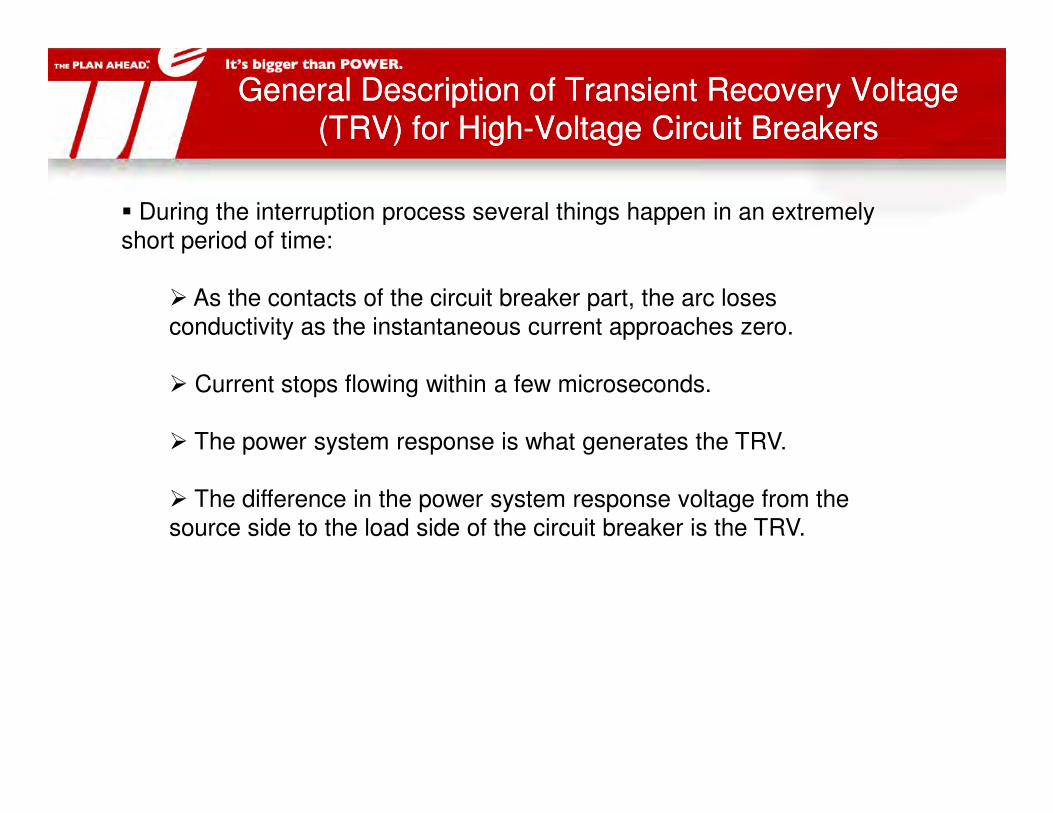
� During the interruption process several things happen in an extremely short period of time:
� As the contacts of the circuit breaker part, the arc loses conductivity as the instantaneous current approaches zero.
� Current stops flowing within a few microseconds.
� The power system response is what generates the TRV.
� The difference in the power system response voltage from the source side to the load side of the circuit breaker is the TRV.

General Description of Transient Recovery Voltage (TRV) for High-Voltage Circuit Breakers
General Description of Transient Recovery Voltage (TRV) for High-Voltage Circuit Breakers
When interrupting a fault at the circuit breaker terminals the supply voltage at the current zero is maximum and the supply side terminal reaches the supply voltage in a transient process called transient recovery voltage.
General Description of Transient Recovery Voltage (TRV) for High-Voltage Circuit Breakers
General Description of Transient Recovery Voltage (TRV) for High-Voltage Circuit Breakers
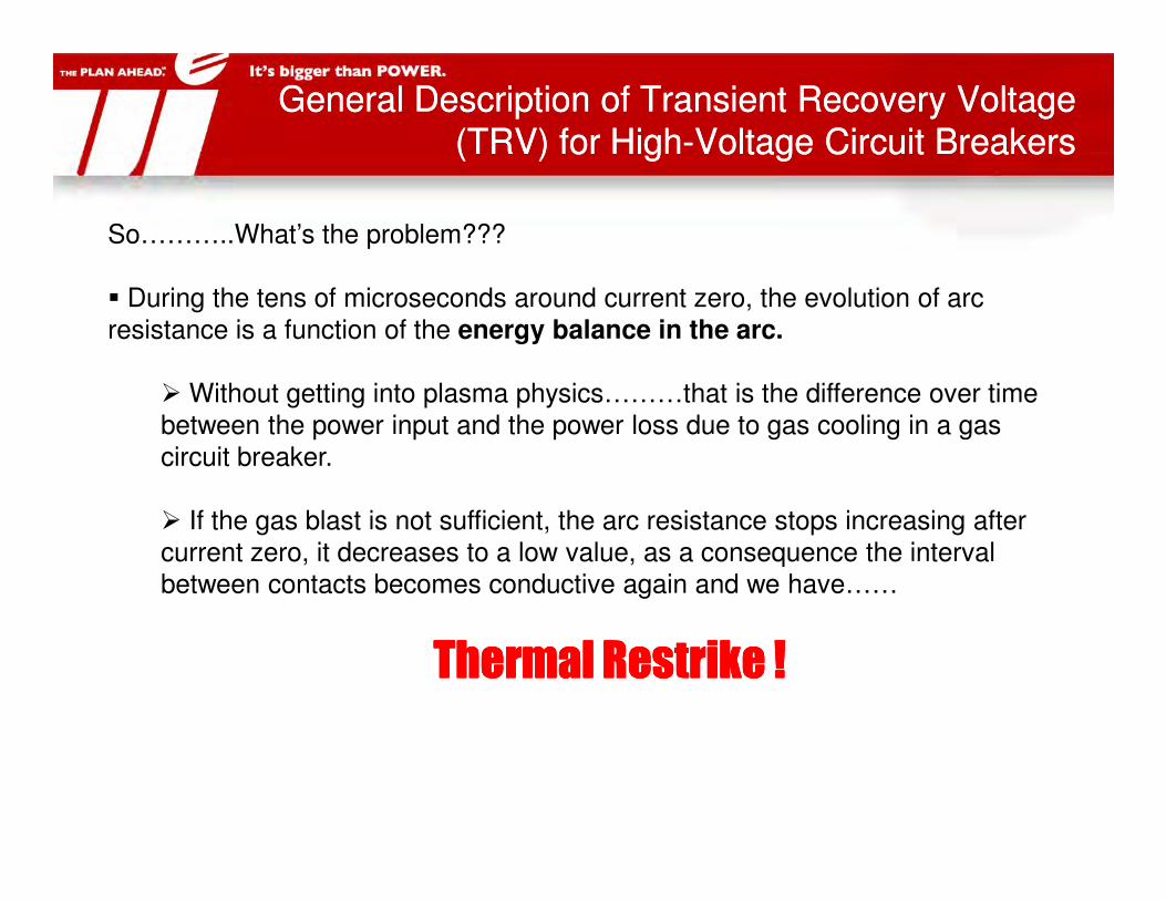
So………..What’s the problem???
� During the tens of microseconds around current zero, the evolution of arc resistance is a function of the energy balance in the arc.
� Without getting into plasma physics………that is the difference over time between the power input and the power loss due to gas cooling in a gas circuit breaker.circuit breaker.
� If the gas blast is not sufficient, the arc resistance stops increasing after current zero, it decreases to a low value, as a consequence the interval between contacts becomes conductive again and we have……
Thermal Restrike !Thermal Restrike !Thermal Restrike !Thermal Restrike !

IntroductionIntroduction
� Recent failures of transmission capacitor banks documented at theHydro One Richview Transformer Station.
� The UI transmission network consists of 115-kV overhead lines andunderground cables. The network employs two switched capacitorbanks at East Shore Substation for voltage and reactive power support.These capacitor banks are equipped with current limiting reactorsinstalled on the source side of the capacitor terminals.installed on the source side of the capacitor terminals.
� Based on the study, it was determined that existing 123kV, 50 kAcapacitor breakers do not possess sufficient TRV capabilities forclearing a three-phase ungrounded fault at the source-side terminals ofthe energized capacitor bank.
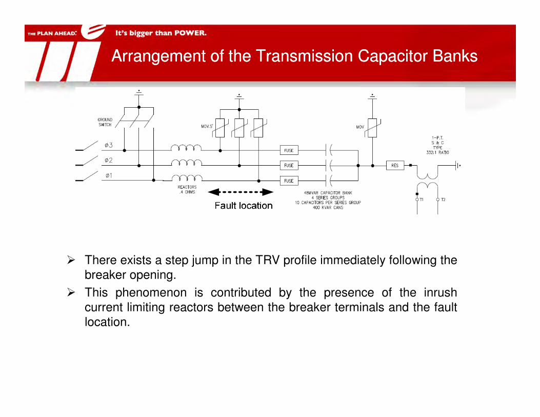
Arrangement of the Transmission Capacitor BanksArrangement of the Transmission Capacitor Banks
� There exists a step jump in the TRV profile immediately following thebreaker opening.
� This phenomenon is contributed by the presence of the inrushcurrent limiting reactors between the breaker terminals and the faultlocation.

Evaluation and Solution MethodsEvaluation and Solution Methods
� TRV withstand capabilities of a circuit breaker are evaluated usingstandard practices described in IEEE Std. C37.011-2005
� The most severe system TRVs tend to occur across the first pole toopen when the circuit breaker interrupts a symmetrical three-phaseungrounded fault at or near the breaker terminals during which thesystem voltage is at maximum.
� When a close-in line or bus fault occurs near an energized capacitor� When a close-in line or bus fault occurs near an energized capacitorbank, capacitive current will flow from the bank to the fault location.
� Circuit breakers will fail to close or open when inrush or outrushcurrents exceed the capacitive current switching duties of thebreakers.
� Current limiting reactors are usually required to limit the magnitudeand frequency of the capacitive switching current to an acceptablelevel.

Evaluation and Solution MethodsEvaluation and Solution Methods
The following criteria must be satisfied:
� The capacitor bank circuit breakers must be able to withstandtransient recovery voltage resulting from a three-phase ungroundedfault at the source-side of the capacitor terminals.
� The capacitor circuit switchers or breakers used to energize andde-energize capacitor banks must be able to withstand inrushde-energize capacitor banks must be able to withstand inrushcapacitive switching and momentary currents during back-to-backcapacitor switching.
� The line breakers must be able to withstand outrush capacitiveswitching and momentary currents during close-in faults.
Time Domain Model of the Electrical CircuitTime Domain Model of the Electrical Circuit
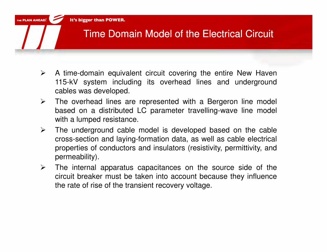
� A time-domain equivalent circuit covering the entire New Haven115-kV system including its overhead lines and undergroundcables was developed.
� The overhead lines are represented with a Bergeron line modelbased on a distributed LC parameter travelling-wave line modelwith a lumped resistance.
� The underground cable model is developed based on the cable� The underground cable model is developed based on the cablecross-section and laying-formation data, as well as cable electricalproperties of conductors and insulators (resistivity, permittivity, andpermeability).
� The internal apparatus capacitances on the source side of thecircuit breaker must be taken into account because they influencethe rate of rise of the transient recovery voltage.

TRV Analysis for the Existing ConditionTRV Analysis for the Existing Condition
� TRV capabilities of existing capacitor breakers were evaluated for the most conservative conditions.
� A three-phase ungrounded fault was applied at the source side of the energized capacitor and the other capacitor was offline. the other capacitor was offline.
TRV Analysis for the Existing ConditionTRV Analysis for the Existing Condition
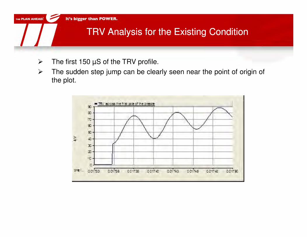
� The first 150 µS of the TRV profile.
� The sudden step jump can be clearly seen near the point of origin ofthe plot.

TRV Analysis for the Existing ConditionTRV Analysis for the Existing Condition
Comparison between the prospective system TRV associated with the capacitor breaker and the related TRV capability of a general
purpose breaker at 71% of interrupting rating.

Solution to the Initial Step Change in TRVSolution to the Initial Step Change in TRV
� A sound engineering solution to this problem is to relocate thesereactors to the neutral side of the capacitor bank.
� With this solution, an appropriately sized reactor for each phasecan be used for current limiting purposes without causing an initialstep change in the system TRV. Note that this solution alone willnot reduce the peak of the TRV profile.

Solution to the Initial Step Change in TRVSolution to the Initial Step Change in TRV
� The voltage step change between before and after the first pole opening is negligible. For this reason, the system TRV does not experience an initial step jump immediately after the first pole opening.
� The peak TRV exceeds the � The peak TRV exceeds the breaker withstand capability; however, the initial step jump in the system TRV is clearly eliminated.

Methods to Reduce the Rate of Rise and Peak TRVMethods to Reduce the Rate of Rise and Peak TRV
There are three basic approaches to reduce the rate of rise and thepeak value of the transient recovery voltage:
� Approach 1. Provide additional capacitances to the source side ofthe capacitor circuit breakers without modifying the configuration ofexisting capacitor banks. Additional capacitances can be in theform of bushing capacitances, capacitive voltage transformers, andform of bushing capacitances, capacitive voltage transformers, andcapacitance banks.
� Approach 2: Modify the existing capacitor configuration in such away to reduce the rate of rise and peak value of the system TRV.This approach includes replacing existing capacitor breakers withthose having higher TRV duties and providing an intentional groundto the neutral of the capacitor bank configuration.
� Approach 3: Combine the above two approaches.
Methods to Reduce the Rate of Rise and Peak TRVMethods to Reduce the Rate of Rise and Peak TRV
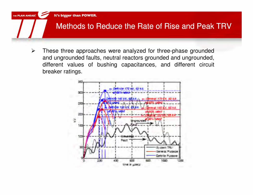
� These three approaches were analyzed for three-phase groundedand ungrounded faults, neutral reactors grounded and ungrounded,different values of bushing capacitances, and different circuitbreaker ratings.
Recommended Capacitor ConfigurationRecommended Capacitor Configuration
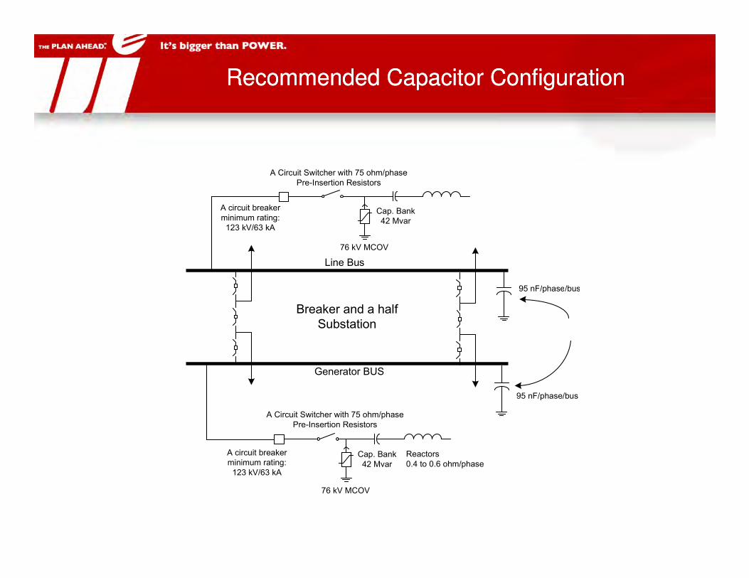
Line Bus
95 nF/phase/bus
Cap. Bank
42 Mvar
76 kV MCOV
A circuit breaker
minimum rating:
123 kV/63 kA
A Circuit Switcher with 75 ohm/phase
Pre-Insertion Resistors
Generator BUS
Breaker and a half
Substation
95 nF/phase/bus
95 nF/phase/bus
A circuit breaker
minimum rating:
123 kV/63 kA
Cap. Bank
42 Mvar
Reactors
0.4 to 0.6 ohm/phase
76 kV MCOV
A Circuit Switcher with 75 ohm/phase
Pre-Insertion Resistors

Paper on Methods to Reduce the Rate of Rise and Peak TRVPaper on Methods to Reduce the Rate of Rise and Peak TRV

General Description of Transient Recovery Voltage (TRV) for High-Voltage Circuit Breakers
General Description of Transient Recovery Voltage (TRV) for High-Voltage Circuit Breakers
This is true of air-insulated systems and single phase gas-insulated systems.
So why did we care about this at Grand Avenue?
Initial proposal was to use a 3-phase in one enclosure design
In a 3-phase in one enclosure design a single phase to ground fault inside the enclosure will evolve to a 3-phase ungrounded fault in a few milliseconds, due to the rapid breakdown of the dielectric distance between the three phases, which is then causes the single phase to ground fault to extinguish.

General Description of Transient Recovery Voltage (TRV) for High-Voltage Circuit Breakers
General Description of Transient Recovery Voltage (TRV) for High-Voltage Circuit Breakers

Grand Avenue CircuitsGrand Avenue Circuits
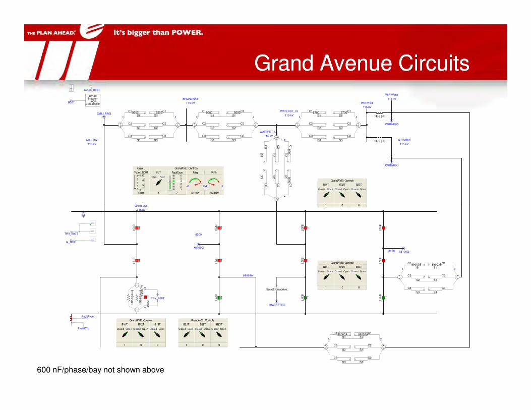
Grand Avenue CircuitsGrand Avenue Circuits
Grand Ave
W.RIVR88
115 kV
WATERST_UI
115 kV
W.RIVR89
115 kV
W.RIVR 8
115 kV
BROADWAY
115 kV
XWRIV89G
XWRIV88G
1E-9 [H]
1E-9 [H]
XMILLRIVG
C1
85
00S
1
C2
S2
C3
S3
C1
85
00
S1
C2
S2
C3
S3
C18700
S1
C2
S2
C3
S3
C18700
S1
C2
S2
C3
S3
C19502
S1
C2
S2
C3
S3
C19502
S1
C2
S2
C3
S3
C19500
S1
C2
S2
C3
S3
C19500
S1
C2
S2
C3
S3MILL RIV
115 kV
WATERST_UI
115 kV
Gran...
0.99
0
Topen_B00T
0.081
B00T
TimedBreaker
LogicClosed@t0
Topen_B00T
GrandAVE : Controls
FLT
1
Clear Fault654321
FaultType
7
Mag
43.9423
IAPh
-85.4422
GrandAVE : Controls
B31T
1
Closed Open
B32T
0
Closed Open
B33T
0
Closed Open
Grand Ave
115 kV
X8100G
FaultType
FaultCTL
Sackett-GrandAveT
XSACKETTG
Ea
C189003B
S1
C2
S2
C3
S3
C189003B
S1
C2
S2
C3
S3B2
1T
B4
3T
B2
2T
B1
3T
B1
2T
GrandAVE : Controls
B11T
1
Closed Open
B12T
0
Closed Open
B13T
0
Closed Open
GrandAVE : Controls
B21T
1
Closed Open
B22T
0
Closed Open
B23T
0
Closed Open
B3
1T
B3
2T
B2
3T
8200
B4
1T
B4
2T
B3
3T
GrandAVE : Controls
B41T
1
Closed Open
B42T
0
Closed Open
B43T
0
Closed Open
8100
88003A
C188003A
S1
C2
S2
C3
S3
C188003AS1
C2
S2
C3
S3
X8200G
Ia_
B0
0T
B0
0T1
.0E
-6 [o
hm
]
1.0
E-6
[o
hm
]
TRV_B00T
TRV_B00T
Ia_B00T
1 0 0
600 nF/phase/bay not shown above

Evaluation of Breaker B11 (-11T-2)Evaluation of Breaker B11 (-11T-2)
General fault conditions:
• A three-phase ungrounded fault
is applied at a bus (i.e. ‘A’ or ‘B’ bus).
• The evaluated breaker is the last to trip – all bus breakers on the faulted bus have tripped.
System Transient Recovery Voltage
0
50
100
150
200
250
300
kV
TRV_B00T System TRV seen by B11
• East Shore, Sackett, and North Haven 115 kV capacitors are offline.
Evaluation for Breaker B11
• A three-phase ungrounded fault at ‘A’ Bus
• B21, B31, B41 have tripped.
• B11 is the last to trip.
second 0.0070 0.0080 0.0090 0.0100 ... ... ...
-50
0
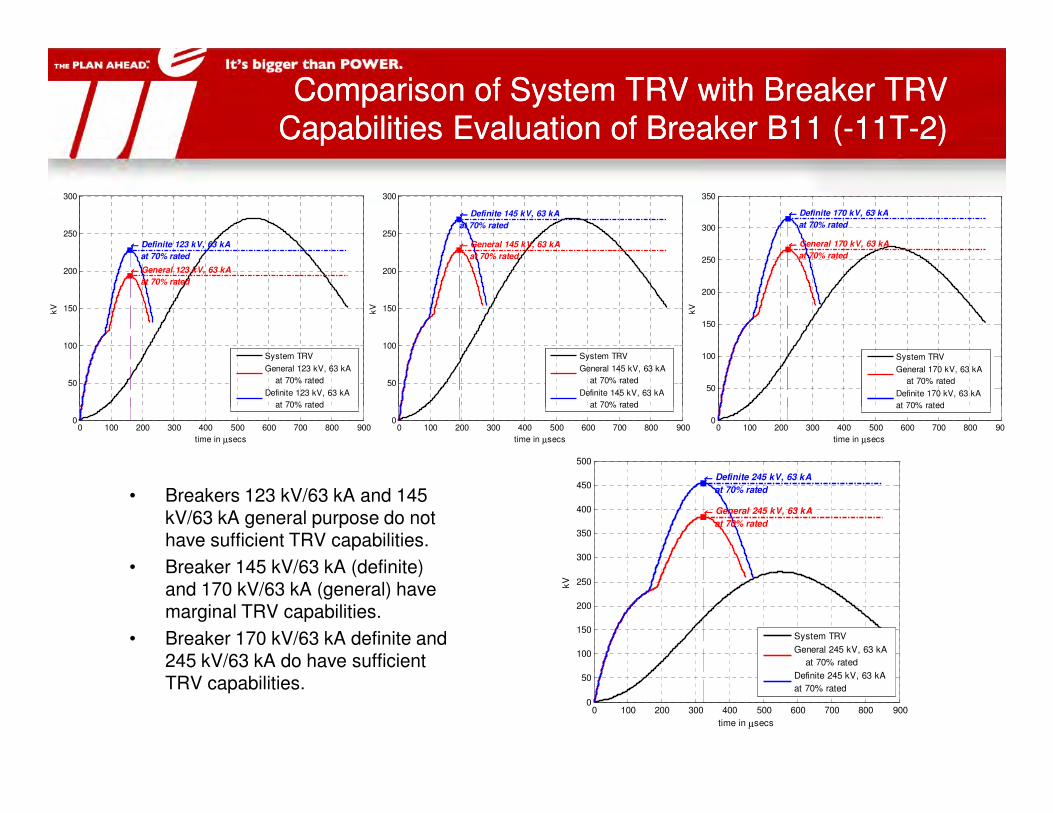
Comparison of System TRV with Breaker TRV Capabilities Evaluation of Breaker B11 (-11T-2)Comparison of System TRV with Breaker TRV
Capabilities Evaluation of Breaker B11 (-11T-2)
50
100
150
200
250
300
←←←← General 123 kV, 63 kA
at 70% rated
←←←← Definite 123 kV, 63 kA
at 70% rated
kV
System TRV
General 123 kV, 63 kA
at 70% rated
Definite 123 kV, 63 kA
at 70% rated
50
100
150
200
250
300
←←←← General 145 kV, 63 kA
at 70% rated
←←←← Definite 145 kV, 63 kA
at 70% rated
kV
System TRV
General 145 kV, 63 kA
at 70% rated
Definite 145 kV, 63 kA
at 70% rated
50
100
150
200
250
300
350
←←←← General 170 kV, 63 kA
at 70% rated
←←←← Definite 170 kV, 63 kA
at 70% rated
kV
System TRV
General 170 kV, 63 kA
at 70% rated
Definite 170 kV, 63 kA
at 70% rated
• Breakers 123 kV/63 kA and 145 kV/63 kA general purpose do not have sufficient TRV capabilities.
• Breaker 145 kV/63 kA (definite) and 170 kV/63 kA (general) have marginal TRV capabilities.
• Breaker 170 kV/63 kA definite and 245 kV/63 kA do have sufficient TRV capabilities.
0 100 200 300 400 500 600 700 800 9000
time in µsecs
at 70% rated
0 100 200 300 400 500 600 700 800 9000
time in µsecs
at 70% rated
0 100 200 300 400 500 600 700 800 9000
time in µsecs
at 70% rated
0 100 200 300 400 500 600 700 800 9000
50
100
150
200
250
300
350
400
450
500
←←←← General 245 kV, 63 kA
at 70% rated
←←←← Definite 245 kV, 63 kA
at 70% rated
time in µsecs
kV
System TRV
General 245 kV, 63 kA
at 70% rated
Definite 245 kV, 63 kA
at 70% rated

Evaluation of Breaker B21, B31, B41Evaluation of Breaker B21, B31, B41
Evaluation for Breaker B21, B31, and B41
• A three-phase ungrounded fault at ‘A’ Bus
• The evaluated breaker is the last to trip;all bus breakers on the faulted bus have tripped
• East Shore, Sackett, and North Haven 115 kV capacitors are offline.
Results for Breaker B21 B31, and B41
• They are identical to B11 results.100
150
200
250
300
350
←←←← General 170 kV, 63 kA
at 70% rated
←←←← Definite 170 kV, 63 kA
at 70% rated
kV
←←←← General 123 kV, 63 kA
at 70% rated
←←←← Definite 123 kV, 63 kA
at 70% rated
• They are identical to B11 results.
• See slide 5.
• Marginal ratings: 170 kV, 63 kA general purpose
• Desired ratings: 170 kV, 63 kA definite purpose
GrandAVE : Graphs
second 0.0065 0.0070 0.0075 0.0080 0.0085 0.0090 0.0095 0.0100 ... ... ...
-50
0
50
100
150
200
250
300
kVTRV_B00T
0 100 200 300 400 500 600 700 800 9000
50
time in µsecs
System TRV
General Purpose
Definite Purpose

Evaluation of Breaker B13, B23, B33, B43Evaluation of Breaker B13, B23, B33, B43
Evaluation for Breaker B13, B23, B33, B43
• A three-phase ungrounded fault at B’ Bus
• The evaluated breaker is the last to trip;all bus breakers on the faulted bus have tripped
• East Shore, Sackett, and North Haven 115 kV capacitors are offline.
Results for Breaker B13 B23, B33, and B43
• They are identical to B11 results. 100
150
200
250
300
350
←←←← General 170 kV, 63 kA
at 70% rated
←←←← Definite 170 kV, 63 kA
at 70% rated
kV
←←←← General 123 kV, 63 kA
at 70% rated
←←←← Definite 123 kV, 63 kA
at 70% rated
• They are identical to B11 results.
• See slide 5.
• Marginal ratings: 170 kV, 63 kA general purpose
• Desired ratings: 170 kV, 63 kA definite purpose
GrandAVE : Graphs
second 0.0065 0.0070 0.0075 0.0080 0.0085 0.0090 0.0095 0.0100 ... ... ...
-50
0
50
100
150
200
250
300
kVTRV_B00T
0 100 200 300 400 500 600 700 800 9000
50
100
time in µsecs
System TRV
General Purpose
Definite Purpose

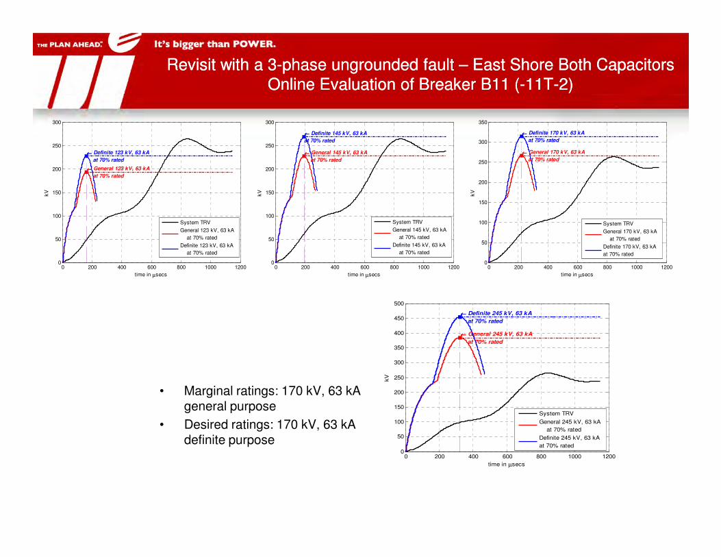
Revisit with a 3-phase ungrounded fault – East Shore Both Capacitors Online Evaluation of Breaker B11 (-11T-2)
Revisit with a 3-phase ungrounded fault – East Shore Both Capacitors Online Evaluation of Breaker B11 (-11T-2)
General fault conditions:
• A three-phase ungrounded fault
is applied at a bus (i.e. ‘A’ or ‘B’ bus).
• The evaluated breaker is the last to trip – all bus breakers on the faulted bus have tripped.
• Both East Shore 115 kV capacitors are online.
System TRV seen by B11
25
50
75
100
125
150
175
200
225
kV
TRV_B00T
Evaluation for Breaker B11
• A three-phase ungrounded fault at ‘A’ Bus
• B21, B31, B41 have tripped.
• B11 is the last to trip.
second 0.0070 0.0080 0.0090 0.0100 ... ... ...
0
25
Revisit with a 3-phase ungrounded fault – East Shore Both Capacitors Online Evaluation of Breaker B11 (-11T-2)
Revisit with a 3-phase ungrounded fault – East Shore Both Capacitors Online Evaluation of Breaker B11 (-11T-2)
0 200 400 600 800 1000 12000
50
100
150
200
250
300
←←←← General 123 kV, 63 kA
at 70% rated
←←←← Definite 123 kV, 63 kA
at 70% rated
time in µsecs
kV
System TRV
General 123 kV, 63 kA
at 70% rated
Definite 123 kV, 63 kA
at 70% rated
0 200 400 600 800 1000 12000
50
100
150
200
250
300
←←←← General 145 kV, 63 kA
at 70% rated
←←←← Definite 145 kV, 63 kA
at 70% rated
time in µsecs
kV
System TRV
General 145 kV, 63 kA
at 70% rated
Definite 145 kV, 63 kA
at 70% rated
0 200 400 600 800 1000 12000
50
100
150
200
250
300
350
←←←← General 170 kV, 63 kA
at 70% rated
←←←← Definite 170 kV, 63 kA
at 70% rated
time in µsecs
kV
System TRV
General 170 kV, 63 kA
at 70% rated
Definite 170 kV, 63 kA
at 70% rated
• Marginal ratings: 170 kV, 63 kA general purpose
• Desired ratings: 170 kV, 63 kA definite purpose
0 200 400 600 800 1000 12000
50
100
150
200
250
300
350
400
450
500
←←←← General 245 kV, 63 kA
at 70% rated
←←←← Definite 245 kV, 63 kA
at 70% rated
time in µsecs
kV
System TRV
General 245 kV, 63 kA
at 70% rated
Definite 245 kV, 63 kA
at 70% rated

Remarks/ConclusionRemarks/Conclusion
• Breaker ratings based on three-phase ungrounded faults.
– Bus breakers for Grand Avenue must be rated at minimum 170 kV/63 kA with definite purpose duty.
• We chose to apply 245kV/63kA equipment to satisfy the TRV rating requirements and to use general purpose TRV rating requirements and to use general purpose breakers.

Questions?Questions?
??


