Energy Efficient Buildings Evaporative Cooling Examples of evaporative cooling include: Boiling water Evaporation from body Evaporation from lakes and oceans Roof ponds Roof misting Swimming pools Cooling towers The energy transferred during evaporation is so great, that it can effectively cool buildings using relatively little energy. A typical residential-size evaporative cooler is shown below. In this unit, a fan pulls outdoor air through the sides of the unit and forces it into a duct that leads into the conditioned space. Water from the “water tank” in the bottom of the unit is pumped to the top of the unit and falls through fibrous mats called “evaporative pads” that line three sides of the unit. As outdoor air is pulled through the wet “evaporative pads”, it evaporates some of the water and leaves at a lower temperature and higher humidity. These units are sometimes called “swamp coolers” and are widely used in hot dry climates, since they cool and humidify air using very little energy. 1
Transcript
Energy Efficient BuildingsEvaporative Cooling
Examples of evaporative cooling include:Boiling waterEvaporation from bodyEvaporation from lakes and oceansRoof pondsRoof mistingSwimming poolsCooling towers
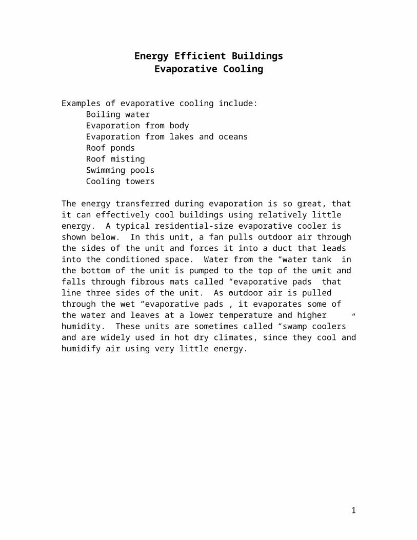
The energy transferred during evaporation is so great, that it can effectively cool buildings using relatively little energy. A typical residential-size evaporative cooler is shown below. In this unit, a fan pulls outdoor air through the sides of the unit and forces it into a duct that leads into the conditioned space. Water from the “water tank” in the bottom of the unit is pumped to the top of the unit and falls through fibrous mats called “evaporative pads” that line three sides of the unit. As outdoor air is pulled through the wet “evaporative pads”, it evaporates some of the water and leaves at a lower temperature and higher humidity. These units are sometimes called “swamp coolers” and are widely used in hot dry climates, since they cool and humidify air using very little energy.
1
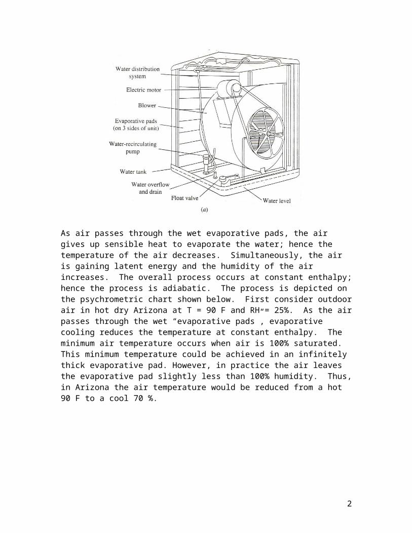
As air passes through the wet evaporative pads, the air gives up sensible heat to evaporate the water; hence the temperature of the air decreases. Simultaneously, the air is gaining latent energy and the humidity of the air increases. The overall process occurs at constant enthalpy; hence the process is adiabatic. The process is depicted on the psychrometric chart shown below. First consider outdoor air in hot dry Arizona at T = 90 F and RH = 25%. As the air passes through the wet “evaporative pads”, evaporative cooling reduces the temperature at constant enthalpy. The minimum air temperature occurs when air is 100% saturated. This minimum temperature could be achieved in an infinitely thick evaporative pad. However, in practice the air leaves the evaporative pad slightly less than 100% humidity. Thus, in Arizona the air temperature would be reduced from a hot 90 F to a cool 70 %.
Next consider outdoor air in hot, humid Mississippi T = 90 F and RH = 70%. As the air passes through the wet “evaporative pads”, evaporative cooling reduces the temperature at constant enthalpy. The minimum air temperature would occur at about 82 F, and the actual leaving air temperature would be even higher. Thus, the cooling potential of evaporative coolers is much greater in dry climates.
The performance of evaporative coolers can be modeled using the concept of effectiveness. We define effectiveness as:
ε=Δ Tactual
ΔTmax=T 1 - T2,act
T 1 - Twb,1
2
Most coolers about 80% effective. In Arizona example shown above, the effectiveness is:
ε=T1 - T2,act
T1 - Twb,1=90−70
90 - 65=80 %
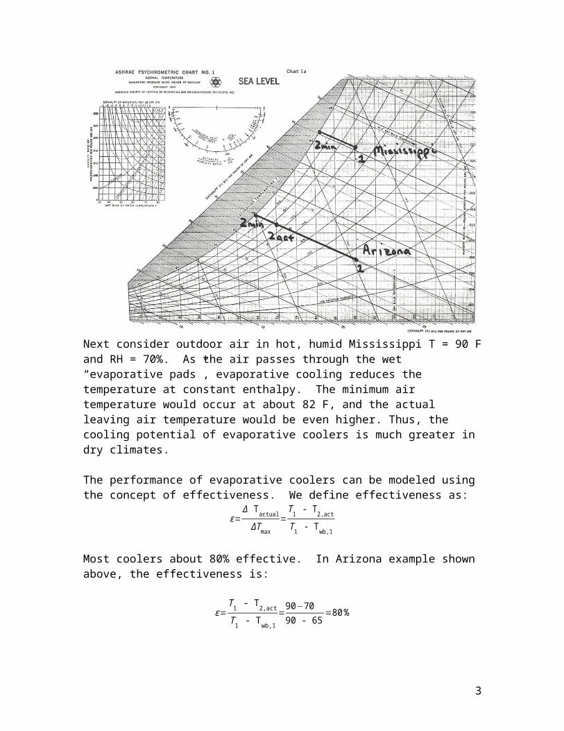
The effectiveness concept shows that that lowest possible temperature of the air exiting the cooler is entering air wet-bulb temperature. Thus, wet-bulb temperature can be used to as guide to the effectiveness of evaporative coolers. The chart below shows 95% design wet-bulb temperatures in the U.S. The graph shows that practically the entire western part of the U.S. has design wet-bulb temperatures less than 70 F. This suggests that evaporative coolers could regularly cool air to less than 70 F over most of the western U.S., and do so using much less energy than vapor compression air conditioners and chillers.
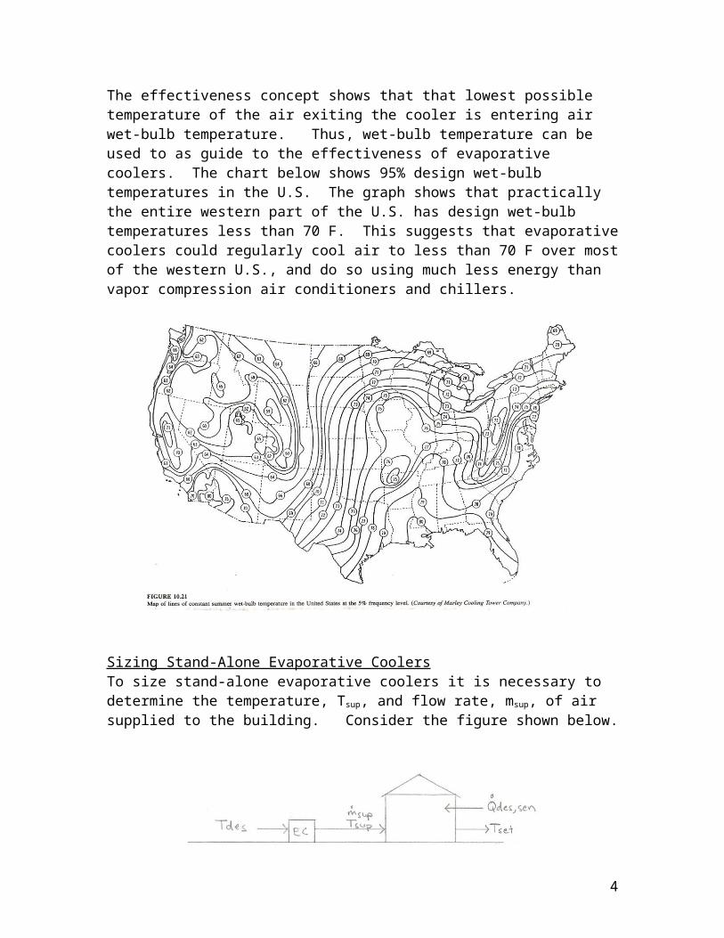
Sizing Stand-Alone Evaporative CoolersTo size stand-alone evaporative coolers it is necessary to determine the temperature, Tsup, and flow rate, msup, of air supplied to the building. Consider the figure shown below.
3
The first step is to solve for Tsup at design conditions.
ε=Δ Tactual
ΔT max=Tdes - T sup
Tdes - Tdes,wbT sup= Tdes - ε (T des - Tdes,wb )
If Tsup < Tset, then evaporative cooler can provide cooling.
The second step is to determine the flow rate of air at design conditions, msup, from an energy balance on the house. Consider only the sensible heat load since an evaporative cooler is incapable of removing moisture.
msup c p Tsup+ Qdes,sen= m sup cp Tset
msup=Qdes,sen
c p(T sen - Tsup )
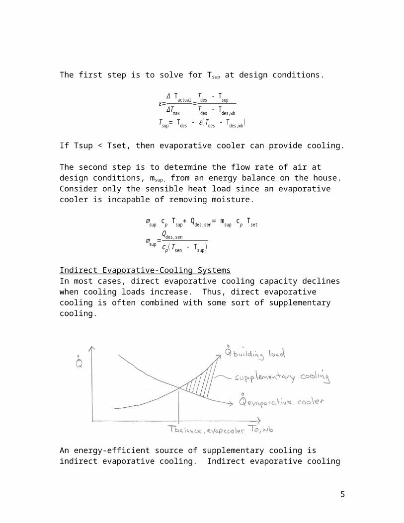
Indirect Evaporative-Cooling SystemsIn most cases, direct evaporative cooling capacity declines when cooling loads increase. Thus, direct evaporative cooling is often combined with some sort of supplementary cooling.
An energy-efficient source of supplementary cooling is indirect evaporative cooling. Indirect evaporative cooling systems use water from a cooling tower to cool air through
4
a heat exchanger. The word “indirect” refers to the fact that the cooling water does not come into direct contact with the supply air to the building. To understand, indirect evaporative cooling it is necessary to understand cooling tower performance.
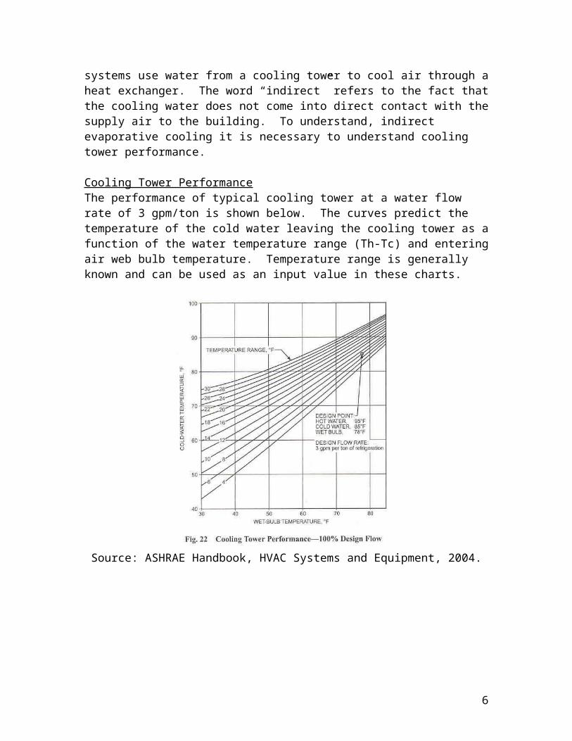
Cooling Tower PerformanceThe performance of typical cooling tower at a water flow rate of 3 gpm/ton is shown below. The curves predict the temperature of the cold water leaving the cooling tower as a function of the water temperature range (Th-Tc) and entering air web bulb temperature. Temperature range is generally known and can be used as an input value in these charts.
Source: ASHRAE Handbook, HVAC Systems and Equipment, 2004.
5
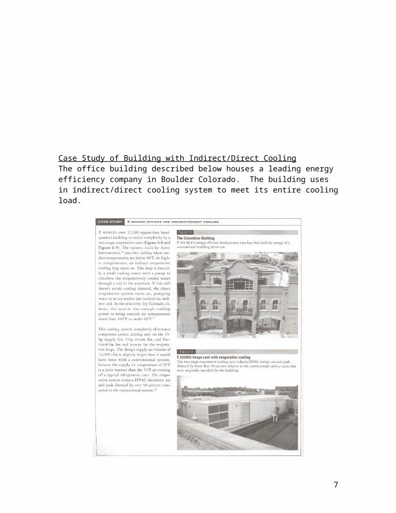
Case Study of Building with Indirect/Direct CoolingThe office building described below houses a leading energy efficiency company in Boulder Colorado. The building uses in indirect/direct cooling system to meet its entire cooling load.
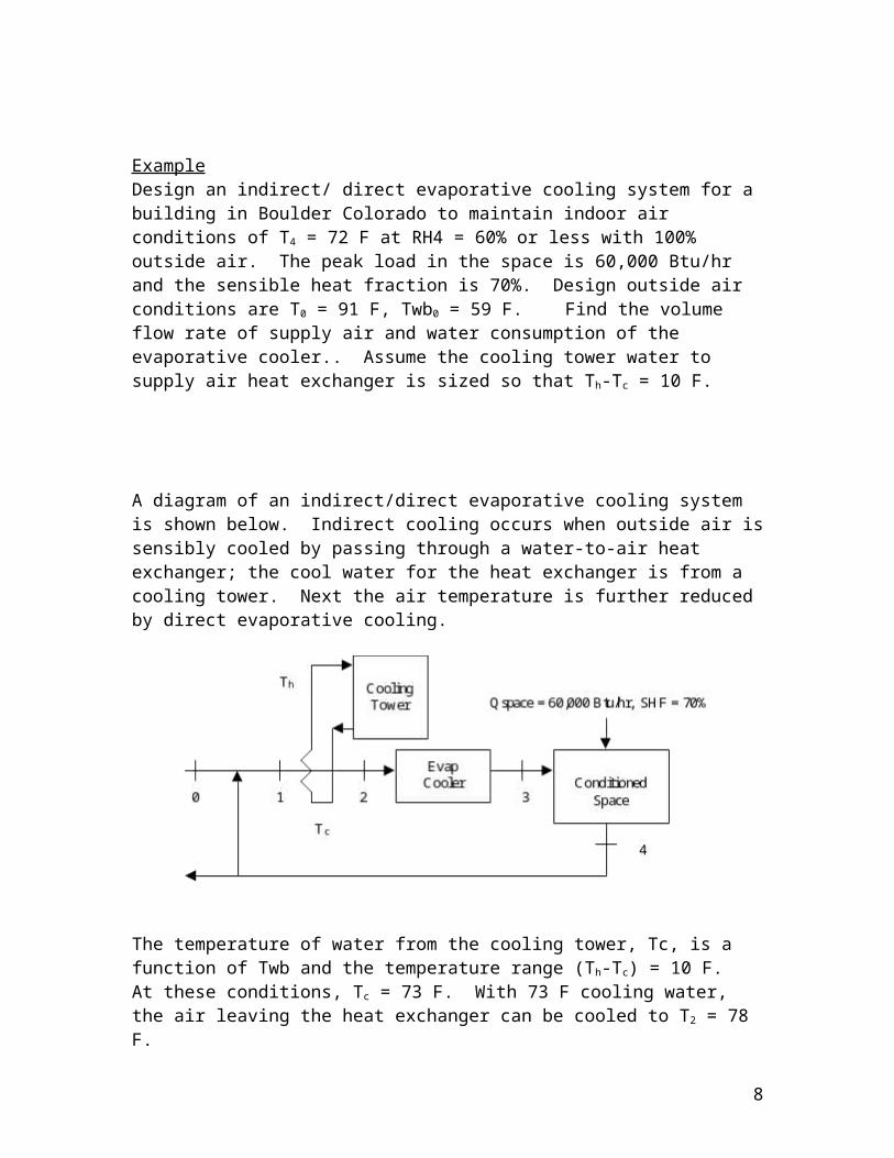
ExampleDesign an indirect/ direct evaporative cooling system for a building in Boulder Colorado to maintain indoor air conditions of T4 = 72 F at RH4 = 60% or less with 100% outside air. The peak load in the space is 60,000 Btu/hr and the sensible heat fraction is 70%. Design outside air conditions are T0 = 91 F, Twb0 = 59 F. Find the volume flow rate of supply air and water consumption of the evaporative cooler.. Assume the cooling tower water to supply air heat exchanger is sized so that Th-Tc = 10 F.
6
A diagram of an indirect/direct evaporative cooling system is shown below. Indirect cooling occurs when outside air is sensibly cooled by passing through a water-to-air heat exchanger; the cool water for the heat exchanger is from a cooling tower. Next the air temperature is further reduced by direct evaporative cooling.
The temperature of water from the cooling tower, Tc, is a function of Twb and the temperature range (Th-Tc) = 10 F. At these conditions, Tc = 73 F. With 73 F cooling water, the air leaving the heat exchanger can be cooled to T2 = 78 F.
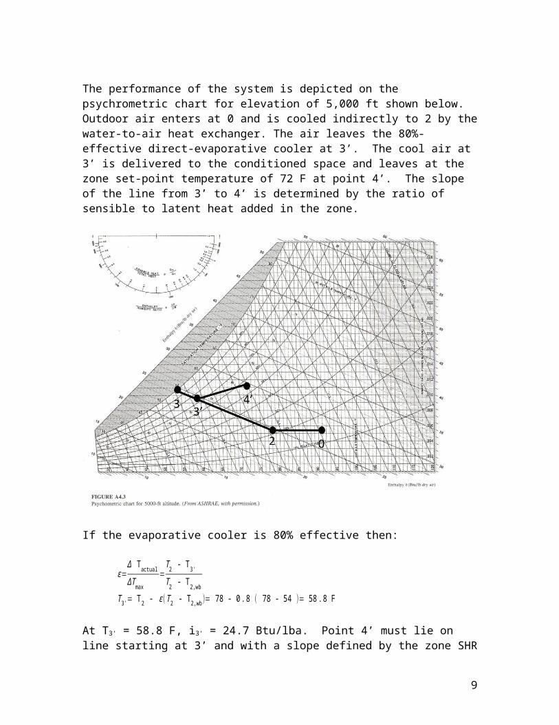
The performance of the system is depicted on the psychrometric chart for elevation of 5,000 ft shown below. Outdoor air enters at 0 and is cooled indirectly to 2 by the water-to-air heat exchanger. The air leaves the 80%-effective direct-evaporative cooler at 3’. The cool air at 3’ is delivered to the conditioned space and leaves at the zone set-point temperature of 72 F at point 4’. The slope of the line from 3’ to 4’ is determined by the ratio of sensible to latent heat added in the zone.
At T3' = 58.8 F, i3' = 24.7 Btu/lba. Point 4’ must lie on line starting at 3’ and with a slope defined by the zone SHR = 0.70. The enthalpy at 4’ is i4' = 29.6 Btu/lba. An energy balance on space gives:


![PASSIVE DOWNDRAUGHT EVAPORATIVE COOLING: The … · can be used to achieve thermal comfort. [1] Passive Downdraught Evaporative cooling (PDEC) Origin: Evaporative cooling has been](https://static.documents.pub/doc/80x56/5f835db0418ed251ad1ae1c3/passive-downdraught-evaporative-cooling-the-can-be-used-to-achieve-thermal-comfort.jpg)


