EVEN HARMONIC RESONANCE- AN UNUSUAL PROBLEM Copyright Material IEEE Paper No. PCIC 2002-11 Paul C. Buddingh, P.Eng. Member, IEEE Universal Dynamics Limited 100 – 13700 International Place Richmond, BC V6V 2X8 Canada Abstract - The paper is a case study examining the cause, effect and solution of an actual “non-characteristic” even harmonic problem in an electrochemical plant. While issues concerning “characteristic” harmonics are well documented in the literature, limited information is available describing how non-characteristic harmonic currents create operational problems. The author has not found any papers describing a case of even harmonic resonance and would like to share the experience of resolving a 4 th harmonic resonance problem in the hopes it will benefit others. Index Terms – Harmonics, characteristic, non-characteristic odd even, resonance, harmonic instability. I. INTRODUCTION This case study describes an investigation by the author of harmonic filter failures at a Chemical plant in North America. The plant utilizes large static converters to take incoming High Voltage low current 60 Hz, AC power and rectify it into to Low Voltage, very high current DC power for operation of the electrochemical cells. Harmonic current generation is expected in this type of power system and harmonic filters are commonly used to limit harmonic levels and protect power system components. A call from the plant indicated that they were experiencing what appeared to be overheating of a set of reactors used in a harmonic filter associated with one of the plant’s converter systems. The reactors in the 5 th harmonic branch of the filter had discolored, and dark bands were evident on the glass- fiber surface of the reactors. The filter was originally installed in 1988 and had a history of problems. The 5 th harmonic reactors had failed before, and a clear cause was never identified. As historical information was reviewed and measurement data collected, it became apparent that something unusual was occurring. This paper outlines the power and harmonic filter systems at the plant, discusses how uncharacteristic harmonics are generated, analyzes the difficulty, identifies the cause and provides an action plan used to correct the problem. II. POWER SYSTEM CONFIGURATION The plant has two production lines, Lines A and B, each consisting of a series of electrochemical cells. Line A consists of a 1978 vintage 6-pulse rectifier in a single-way ANSI 45 configuration with inter-phase transformer. The primary voltage is 13.8 kV. Each of the 6 phases or “legs” has eight parallel thyristors. A phase lock Fig. 1: Line A Harmonic Filter loop (PLL) type control system using discrete analog electronics is implemented. A three-branch harmonic filter is installed, consisting of branches tuned precisely to the 5 th , 7 th and 11 th harmonic with 6.9 effective MVAR of capacitors. The Line B rectifier system is supplied directly at 66 kV, in an ANSI 45/46 12-pulse configuration shifted an extra 15° apart to make a 24-pulse system. The rectifiers are equipped with a single branch harmonic filter, also at 66 kV, tuned at the 4.7 th harmonic and rated at 15 MVAR effective. III. BACKGROUND It has been well known, since at least the 1930’s, that rectifiers produce harmonic currents as they convert electric power from AC to DC. A classic paper from the days of the mercury arc rectifiers, still relevant today, was written in 1945 by J. C. Read. [1]. The proliferation of large thyristor rectifiers in the late 1960s and early 1970s created a resurgence and exacerbation of harmonics issues, largely a result of the increased size of the converters (in the 20 MW to 30 MW range). These new larger rectifiers typically required large capacitor banks for power factor correction, creating an ideal environment for parallel resonance disturbances. In response, a number of excellent papers were produced addressing this new twist on an old problem [2] [3]. 1
Transcript
EVEN HARMONIC RESONANCE- AN UNUSUAL PROBLEM
Copyright Material IEEE Paper No. PCIC 2002-11
Paul C. Buddingh, P.Eng. Member, IEEE
Universal Dynamics Limited 100 – 13700 International Place
Richmond, BC V6V 2X8 Canada
Abstract - The paper is a case study examining the cause, effect and solution of an actual “non-characteristic” even harmonic problem in an electrochemical plant. While issues concerning “characteristic” harmonics are well documented in the literature, limited information is available describing how non-characteristic harmonic currents create operational problems. The author has not found any papers describing a case of even harmonic resonance and would like to share the experience of resolving a 4th harmonic resonance problem in the hopes it will benefit others.
This case study describes an investigation by the author of harmonic filter failures at a Chemical plant in North America. The plant utilizes large static converters to take incoming High Voltage low current 60 Hz, AC power and rectify it into to Low Voltage, very high current DC power for operation of the electrochemical cells. Harmonic current generation is expected in this type of power system and harmonic filters are commonly used to limit harmonic levels and protect power system components.
A call from the plant indicated that they were experiencing what appeared to be overheating of a set of reactors used in a harmonic filter associated with one of the plant’s converter systems. The reactors in the 5th harmonic branch of the filter had discolored, and dark bands were evident on the glass-fiber surface of the reactors.
The filter was originally installed in 1988 and had a history of problems. The 5th harmonic reactors had failed before, and a clear cause was never identified. As historical information was reviewed and measurement data collected, it became apparent that something unusual was occurring.
This paper outlines the power and harmonic filter systems at the plant, discusses how uncharacteristic harmonics are generated, analyzes the difficulty, identifies the cause and provides an action plan used to correct the problem.
II. POWER SYSTEM CONFIGURATION
The plant has two production lines, Lines A and B, each consisting of a series of electrochemical cells.
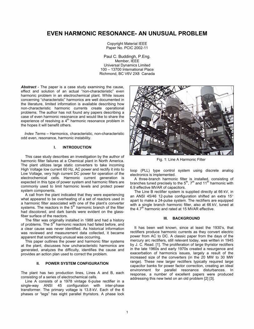
Line A consists of a 1978 vintage 6-pulse rectifier in a single-way ANSI 45 configuration with inter-phase transformer. The primary voltage is 13.8 kV. Each of the 6 phases or “legs” has eight parallel thyristors. A phase lock
Fig. 1: Line A Harmonic Filter
loop (PLL) type control system using discrete analog electronics is implemented.
A three-branch harmonic filter is installed, consisting of branches tuned precisely to the 5th, 7th and 11th harmonic with 6.9 effective MVAR of capacitors.
The Line B rectifier system is supplied directly at 66 kV, in an ANSI 45/46 12-pulse configuration shifted an extra 15° apart to make a 24-pulse system. The rectifiers are equipped with a single branch harmonic filter, also at 66 kV, tuned at the 4.7th harmonic and rated at 15 MVAR effective.
III. BACKGROUND
It has been well known, since at least the 1930’s, that rectifiers produce harmonic currents as they convert electric power from AC to DC. A classic paper from the days of the mercury arc rectifiers, still relevant today, was written in 1945 by J. C. Read. [1]. The proliferation of large thyristor rectifiers in the late 1960s and early 1970s created a resurgence and exacerbation of harmonics issues, largely a result of the increased size of the converters (in the 20 MW to 30 MW range). These new larger rectifiers typically required large capacitor banks for power factor correction, creating an ideal environment for parallel resonance disturbances. In response, a number of excellent papers were produced addressing this new twist on an old problem [2] [3].
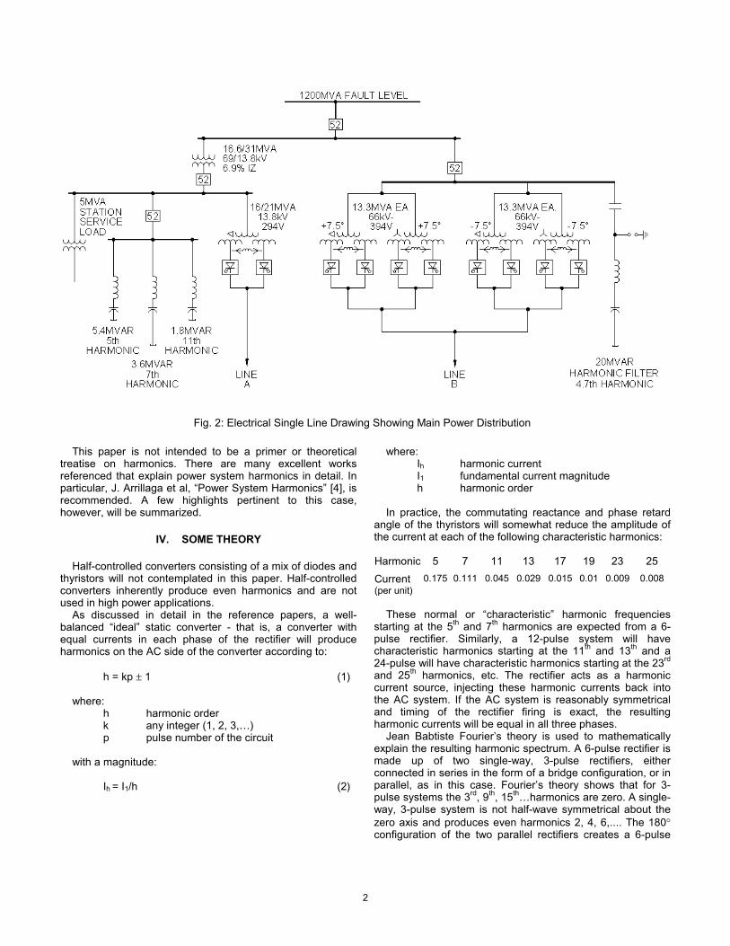
Fig. 2: Electrical Single Line Drawing Showing Main Power Distribution
This paper is not intended to be a primer or theoretical treatise on harmonics. There are many excellent works referenced that explain power system harmonics in detail. In particular, J. Arrillaga et al, “Power System Harmonics” [4], is recommended. A few highlights pertinent to this case, however, will be summarized.
IV. SOME THEORY
Half-controlled converters consisting of a mix of diodes and thyristors will not contemplated in this paper. Half-controlled converters inherently produce even harmonics and are not used in high power applications.
As discussed in detail in the reference papers, a well-balanced “ideal” static converter - that is, a converter with equal currents in each phase of the rectifier will produce harmonics on the AC side of the converter according to:
h = kp ± 1 (1)
where: h harmonic order k any integer (1, 2, 3,…) p pulse number of the circuit
with a magnitude:
Ih = I1/h (2)
where: Ih harmonic current I1 fundamental current magnitude h harmonic order
In practice, the commutating reactance and phase retard angle of the thyristors will somewhat reduce the amplitude of the current at each of the following characteristic harmonics:
These normal or “characteristic” harmonic frequencies starting at the 5th and 7th harmonics are expected from a 6-pulse rectifier. Similarly, a 12-pulse system will have characteristic harmonics starting at the 11th and 13th and a 24-pulse will have characteristic harmonics starting at the 23rd
and 25th harmonics, etc. The rectifier acts as a harmonic current source, injecting these harmonic currents back into the AC system. If the AC system is reasonably symmetrical and timing of the rectifier firing is exact, the resulting harmonic currents will be equal in all three phases.
Jean Babtiste Fourier’s theory is used to mathematically explain the resulting harmonic spectrum. A 6-pulse rectifier is made up of two single-way, 3-pulse rectifiers, either connected in series in the form of a bridge configuration, or in parallel, as in this case. Fourier’s theory shows that for 3-pulse systems the 3rd, 9th, 15th…harmonics are zero. A single-way, 3-pulse system is not half-wave symmetrical about the zero axis and produces even harmonics 2, 4, 6,.... The 180° configuration of the two parallel rectifiers creates a 6-pulse
2
Fig. 3: Schematic of a 6-pulse Double Wye Connection with Inter-Phase Transformers
symmetrical system, which ordinarily eliminates the even frequencies.
In the real world, there are always some residual abnormal odd and even harmonics on the AC power supply side. These are classified as “uncharacteristic” harmonic frequencies.
Commonly, “uncharacteristic” harmonics are caused by imperfections in the AC power supply system including tolerances in transformer winding phase angles, commutation reactance and the presence of incoming AC power supply harmonic voltages. These imperfections in the AC power side affect the thyristor firing timing, as its synchronization signal is taken from the AC fundamental frequency. Normally, the asymmetry is minor, the resulting distortion is small and the effects minimal.
It is assumed that phase-control timing or firing is identical for all semi-conductors on a phase, phase-to-phase timing is coordinated and that each phase group is precisely fired with respect to each other. For cancellation, we need precise and repeatable firing. This is another area where tolerances play a large part. Deviations in firing will also generate uncharacteristic harmonic currents. In a properly designed and operating rectifier, the “uncharacteristic” harmonics are normally minimal, and are not a concern.
Harmonic filters are designed, therefore, based on accepted “theory”, only to treat the normal characteristic harmonics. For cost reasons, they are not normally designed to handle excessive “uncharacteristic” harmonic currents.
V. ANALYSIS
There were a number of obstacles in the investigation and analysis of the plant converter system. One was analyzing the overheating problem without the ability to directly measure the 5th harmonic filter branch current. This made it difficult to get a complete picture of the existing harmonic conditions. The harmonic filter consists of three branches tuned precisely to the 5th, 7th and 11th harmonic. Each branch consists of an air-core reactor with a set of capacitors for phases A, B, and C. The filter is supplied by one metal clad “Teck” cable via a circuit breaker equipped with current transformers. The only practical point of connection for taking measurements was at the current transformer that supplies all three branches of the filter.
TABLE 1 Measured Harmonic Currents at Line A Rectifier Input
The harmonic currents produced by the rectifier were reasonable with the uncharacteristic components higher than ideal, but not that unusual for a 1978-vintage rectifier. It was notable, however, that measurements at the input of the rectifier had a lower amount of 4th harmonic current than at the input of the filter. This provided the first hint that uncharacteristic harmonic currents were the source of the reactor distress.
Measurements at the Line A circuit breaker indicated that the AC power supply system was acceptable and not a point of concern.
When measurements were taken on the Line A filter, everything looked reasonable. The currents measured did not exceed the rating of the reactors and ambient temperatures were within the 30° C test rating of the reactor.
So, what was causing the overheating? Additional clues were uncovered as we reviewed the history of rectifier operation. Discussions with plant maintenance personnel indicated that an extensive retrofit of the rectifier power section had recently been completed, with oversize devices installed. This had eliminated the repeated thyristor failures that occurring prior to the retrofit and was a strong indication that the problem was associated with control irregularities.
If firing timing is not identical for a parallel set of thyristors, uneven loading can result producing individual semi-conductor failures and gravitate towards a subsequent cascade of failures through the system as fewer devices carry more and more of the load. By installing larger oversize devices, the plant had eliminated the symptom.
Next, the power system was analyzed with particular emphasis on pinpointing any abnormal harmonic resonance conditions.
Various power system configurations used during normal plant operations were checked. An interesting discovery was made when Line A was operating with the Line B rectifier and filter shut down. The 5th filter branch in Line A (series tuned to exactly 300 Hz) was found to exhibit strong parallel resonance with the power system at the 4th harmonic when the Line B system is out of service. When the Line B system is operating, the parallel resonance is still present, but not nearly as significant.
3
Fig. 4: Line A Rectifier Power Section
Existing Tuning Line B Off
0
10
20
30
40
0 5 10 15
Harm onic Order h
Z
Zf
Z13.8
Subsequent analysis indicated that if Line B is shut down and the rectifier produces as little as 5% 4th harmonic current, it is amplified and causes a 40% current overload in the 5th
branch of the Line A filter. This finding provided the theoretical basis for a growing
suspicion that an even harmonic resonance was the source of the reactor overheating. One question remained: the plant normally operates at full capacity, 24 hours per day, all year long — could a short annual maintenance outage on Line B be sufficient to cause the overheating and resulting dark bands on the reactors?
Reactors have a normal maximum temperature rise of 60°C over a 30°C ambient temperature. The manufacturer reports that reactor insulation will not discolor until it reaches 130°C. To reach this temperature, the total current in the reactor would need to increase to 140% of the reactor rating. Since the reactors have little thermal mass, this temperature would occur in the order of minutes.
Armed with this data, the theory that high, uncharacteristic harmonics were causing the overheating could be tested. Another set of measurements was taken on Line A to quantify intermittent, uncharacteristic harmonic currents coming from the rectifier and their amplification in the 5th harmonic branch of the filter.
A careful measurement protocol confirmed that amplification was in fact taking place. Measurements of 20% to 58% of 4th harmonic current (as a percentage of the total filter current) were recorded for a period of approximately 13 seconds at the Line A filter. It was found that the 5th branch filter was drawing almost half the total filter current, and 70% of the 4th harmonic current. As a result, for short periods these reactors are loaded with more than 200% of rated current. With Line B down, the effect would likely be considerably worse.
This last piece of data completed the picture.
Fig. 5: Series & Parallel Resonance of 5th Filter & 13.8 kV Bus
VI. MORE THEORY
As discussed above, even harmonics can be created in rectifier systems by firing timing irregularities. Galloway [7] describes harmonic instability as the abnormal operation of a converter system due to the harmonic voltage distortion of the power source caused by the harmonic currents itself. J.D. Ainsworth wrote a classic paper on this same topic 35 years ago [8].
Galloway [7] explains the various modes of timing irregularities. The irregularities are defined into three types.
Type 1 — Pulse Deviation — One of the six pulses does not occur in the correct time or manner. This results in an “across the board” increase in harmonic currents, with poor cancellation of odd harmonics and production of even harmonic currents due to half-wave dissymmetry about zero.
Type 2 — Phase Unbalance — Phase unbalance does not produce evens; it acts like a single-phase rectifier and produces the full spectrum of odd harmonics with modulation components of ± 2 of normal harmonic frequencies.
Type 3 — Group Unbalance — Pulses 1, 3 and 5 are displaced an equal amount from 2, 4 and 6. This results in the generation of even harmonics, that is, multiples of 3 ±1.
Measurements made in the plant seemed to indicate that a Type 1 problem was occurring due to random timing variations, as periods of elevated harmonics across the spectrum, including even harmonics were noted. With the older control electronics, however, the failure mode was hard to isolate, and a Type 3 problem, with inter-phase saturation, could be occurring.
The inter-phase transformers are typically designed to absorb only a small amount of imbalance between the rectifier halves and can quickly go into saturation. When the rectifier system is not well balanced, the output currents of the two 3-pulse groups flowing in opposite directions in the inter-phase produce significant dc magnetization of the core. As it goes into saturation and becomes ineffective, the rectifier operates as a two, separate, 3-pulse groups with the star points connected and semi-conductors only conducting over half of the normal 120°. The resulting 60° conduction angle results in about a 17% increase in semi-conductor power (watts) loss. This results in a substantial increase in heating
4
of thyristors, fuses as well as the secondary of the transformers.
This unbalance also results in an effective DC current that the transformer secondary must carry. The transformer can go into saturation, increasing losses and creating large amounts of heat and a disproportionate amount of third harmonic current.
VII. FINDINGS
The pieces of the puzzle were starting to come together. More and more evidence pointed to an even harmonic resonance as the cause of the filter overheating.
The origin of the difficulties experienced is a thyristor firing circuit problem. The age of the control system and resulting electronic component “drift”, appears to have created a Type 1 timing irregularity.
Firing asymmetry was no longer directly affecting the operation of the rectifier with the oversize thyristors that had been recently installed, but was still affecting the harmonic filter under certain plant operating conditions.
The Line A rectifier is over 30 years old and, while well past its original design life, continued operation of these robust machines is common in the electrochemical industry. The Achilles heal of these units is typically the aging electronics of the control system. Electronic equipment has a bathtub-shaped reliability curve and this equipment is likely on the upward slope of that curve. In short, control system problems are to be expected with older rectifiers.
Measurements demonstrated that with Line B operating, large amounts of 4th harmonic current overloaded the Line A filter 5th branch for short periods. The reactors have little thermal mass, and can reach extreme temperatures in the order of minutes. For at least 13-second periods, the reactors were exposed to a 200% load. If Line B is shut down under these conditions, the currents are likely to be significantly higher. A redeeming feature is that Line B is shut down infrequently for short intervals of maintenance. The cumulative effects of repeated overheating over time has stressed the reactors.
In 1992, one of the 5th harmonic reactors was replaced. This explains why only two of the three existing reactors are showing signs of damage. The newer reactor has not been exposed to the same degree of repeated overheating as the two older fifth harmonic reactors.
A secondary concern is the DC offset effects on the inter-phase and secondary circuit of the transformer. While the transformer is in good condition, elevated DC currents can substantially increase heating and lead to long-term degradation. Tap changers, core clamps and other internal hardware can have localized heating effects with increased levels on harmonic currents [10], particularly with the uncharacteristic harmonic currents for which the machine was never designed.
VIII. ACTION PLAN
A physical inspection of the 5th reactors on Line A was completed and although stressed, were not in immediate danger of failing, particularly if Line B is kept on-line.
The installation of a new rectifier control system is a substantial capital expenditure, and the plant is now
Fig. 6: Line A Rectifier Control System
considering this step. In the meantime, the following measures have been put into place.
First, the peak sensing protection relay is being replaced with a modern programmable relay that is sensitive to the low order harmonic frequencies experienced on this system. This will provide alarming and tripping of the filter bank if the reactors are in danger of overload. This relay also measures and records harmonic levels.
Second, redesigned 5th harmonic filter reactors are being installed to move the parallel resonance between the filter and the power system to below the 4th. The new design will greatly decrease the sensitivity to resonance. New reactors have been ordered and the replacement has been scheduled.
Finally, the interval between transformer dissolved gas samples has been decreased to improve monitoring of the transformer condition. Dissolved gas analysis is a great tool to evaluate the condition of transformers, particularly when faced with uncertain harmonic stress. Corrective action can then be taken as required.
IX. CONCLUSIONS
A sustained rectifier 4th harmonic level of 5% or more, at a time when Line B is off, has overloaded the reactors and caused them to run hot and discolor. Over the years, there has been a cumulative effect intensifying the condition. If nothing was done, plant operating history has established that failure would follow.
As a first step, the filter protection relay was modified to detect a 4th harmonic current overload and to alarm and trip as required.
The resonant effects of tuning the Line A harmonic filter exactly to each harmonic frequency to be treated was not considered in the original design. Tuning each of the 5th, 7th
and 11th branches to a frequency 2% to 10% below the target frequency would have alleviated the parallel resonance.
5
A redesign of the damaged filter reactors is complete and the new reactors are scheduled for installation.
The new larger thyristors, which were recently replaced, are able to withstand control system irregularities to a much greater degree, with a resulting improvement in reliability. Control system irregularities that earlier caused rectifier problems, however, still affect the AC power system.
Even harmonics will also cause the rectifier transformer to run hotter by saturation of the magnetic circuit. Metal clamps, fixtures and other components can overheat inside the transformer, creating localized hot spots. This can significantly reduce transformer life.
Steps have been taken to mitigate the immediate issues as noted and a replacement control system is under consideration by the plant.
X. ACKNOWLEDGEMENTS
I would like to thank John Kirichenko and the Plant Staff for the opportunity to work on this very interesting challenge and my colleague Bernd Schmidtke, P.Eng. for his outstanding work and insight on this project.
XI. REFERENCES
[1] J.C. Read, "The Calculation of Rectifier and Inverter Performance Characteristics", Proceedings of the lEEE, Vol. 92, Part 2, No. 29, October 1945, pp. 495-509.
[2] A.P. Jacobs and G.W. Walsh, “Application considerations for SCR dc power systems,” IEEE Trans. IGA-4, July/Aug 1968.
[3] D.E. Steeper and R.P. Stratford, “Reactive Power Compensation and Harmonic Suppression for Industrial Power Systems using Thyristor Converters,” IEEE Trans. IA-12, 5/76 pp. 235-255.
[4] J. Arrillaga et al, “Power System Harmonics”, John Wiley & Sons, ISBN 0471906409, 1985.
[5] Power Converter Handbook, Canadian General Electric Co. Ltd., 1976.
[6] IEEE 519-1992 “IEEE Recommended Practices and Requirements for Harmonic Control in Electrical Power Systems”.
[7] J.H. Galloway, “Harmonic Instability in Phase Controlled Rectifiers,” IEEE PCIC conf. record 1999, pp. 171-175.
[8] J.D. Ainsworth, “Harmonic Instability between Controlled Static Converters and AC Networks,” Proc. IEE, No.7 pp.949-957 July 1967.
[9] J. Arillaga et al, “Power System Harmonic Analysis,” John Wiley, ISBN 0471975486, 1998.
[10] S.P. Kennedy, “Design and Application of Semiconductor Rectifier Transformers,” IEEE PCIC conf. 2001 record pp. 153-159.
[11] J. Shaefer “Rectifier Circuits - Theory & Design,” John Wiley & Sons, 1965.
[12] B.M. Bird et al, “An introduction to Power Electronics,” John Wiley & Sons, ISBN 10430 2 1983.
[13] A. Kloss, “A basic guide to Power Electronics,” John Wiley, ISBN 0471904325 1985.
[14] P.C. Buddingh & J. St. Mars “New Life for Old Thyristor Power Rectifiers using Contemporary Digital Control,” IEEE IAS transactions Sep/Oct.2000, pp. 1449-1454.
XII. VITA
Paul C. Buddingh graduated from Lakehead University in Thunder Bay, Ontario, Canada with a degree in Electrical Engineering. Upon graduation, he spent several years working out of Toronto, Canada as an electrical consulting engineer working in heavy industry. In 1991, he co-founded a company that developed a new magnetic approach to solving zero sequence harmonic problems in low voltage systems. In 1997, he moved to Vancouver, Canada and joined Universal Dynamics. He has been designing and installing harmonic filters for 15 years. His work is centered on designing high reliability power systems for difficult loads, power converter issues and resolving power system problems for a number of industrial customers across the Americas. He is a registered Engineer in the provinces of Ontario, Manitoba and British Columbia and an author of several IEEE papers.


![L 22 – Vibration and Waves [2] resonance clocks – pendulum springs harmonic motion mechanical waves sound waves musical instruments.](https://static.documents.pub/doc/80x56/56649f185503460f94c2f629/l-22-vibration-and-waves-2-resonance-clocks-pendulum-.jpg)

![L 22 – Vibrations and Waves [2] resonance clocks – pendulum springs harmonic motion mechanical waves sound waves musical instruments.](https://static.documents.pub/doc/80x56/56649f2a5503460f94c44e28/l-22-vibrations-and-waves-2-resonance-clocks-pendulum.jpg)

![L 22 – Vibrations and Waves [2] resonance clocks – pendulum springs harmonic motion mechanical waves sound waves musical instruments.](https://static.documents.pub/doc/80x56/5697bf711a28abf838c7dc96/l-22-vibrations-and-waves-2-resonance-clocks-pendulum-.jpg)


