Evolution Styles CS & WS Radiant Panels Installation Operation & Maintenance Instructions Dunham-Bush Ltd, Downley Road, Havant, Hants PO9 2JD Document Ref: Tel: 023 9247 7700 Email: [email protected]217-000-002-C UK: www.dunham-bush.co.uk Global:www.dunham-bush.com November 2020 Page 1 of 12 INSTALLER : IT IS IMPORTANT TO LIAISE WITH OTHER TRADES WHEN INSTALLING EVOLUTION RADIANT PANELS INTRODUCTION This booklet provides instructions to identify, handle, install and commission Dunham-Bush Evolution Styles CS and WS radiant panels. The instructions apply to panels from the standard range only. Please study the instructions carefully before commencing any installation work. IDENTIFICATION Refer to Diagrams 1, 2 and 3. On larger or more complex installations, Dunham-Bush may provide a baseboard layout (BL) drawing which will show details of each panel run, dimensions and panel part numbers. If specified on the order, each panel will be marked with a unique individual stencil reference, which may also be shown on the BL drawing. DESCRIPTION Evolution Styles CS & WS comprise aluminium alloy extruded planks with copper tube (carrying the hot water) mechanically located inside the extrusion to form the radiant panel. Insulation is fitted to the rear side of the panel to prevent heat loss through the back of the panel. The system is completed with side rails end caps, cover plates and foil backed mineral wool insulation. STANDARD RANGE OF PANELS AND SIZES These instructions cover two styles of Evolution: Style CS - ceiling surface application (fixed directly to ceiling soffit or slab) Style WS - wall surface application (fixed directly to wall surface or builders works) The same components are supplied for both styles; hence the style varies by application (horizontal or vertical). Each panel type is available as one tube (1T), two tube (2T), four tube (4T) or six tube (6T) variants and are available in nine different panel types: EA - standard panel EB - end panel EC - connection panel ED - single (stand-alone) panel EE - expansion panel EF - multi-circuit panel EG - dummy panel EH - flow connection panel EJ - return connection panel Panels are available in the following nominal lengths: 600mm, 900mm, 1000mm, 1200mm, 1500mm, 1800mm, 2000mm, 2100mm, 2400mm, 2500mm, 2700mm and 3000mm Typical panel designation: Style WS-4T EC1200 - WS wall surface application - 4T four tube - EC connection panel - 1200 nominal length 1200mm
INSTALLER : IT IS IMPORTANT TO LIAISE WITH OTHER TRADES WHEN INSTALLING EVOLUTION RADIANT PANELS
INTRODUCTION This booklet provides instructions to identify, handle, install and commission Dunham-Bush Evolution Styles CS and WS radiant panels. The instructions apply to panels from the standard range only. Please study the instructions carefully before commencing any installation work. IDENTIFICATION Refer to Diagrams 1, 2 and 3. On larger or more complex installations, Dunham-Bush may provide a baseboard layout (BL) drawing which will show details of each panel run, dimensions and panel part numbers. If specified on the order, each panel will be marked with a unique individual stencil reference, which may also be shown on the BL drawing. DESCRIPTION Evolution Styles CS & WS comprise aluminium alloy extruded planks with copper tube (carrying the hot water) mechanically located inside the extrusion to form the radiant panel. Insulation is fitted to the rear side of the panel to prevent heat loss through the back of the panel. The system is completed with side rails end caps, cover plates and foil backed mineral wool insulation.
STANDARD RANGE OF PANELS AND SIZES These instructions cover two styles of Evolution: Style CS - ceiling surface application (fixed directly to ceiling soffit or slab) Style WS - wall surface application (fixed directly to wall surface or builders works) The same components are supplied for both styles; hence the style varies by application (horizontal or vertical). Each panel type is available as one tube (1T), two tube (2T), four tube (4T) or six tube (6T) variants and are available in nine different panel types: EA - standard panel EB - end panel EC - connection panel ED - single (stand-alone) panel EE - expansion panel EF - multi-circuit panel EG - dummy panel EH - flow connection panel EJ - return connection panel Panels are available in the following nominal lengths: 600mm, 900mm, 1000mm, 1200mm, 1500mm, 1800mm, 2000mm, 2100mm, 2400mm, 2500mm, 2700mm and 3000mm Typical panel designation: Style WS-4T EC1200 - WS wall surface application - 4T four tube - EC connection panel - 1200 nominal length 1200mm
Page 2 of 12
Diagram 1: Evolution Style CS-4T - typical panel run (1T, 2T and 6T panels similar)
Page 3 of 12
Diagram 2: Evolution Style WS-4T - typical panel run (1T, 2T and 6T panels similar)
Page 4 of 12
Diagram 3: Typical panel arrangements (4 tube and 6 tube panels shown, 1 tube and 2 tube similar) Refer to baseboard layout (BL) drawing for project specific arrangement.
Page 5 of 12
CONSTRUCTION Delivery The purchaser is responsible for off-loading, and must examine the radiant panels promptly upon receipt. Any claims for damage or incomplete shipment will only be accepted if, at the time of delivery, the consignment note is endorsed with the details and counter signed by the transport driver. Handling Radiant panels are usually palletised so a fork-lift or similar will be required for lifting. Individual panels can usually be handled by one or two persons. Panels must not be dropped or suffer impact in any circumstances. Panels can be hoisted into position using a telescopic gas-operated hoist or similar equipment, following the equipment manufacturer’s recommendations. Storage Radiant panels should be stored in clean, dry indoor conditions. Packaging should not be removed until the panel is required for installation (the radiant surface of each panel is covered in a protective film which should be removed when installation and commissioning is complete). Any packaging should only be removed if damage is suspected at the time of delivery.
Preparation Evolution Style CS radiant panels are intended for horizontal installation onto a ceiling surface; Style WS onto a vertical wall surface. It is important to liaise with other trades to co-ordinate installation. Provision must be made for proper fixings ; the ceiling, soffit or structure must be suitable to accept proposed fixings such as expanding anchors, drop rods, lindaptors etc. Refer to Table 1 for panel masses. Style CS (ceiling surface) is designed for fixing to a soffit or ceiling and is not designed for mounting flush with the ceiling surface. It can be adapted for flush mounting with additional parts – contact Dunham-Bush for details. Access is recommended for maintenance i.e. pipe connections. Ceiling tiles, builders work etc should be removable with sufficient clearance. Evolution should be free to expand during normal operation. Warning Some components may have sharp edges. Care must be taken when handling the product and protective gloves should be worn.
Diagram 4: Typical section details for installation; Styles CS-1T and WS-1T
Diagram 5: Typical section details for installation; Styles CS-2T and WS-2T
Page 7 of 12
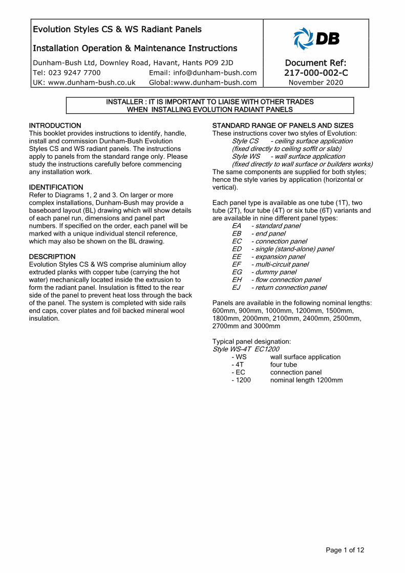
Diagram 6: Typical section details for installation; Styles CS-4T and WS-4T
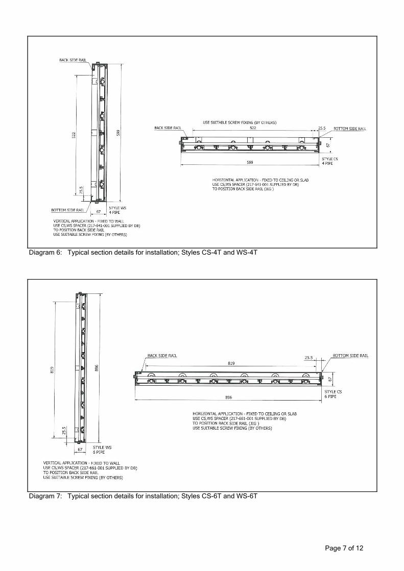
Diagram 7: Typical section details for installation; Styles CS-6T and WS-6T
Page 8 of 12
INSTALLATION
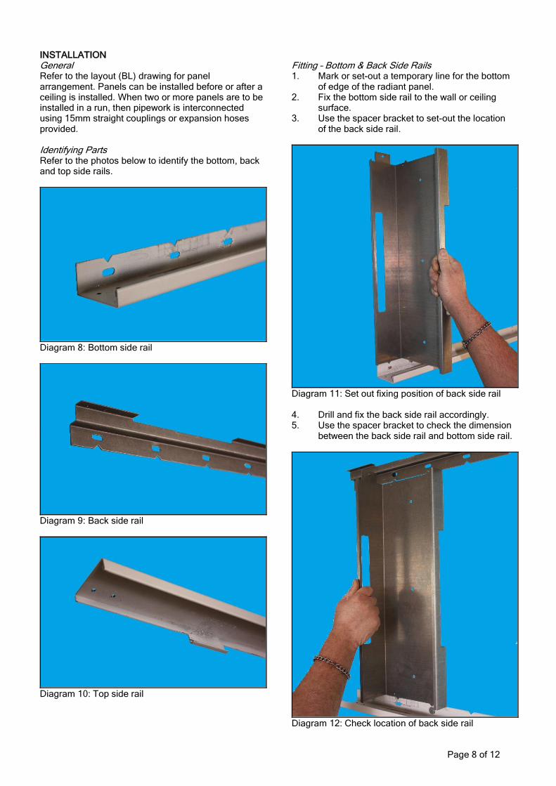
General Refer to the layout (BL) drawing for panel arrangement. Panels can be installed before or after a ceiling is installed. When two or more panels are to be installed in a run, then pipework is interconnected using 15mm straight couplings or expansion hoses provided. Identifying Parts Refer to the photos below to identify the bottom, back and top side rails.
Diagram 8: Bottom side rail
Diagram 9: Back side rail
Diagram 10: Top side rail
Fitting – Bottom & Back Side Rails 1. Mark or set-out a temporary line for the bottom of edge of the radiant panel. 2. Fix the bottom side rail to the wall or ceiling surface. 3. Use the spacer bracket to set-out the location of the back side rail.
Diagram 11: Set out fixing position of back side rail 4. Drill and fix the back side rail accordingly. 5. Use the spacer bracket to check the dimension between the back side rail and bottom side rail.
Diagram 12: Check location of back side rail
Page 9 of 12
Fitting - Radiant Panels & Top Side Rails 1. Clean and flux tube ends where any soldered joints are to be made. 2. Fit insulation to the rear of the radiant panel. 3. Locate the radiant panel into the bottom side rail, lining the end of the radiant panel up with the end of the bottom side rail. 4. Tilt the panel until it is vertical, holding the panel in place.
Diagram 13: Locate panel into bottom side rail 5. Slide the panel along by approximately 50mm to secure the panel in place (see Diagram 14) ensuring all pipe joints are made.
Diagram 14: Slide panel into place.
6. Fit and fix the top side rail to the back side rail (with self drill/self tap screws provided) to retain the radiant panel
Diagram 15: Fit the top side rail 7. Centralise the slip couplings on the pipe joints. apply heat to make each joint to an accepted method (see Diagram 16) 8. Ensure that panels are interconnected correctly. EC, EH and EJ panels are positioned at the connection end (flow and return) of panel run, whereas EB panels are positioned at the opposite end. EA and EE panels are used at intermediate positions – refer to Diagram3. ED panels are single (stand-alone) panels. 9. Refer to Pipework Connections for connecting the panels to the mains. Expansion Joints 1. Expansion panels should be fitted: i) every 6m of straight panel run for 1T (150mm nominal width) 2T (300mm nominal width) 4T (600mm nominal width) ii) every panel joint of straight run for 6T (900mm nominal width). 2. Expansion hoses should be fitted in place of the slip couplings. Note that the hoses will require pre-bending prior to fitting (see Diagram 17). 3. Expansion hoses allow for differential expansion between the copper pipe and the aluminium extrusion in the panels. Fitting - End Caps & Cover Plates 1. Remove protective film from radiating surface. 2. Fit end caps with self drill/tap screws and screw caps provided. 3. Fit cover plates where provided between panels using self drill/tap screws and screwcaps provided.
Page 10 of 12
Pipework connections 1. Connection to the mains is made via EC, ED, EH and EJ panels. EC and ED panels are plain 15mm plain.copper tube. EH and EJ panels are plain 15 or 22mm copper tube, specified at order stage. Flow and return connections are interchangeable.
2. The installer must provide suitable fittings to connect the panels. Flexible hoses are recommended to allow for rapid installation and flexibility. 3. Local isolating and regulating valves are recommended, as well as drains, vents and strainers.
Diagram 16: Installation detail of Evolution Styles CS & WS - standard joint
COMMISSIONING 1. Check the fastness of all fixings. Ensure that the insulation is fitted correctly and that the radiating surface is not damaged. 2. Purge the air from the system using air vents in the mains (by others). 3. Hydraulically pressure test the panels and check for leaks. Refer to Table 2 for test and working pressures.
4. Balance the water flow rate through the panel to accepted practice to achieve the specified flow 5. Leave this document and any layout drawings with the end-user
Maximum cold test pressure 10.5 bar gauge
Maximum working pressure at 90°C 7.0 bar gauge
Table 2 : Recommended test and working pressures GENERAL GUIDANCE 1. Preparation Planning and preparation of building fabric is important; surfaces should be flat, smooth and free from all obstructions prior to panel installation. It is essential to co-ordinate all installation works with other trades. 2. Layout Panel runs should be set out on a layout plan. Radiant panels should be concentrated in areas of highest heat loss i.e. around the outside perimeter of the room, particularly, near windows. This will counteract disproportionately high heat losses. Single or dual circuit runs should be considered- see Water flow rates and Hydraulic Resistances below. 3. Maximum mounting height There is no maximum mounting height for Evolution. However, when mounting heights exceed 4m, the heat load should be adjusted to allow additional losses of radiant heat incident on walls, and stratification of air which absorbs some heat by convection. 4. Minimum mounting height There is no minimum mounting height for Evolution. For comfort and safety, the rule-of- thumb minimum mounting height is 2.4m. Contact Dunham-Bush for further information 5. Wall installation at an angle Style WS panels can be provided with bespoke angle brackets to direct radiant heat towards floor level (see Diagram 12 for an example). 6. Panel runs Refer to Diagram 3 for typical arrangements in a panel run. Dunham-Bush will prepare complete baseboard layout drawings for approval, which can be used to co-ordinate materials and installation on site. 7. Water flow rates To ensure rated heat outputs are achieved, water velocity in the tube should be such the water flow is turbulent. This maximises heat- transfer from the water, through the tube and to the radiating surface. Water flow rates should also be limited to inhibit noise and erosion and high pressure drops. Water flow should ideally be between 0.011 – 0.141kg/s.
8. Hydraulic resistances Evolution utilises 15mm OD copper tube to transport hot water. To calculate the total pressure drop, determine the water flow rate :- Water flow = Q rate (kg/s) Cp x ΔT Q = total heat output from panel run (kW) Cp = specific heat capacity of water (kJ/kgK); approx. 4.187 for most applications ΔT = water temperature drop Obtain the hydraulic resistance from the graph. Note that the water flow rate should be halved if dual circuit panel runs are used (i.e. type EFpanels). N.B. circuit length applies for one circuit only Similarly, the water flow rate should be divided by four or six for panels with parallel circuits (i.e. type EH and EJ panels – see page 4.)
Diagram 19: Special bespoke angle brackets for Style WS installation (contact Dunham-Bush for details) MAINTENANCE Dunham-Bush Evolution radiant panels are essentially maintenance free, with no moving parts. Panel surfaces can be washed with mild cleaner or detergent followed by rinsing. Strong, abrasive or mechanical cleaning should not be used. If panels or accessories become damaged, they can be replaced after isolating, draining and disconnecting from pipework or adjacent panels. SPARES/SERVICE
PLEASE WRITE THE DETAILS OF RADIANT PANELS HERE. These details will be required when ordering spares for your Dunham-Bush radiant panels STYLE AND No. OF TUBES BL DRAWING OR ORDER No. DATE OF INSTALLATION
Spare parts/service – Please contact our office, contact information shown below. Manufacturer reserves the right to change any product specification without notice.