EXAMPLES OF BRIDGE DAMAGE ON METROPOLITAN EXPRESSWAY DISCOVERED BY EMERGENCY STRUCTURAL INSPECTIONS AFTER THE TOHOKU EARTHQUAKE Tsuyoshi KOSUGI 1 Takehiko HATSUKU 2 Masaru SHIMONISHI 3 Abstract The Tohoku Earthquake on March 11, 2011 (Heisei 23) was observed to be seismic intensity 5 Upper by the JMA intensity scale even in the Tokyo Metropolitan area, which is more than 300 km from the epicenter. Even the Metropolitan Expressway took heavy damage centered on the coastal regions where the shaking was strong. In this article, we introduce the results of the emergency inspections of the Metropolitan Expressway conducted after the earthquake and examples of the damage discovered. From the bridge pier inspections targeting bearings and earthquake-resistance reinforcements, it is clearly necessary to focus on damage around bearings when elevated bridges have major curvature or inclination such as in junctions, as well as when piers are steel structures. In addition, considerable surface difference in level was observed in areas where the piers were constructed on reclaimed land, and the reason is thought cavities that occurred by land subsidence before the earthquake become larger as a result of the earthquake. 1. Introduction The world's largest magnitude 9.0 earthquake, with an epicenter off the Sanriku coast in the Pacific Ocean, struck Japan on March 11, 2011. Not only was there damage from the tremors of this earthquake's seismic motion, but Japan witnessed the greatest disaster in her history due to the effects from the giant tsunami that hit the Pacific coast of the Tohoku region. This earthquake was observed to be seismic intensity 5 Upper even in the Tokyo Metropolitan area, which is more than 300 km from the epicenter (Figure 1-1). Thus, the Metropolitan Expressway took damages centered on the elevated bridges in the coastal 1 Group Leader of Third Management Division, Structural Management Department, Shutoko Engineering Co., Ltd. 2 Manager of Engineering and Consulting Division, Planning Department, Shutoko Engineering Co., Ltd. 3 Deputy Manager of Maintenance Management Division, Kanagawa Operation Bureau, Metropolitan Expressway Co., Ltd.
Transcript
EXAMPLES OF BRIDGE DAMAGE ON METROPOLITAN EXPRESSWAY DISCOVERED BY EMERGENCY STRUCTURAL INSPECTIONS AFTER THE
TOHOKU EARTHQUAKE
Tsuyoshi KOSUGI1
Takehiko HATSUKU2
Masaru SHIMONISHI3
Abstract
The Tohoku Earthquake on March 11, 2011 (Heisei 23) was observed to be seismic intensity 5 Upper by the JMA intensity scale even in the Tokyo Metropolitan area, which is more than 300 km from the epicenter. Even the Metropolitan Expressway took heavy damage centered on the coastal regions where the shaking was strong. In this article, we introduce the results of the emergency inspections of the Metropolitan Expressway conducted after the earthquake and examples of the damage discovered.
From the bridge pier inspections targeting bearings and earthquake-resistance reinforcements, it is clearly necessary to focus on damage around bearings when elevated bridges have major curvature or inclination such as in junctions, as well as when piers are steel structures. In addition, considerable surface difference in level was observed in areas where the piers were constructed on reclaimed land, and the reason is thought cavities that occurred by land subsidence before the earthquake become larger as a result of the earthquake.
1. Introduction
The world's largest magnitude 9.0 earthquake, with an epicenter off the Sanriku coast in the Pacific Ocean, struck Japan on March 11, 2011. Not only was there damage from the tremors of this earthquake's seismic motion, but Japan witnessed the greatest disaster in her history due to the effects from the giant tsunami that hit the Pacific coast of the Tohoku region.
This earthquake was observed to be seismic intensity 5 Upper even in the Tokyo Metropolitan area, which is more than 300 km from the epicenter (Figure 1-1). Thus, the Metropolitan Expressway took damages centered on the elevated bridges in the coastal
1 Group Leader of Third Management Division, Structural Management Department, Shutoko Engineering Co., Ltd.2 Manager of Engineering and Consulting Division, Planning Department, Shutoko Engineering Co., Ltd. 3 Deputy Manager of Maintenance Management Division, Kanagawa Operation Bureau, Metropolitan Expressway Co., Ltd.
areas where the tremors were strong. With around a year and a half having passed since then, there has been much social
loss in this earthquake, but for those of us in the position to protect the Metropolitan Expressway, the reality is that we have simultaneously learned many lessons. In order to help the operation and maintenance of the expressway without forgetting this valuable experience, this article will introduce examples of damage discovered by emergency inspections conducted after the earthquake.
Figure 1-1 Epicenter and Distribution of Seismic Intensity [1]
2. Overview of the Metropolitan Expressway
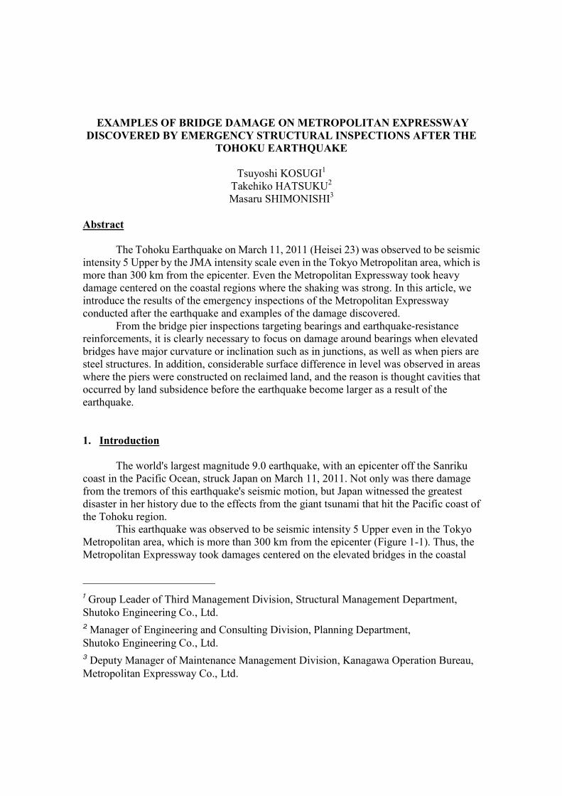
The Metropolitan Expressway was built in 1962 between Kyobashi and Shibaura (4.5 km) to ease the automotive congestion in the capital and to facilitate smooth transportation. Today, the Metropolitan Expressway network exceeds 300 km, and plays an important role as a primary traffic route that sustains the industry and livelihood of the Tokyo area (Figure 2-1).
Elevated structures account for around 80% of the Metropolitan Expressway due to site restraints that result from being built within the urban area, and combined with the tunnels and semi-underground structures, they account for 95% of so-called “the ratio of structure” [2]. The structural classification of the Metropolitan Expressway is shown in Table 2-1 and Figure 2-2.
Seismic intensity
7
6+
6ー
5+
5ー
4
3
2
1
38° 6′ 2″N142°51′ 6″E
Sapporo
Sendai
Nagoya Osaka
Kochi
Fukuoka
The Pacific OceanThe Sea Of Japan
N
(Shindo)
Tokyo
Yokohama
Tokyo Metropolitan area
3. Role of Shutoko Engineering Co., Ltd.
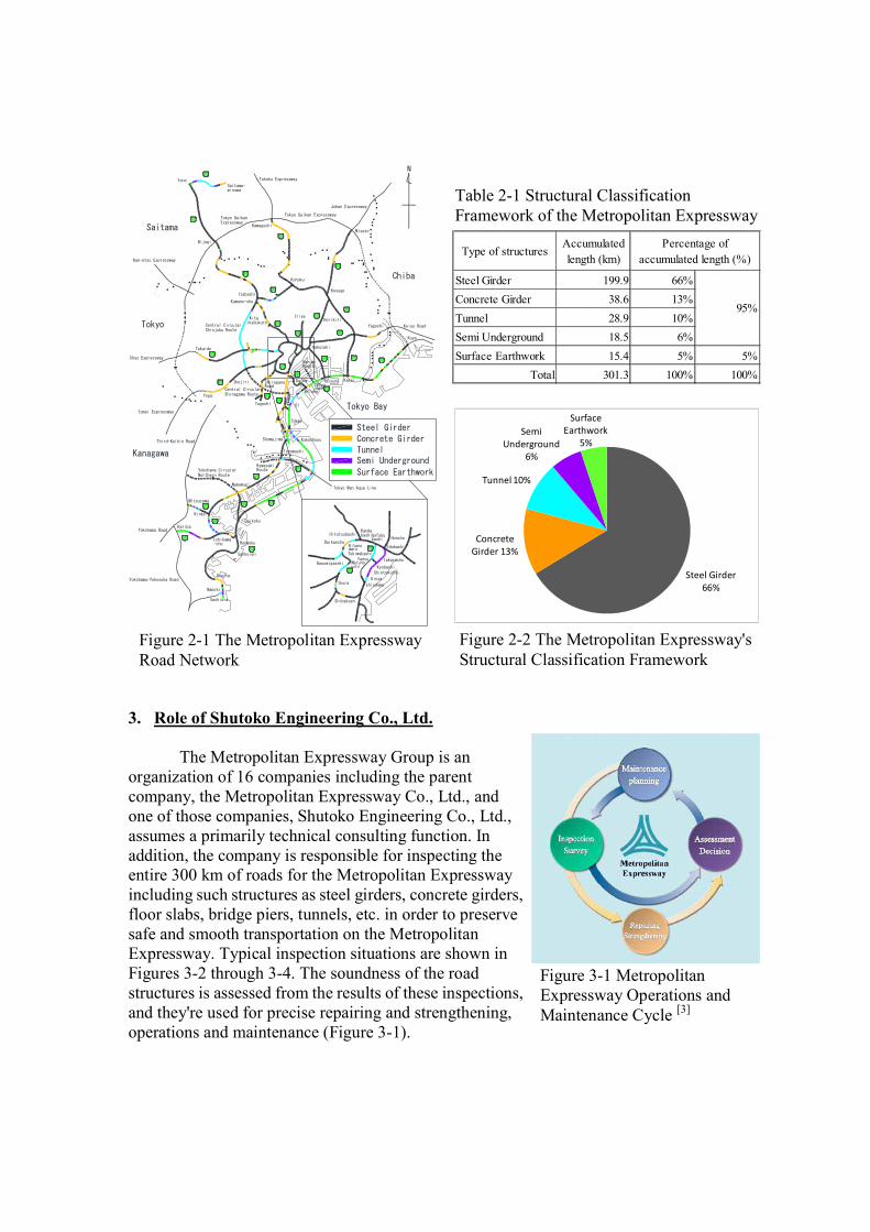
The Metropolitan Expressway Group is an organization of 16 companies including the parent company, the Metropolitan Expressway Co., Ltd., and one of those companies, Shutoko Engineering Co., Ltd., assumes a primarily technical consulting function. In addition, the company is responsible for inspecting the entire 300 km of roads for the Metropolitan Expressway including such structures as steel girders, concrete girders, floor slabs, bridge piers, tunnels, etc. in order to preserve safe and smooth transportation on the Metropolitan Expressway. Typical inspection situations are shown in Figures 3-2 through 3-4. The soundness of the road structures is assessed from the results of these inspections, and they're used for precise repairing and strengthening, operations and maintenance (Figure 3-1).
Figure 2-2 The Metropolitan Expressway's Structural Classification Framework
Steel Girder 66%
Concrete Girder 13%
Tunnel 10%
Semi Underground
6%
Surface Earthwork
5%
Figure 3-1 Metropolitan Expressway Operations and Maintenance Cycle [3]
Table 2-1 Structural Classification Framework of the Metropolitan Expressway
Figure 2-1 The Metropolitan Expressway Road Network
Figure 3-2 (upper left) Daily Patrol Car Inspections Figure 3-3 (lower left) Daily Inspections from under Elevated Structures Figure 3-4 (right) Periodical Inspections Using Aerial Vehicles
4. State of the Damage of the Metropolitan Expressway
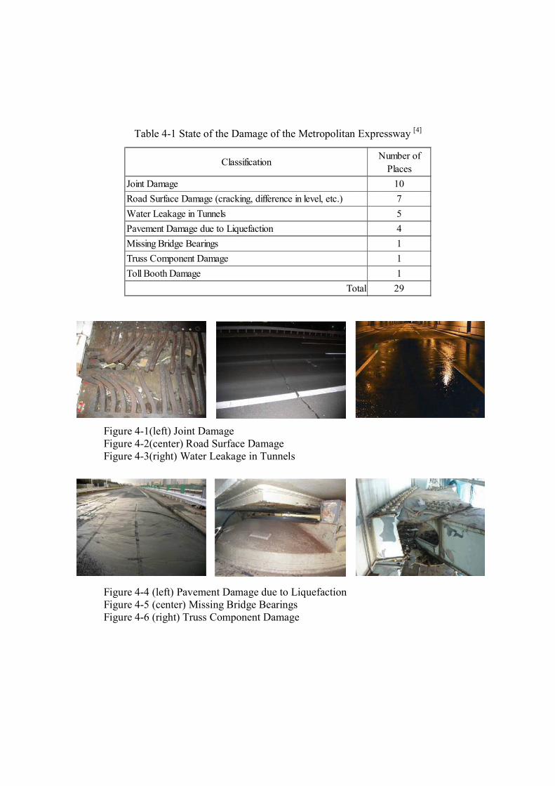
All roads of the Metropolitan Expressway were closed and emergency patrols and inspections were conducted immediately after the earthquake because a maximum seismic intensity of 5 Upper was felt within the jurisdiction of the Metropolitan Expressway. The main damage found in the inspections immediately after the earthquake is shown in Table 4-1 and Figures 4-1 through 4-6. Fortunately, the Tokyo area was not affected by a tsunami, but the damage on the Metropolitan Expressway was most serious in its history.
In response to this damage, emergency measures were implemented rapidly, and once they were verified to be safe, road closures were cancelled in all but one area by 3 days after the earthquake on March 14. In addition, even in the places that they could not be opened for traffic immediately, active restoration work continued after that, and all road closures were lifted 16 days after the earthquake on March 27.
Table 4-1 State of the Damage of the Metropolitan Expressway [4]
Figure 4-1(left) Joint Damage Figure 4-2(center) Road Surface Damage Figure 4-3(right) Water Leakage in Tunnels
Figure 4-4 (left) Pavement Damage due to Liquefaction Figure 4-5 (center) Missing Bridge Bearings Figure 4-6 (right) Truss Component Damage
Classification Number ofPlaces
Joint Damage 10Road Surface Damage (cracking, difference in level, etc.) 7Water Leakage in Tunnels 5Pavement Damage due to Liquefaction 4Missing Bridge Bearings 1Truss Component Damage 1Toll Booth Damage 1
Total 29
5. Special Bridge Pier Inspections in the Kanagawa Area
5.1 Inspection Overview
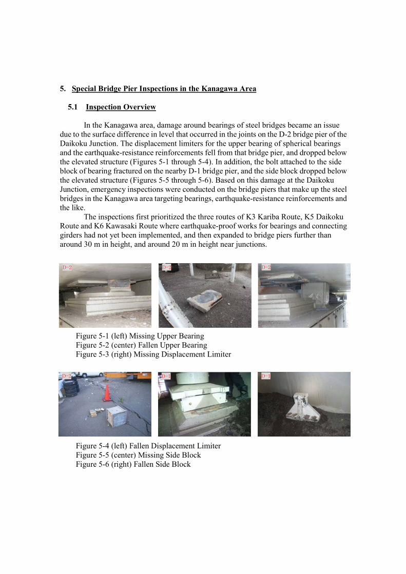
In the Kanagawa area, damage around bearings of steel bridges became an issue due to the surface difference in level that occurred in the joints on the D-2 bridge pier of the Daikoku Junction. The displacement limiters for the upper bearing of spherical bearings and the earthquake-resistance reinforcements fell from that bridge pier, and dropped below the elevated structure (Figures 5-1 through 5-4). In addition, the bolt attached to the side block of bearing fractured on the nearby D-1 bridge pier, and the side block dropped below the elevated structure (Figures 5-5 through 5-6). Based on this damage at the Daikoku Junction, emergency inspections were conducted on the bridge piers that make up the steel bridges in the Kanagawa area targeting bearings, earthquake-resistance reinforcements and the like.
The inspections first prioritized the three routes of K3 Kariba Route, K5 Daikoku Route and K6 Kawasaki Route where earthquake-proof works for bearings and connecting girders had not yet been implemented, and then expanded to bridge piers further than around 30 m in height, and around 20 m in height near junctions.
Figure 5-4 (left) Fallen Displacement Limiter Figure 5-5 (center) Missing Side Block Figure 5-6 (right) Fallen Side Block
D-2 D-2
D-1 D-1
D-2
D-2
5.2 Inspection Results
Places thought to have the greatest influence from the earthquake were selected, and the results of the inspections of approx. 350 bridge piers confirmed damage on 6 new bridge piers. Together with the D-2 and D-1 piers, these inspections brought the total to 8 bridge piers. The inspection results are shown in Figure 5-7 and Table 5-1, and the main damage is shown in Figures 5-8 through 5-10.
Fractures of bolts attached to side block in the rubber bearings, and cracks of upper bearings and fractures of setting bolts in the spherical bearings were discovered. In the 6 new bridge piers where damage was confirmed, luckily the components did not drop below the elevated structure, but it can be said the effect of the earthquake to bridges was remarkable.
The results of these emergency inspections show that damage around bearings is concentrated near junctions. Since the curvature and incline of the superstructure is comparatively large in the vicinity of the junctions, it can be presumed they exhibit unforeseen behavior due to the earthquake. In addition, the bridge piers where damage was found were all steel structures. High-rise bridge piers are generally steel structures, and the difference in rigidity is thought to be one of the primary factors in steel bridge piers more easily swaying than reinforced concrete bridge piers.
The logical conclusion from these tendencies indicates that superstructures may exhibit unforeseen behavior when elevated bridges have large curvature and incline like at junctions, as well as when bridge piers are steel structures. In these places, it is necessary to pay attention to damage around bearings after earthquakes.
Figure 5-7 Bridge Pier Inspection Range and Damaged Locations Sachiura
Sugita
Isogo
sankeien
Ukishima
Wangan-Ringroad-No.8
Tonomachi
Kuko Chuo
Shinyamashita
Yamashita-cho
Ishikawa-cho
Bandobashi
Hananoki
Nagata
Yokohamakouen
Minatomirai
Yokohama Station
East entrance
Mitsuzawa
Higashikanagawa Koyasu
Moriyacho
NamamugiAsada
Shioiri
Hamakawasaki
Kuko nishi
Haneda
Taishi
Taishi
Honmoku-wharf
Higashi-ogijima
Oiminami
Heiwajima
Suzugamori
Katsushima
Heiwajima
KaribaIC
Ishikawa-choJCT
HonmokuJCT
DaikokuJCT
NamamugiJCT
Kawasaki-ukishimaJCT
TaishiJCT
TokaiJCT
ShowajimaJCT
Yokoham
a Bay
Bridge
Tsurumi Tsubasa Bridge
Route 5
(Daikoku Line)
Bay Shore Route
Bay Shore Route( 5-period )
Route 3
(Kariba Line
)
Route 1
(Yokohane Line)
Route
6
(Kawa
saki Line
)
Taishi-Tunnel
Kawasaki-Service Tunnel
Tamagawa-Tunnel
Yokohama-Yokosuka Road
Yokohama Road
Hodogaya bypass
Third-Keihin Road
First-
keihin
Road
Second
-keihi
n Road
Ringroad
No .8
Ringr
oad No.7
Tokyo Wan Aqua Line
Property
Boundary
Property
Boundary
HodogayaIC
Yokohama CityKawasaki City
Kanagawa
Tokyo
Minamikaruizawa-Tunnel
Hanazonobashi-Tunnel
Hanazono-Tunnel
Sakuragicho-Tunnel
Higashiyokohama-Tunnel
Mitsuzawa-Tunnel
Namiki-Tunnel
N
Inspection Range
Yokohama Station
West entrance
Higashi-ogijima
Daikoku-wharf
KinkoJCT
Route 2
(Mitsuzawa Line
)
K-4K-1,2,3
D-4
D-2
D-1
D-3
Table 5-1 Bridge Piers where Damage was Confirmed in the Bearings and their Main Damage
Figure 5-8 (left) Fractured Bolts Figure 5-9 (center) Crack of Upper Bearing Figure 5-10 (right) Deformation of Upper Bearing
6. Ground Subsidence Investigation around the Bridge Piers at Daikoku Junction
6.1 Investigation Overview
Below the elevated structure of Daikoku Junction where there was damage around bearings of the steel bridge, the peripheral ground sunk leaving the bridge pier foundations, and striking surface difference in level occurred after the earthquake. Depending on the location, fissures in the ground occurred around the foundation, and there were also places where the pavement collapsed. Since the Daikoku Wharf, where the Daikoku Junction is built, is on reclaimed land, the land has been sinking since before the earthquake, and it is thought the damage has expanded even further as a result of the earthquake.
There is not a public road below the elevated structure of the Daikoku Junction, but there is a logistics center representing the Yokohama Port and Harbor Authority's fleet vehicles, and there is also a Metropolitan Expressway parking area. Since there is a possibility the deformation from the ground subsidence is affecting the use of these
K-1 K-4 D-4
Route Pier No. SiteRigid orSeparate Type of Substructure Height Main Damage
26.54 BP-A Spherical Bearing Deformation of upper bearing
Type of Bearing
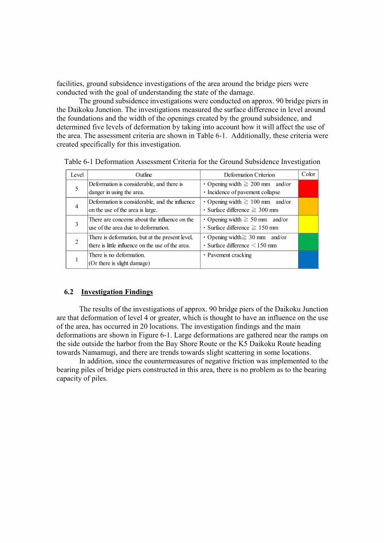
facilities, ground subsidence investigations of the area around the bridge piers were conducted with the goal of understanding the state of the damage.
The ground subsidence investigations were conducted on approx. 90 bridge piers in the Daikoku Junction. The investigations measured the surface difference in level around the foundations and the width of the openings created by the ground subsidence, and determined five levels of deformation by taking into account how it will affect the use of the area. The assessment criteria are shown in Table 6-1. Additionally, these criteria were created specifically for this investigation.
Table 6-1 Deformation Assessment Criteria for the Ground Subsidence Investigation
6.2 Investigation Findings
The results of the investigations of approx. 90 bridge piers of the Daikoku Junction are that deformation of level 4 or greater, which is thought to have an influence on the use of the area, has occurred in 20 locations. The investigation findings and the main deformations are shown in Figure 6-1. Large deformations are gathered near the ramps on the side outside the harbor from the Bay Shore Route or the K5 Daikoku Route heading towards Namamugi, and there are trends towards slight scattering in some locations.
In addition, since the countermeasures of negative friction was implemented to the bearing piles of bridge piers constructed in this area, there is no problem as to the bearing capacity of piles.
Level Outline Deformation Criterion Color
5Deformation is considerable, and there isdanger in using the area.
・Opening width ≧ 200 mm and/or・Incidence of pavement collapse
4Deformation is considerable, and the influenceon the use of the area is large.
・Opening width ≧ 100 mm and/or・Surface difference ≧ 300 mm
3There are concerns about the influence on theuse of the area due to deformation.
・Opening width ≧ 50 mm and/or・Surface difference ≧ 150 mm
2There is deformation, but at the present level,there is little influence on the use of the area.
・Opening width≧ 30 mm and/or・Surface difference <150 mm
1There is no deformation.(Or there is slight damage)
Figure 6-1 Ground Subsidence Investigation Findings and Main Deformation
Direction of Namamugi
Direct
ion of
Ukish
ima
Direction of Honmoku
Route 5(Daikoku Line)
Bay Shore Route
DaikokuPA
Level 3
Level 1
Level 4
Level 5
Level 2
D-5
D-4
D-6
D-3
D-1D-2
Daikoku JCT
6.3 Additional Investigation
The deformation around bridge pier D-6 is considerable with a large cavity occurring around the foundation of the bridge pier, and the pavement has collapsed. It is possible there was a cavity under the footing from before the earthquake, and earth and sand is filling in the area around there. Accordingly, an observation well was set up by boring in a position 2.5 m from the bridge pier, and after surveying the underground situation with a video scope (Figure 6-2), partial cavities were confirmed at a depth of 6.5 m directly below the footing and again under that at a depth of 7.3 m. The findings and an image of the cavity occurrences are shown in Figure 6-3. In line with the conjecture, there is a possibility earth and sand around the bridge pier was filling in the area under the footing from before the earthquake and there already was a cavity under the pavement surface. In these investigations, detailed situation around the foundation was not manifested, but it is thought these deformations such as surface difference and the like are the results of the effect that the earthquake extended latent conditions.
Among the 4 bridge piers at the Daikoku Junction that took damages around bearings, major surface difference in level occurred around the foundation for the D-2 and D-4 bridge piers. The relationship between these is not definite, but if hypothetically there were cavities under the footing or at the side of the footing, then it can be thought the tremor amplitude of such bridge piers becomes bigger due to degradation in the ground resistance that the footing received, as compared with sound bridge piers of same height. The influence of ground subsidence on the behavior of elevated bridges is not clear, but it may be necessary to study this relationship to prepare for future earthquakes.
Figure 6-2 Video Scope
Groundwater Level (GL-5500)
Pier Stud
Cavity
Footing
Steel Pipe Pile
2500
3400
Cavity
Cavity(GL-6500)Cavity(GL-7300)
Figure 6-3 Results of Additional Investigation and Image of Cavity Occurrence
Flow of Earth and Sand
7. Summary
The following knowledge was gained from the inspections after this earthquake.
It is necessary to pay attention to damage around bearings of elevated bridges, because there is a possibility superstructures will move unexpectedly when they have structures with large curvature or inclines like at junctions, and when their bridge piers are steel structures.
At the bridge piers constructed on such soft ground as reclaimed land, it is necessary to pay attention to subsidence and surface difference around the foundation, because there is a possibility cavities occurred due to the consolidation settlement, then earth and sand is filling in those cavities.
8. Conclusion
Various deformations were discovered by the investigations after the earthquake. It is necessary to continue to inspect the structures while bearing in mind the effects of the earthquake for a time. In addition, it is hoped this valuable experience will be made use of the operations and maintenance on the Metropolitan Expressway from now on.
Acknowledgments
We especially thank members related to the maintenance management in the Metropolitan Expressway Co., Ltd. for their appropriate advices and guides as well as their support throughout entire process to complete this paper.
References
[1] Earthquake and Tsunami Information (The 2011 off the Pacific Coast of Tohoku Earthquake), Japan Meteorological Agency, 17 August 2011
[2] Fukashi Kogure, Structural management of 300 km-long Metropolitan Expressway, Bridge and Foundation Engineering, Vol.44, 2010
[3] Brochure/Engineering and Consulting Service of Metropolitan Expressway Group, Metropolitan Expressway Co., Ltd. etc.