Excel 3000 Series Powder Coating System Customer Product Manual Part 1095480A Issued 2/10 NORDSON CORPORATION • AMHERST, OHIO • USA For parts and technical support, call the Finishing Customer Support Center at (800) 433-9319. This document is available on the Internet at http://emanuals.nordson.com/finishing
Transcript
Excel 3000 SeriesPowder Coating System
Customer Product ManualPart 1095480A
Issued 2/10
NORDSON CORPORATION • AMHERST, OHIO • USA
For parts and technical support, call the Finishing Customer Support Center at (800) 433-9319.
This document is available on the Internet at http://emanuals.nordson.com/finishing
Part 1095480A � 2010 Nordson Corporation
Contact UsNordson Corporation welcomes requests for information, comments, andinquiries about its products. General information about Nordson can befound on the Internet using the following address:http://www.nordson.com.Address all correspondence to:
Nordson CorporationAttn: Customer Service555 Jackson StreetAmherst, OH 44001
NoticeThis is a Nordson Corporation publication which is protected by copyright.Original copyright date 2009. No part of this document may bephotocopied, reproduced, or translated to another language without theprior written consent of Nordson Corporation. The information containedin this publication is subject to change without notice.
Trademarks
The Nordson logo, PowderGrid, Smart-Coat, Sure Coat, Tribomatic, andVersa-Spray are registered trademarks of Nordson Corporation.
IntroductionRead and follow these safety instructions. Task- and equipment-specificwarnings, cautions, and instructions are included in equipmentdocumentation where appropriate.
Make sure all equipment documentation, including these instructions, isaccessible to all persons operating or servicing equipment.
Qualified PersonnelEquipment owners are responsible for making sure that Nordson equipmentis installed, operated, and serviced by qualified personnel. Qualifiedpersonnel are those employees or contractors who are trained to safelyperform their assigned tasks. They are familiar with all relevant safety rulesand regulations and are physically capable of performing their assignedtasks.
Intended UseUse of Nordson equipment in ways other than those described in thedocumentation supplied with the equipment may result in injury to personsor damage to property.
Some examples of unintended use of equipment include
� using incompatible materials
� making unauthorized modifications
� removing or bypassing safety guards or interlocks
� using incompatible or damaged parts
� using unapproved auxiliary equipment
� operating equipment in excess of maximum ratings
Safety1-2
Part 1095480A � 2010 Nordson Corporation
Regulations and ApprovalsMake sure all equipment is rated and approved for the environment in whichit is used. Any approvals obtained for Nordson equipment will be voided ifinstructions for installation, operation, and service are not followed.
All phases of equipment installation must comply with all federal, state, andlocal codes.
Personal SafetyTo prevent injury follow these instructions.
� Do not operate or service equipment unless you are qualified.
� Do not operate equipment unless safety guards, doors, or covers areintact and automatic interlocks are operating properly. Do not bypass ordisarm any safety devices.
� Keep clear of moving equipment. Before adjusting or servicing anymoving equipment, shut off the power supply and wait until theequipment comes to a complete stop. Lock out power and secure theequipment to prevent unexpected movement.
� Relieve (bleed off) hydraulic and pneumatic pressure before adjusting orservicing pressurized systems or components. Disconnect, lock out,and tag switches before servicing electrical equipment.
� Obtain and read Material Safety Data Sheets (MSDS) for all materialsused. Follow the manufacturer’s instructions for safe handling and useof materials, and use recommended personal protection devices.
� To prevent injury, be aware of less-obvious dangers in the workplacethat often cannot be completely eliminated, such as hot surfaces, sharpedges, energized electrical circuits, and moving parts that cannot beenclosed or otherwise guarded for practical reasons.
Fire SafetyTo avoid a fire or explosion, follow these instructions.
� Do not smoke, weld, grind, or use open flames where flammablematerials are being used or stored.
� Provide adequate ventilation to prevent dangerous concentrations ofvolatile materials or vapors. Refer to local codes or your material MSDSfor guidance.
� Do not disconnect live electrical circuits while working with flammablematerials. Shut off power at a disconnect switch first to preventsparking.
Safety 1-3
Part 1095480A� 2010 Nordson Corporation
� Know where emergency stop buttons, shutoff valves, and fireextinguishers are located. If a fire starts in a spray booth, immediatelyshut off the spray system and exhaust fans.
� Clean, maintain, test, and repair equipment according to the instructionsin your equipment documentation.
� Use only replacement parts that are designed for use with originalequipment. Contact your Nordson representative for parts informationand advice.
Grounding
WARNING: Operating faulty electrostatic equipment is hazardous and cancause electrocution, fire, or explosion. Make resistance checks part of yourperiodic maintenance program. If you receive even a slight electrical shockor notice static sparking or arcing, shut down all electrical or electrostaticequipment immediately. Do not restart the equipment until the problem hasbeen identified and corrected.
All work conducted inside the spray booth or within 1 m (3 ft) of boothopenings is considered within a Class 2, Division 1 or 2 Hazardous locationand must comply with NFPA 33, NFPA 70 (NEC articles 500, 502, and 516),and NFPA 77, latest conditions.
� All electrically conductive objects in the spray areas shall be electricallyconnected to ground with a resistance of not more than 1 megohm asmeasured with an instrument that applies at least 500 volts to the circuitbeing evaluated.
� Equipment to be grounded includes, but is not limited to, the floor of thespray area, operator platforms, hoppers, photoeye supports, andblow-off nozzles. Personnel working in the spray area must begrounded.
� There is a possible ignition potential from the charged human body.Personnel standing on a painted surface, such as an operator platform,or wearing non-conductive shoes, are not grounded. Personnel mustwear shoes with conductive soles or use a ground strap to maintain aconnection to ground when working with or around electrostaticequipment.
� Operators must maintain skin-to-handle contact between their hand andthe gun handle to prevent shocks while operating manual electrostaticspray guns. If gloves must be worn, cut away the palm or fingers, wearelectrically conductive gloves, or wear a grounding strap connected tothe gun handle or other true earth ground.
� Shut off electrostatic power supplies and ground gun electrodes beforemaking adjustments or cleaning powder spray guns.
� Connect all disconnected equipment, ground cables, and wires afterservicing equipment.
Safety1-4
Part 1095480A � 2010 Nordson Corporation
Action in the Event of a MalfunctionIf a system or any equipment in a system malfunctions, shut off the systemimmediately and perform the following steps:
� Disconnect and lock out electrical power. Close pneumatic shutoffvalves and relieve pressures.
� Identify the reason for the malfunction and correct it before restarting theequipment.
DisposalDispose of equipment and materials used in operation and servicingaccording to local codes.
Description 2-1
Part 1095480A� 2010 Nordson Corporation
Section 2Description
IntroductionThis manual covers Excel 3000 powder coating systems. It includes systemoperation, maintenance, and troubleshooting procedures. Spray boothrepair procedures and parts lists are also included. Review this manual andthe manuals for the other components of your system before operating yourNordson powder coating system.
System ConfigurationA complete powder coating system consists of powder applicationequipment and powder recovery/reclaim equipment. Systems are designedand configured for each customer’s application. This manual describes abasic, manually operated system. Your system may have equipment notdescribed in this manual, such as automatic gun triggering and airmanagement systems. Before operating your system, please read themanuals for all equipment not covered in this manual.
The system can be permanently located under the conveyor, or mounted oncasters and rails (roll-on/roll-off system) to allow it to be moved off-line forpowder changes or maintenance.
Figure 2-2 illustrates the operation of the typical system. Figures 2-3, 2-4,and 2-5 shows the locations of the components in a typical system.
Figure 2-1 Excel 3000 Powder Coating System (Shown with Optional Equipment)
Description2-2
Part 1095480A � 2010 Nordson Corporation
System OperationSee Figure 2-2.
Powder ApplicationA porous fluidizing plate in the bottom of the feed hopper (11) diffuseslow-pressure compressed air into the powder supply. The air fluidizes thepowder so it can be pumped to the spray guns. The fluidizing air flows intothe color module (17) through a vent duct. In the color module, thecartridge filters separate powder dust from the fluidizing air.
The powder pumps (12) draw the powder out of the hopper, mix it with ahigh-velocity stream of air, and force it through feed hoses (15) to thepowder spray guns (1). The spray guns electrostatically charge the powderand spray it onto the workpieces (3) passing through the booth. Thecharged powder sticks to the grounded workpieces.
Powder Recovery and ReclaimAn exhaust fan (5) pulls spray-room air into the enclosure (2), through thecartridge filters (4) and color module, and into the fan section (6). The airreturns to the spray room through the final filters (7), free of all powder.
Most of the oversprayed powder remains suspended in the air flowingthrough the enclosure to the cartridge filters. The powder collects on theexternal surfaces of the cartridge filters. At timed intervals, the pulsevalves (8) release large volumes of air through the centers of the cartridgefilters. The air pulse blows the powder off the filters. The powder falls intothe color module hoppers, where it is fluidized.
The transfer pumps (16) pump the reclaimed powder through the transferhoses (14) to the accumulator (9) on top of the sieve (10). The sievescreens the reclaimed powder and discharges particles and clumps toolarge to pass through the sieve screen into a scrap bucket (13). The rest ofthe reclaimed powder falls into the feed hopper. A vent tube connects theaccumulator to the color module. Venting prevents the transfer pump airfrom blowing the powder through the sieve screen and into the scrapbucket.
12. Powder pumps13. Scrap bucket14. Transfer hoses15. Feed hoses16. Transfer pumps17. Color module
Description2-4
Part 1095480A � 2010 Nordson Corporation
System EquipmentThe following paragraphs describe the equipment used in a typical system.
Recovery and Reclaim EquipmentRefer to Table 2-1 and Figure 2-3.
Table 2-1 Recovery and Reclaim Equipment
Item Equipment Description
1 Booth enclosure (canopy) Contains the sprayed powder within the booth. It has aconveyor slot in the roof; exit and entry vestibules; slots forautomatic spray guns; and openings and doors in the sidesfor manual spray gun operators. The color module isattached to a large opening in one side.
2 Fan section Houses the exhaust fan and motor; cartridge filter pulsevalves and manifold; and final filters. A pneumatic sealprovides an air-tight seal between the fan section and thecolor module.
3 Color module Houses cartridge filters; fluidizing plates and plenums; andtransfer pumps. Oversprayed powder accumulates inhoppers in the bottom of the module.
Cartridge Filter Requirements
3001: 12−36 in. center mount cartridges3002: 10−26 in. center mount cartridges,
10−26 in. flo-thru cartridges3003: 12−26 in. center mount cartridges
12−26 in. flo-thru cartridges
4 Accumulator and sieve Collect and screen the powder returned to the feed hopperfrom the color module. Powder particles and clumps toolarge to pass through the sieve screen are discarded. Avent tube and hose connect the accumulator to the colormodule.
5 Transfer pumps Convey the reclaimed powder from the color modulehoppers to the accumulator. A switch on the electricalpanel controls pump operation.
6 Booth base Supports the enclosure and provides mounting points forthe powder inlet frame, fan section support legs, operatorplatform, and other equipment. The base houses most ofthe system’s electrical wiring and pneumatic plumbing.
NS: Not Shown
Description 2-5
Part 1095480A� 2010 Nordson Corporation
1
2
3
4
56
Figure 2-3 Recovery and Reclaim Equipment
1. Booth enclosure2. Fan section
3. Color module4. Accumulator and sieve
5. Transfer pumps6. Booth base
Description2-6
Part 1095480A � 2010 Nordson Corporation
System ControlsRefer to Table 2-2 and Figure 2-4.
Table 2-2 System Controls
Item Equipment Description
1 Flame detectorindicator/relay panel
Provides visible and audible fault and fire alarms andprocess shutdown relays. If a detector senses a flame, theinterlock relays shut down the conveyor, booth exhaust fan,compressed air, and electrical power to the spray guns.ANSI/NFPA-33 standards require flame detectors in allsystems equipped with automatic spray guns.
2 Electrical Panel Houses motor starters and overload protectors;transformers; interlock relays; the final filterdifferential-pressure switches; and basic system controlsand indicator lights. A programmable controller can beinstalled in the panel.
3 Pneumatic panel Houses air-pressure regulators and gauges for the feedhopper, color module, transfer pumps, and other pneumaticequipment.
4 Cartridge filter gauge Monitors the air pressure drop across the cartridge filters.
5 Final filter gauge Monitors the air pressure drop across the final filters. Awarning light on the electrical control panel will light whenthe filters start to clog. The system will shut down when theclogging reaches a critical level.
6 Pulse air controls Regulate the pulse air pressure and volume. Controlsinclude a regulator, pressure gauge, and gate valve.
7 Pneumatic seal control valve Inflates and deflates the seal between the color module andthe fan section. The seal prevents powder from escapinginto the spray room.
8 Flame detectors Monitor the enclosure (booth) interior for flames. Thedetectors use IR sensing technology and providethrough-the-lens self test to check for powder build-up.
9 Pulse-valve timer panel Houses the pulse-valve timer circuit board. Trimpotentiometers on the board adjust pulse delay andduration. LEDs on the board light as each valve istriggered.
Description 2-7
Part 1095480A� 2010 Nordson Corporation
1
2
3
67
45
8
9
Figure 2-4 Typical System Controls
1. Flame detector indicator/relaypanel
2. Electrical panel3. Pneumatic panel
4. Cartridge filter gauge5. Final filters gauge6. Pulse air controls
7. Pneumatic seal control valve8. Flame detectors9. Pulse valve timer panel
Description2-8
Part 1095480A � 2010 Nordson Corporation
Application EquipmentRefer to Table 2-3 and Figure 2-5.
Table 2-3 Application Equipment
Item Equipment Description
1 Automatic spray guns Electrostatically charge powder particles and spray themtoward the grounded workpieces.
2 Automatic gun control units Control air pressure to the powder pumps and generate orcontrol the electrostatic voltage. One gun control unit isrequired for each spray gun. Cabinets house gun controlunits, a master control unit, and air supply controls.
3 Powder pumps Supply spray guns with powder from the feed hopper. Onepump is used for each spray gun.
4 Feed hoppers Store and fluidize the powder supply for automatic andmanual spray guns.
5 Feed-hopper level sensor Monitors the level of powder in the feed hopper. Whentransfer pump controls are set to AUTO, the level sensorwill turn on the transfer pumps when the level of powderfalls below the sensor.
Description 2-9
Part 1095480A� 2010 Nordson Corporation
1
2
34
5
8
Figure 2-5 Typical Application Equipment
1. Automatic spray guns2. Automatic gun control units
3. Powder pumps4. Feed hoppers
5. Feed-hopper level sensor
Description2-10
Part 1095480A � 2010 Nordson Corporation
Typical System OptionsRefer to Table 2-4 and Figure 2-6. Contact your Nordson Corporationrepresentative for further information on these and other options.
Table 2-4 Typical System Options
Item Equipment Description
1 Air dryer Removes moisture from the system air supply. Mostsystems use regenerative-desiccant or refrigerated airdryers.
2 Gun mover Uses oscillators or reciprocators to move automatic sprayguns in a repetitive pattern for better workpiece coverage.
3 Powder drum unloaders Transfer powder from drums to feed hoppers or colormodules.
4 Quick color changeequipment
Consists of additional color modules; feed hoppers; sievesand accumulators. These contain different powders forquick changes.
5 Load chute Allows virgin powder to be loaded into the color moduleinstead of the feed hopper.
6 Part identification Determines the dimensions of parts moving through systemto trigger a spray pattern specific to that part.
7 Automation systems Identify and track parts on the conveyor line; and controlautomatic-spray gun movement, triggering, air pressure,and voltage, such as Nordson’s iControl system. Thesesystems gather data on system operation and malfunctionsand generate reports.
NS Roll on/roll-off equipment Move the booth and attached equipment on and off theconveyor line. Manual and powered equipment movers areavailable.
NS Air management system Automatically controls air flow through the booth, using avariable-speed motor control and pressure sensors.
NS: Not Shown
Description 2-11
Part 1095480A� 2010 Nordson Corporation
1
2
3
4
5
6
7
Figure 2-6 Typical System Options
1. Air dryer2. Gun mover3. Powder drum unloader
4. Quick color-change equipment5. Load chute
6. Part identification7. Automation system
Description2-12
Part 1095480A � 2010 Nordson Corporation
System Electrical and Pneumatic ControlsBasic system controls consist of an electrical panel, a pulse-valve timer box,and a pneumatic panel. Additional optional controls are covered in separatemanuals.
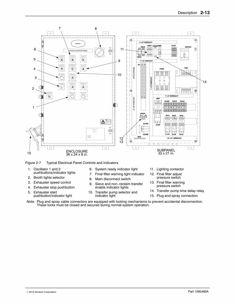
Motor Starter PanelRefer to Table 2-5 and Figure 2-7. A typical manually controlled systemuses an electrical panel similar to the panel shown in Figure 2-7. Yoursystem’s electrical panel may be different.
Table 2-5 Motor Starter Panel
Item(s) Equipment Description
2, 11 Booth light switch (2) NOTE: Power to the lights must be supplied by thecustomer.
Activates the lighting contactor (11) for interior booth lights.
7, 12, 13 Final filter pressure switches Set the pressure increase that is allowed across the finalfilters. At 2.5-in. w.c., the final filter warning pressureswitch (13) closes and activates the final filter warningindicator light (7). At 3-in. w.c., the final filter pressureswitch (12) opens and automatically shuts down thesystem.
3 Exhauster speed control Used with the variable frequency drive to adjust theexhauster fan speed.
4 Exhauster stop pushbutton NOTE: This pushbutton does not shut down power to thepanel.
Shuts down the exhauster fan and system.
10, 14 Transfer pump selector andindicator light (10)
Selects the transfer pump operation. When set to manual,the transfer pumps run continuously. When set to autofeed, the hopper level sensor and time delay relay (14)control the pump operation.
5 Exhauster startpushbutton/indicator light
Starts the exhauster fan and indicates that system power ison.
6 System ready indicator light Indicates, when lit, that the fire detection module limitswitch and air dryer interlocks are closed and that thesystem is ready to start.
8 Main disconnect switch Turns the motor starter panel electrical power on or off.
9 Sieve and non-reclaimtransfer enable indicatorlights
The sieve light indicates that the sieve is in place andrunning. The non-reclaim enabled transfer light indicatesthat the system can transfer powder without the sieve inplace.
1 Oscillator 1 and 2pushbuttons/indicator lights
Turns the oscillators on or off.
15 Plug-and-spray connection Allows for easy electrical wire connections with the flexiblemolded cables.
Description 2-13
Part 1095480A� 2010 Nordson Corporation
ENCLOSURE36 x 24 x 8 in.
SUBPANEL33 x 21 in.
Nordson�
MOTOR STARTER PANEL
G R A
AA
A
A A
1
2
3
4
5
6
7 8
9
10
11
12
14
13
OL503
M503
15
Figure 2-7 Typical Electrical Panel Controls and Indicators
6. System ready indicator light7. Final filter warning light indicator8. Main disconnect switch9. Sieve and non−reclaim transfer
enable indicator lights10. Transfer pump selector and
indicator light
11. Lighting contactor12. Final filter adjust
pressure switch13. Final filter warning
pressure switch14. Transfer pump time delay relay15. Plug-and-spray connection
Note: Plug and spray cable connectors are equipped with locking mechanisms to prevent accidental disconnection.These locks must be closed and secured during normal system operation.
Description2-14
Part 1095480A � 2010 Nordson Corporation
Pulse-Valve Timer BoxRefer to Table 2-6 and Figure 2-8. The pulse-valve timer panel houses thetimer circuit board. The panel is usually mounted on the fan section. Thetimer board is wired to the electrical panel and the pulse-valve solenoidenclosure(s) inside the fan section.
Table 2-6 Pulse Valve Timer Box
Item Equipment Description
1 Pulse valve LEDs (red) Indicate, when lit, which pulse valves are activated.
2 Electrical power LED Indicates that electrical power is applied to the board.
3 Pulse valve on timer Sets the time that the pulse valves remain open aftertriggering. The adjustment range is 0.05−0.5 sec.
4 Pulse valve off timer Sets the time between cartridge filter pulses. Theadjustment range is 8−180 sec.
5 Plug-and-spray connection Allows for easy electrical wire connections with the flexiblemolded cables.
System Pneumatic PanelTable 2-7 and Figure 2-9 describe a typical 12-function pneumatic panel.Functions can change depending on the pneumatic equipment used in thesystem and the system configuration (reclaim or non-reclaim).
Regulators and gauges are labeled according to their use. Theirassignment may vary from the example in Figure 2-9.
Table 2-7 System Pneumatic Panel
Regulatorsand Guages Function
1 Feed hopper fluidizing air
2 Feed hopper vent-assist air
3 Satellite hopper fluidizing air/spare scrap drum lid
4 Satellite hopper vent-assist air/spare scrap drum lid
14 Cartridge filter pressure gauge(shows air pressure drop across the cartridge filters inw.c.)
NOTE: The gauge should read 4−6-in. w.c. The gaugereading increases as the filters load up with powder.
15 Final filter pressure gauge
NOTE: The gauge should read 1−2.5-in. w.c. The gaugereading increases as the filters clog. At 3.0-in. wc, thesystem automatically shuts down.
Description2-16
Part 1095480A � 2010 Nordson Corporation
13
2 3 5 7 9 11
124 6 8 10
1
15 14
PNEUMATIC PANEL
Figure 2-9 System Pneumatic Panel
Rotary Sieve Control PanelSee Figure 2-10. This pneumatic panel is used with Nordson NRPS-100and AZO rotary sieves. Older Nordson rotary sieves did not have apneumatic panel.
1
2 3
1
Figure 2-10 Rotary Sieve Pneumatic Panel
1. Flow meters2. Vent-assist air regulator
3. Bearing air seal regulator
Operation 3-1
Part 1095480A� 2010 Nordson Corporation
Section 3Operation
WARNING: Allow only qualified personnel to perform the following tasks.Follow the safety instructions in this document and all other relateddocumentation.
New System Startup Use these procedures to prepare your Excel 3000 powder coating systemfor production operations. Refer to the appropriate manuals for instructionsif your system is equipped with a Smart-Spray or Smart-Coat system, oranother type of automation system.
Your Nordson Corporation representative will help you set up yourapplication equipment and adjust your system control settings before youstart powder coating your products. Record the system settings on thecharts provided at the end of this section. Make extra copies of the chartsas needed.
NOTE: Since powder coating systems are custom-designed to eachcustomer’s requirements, each system will have a different combination ofequipment. Your system may have equipment not described in this manual,such as automatic gun-triggering and air-management systems.
WARNING: Even with the electrical panel disconnect in the off position, theinput terminals at the top of the switch are still live. Do not touch them.Failure to observe this warning could result in serious injury or death.
See Figure 3-1.
Set the Timers 1. Disconnect the system electrical power and open the system electrical
panel (2).
2. Set the transfer-pump delay to 60 seconds (see Figure 2-7, (14)). Closethe electrical panel.
3. Open the pulse-valve timer panel (8). Set the pulse-valve off timer (seeFigure 2-8 (4)) to 15 seconds and the pulse valve on timer(see Figure 2-8, (3)) to duration to 0.07 seconds . Close the timer panel.
Operation3-2
Part 1095480A � 2010 Nordson Corporation
Set the Air Pressures 1. Set all air pressure regulators on the pneumatic panel (3) to zero.
2. Turn on the compressed air supply. Adjust the system air pressureto 5.5 bar (80 psi).
3. Turn on the system electrical power.
4. Use the seal control valve (6) to inflate the pneumatic seal between thecolor module and the fan section. Make sure the seal is pressingagainst the top of color module equally on all four sides
5. Turn on the exhaust fan (see Figure 2-7, (5)).
WARNING: Wear a NIOSH-approved respirator or dust mask and safetyglasses or goggles when handling powder. Avoid getting powder on yourskin. Wash powder off with soap and water only.
6. Open the feed hopper access door (5). Fill the hopper 2/3 full of powder.
7. Calibrate the feed hopper level sensor. Refer to Feed Hopper LevelSensor Calibration in this section.
8. Set the feed hopper fluidizing air pressure to 0.6 bar (8 psi). Adjust thepressure until you see the powder gently boiling. Allow 10−15 minutesfor the powder to fluidize before spraying.
9. Set the color module fluidizing air pressure to 0.7 bar (10 psi). Whenpowder covers the fluidizing plates in the bottom of the color modulehoppers, adjust the pressure. You should see the powder gently boiling.
Rotary Sieve Settings NOTE: Sieve operation depends on system configuration. In somesystems, the sieve turns on when the exhaust fan is started. In othersystems the feed hopper level-sensor signal turns on the sieve.
1. If your system uses a rotary sieve equipped with a pneumatic panel, setthe bearing air seal air pressure to 1.7 bar (25 psi) and the flow metersto 100 SCFH. See Figure 2-10.
2. If your system uses a vibratory sieve, set the air pressure to3.5 bar (50 psi). Adjust the pressure up or down to maintain the flow ofpowder through the sieve.
Operation 3-3
Part 1095480A� 2010 Nordson Corporation
Final Startup Steps 1. Set the accumulator vent-assist air pressure (5−10 psi). Refer to
Vent-Assist Air Pressure Adjustment in this section.
NOTE: When the switch is set to AUTO, the feed-hopper level sensorturns the transfer pumps on and off.
2. Set the transfer-pump air pressure to 1.0 bar (15 psi). Set thetransfer-pump selector switch to AUTO.
3. Adjust the pulse-valve air pressure and volume.
a. Open the left-hand slide gate on the front of the fan section toaccess the pulse valve air controls (7). Set the pulse valve regulatorto 3.5−4.1 bar (50−60 psi). Watch the pressure gauge. Thepressure will drop when the valves open.
b. Adjust the gate valve so the air pressure returns to3.5−4.1 bar (50−60 psi) just before the next pulse. This adjustmentwill prevent the powder pumps from being deprived of air duringpulses.
Operation3-4
Part 1095480A � 2010 Nordson Corporation
New System Startup (contd)
3
2
1
8
7
4
6
5
Figure 3-1 New System Startup
1. Flame detector indicator/relaypanel
2. Electrical panel3. Pneumatic panel
4. Sieve pneumatic panel5. Feed hopper access door6. Pneumatic seal control valve
7. Pulse air controls8. Pulse-valve timer panel
Operation 3-5
Part 1095480A� 2010 Nordson Corporation
Vent-Assist Air Pressure AdjustmentTo maintain a neutral air pressure in the sieve so it can function properly, thecompressed air used to convey the reclaimed powder to the accumulator isvented into the color module. Vent-assist air is directed through the venttube, toward the color module, to create low pressure in the tube andincrease the air flow. Use the following procedure to adjust the vent-assistair pressure.
1. Disconnect the scrap hose from the sieve.
2. Secure a paper or plastic bag to the scrap port with a worm clamp, cabletie, or rubber band.
3. Start the exhaust fan, sieve, and transfer pumps.
4. Watch the bag. If it inflates, increase the vent-assist air pressure. If itdeflates, decrease the vent-assist air pressure.
NOTE: Depending on the sieve used, the vent-assist air pressure regulatoris located either on the sieve pneumatic panel or on the system pneumaticpanel.
Feed Hopper Level Sensor Calibration The level sensor is a capacitive proximity switch. For it to function properly,you must calibrate it. This procedure must be done when you start up anew system and also when you replace a sensor.
1. See Figure 3-2. Insert the level sensor into the plastic mounting well (1)in the side of the feed hopper until it bottoms out, then tighten the plasticscrews on the side of the well to hold the sensor securely.
2. Make sure system power is on and the exhaust fan is running.
3. Open the feed hopper lid and fill the hopper 2/3 full of powder.
4. Increase the hopper fluidizing air pressure to 0.6−0.7 bar (8−10 psi).The powder level should rise above the top of the mounting well as thepowder fluidizes. Add powder to the hopper if it does not.
5. Shut off the fluidizing air. The mounting well should now be coated witha film of powder.
6. If the sensor LED (3) is on, slowly turn the sensor potentiometer (2)clockwise until it goes off. If the LED is off, slowly turn the potentiometercounterclockwise until it lights, then clockwise until it goes off.
7. Increase the fluidizing pressure until the powder level rises above themounting well. The LED should be off.
8. Turn the potentiometer counterclockwise, counting the number of turnsyou make, until the LED lights.
NOTE: Replacement sensors are shipped configured as normallyclosed (N.C.) switches.
9. Turn the potentiometer clockwise for 1/2 the number of turns youcounted in step 8. The LED will go off. The sensor is now set in themidpoint of its sensitivity range.
Operation3-6
Part 1095480A � 2010 Nordson Corporation
1
23
3.175 mm
N.O.
N.C.
L1(Vac)+ (Vdc)
1 3
2 4
L2(Vac)− (Vdc)
4
(0.125 in.)
Figure 3-2 Feed Hopper Level Sensor Calibration
1. Mounting well2. Potentiometer
3. LED4. Bridge jumper wire
Operation 3-7
Part 1095480A� 2010 Nordson Corporation
Daily Startup and Shutdown ProceduresUse these procedures for routine operation of your system.
Startup1. Turn on the system electrical power and compressed air supply.
2. Inflate the pneumatic seal between the color module and the fansection. Make sure it is sealing correctly.
3. Turn on the exhaust fan at the electrical panel.
4. Walk around the booth. Make sure the application equipment powerand air is on. Make sure the transfer and feed hoses are connected tothe pumps, accumulators, and spray guns.
5. Check all equipment ground connections.
6. Make sure the flame detector system is functioning correctly.
7. Turn on the automatic-gun master control unit and the manual-guncontrol units.
8. Adjust the kV settings and the powder-pump air pressures, if necessary.Refer to your spray gun and control unit manuals.
9. Start the conveyor and start spraying workpieces.
10. Measure the air flow velocity at the vestibules with a velometer. Thevelocity should be 30.5−36.6 m/min (100−120 ft/min). Make sure thesprayed powder is not being pulled from the spray guns and workpieces,and that the powder is not escaping from the enclosure openings.
Shutdown1. Start the transfer pumps and sieves. Pump the reclaimed powder from
the color module hoppers back into the feed hopper.
2. Turn off the automatic-gun master control unit and the manual-guncontrol units.
3. Perform the daily maintenance procedures described in theMaintenance section. Clean the powder pumps and spray guns asdescribed in their manuals. Perform daily maintenance procedures forother system equipment, as described in their manuals.
4. Turn off the exhaust fan. Shut off the system electrical power andcompressed air supply.
Operation3-8
Part 1095480A � 2010 Nordson Corporation
Changing ColorsThe following procedures describe powder color-change procedures. Usethe reclaim to non-reclaim procedure if you will not be reclaiming andreusing the new powder.
Color Change: Reclaim-to-Reclaim These instructions describe color-change procedures for reclaim systemsthat use a separate color module with attached feed hopper and sieve foreach color.
Removing the Color Module and Feed Hopper 1. Clean the enclosure as described in the Daily Maintenance procedures
in the Maintenance section. Clean the spray guns and feed hoses asdescribed in the spray gun manuals.
2. Shut off the system electrical power and compressed air supply. Relievethe system air pressure.
3. See Figure 3-3. Remove the color module quick-disconnect plates (1).Uncouple the 10-tube connectors (3) from the feed hopper receptacles.
4. If you are using a rotary sieve, disconnect the sieve electrical cablesfrom the junction boxes (6) on the fan section supports (5).
5. Rotate the level sensor (4) to unlock it from its mounting in the side ofthe feed hopper. Remove the sensor and store it on one of the fansupports.
6. Disconnect the feed hoses (7) from the powder pumps.
7. Remove the ground strap from the color module.
8. Use the seal control valve (10) to release the air pressure from thepneumatic seal (2). Make sure the seal deflates.
9. Release the clamping-strap ratchets (9) on the sides of the fan section.Disconnect the clamping straps (8) from the color module.
10. Roll the color module, feed hopper, and sieve from under the fansection. Move them to a storage area.
11. Install a storage cover on top of the color module.
Operation 3-9
Part 1095480A� 2010 Nordson Corporation
Removing the Color Module and Feed Hopper (contd)
3
2
1
8
7
4
65
9
10
Figure 3-3 Removing the Color Module and Feed Hopper
5. Fan section supports6. Junction boxes7. Feed hoses
8. Clamping straps9. Clamping strap ratchets
10. Seal control valve
Operation3-10
Part 1095480A � 2010 Nordson Corporation
Installing a New Color Module and Feed Hopper 1. See Figure 3-4. Thoroughly clean the powder off the inlet frame (3) and
surrounding area.
NOTE: If you find large amounts of powder in the fan and pulse valvecompartments, the cartridge filters are leaking. Fix the problem beforeproceeding. Refer to the Troubleshooting and Repair sections forinstructions.
2. Inspect and clean the interior of the fan section (1). Check thepneumatic seal (5), and replace it if it is damaged.
3. Remove the storage cover from the new color module (2). Inspect themodule D-gasket (6) and replace it if it is damaged.
4. Position the new color module under the fan section, against the inletframe stops.
5. Level the color module and adjust its height, if necessary, with the fourleveling screws (7) on the sides of the color module. Leave a 9−16 mm(0.375−0.625 in.) gap, equal on all sides, between the bottom of thepneumatic seal track (4) and the top of the color module (2).
NOTE: The gap allows the seal to expand when it is inflated.Powder will escape into the spray room if the gap is wider than16 mm (0.625 in.).
Operation 3-11
Part 1095480A� 2010 Nordson Corporation
Installing a New Color Module and Feed Hopper (contd)
9−16 mm(0.375−0.625in.)
1
2
3
4
5
2
6
7
Figure 3-4 Installing a New Color Module and Feed Hopper; Steps 1−5
1. Fan section2. New color module3. Inlet frame
4. Pneumatic seal track5. Pneumatic seal
6. D-gasket7. Leveling screws
Operation3-12
Part 1095480A � 2010 Nordson Corporation
NOTE: If the limit switch is not closed, you will not be able to start thesystem. Adjust the limit switch position by loosening the mounting screwsand sliding the switch forward or back.
6. See Figure 3-5. Hook the clamping straps (14) to the color module (3).Tighten the ratchets (15) to pull the color module against the stops andcompress the D-gasket against the inlet frame. This must also close thelimit switch on the inlet frame.
7. Use the seal control valve (16) to inflate the pneumatic seal (1). Makesure it is sealing on all four sides of the color module.
8. Connect the quick-disconnect plates (2) to the color module.
9. Connect the 10-tube connectors (8) to the receptacles on the feedhopper.
10. Install the level sensor (9) into the mounting on the feed hopper.
11. Make sure the accumulator (4) vent hose is connected to the vent-assistplate (6), and that the vent-assist air tubing is connected to the tubefitting.
12. Connect the sieve electrical cables to the junction boxes (12) on the fansection support.
13. Disconnect the old feed hoses (13) from the guns. Install new feedhoses between the powder pumps (10) and the guns, or use hoses thathave already been used with the new color.
14. Make sure the transfer hoses (7) are connected to the accumulator.
15. Connect all equipment ground straps and wiring.
16. Perform the Startup after Color Change procedures.
Operation 3-13
Part 1095480A� 2010 Nordson Corporation
Installing a New Color Module and Feed Hopper (contd)
3
1
2
8
7
4
6
5
9
1011
1213
1415
16
Figure 3-5 Installing a New Color Module and Feed Hopper; Steps 6−15
1. Pneumatic seal2. Quick-disconnect plates3. Color module4. Accumulator5. Transfer pumps6. Vent-assist plate
7. Transfer hoses8. 10-tube connectors9. Level sensor
10. Powder pumps11. Feed hopper
12. Junction boxes13. Feed hoses14. Clamping straps15. Clamping strap ratchets16. Seal control valve
Operation3-14
Part 1095480A � 2010 Nordson Corporation
Color Change: Reclaim to Non-ReclaimWhen you change to a powder you will not reclaim, the new powder will becollected in a new color module and pumped by the transfer pumps into ascrap drum. To supply powder to the guns, use a feed hopper attached tothe color module, or an unattached, portable feed hopper.
Systems designed to use portable feed hoppers for non-reclaimed powdershave a quick-disconnect plate mounted on a fan section support instead ofon the color module. The air tubing for the feed hopper and the the powderpumps are terminated in one or more 10-tube connectors.
New Color Module with Attached Feed Hopper� Complete all the steps under Removing Color Module and Feed Hopper.
� Perform steps 1 through 9 under Installing a New Color Module andFeed Hopper.
� Perform steps 4 through 9 under New Color Module with Portable FeedHopper.
NOTE: If the attached feed hopper is equipped with a sieve, accumulator,and level sensor, plug the ports in the accumulator after disconnecting thetransfer hoses (see Figure 3-5, (7)). Plug the level sensor mounting hole.
Operation 3-15
Part 1095480A� 2010 Nordson Corporation
New Color Module with Portable Feed Hopper� Complete all the steps under Removing Color Module and Feed Hopper.
� Perform steps 1 through 8 under Installing a New Color Module andFeed Hopper.
� Perform the following steps.
1. Block the feed-hopper vent port in the color module with a gasketedcover plate.
2. See Figure 3-5. Position the portable feed hopper so the feedhoses (13) from the powder pumps can be connected to the guns.
3. Install a vent hose between the vent on the feed hopper lid and thevent-assist plate (6) on the color module. Clamp the hose to the hoppervent and the vent-assist plate.
4. Connect air tubing to the tubing connector on the vent-assist plate.
5. Connect the 10-tube connectors to the receptacles on the fan sectionsupport.
6. Install new feed hoses (13) between the pumps and the guns. Usehoses that have already been used with the new color, if possible.
7. Install a scrap drum lid on a 55-gallon drum.
8. Connect the transfer hoses (7) from the transfer pumps (5) to the scrapdrum lid.
9. Connect the portable feed-hopper ground strap to a ground connection,such as the booth base. Make sure all other equipment ground strapsare connected.
10. Set the transfer-pump selector switch to MANUAL or OFF.
a. Set the switch to MANUAL to continuously pump the collectedpowder from the color module to the scrap drum.
b. Set the switch to OFF if you want to wait until you are done sprayingbefore you pump the powder into the scrap drum.
11. Perform the Startup after Color Change procedure.
Operation3-16
Part 1095480A � 2010 Nordson Corporation
Startup after Color Change Before starting the system, make sure all tubing, hoses, electrical cables,and ground straps have been reconnected.
1. Turn on the system electrical power and compressed air supply.
2. Rotate the seal control valve to inflate the seal. Make sure the seal ispressing against the color module equally on all four sides. Adjust theheight of the color module and level it to correct any sealing problems.
3. Start the exhaust fan.
4. Fill the feed hopper 2/3 full of powder. Adjust the hopper fluidizing-airregulator until the powder boils gently. Wait 5−10 minutes for thepowder to fluidize.
5. Start spraying parts.
6. Adjust the powder-pump air pressures and gun voltages, if necessary(different colors or powders may require different settings).
Equipment RecommendedInitial Settings Final Setting Changes
Primary Air Pressure (plant supply) 5.5 bar (80 psi)
Collector Module
#1 Fluidizing 0.7 bar (10 psi)
#2 Fluidizing 0.7 bar (10 psi)
#3 Fluidizing 0.7 bar (10 psi)
#4 Fluidizing 0.7 bar (10 psi)
#1 Transfer pump 1.7 bar (25 psi)
#2 Transfer pump 1.7 bar (25 psi)
#3 Transfer pump 1.7 bar (25 psi)
#4 Transfer pump 1.7 bar (25 psi)
Feed Hopper — Reclaim
Fluidizing 0.5 bar (8 psi)
Vent-assist 0.7 bar (10 psi)
Feed Hopper — Non-Reclaim
#1 Fluidizing 0.5 bar (8 psi)
#2 Fluidizing 0.5 bar (8 psi)
#3 Fluidizing 0.5 bar (8 psi)
Vent-assist 0.7 bar (10 psi)
Pulse Manifold
Air pressure 3.5−4.1 bar(50−60 psi)
Nordson NFS-1000 Fire Detector
Air pressure 0.7 bar (10 psi)(preset)
Continued...
Operation 3-17
Part 1095480A� 2010 Nordson Corporation
Startup after Color Change (contd)
Equipment RecommendedInitial Settings Final Setting Changes
Rotary Sieve
Flowmeter #1 2.8 m3/h(100 SCFH)
Flowmeter #2 2.8 m3/h(100 SCFH)
Seal air pressure 1.7 bar (25 psi)
Vent-assist air pressure 2.8 bar (40 psi)
Vibratory Sieve
Air pressure 3.5 bar (50 psi)
Pulse Timer
Delay (OFF) time 15.0 sec
Duration (ON) time 0.07 sec
Filter Pressure Drop MaximumReadings
Cartridge filters 4−6 in. w.c.
Final filters 2 in. w.c.
Automatic Guns
#1 Flow-rate 2.1 bar (30 psi)
Atomizing 1.4 bar (20 psi)
Voltage 90−100 kV
AFC 40 A
#2 Flow-rate 2.1 bar (30 psi)
Atomizing 1.4 bar (20 psi)
Voltage 90−100 kV
AFC 40 A
#3 Flow-rate 2.1 bar (30 psi)
Atomizing 1.4 bar (20 psi)
Voltage 90−100 kV
AFC 40 A
#4 Flow-rate 2.1 bar (30 psi)
Atomizing 1.4 bar (20 psi)
Voltage 90−100 kV
AFC 40 A
#5 Flow-rate 2.1 bar (30 psi)
Atomizing 1.4 bar (20 psi)
Voltage 90−100 kV
AFC 40 A
Continued...
Operation3-18
Part 1095480A � 2010 Nordson Corporation
Equipment RecommendedInitial Settings Final Setting Changes
#6 Flow-rate 2.1 bar (30 psi)
Atomizing 1.4 bar (20 psi)
Voltage 90−100 kV
AFC 40 A
#7 Flow-rate 2.1 bar (30 psi)
Atomizing 1.4 bar (20 psi)
Voltage 90−100 kV
AFC 40 A
#8 Flow-rate 2.1 bar (30 psi)
Atomizing 1.4 bar (20 psi)
Voltage 90−100 kV
AFC 40 A
#9 Flow-rate 2.1 bar (30 psi)
Atomizing 1.4 bar (20 psi)
Voltage 90−100 kV
AFC 40 A
#10 Flow-rate 2.1 bar (30 psi)
Atomizing 1.4 bar (20 psi)
Voltage 90−100 kV
AFC 40 A
#11 Flow-rate 2.1 bar (30 psi)
Atomizing 1.4 bar (20 psi)
Voltage 90−100 kV
AFC 40 A
#12 Flow-rate 2.1 bar (30 psi)
Atomizing 1.4 bar (20 psi)
Voltage 90−100 kV
AFC 40 A
#13 Flow-rate 2.1 bar (30 psi)
Atomizing 1.4 bar (20 psi)
Voltage 90−100 kV
AFC 40 A
#14 Flow-rate 2.1 bar (30 psi)
Atomizing 1.4 bar (20 psi)
Voltage 90−100 kV
AFC 40 A
Continued...
Operation 3-19
Part 1095480A� 2010 Nordson Corporation
Startup after Color Change (contd)
Equipment RecommendedInitial Settings Final Setting Changes
#15 Flow-rate 2.1 bar (30 psi)
Atomizing 1.4 bar (20 psi)
Voltage 90−100 kV
AFC 40 A
#16 Flow-rate 2.1 bar (30 psi)
Atomizing 1.4 bar (20 psi)
Voltage 90−100 kV
AFC 40 A
#17 Flow-rate 2.1 bar (30 psi)
Atomizing 1.4 bar (20 psi)
Voltage 90−100 kV
AFC 40 A
#18 Flow-rate 2.1 bar (30 psi)
Atomizing 1.4 bar (20 psi)
Voltage 90−100 kV
AFC 40 A
#19 Flow-rate 2.1 bar (30 psi)
Atomizing 1.4 bar (20 psi)
Voltage 90−100 kV
AFC 40 A
#20 Flow-rate 2.1 bar (30 psi)
Atomizing 1.4 bar (20 psi)
Voltage 90−100 kV
AFC 40 A
#21 Flow-rate 2.1 bar (30 psi)
Atomizing 1.4 bar (20 psi)
Voltage 90−100 kV
AFC 40 A
#22 Flow-rate 2.1 bar (30 psi)
Atomizing 1.4 bar (20 psi)
Voltage 90−100 kV
AFC 40 A
#23 Flow-rate 2.1 bar (30 psi)
Atomizing 1.4 bar (20 psi)
Voltage 90−100 kV
AFC 40 A
Continued...
Operation3-20
Part 1095480A � 2010 Nordson Corporation
Equipment RecommendedInitial Settings Final Setting Changes
#24 Flow-rate 2.1 bar (30 psi)
Atomizing 1.4 bar (20 psi)
Voltage 90−100 kV
AFC 40 A
#25 Flow-rate 2.1 bar (30 psi)
Atomizing 1.4 bar (20 psi)
Voltage 90−100 kV
AFC 40 A
#26 Flow-rate 2.1 bar (30 psi)
Atomizing 1.4 bar (20 psi)
Voltage 90−100 kV
AFC 40 A
#27 Flow-rate 2.1 bar (30 psi)
Atomizing 1.4 bar (20 psi)
Voltage 90−100 kV
AFC 40 A
#28 Flow-rate 2.1 bar (30 psi)
Atomizing 1.4 bar (20 psi)
Voltage 90−100 kV
AFC 40 A
Maintenance 4-1
Part 1095480A� 2010 Nordson Corporation
Section 4Maintenance
WARNING: Allow only qualified personnel to perform the following tasks.Follow the safety instructions in this document and all other relateddocumentation.
Daily MaintenancePerform these procedures daily to keep your system clean and functioningproperly.
CleaningPerform this procedure daily and when changing powder color or type.
WARNING: Wear an approved respirator and safety glasses or goggleswhen handling powder, operating spray equipment, or performingmaintenance or cleaning operations. Obtain and read Material Safety DataSheets for each powder used.
1. Turn off the automatic-gun master-control unit(s) and manual-guncontrol units.
2. Turn on the exhaust fan.
3. Disconnect the powder-feed hoses from the powder pumps. Blow thepowder out of the hoses and spray guns with compressed air.
4. Ground the gun electrodes and clean the spray guns according to theinstructions in the gun manuals.
5. Clean the enclosure roof, walls, and floor with a rubber squeegee. Pushthe collected powder into the color module.
6. Remove the remaining powder residue from the enclosure with anair-powered vacuum and a soft brush attachment. Wipe down allsurfaces with a damp, lint-free cloth (do not use tack cloths). If youremove the color module, clean the inlet frame and surrounding area.
7. Turn off the exhaust fan.
8. Clean the operator’s platform and the floor around the booth.
Maintenance4-2
Part 1095480A � 2010 Nordson Corporation
Daily Equipment MaintenanceEquipment Procedure
Filters — Check the differentialpressure gauges.
1. Check the final filter differential pressure gauge. It shouldread between 1 and 2.5 in. of water (wc). Make sure nopowder is leaking from around the filter gasket or face.
2. Check the cartridge filter differential pressure gauge. Itshould read between 4 and 6 in. of water (wc). Check thepulse valve timing.
Vibratory Sieve Open the hopper lid and remove the screen from the sieve.Clean the screen and replace it if it is damaged. Reconnect theground clip to the screen after reinstalling it.
Rotary Sieves — Clean 1. Empty the scrap pail.
2. Open the sieve housing and clean the rotor and screen with asoft brush. Replace the screen if it is damaged.
3. Check the seal air pressure and flow rate. Check thevent-assist air pressure. Refer to your sieve manual for moreinformation.
Transfer Pumps 1. Disconnect the transfer hoses from the pumps. Blow thepowder out of the hoses with compressed air.
2. If the pumps are installed horizontally, place a small containerunder the transfer pumps to catch spilled powder. Removethe pumps from the adapters. Blow out the adapters.
3. Disassemble the pumps. Clean the parts with a low-pressureair gun and a clean cloth. Replace any worn or damagedparts.
Fan Section 1. Remove the final filters and inspect the fan compartment.Vacuum out any powder.
2. Inspect the pulse-valve compartment. Vacuum out anypowder. If significant amounts of powder have accumulatedin the fan or pulse-valve compartment, the cartridge filtersmay be leaking. Refer to the Troubleshooting section forinstructions.
3. Inspect the V-belts. Replace cracked or worn belts.
Powder Spray Guns Disassemble and clean the spray guns according to theinstructions in their manuals.
Powder Pumps Disassemble and clean the pumps according to the instructionsin their manuals. Replace worn parts.
Flame Detector System Check the detector sensors every four hours and clean thelenses, if necessary. Make sure air is being supplied to thesensors. Make sure the detector system is operating properly.
Compressed Air Supply Hold a clean, white cloth under the drop leg and open thedrop-leg drain valve. Water, oil, or other contaminants will stainthe cloth. Eliminate any source of contamination. Drain thefilters and separators and check the filter elements. Check all airpressure regulator settings.
NOTE: The air dryer should remain on at all times to preventmoisture from accumulating in the compressed air system.
Continued...
Maintenance 4-3
Part 1095480A� 2010 Nordson Corporation
Equipment Procedure
Air Dryers Refer to your air dryer manual for maintenance procedures andschedules.
Gun Movers (Oscillators andReciprocators)
Each shift, make sure the gun movers are stroking smoothly andat the proper speed. Make repairs and adjustments if necessary.Lubricate the spray gun movers as described in their manuals.
Accumulators and Vent Hoses Vacuum out the accumulators and blow the powder out of thevent hoses with compressed air.
Workpiece and Conveyor Grounds WARNING: An ungrounded or poorlygrounded workpiece, hanger, or conveyor cancause electrical arcing. If arcing is observed,shut down the system immediately. Correct thecause before resuming operations. Failure toobserve this warning could result in a fire orexplosion, causing property damage andpossible personal injury or death.
Make sure all workpieces are grounded through the hangers andconveyor. The resistance between the workpieces and thehangers, and the hangers and ground, must be less than1 megohm. You will get better transfer efficiency and workpiececoverage at 500 ohms or less. Clean or strip the hangersregularly.
Maintenance4-4
Part 1095480A � 2010 Nordson Corporation
Weekly MaintenanceEquipment Procedure
Booth Enclosure Turn on the exhaust fan and vacuum the enclosure roof, walls,and floor with a soft brush attachment. Wipe down the enclosurewith damp, lint-free cloths. Clean the booth exterior, all attachedequipment, and the spray room.
Powder Spray Guns and Cables Clean the spray guns. Perform electrostatic resistance checksas described in the spray gun and gun control unit (electrostaticpower supply) manuals.
Powder Pumps and Feed Hoses Disassemble the pumps and clean them according to theinstructions in their manuals. Replace any worn or damagedparts. Blow out the feed hoses with compressed air. Replacedamaged hoses.
Feed Hoppers Remove the powder from the hopper. Vacuum the interior.Check the fluidizing plate. If the plate is stained, the air supplycould be contaminated by oil or moisture. Check the air dryerand air filters. Replace the fluidizing plate if it is contaminated.
Lubricate the casters with a lithium grease.
Color Module Start the exhaust fan and activate the pulse valves to blow off asmuch powder as possible off the cartridge filters. Do not vacuumthe cartridge filters. Remove the cartridge filters and inspect thefilter media and gaskets. Replace the filters if they are damaged.
Pump the powder out of the color module. Disconnect the hosesfrom the transfer pumps. Blow the powder out of the hoses withcompressed air. Remove the transfer pumps and clean them asdescribed in their manuals.
Vacuum the color module interior. Check the color modulehopper fluidizing plates. If they are stained, the air supply couldbe contaminated by oil or moisture. Check the air dryer and airfilters. Replace the fluidizing plates if they are contaminated.
Check the pneumatic seal. Make sure it seals correctly wheninflated.
Lubricate the casters with a lithium grease.
Maintenance 4-5
Part 1095480A� 2010 Nordson Corporation
Periodic MaintenanceEquipment Procedure
Electrical Connections Check all terminal blocks, and junction boxes for loose wires.Tighten any loose connections and inspect all wiring fordamaged insulation. Replace the wiring if the insulation isdamaged.
Guns and Cables Perform electrostatic resistance checks as described in the spraygun and gun control unit manuals.
Air Dryer Check the air dryer operation. Refer to your air dryer manual formaintenance procedures and schedules.
Gaskets Inspect all gaskets and seals for damage. Replace them if theyare damaged.
Exhaust Fan V-belts Every six months, adjust the tension of the exhaust fan V-belts.You should not be able to deflect the belts more than 19 mm(0.75 in.) (one belt diameter).
Bearings Every six months, lubricate the fan shaft and motor bearings withtwo shots of lithium or polyurea grease from a grease gun. Thegrease fittings are on the front face of the fan section.
AZO Rotary Sieve Every three months, lubricate the lip seals with a white lithiumgrease as described in your AZO sieve manual.
Differential Pressure Gauges Observe and record the differential pressure gauges. Readingsgreater than the following mean that the filters are clogged andmust be replaced. Correct the cause of the clogging beforeresuming operations.
Pressure drop across cartridge filters: 4−6 in. wc.
Pressure drop across final filters: 2 in. wc.
Powder Feed Hoses Disconnect the powder feed hoses from the powder pumps.Blow the powder out of the hoses with compressed air. Neverblow air through the hoses toward the pumps. Replace thehoses if they are clogged with impact-fused powder.
Maintenance4-6
Part 1095480A � 2010 Nordson Corporation
Maintenance Check ListActivity Each
Shift Daily Weekly Monthly ColorChange
Cleaning
Accumulator �
Booth enclosure � � �
Color module � �
Fan and pulse-valve compartments � �
Feed hoses and transfer hoses � �
Fire detector head lenses* � �
Gun pumps � � � �
Guns � � �
Rotary sieve � �
Transfer pumps � � �
Vent hoses � �
Vibratory sieve � �
Resistance Checks—Guns and Cables �
Visual Checks
Air supply drop leg �
Air dryer �
Cartridge filter differential-pressure gauge �
Electrical connections �
Exhaust fan V-belts �
Final filter differential-pressure gauge �
Fire detector sensors � �
Gaskets �
Gun movers �
Workpiece clearance** �
Workpiece grounding � �
Powder levels �
Lubrication
AZO rotary-sieve lip seals*** �
Fan bearings �
Motor bearings �
* Every 4 hours.
** Clearances should be monitored continuously.
*** Every 3 months.
Troubleshooting 5-1
Part 1095480A� 2010 Nordson Corporation
Section 5Troubleshooting
WARNING: Allow only qualified personnel to perform the following tasks.Follow the safety instructions in this document and all other relateddocumentation.
Introduction This section contains troubleshooting procedures. These procedures coveronly the most common problems that you may encounter. If you cannotsolve the problem with the information given here, contact your localNordson representative for help.
No. Problem Page
1. Spray guns are surging or spitting; powder flow isinadequate or intermittent
5-2
2. Problems with coating uniformity, edge coverage, filmbuild, wrap, or penetration into recesses
5-2
3. Powder not transferring from color module to feedhopper
5-3
4. Powder not fluidizing, or clouds of powder eruptingfrom surface
5-4
5. Final filters clogged; powder in fan compartment 5-4
6. Cartridge filters clogged 5-5
7. System shuts down or will not start 5-5
8. Sieve not screening powder 5-5
9. Sieve scrap bucket filling up with powder 5-6
10. Powder escaping from booth openings 5-6
NOTE: To troubleshoot electrical problems, refer to the wiring and controlpanel foldouts at the back of this manual.
Troubleshooting5-2
Part 1095480A � 2010 Nordson Corporation
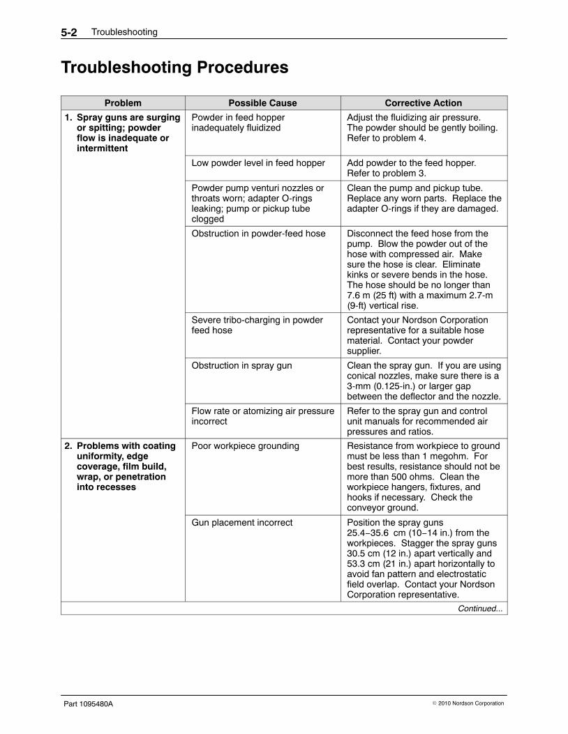
Troubleshooting Procedures
Problem Possible Cause Corrective Action
1. Spray guns are surgingor spitting; powderflow is inadequate orintermittent
Powder in feed hopperinadequately fluidized
Adjust the fluidizing air pressure.The powder should be gently boiling.Refer to problem 4.
Low powder level in feed hopper Add powder to the feed hopper.Refer to problem 3.
Clean the pump and pickup tube.Replace any worn parts. Replace theadapter O-rings if they are damaged.
Obstruction in powder-feed hose Disconnect the feed hose from thepump. Blow the powder out of thehose with compressed air. Makesure the hose is clear. Eliminatekinks or severe bends in the hose.The hose should be no longer than7.6 m (25 ft) with a maximum 2.7-m(9-ft) vertical rise.
Severe tribo-charging in powderfeed hose
Contact your Nordson Corporationrepresentative for a suitable hosematerial. Contact your powdersupplier.
Obstruction in spray gun Clean the spray gun. If you are usingconical nozzles, make sure there is a3-mm (0.125-in.) or larger gapbetween the deflector and the nozzle.
Flow rate or atomizing air pressureincorrect
Refer to the spray gun and controlunit manuals for recommended airpressures and ratios.
2. Problems with coatinguniformity, edgecoverage, film build,wrap, or penetrationinto recesses
Poor workpiece grounding Resistance from workpiece to groundmust be less than 1 megohm. Forbest results, resistance should not bemore than 500 ohms. Clean theworkpiece hangers, fixtures, andhooks if necessary. Check theconveyor ground.
Gun placement incorrect Position the spray guns25.4−35.6 cm (10−14 in.) from theworkpieces. Stagger the spray guns30.5 cm (12 in.) apart vertically and53.3 cm (21 in.) apart horizontally toavoid fan pattern and electrostaticfield overlap. Contact your NordsonCorporation representative.
Continued...
Troubleshooting 5-3
Part 1095480A� 2010 Nordson Corporation
Problem Possible Cause Corrective Action
2. Problems with coatinguniformity, edgecoverage, film build,wrap, or penetrationinto recesses (contd)
Powder pump flow rate andatomizing air pressure incorrect
Refer to the spray gun and controlunit manuals for the recommendedair pressures and ratios.
Electrostatic voltage (kV) or AFCsetting incorrect for workpiecesbeing coated
Adjust the voltage to 90−100 kV forlarge flat surfaces and 60−75 kV forrecesses. Never set the voltagebelow 60 kV. Refer to the spray gunand control unit manuals for therecommended voltage, AFC, and airpressure settings and ratios.
Wrong nozzles being used Use flat-spray nozzles for largeregular-shaped workpieces. Useconical nozzles for deep recessesand most manual touch-ups.
Powder feed problems Refer to problem 1.
3. Powder nottransferring from colormodule to feed hopper
Transfer pump air pressure too low Increase the air pressure.
Transfer pump clogged or venturinozzle or throat worn
Clean the pump and replace wornparts.
Transfer hose plugged Blow the powder out of the hose withcompressed air.
Sieve screens clogged, or motorrunning in wrong direction
Clean the sieve screens. Refer tothe Reversing Motor Directionprocedure in this section.
Accumulator plugged Clean out the inlet ports. Clean theaccumulator interior.
Accumulator vent-assist airpressure too high
Reduce the vent-assist air pressure.
Powder in color module notfluidized. Deep hole in powderaround pickup tube
Increase the fluidizing pressure. Ifthe problem continues, go to the nextcause.
Powder damp or contaminated;cannot be fluidized or pumped
Refer to problem 4.
Continued...
Troubleshooting5-4
Part 1095480A � 2010 Nordson Corporation
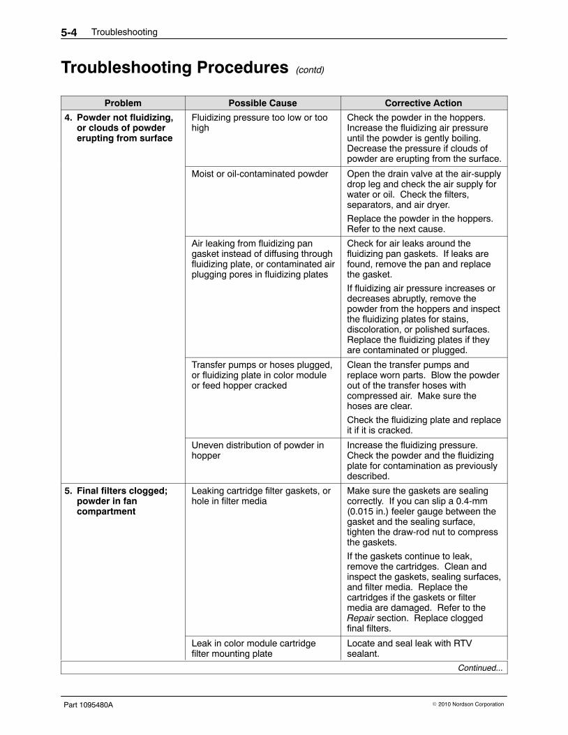
Troubleshooting Procedures (contd)
Problem Possible Cause Corrective Action
4. Powder not fluidizing,or clouds of powdererupting from surface
Fluidizing pressure too low or toohigh
Check the powder in the hoppers.Increase the fluidizing air pressureuntil the powder is gently boiling.Decrease the pressure if clouds ofpowder are erupting from the surface.
Moist or oil-contaminated powder Open the drain valve at the air-supplydrop leg and check the air supply forwater or oil. Check the filters,separators, and air dryer.
Replace the powder in the hoppers.Refer to the next cause.
Air leaking from fluidizing pangasket instead of diffusing throughfluidizing plate, or contaminated airplugging pores in fluidizing plates
Check for air leaks around thefluidizing pan gaskets. If leaks arefound, remove the pan and replacethe gasket.
If fluidizing air pressure increases ordecreases abruptly, remove thepowder from the hoppers and inspectthe fluidizing plates for stains,discoloration, or polished surfaces.Replace the fluidizing plates if theyare contaminated or plugged.
Transfer pumps or hoses plugged,or fluidizing plate in color moduleor feed hopper cracked
Clean the transfer pumps andreplace worn parts. Blow the powderout of the transfer hoses withcompressed air. Make sure thehoses are clear.
Check the fluidizing plate and replaceit if it is cracked.
Uneven distribution of powder inhopper
Increase the fluidizing pressure.Check the powder and the fluidizingplate for contamination as previouslydescribed.
5. Final filters clogged;powder in fancompartment
Leaking cartridge filter gaskets, orhole in filter media
Make sure the gaskets are sealingcorrectly. If you can slip a 0.4-mm(0.015 in.) feeler gauge between thegasket and the sealing surface,tighten the draw-rod nut to compressthe gaskets.
If the gaskets continue to leak,remove the cartridges. Clean andinspect the gaskets, sealing surfaces,and filter media. Replace thecartridges if the gaskets or filtermedia are damaged. Refer to theRepair section. Replace cloggedfinal filters.
Leak in color module cartridgefilter mounting plate
Locate and seal leak with RTVsealant.
Continued...
Troubleshooting 5-5
Part 1095480A� 2010 Nordson Corporation
Corrective ActionPossible CauseProblem
6. Cartridge filtersclogged
Pulse air pressure inadequate Increase the pulse air pressure orvolume. Decrease the pulse timerdelay (off time).
Powder too fine or contaminated Reduce the ratio of reclaim-to-newpowder. Check the powder particlesize. Replace contaminated powderand fix the source of contamination.
Pulse valves out of position Position the valves as described inthe Repair section.
Timer board settings incorrect Adjust the timer board settings asdescribed in the Operation section.
Pulse valve or solenoid valvesclogged or malfunctioning
Open the pulse valve timer panel. Ifyou do not hear a pulse each time anLED lights, the solenoid valve or thepulse valve connected to that LEDmay be clogged or failed. Check thewiring to the solenoid valve beforeopening the solenoid box andreplacing the solenoid valve.
7. System shuts down orwill not start
Flame detector system sees aflame or spark, or is malfunctioning
Check the inside of the enclosureand color module, the detector headaim, and the workpiece and conveyorgrounds.
Follow the troubleshootingprocedures in the flame detectorsystem manual.
Final filters clogged Locate the source of powder leakageand correct the problem. Refer toproblem 5.
Color module not activating limitswitch
Tighten the color module clampingstraps, or reposition the limit switcharm. If the problem continues,replace the limit switch.
Final filter pressure switch failed Replace the switch.
Air dryer not operating, or interlocknot activated
Start the air dryer. Follow thetroubleshooting procedures in thedryer manual. Check the interlockcircuit.
Fuse(s) blown Check the fuses in the systemelectrical panel. Replace the blownfuse(s). If the fuses continue to blow,fix the electrical problem.
Electrical failure Trace the circuits and correct theproblem.
8. Sieve not screeningpowder
Screen clogged or damaged Clean or replace the screen.
Continued...
Troubleshooting5-6
Part 1095480A � 2010 Nordson Corporation
Troubleshooting Procedures (contd)
Problem Possible Cause Corrective Action
9. Sieve scrap bucketfilling up with powder
Scrap bucket lid not sealed The lid must be air-tight. Tighten thelid. Check the scrap hoseconnections.
Screen clogged Clean or replace the screen.
10. Powder escapingfrom booth openings
Cartridge filters clogged If the differential pressure gaugeshows more than 6 in. wc, refer toproblem 6.
Cross drafts interfering withexhaust fan draw
Check for cross drafts at all of theenclosure openings. Eliminate ordivert any drafts.
Workpieces entering booth are toohot
Cool the workpieces beforemoving them into the booth. Theworkpiece temperature shouldnot exceed 49 �C (120 �F).
Reduce the powder flow and/or thenumber of the spray guns.
Booth openings too large Close or decrease the size of theopenings.
Workpieces too large for booth Contact your Nordson Corporationrepresentative.
Spray guns too close to entranceand exit vestibules or openings
Move the spray guns farther awayfrom the vestibules or openings.
Fan rotation backward Reverse the rotation of the motor.Refer to Reversing Motor Direction inthis section.
Air leaks around color module Inspect the D-gasket and replace it ifit is damaged. Tighten the clampingstraps to compress the D-gasket.
Check the pneumatic seal. Makesure it is inflated, and sealingproperly around all four sides. Referto Installing a New Color Module andFeed Hopper in the Operationsection. Replace the seal if it isdamaged.
Reversing Motor DirectionImproperly connecting the exhaust fan and sieve motor starters will causethem to rotate in the wrong direction. If the exhaust fan is rotating in thewrong direction, powder will be blown out of the enclosure. If the sieverotates in the wrong direction, powder will back up in the accumulator. Usethe following procedures to check and correct, if necessary, the exhaust fanand sieve motor rotation direction.
Troubleshooting 5-7
Part 1095480A� 2010 Nordson Corporation
Exhaust Fan Motor1. Turn on system electrical power.
2. Start the exhaust fan motor.
3. Observe the direction of fan rotation. The fan should rotate in thedirection indicated by the yellow arrow on the front of the fan section.The fan shaft should rotate clockwise when viewed from the sheave(pulley) end (from above the fan). If the rotation is backward, go to thenext step.
WARNING: Even with the electrical panel disconnect in the off position, theinput terminals at the top of the switch are still live. Do not touch them.Failure to observe this warning could result in serious injury or death.
4. Shut off system electrical power. Open the electrical panel door andreverse any two wires (L1, L2, or L3) connected to the fan motor starter(M407). Close the electrical panel door.
5. Turn on electrical power. Start the fan and check the rotation direction.
Sieve Motor1. Check your sieve manual for the proper motor rotation direction. If it is
rotating in the wrong direction, perform the next step.
WARNING: Even with the electrical panel disconnect in the off position, theinput terminals at the top of the switch are still live. Do not touch them.Failure to observe this warning could result in serious injury or death.
2. Shut off system electrical power. Open the electrical panel door.Reverse any two wires (L1, L2, or L3) connected to the sieve motorstarter (M412). Close the electrical panel door.
3. Restore system electrical power. Start the sieve and check the rotationdirection.
Troubleshooting5-8
Part 1095480A � 2010 Nordson Corporation
Repair 6-1
Part 1095480A� 2010 Nordson Corporation
Section 6Repair
WARNING: Allow only qualified personnel to perform the following tasks.Follow the safety instructions in this document and all other relateddocumentation.
Final Filter Replacement WARNING: Before performing this procedure, shut off electrical power atthe system electrical panel. Lock and tag the switch. Failure to observethis warning could result in personal injury or death.
1. Shut off the exhaust fan. Shut off electrical power at the systemelectrical panel. Lock and tag the disconnect switch.
2. See Figure 6-1. Unscrew and remove the threaded knobs (3) andbrackets (2) securing the final filters (1) to the fan section. The filters willstay in place.
3. Remove the old filters and discard them.
4. Check the interior of the fan housing. If you see large amounts ofpowder inside the housing, powder is leaking through the cartridge filtersor mounting plate. Fix the leak before starting the system.
NOTE: Do not use damaged filters.
5. Remove the new filters from their cartons. Inspect the filter housings,gaskets, and media for damage.
6. Insert the new filters into the openings.
7. Install the brackets over the threaded studs. Thread the knobs onto thestuds.
8. Tighten the knobs to compress the filter gaskets slightly. Do notovertighten the knobs.
9. Restore system electrical power. Start the exhaust fan and check forleaks around the filter gaskets.
Repair6-2
Part 1095480A � 2010 Nordson Corporation
Final Filter Replacement (contd)
1
23
Figure 6-1 Final Filter Replacement
1. Final filter 2. Brackets 3. Threaded knobs
Cartridge Filter Replacement Remove the color module from under the fan section as described in theReclaim-to-Reclaim Color Change procedure in the Operation section.
CAUTION: Do not use any cartridge filters other than those specified foryour system. Using unapproved cartridge filters could seriously affect theoperation and performance of your system, as well as void FM approvals.Do not use damaged filters.
Carefully inspect new cartridge filters for
� cuts or other damage to the rubber gaskets.
� bent or dented end caps.
� holes or other damage to the filter media.
Repair 6-3
Part 1095480A� 2010 Nordson Corporation
36-in. Cartridge Filter Replacement 1. See Figure 6-2. Remove the baffle (2).
2. Pull up on the T-handles on the draw rods (6) to hold the cartridgefilters (7) against the tube sheet (1).
3. Remove the nuts (3) and filter mounts (4) from the draw rods. Save theremoved parts.
4. Remove the cartridge filters (7) from the color module.
5. Unscrew the draw rods from the cartridge filter bosses and remove thefilter centering brackets (5) and draw rods from the cartridge filters.Save the draw rods and centering brackets for reuse.
6. Thoroughly clean the sealing surfaces on the underside of the mountingplate (1). Dirty surfaces will prevent the cartridge filter gaskets fromsealing properly and allow powder to leak into the fan section.
7. Insert the threaded end of the draw rods (5) through the centeringbrackets (4), then install them into the filters and screw the ends of thedraw rods into the filter bosses, tightening the rods by hand.
8. Hold the cartridge filters up against the tube sheet, centered under thefilter openings.
9. Use the T-handles to pull the cartridge filters up against the filtermounting plates. Install the filter mounts (3) on the draw rods, makingsure the slots in the filter mounts slip over the T-handles.
10. Install nuts (2) on the draw rods.
11. Slip the ends of the filter mounts into the locating slots in the mountingplate, around the openings.
CAUTION: Do not overtighten the nuts, or you may damage the cartridgefilters.
12. Tighten the nuts until the filter mounts and centering brackets aretouching. This will compress the filter gaskets (8) and seal thecartridges against the mounting plate.
13. Install the color module as described in Installing a New Color Moduleand Feed Hopper in the Operation section.
Repair6-4
Part 1095480A � 2010 Nordson Corporation
36-in. Cartridge Filter Replacement (contd)
3
4
5
6
7
2
4
1
8
7
5
6
1
1
Figure 6-2 36-in Cartridge Filter Replacement
1. Tube sheet2. Baffle3. 5/8−11 nut
4. Filter mount5. Centering bracket6. Draw rod
7. Closed-end filter cartridge8. Filter gasket
26-in. Filter Cartridge Replacement 1. See Figure 6-3. Remove the baffle (2). Support the filter stack while
performing the next step.
2. Remove the 3/8−16 jam nut (3), the compression nut (4), the 5/8−16 jamnut (5), and the filter mount (7). Save the removed parts.
3. Remove the filter stack from the color module.
4. Lift the open end filter and threaded tube off the threaded rod.
5. Remove the threaded tube and centering brackets from the open-endfilter. Leave the jam nut and bottom centering bracket on the threadedrod.
6. Unscrew the threaded rod from the closed-end filter boss and install itand the centering bracket in the new closed-end filter.
7. Install the threaded tube and bottom centering bracket through thebottom of the open-end filter.
8. Lift the open-end filter assembly and guide the thread rod into thethreaded tube, until the two filters are touching and centered.
9. Install the top centering bracket over the threaded rod and tube.
Repair 6-5
Part 1095480A� 2010 Nordson Corporation
10. Install the filter assembly into the color module, and hold it up againstthe tube sheet over the opening.
CAUTION: Do not overtighten the jam nuts, or you may damage thecartridge filters.
11. Install the filter mount over the threaded tube, then install the 5/8−16 jamnut on the threaded rod and tighten until the top filter gasket iscompressed against the tube sheet.
12. Install the compression nut on the threaded tube and tighten.
13. Install the 3/8−16 jam nut on the threaded rod and tighten to compressthe filter gaskets.
1. Tube sheet2. Baffle3. 3/8−16 jam nut4. Compression nut
5. 5/8−16 jam nuts6. Threaded rod7. Filter mount8. Threaded tube
9. Centering bracket10. Open-end 26 in. filter11. Closed-end 26 in. filter12. Filter gasket
Repair6-6
Part 1095480A � 2010 Nordson Corporation
Color Module Fluidizing Plate ReplacementFluidizing plate replacement will only be necessary if the plates arecontaminated or damaged.
Preparation1. Start the transfer pumps and pump as much as possible of the powder
in the color module hoppers back into the feed hopper. If the powder iscontaminated, pump it into a scrap bucket.
2. Remove the color module from under the fan section as described in theReclaim-to-Reclaim Color Change procedure in the Operation section.
3. Remove the baffle, transfer pumps, and cartridge filters from the colormodule.
4. Remove all the powder from the color module hoppers. Vacuum thehoppers and fluidizing plates and wipe them clean with damp, lint-freecloths. Do not use tack cloths.
Replacement
WARNING: Heavy equipment. Use approved, inspected lifting equipmentand tackle. Make sure the capacity of the lifting equipment and tackleexceeds the weight of the equipment being lifted.
1. Use a forklift truck or suitable jacks to raise the color module severalfeet off the floor. Install safe, solid, support blocks under the module,then lower the module onto the blocks.
2. See Figure 6-4. Unscrew the clamping-channel screws (6) about6−10 mm (0.25−0.375 in.) to clear the fluidizing plate gaskets (2).Support the fluidizing plenums (4) and remove the clampingchannels (5).
3. Remove the fluidizing plenums from under the color module.
4. Separate the old fluidizing plates (1), gaskets (2), and diffuser plates (3).Discard the old fluidizing plates.
5. Clean the plenums, diffuser plates, and hopper flanges.
6. Assemble the fluidizing plenums, diffuser plates, gaskets, and fluidizingplates as shown in Figure 6-4. Install the diffuser plates between thegaskets and the fluidizing plates.
7. Hold the plenum assemblies in position against the color modulehoppers. Install the clamping channels over the fluidizing plenums andhopper flanges. Align the plenum and hopper flanges on all four sides.
8. Tighten the clamping-channel screws with a torque wrench to 2.8 N�m(25 in.-lb) in a criss-cross pattern This will prevent flange distortion andfluidizing plate damage.
9. Lower the color module to the floor and install the cartridge filters,transfer pumps, and baffle. Roll the color module into position under thefan section. Connect the hoses, quick disconnects, tubing, power cords,and level sensor.
Repair 6-7
Part 1095480A� 2010 Nordson Corporation
6
1
4
3
5
2
6
5
4
3
2
1
Figure 6-4 Typical Color Module Fluidizing Plate Replacement
1. Fluidizing plates2. Fluidizing plate gaskets
3. Diffuser plates4. Fluidizing plenums
5. Clamping channels6. Clamping-channel screws
Repair6-8
Part 1095480A � 2010 Nordson Corporation
Feed Hopper Fluidizing Plate ReplacementFollow these instructions to replace the feed hopper fluidizing plate.
Preparation1. Pump as much powder as you can from the feed hopper. Disconnect
the powder feed hoses, transfer hoses, accumulator vent hose, and10-tube quick-disconnects from the feed hopper, powder pumps, andaccumulator.
2. Rotate the level sensor and pull it from its mounting in the side of thefeed hopper.
3. Unplug the sieve power cords (electrically driven sieves only).Disconnect the feed-hopper ground wire.
4. Remove the feed hopper from the color module and roll it to a cleanwork area.
5. Remove the powder from the hopper and thoroughly clean the hopper,accumulator, and sieve.
Replacement1. See Figure 6-5. Block up the plenum (5) so the plenum and feed
hopper flanges will not bend when you start removing the clampingchannels (3).
2. Loosen screws (4) about 6−10 mm (0.25−0.375 in.) to clear thegasket (2). Remove the clamping channels.
3. Remove the plenum and the fluidizing plate (1) from under the feedhopper.
4. Clean the plenum interior and the plenum and feed hopper flanges.
5. Position the new fluidizing plate and gasket on the plenum.
6. Slide the plenum and fluidizing plate under the hopper. Align the edgesof the feed hopper flange, gasket, and plenum flange evenly on allsides. Block the plenum to hold it in position.
7. Install the clamping channels over the plenum and hopper flanges.Tighten the clamping-channel screws with a torque wrench to 2.8 N�m(25 in.-lb) in a criss-cross pattern. This prevents flange distortion andfluidizing plate damage.
8. Attach the feed hopper to the color module. Connect the hoses,quick-disconnects, power cords, and ground wires. Install the levelsensor in its mounting.
Vibratory Sieve Repair1. Open the feed hopper lid. Reach inside the hopper and disconnect the
sieve ground wire.
2. Remove the bolts and washers from the hopper cover.
3. Lift the cover (with the accumulator and sieve attached) off the hopper.Block up the cover to prevent damage to the screen assembly on theunderside.
4. Unfasten the two toggle clamps and remove the screen basket. Discardany scrap powder and vacuum out the basket. Replace the basket if itis damaged. If no further disassembly of the sieve is necessary,reattach the basket and disregard steps 5 through 7.
5. To remove the air motor, disconnect the two air lines. Remove the boltand spacer.
Repair6-10
Part 1095480A � 2010 Nordson Corporation
NOTE: When you perform step 6, note the position of the screws, washers,nuts, rubber grommets or washers, and gaskets.
6. Remove the accumulator from the sieve, and disassemble the rest ofthe sieve.
7. Clean powder residue from the accumulator and sieve parts.
8. Assemble the sieve and install it on the hopper. Cap unusedaccumulator inlet tubes.
Pulse Valve Replacement To avoid connecting the valves to the wrong solenoids, remove and replaceone valve at a time. Incorrect connections will cause the valves to open inthe wrong order.
See Figures 6-7 and 6-8 for pulse valve and solenoid connections. Timerboard terminal 1 is wired to solenoid 1. Solenoid 1 is connected by airtubing to pulse valve 1. The rest of the solenoids and valves are connectedin the same way.
WARNING: Before performing the following procedure, shut off the systemcompressed-air supply and relieve the system air pressure. Shut offelectrical power at a disconnect switch ahead of the system electrical panel.Lock and tag the disconnect switch.
1. Remove the color module from under the fan section as described in theReclaim-to-Reclaim Color Change procedure in the Operation section.
2. See Figure 6-6. Disconnect the pilot air tubing from the pulse valve tubefitting (1).
3. Unscrew the pulse valve (2) from the coupling (4).
4. Remove the tube fitting and nozzle (3) from the old valve. Wrap PTFEtape around the threads of the tube fitting and nozzle. Install the fittingand nozzle into the new valve.
5. Wrap PTFE tape around the threads of the coupling. Screw the newvalve onto the coupling. Position the valve so the final adjustment willtighten the threads and form an air-tight seal.
6. Adjust the valve so the nozzle is vertically plumb and 381 mm (15 in.)from the center of the nozzle to the center of the next valve nozzle.
7. Connect the pilot air tubing to the valve.
Repair 6-11
Part 1095480A� 2010 Nordson Corporation
3
1
2
4
Figure 6-6 Pulse Valve Replacement
1. Tube fitting2. Pulse valve
3. Nozzle4. Coupling
Excel 3001 and 3003
L1 L2 C 1 2 3 4 5 6 7 8 9 10 11 12 13 14 15
16
17
18
19
20
12
10
9
11
8
7
6
5
4
3
2
1
6 5 4 3 2 110 9 12 11 8 7
1
2
3
4
5
6
Figure 6-7 Excel 3001 Pulse Valve Air Lines and Wiring
1. 14-gauge white jumper to allsolenoids
2. 14-gauge white wire (common)
3. 14-gauge red wire (positive)4. Timer board
5. Solenoid enclosures6. Pulse valves
Repair6-12
Part 1095480A � 2010 Nordson Corporation
Excel 3002
L1 L2 C 1 2 3 4 5 6 7 8 9 10 11 12 13 14 15
16
17
18
19
20
10
9
8
7
6
5
4
3
2
1
6 5 4 3 2 110 9 8 7
1
2
3
4
5
6
Figure 6-8 Excel 3002 Pulse Valve Air Lines and Wiring
1. 14-gauge white jumper to allsolenoids
2. 14-gauge white wire (common)
3. 14-gauge red wire (positive)4. Timer board
5. Solenoid enclosures6. Pulse valves
V-Belt Replacement
WARNING: Before performing the following procedures, shut off electricalpower at a disconnect switch ahead of the system electrical panel. Lockand tag the disconnect switch.
1. Remove the cover plates from the top of the fan section. If you have a3002 or 3003 system, remove the top-left final filter for better access tothe motor mount.
2. See Figure 6-9. Unscrew the tensioning bolts (4) on the side of themotor mount (1). This will allow you to slide the motor and mounttoward the fan and loosen the V-belts (3).
Repair 6-13
Part 1095480A� 2010 Nordson Corporation
3. Rotate the motor or fan by hand and roll the V-belts off the sheaves (2).
4. Roll the new belts onto the sheaves, making sure the V-sections areseated in the grooves. Use only properly sized, matched belts.
5. Tighten the belts by screwing the tensioning bolts into the motor mount.This will slide the motor and mount away from the fan.
6. Check the belt tension by pressing on the belts midway between thesheaves. You should not be able to deflect the belts more than13−19 mm (0.5−0.75 in.) (one belt diameter).
32 41
Figure 6-9 V-Belt Replacement
1. Motor mount2. Sheave
3. V-belts 4. Tensioning bolts
Repair6-14
Part 1095480A � 2010 Nordson Corporation
Motor and Motor Sheave Replacement
WARNING: Before performing the following procedures, shut off electricalpower at the system electrical panel. Lock and tag the disconnect switch.
WARNING: Heavy equipment. Use approved, inspected lifting equipmentand tackle. Make sure the capacity of the lifting equipment and tackleexceeds the weight of the equipment being lifted.
Motor Replacement NOTE: You do not have to remove the motor from the fan section toreplace the motor sheave. Refer to the Motor Sheave Replacementprocedure.
Motor Removal 1. Remove the motor access plate.
2. See Figure 6-10. Remove the cover from the motor junction box (3).Tag and disconnect the wiring from the motor leads. Disconnect the SOcord (4) from the junction box.
3. Remove the V-belts, as described in the V-Belt Replacement procedure,from the motor sheave (1).
4. Secure a heavy-duty sling or chains around the motor (2). Attach thesling or chains to a chain hoist or to the forks of a lift truck. Take up theslack in the sling or chains.
5. Remove the nuts (5), lock washers (6), and flat washers (7) securing themotor to the motor mount (8).
6. Lift the motor and guide it out of the compartment. Move the motor to aclean work area.
7. Remove the motor sheave as described in the Motor SheaveReplacement procedure.
Motor Installation 1. Install the new motor on the motor mount with the nuts, lock washers,
and flat washers.
2. Install the motor sheave as described in the Motor Sheave Replacementprocedure.
3. Install the V-belts on the sheave and adjust the belt tension as describedin the V-Belt Replacement procedure.
4. Remove the cover from the motor junction box. Connect the SO cord tothe motor junction box and the wiring to the motor leads. Install thecover.
5. Turn on the system electrical power and start the exhaust fan. Makesure the fan rotates in the direction shown by the yellow arrow next tothe fan opening on the underside of the fan section. Refer to ReversingMotor Direction in the Troubleshooting section.
6. Install the motor access plate.
Repair 6-15
Part 1095480A� 2010 Nordson Corporation
Motor Replacement (contd)
1
3
5
4
8
2
6
7
Figure 6-10 Fan Motor Replacement
1. Motor sheave2. Motor3. Motor junction box
4. SO cord5. Nuts6. Lock washers
7. Flat washers8. Motor mount
Repair6-16
Part 1095480A � 2010 Nordson Corporation
Motor Sheave Replacement
Motor Sheave Removal 1. Remove the motor access plate.
2. Remove the V-belts from the motor sheave as described in the V-BeltReplacement procedure.
NOTE: The cap screws shipped with the bushing are hardened. Do notuse softer-grade screws to break the bushing loose from the sheave.The ends of the screws will be flattened, and you will be unable toremove them from the bushing.
3. See Figure 6-11. Unscrew the three cap screws (1) and remove themfrom the unthreaded holes in the bushing (2). Thread the screwsthrough the threaded holes in the bushing until they bottom out on thesheave (3) hub.
4. Tighten the screws evenly, a quarter turn at a time, until the bushingbreaks loose from the sheave.
NOTE: Do not lubricate the sheave, bushing, or motor shaft.
5. Pull the sheave and bushing off the motor shaft. Remove the screwsfrom the bushing. Inspect the sheave, bushing, and key (4), and replacethem if they are damaged. Clean the parts that will be reused.
Motor Sheave Installation 1. Install the sheave and bushing on the motor shaft (5). Line up the
unthreaded holes in the bushing with the threaded holes in the sheave,and the keyway in the bushing with the keyway in the shaft.
2. Install the three cap screws through the unthreaded holes in the bushingand thread them into the sheave.
3. Install the key into the keyway.
4. Place a level across the top of the fan and motor sheaves. Slide themotor sheave and bushing up the shaft until both sheaves are level witheach other. If they are not level, the belts will wear prematurely.
NOTE: Do not overtighten the cap screws. You could crack the sheavehub, or break off the screws. If the sheave pulls up against the bushingflange, the shaft diameter is too small.
5. Tighten the cap screws evenly, a quarter turn at a time, to thespecifications in Table 6-1. This will pull the sheave and bushingtogether. Maintain a gap of 3−6 mm (0.125−0.25 in.) between thebushing flange and the sheave.
Table 6-1 Motor Busing Cap Screw and Pull Specifications
Screw Size Torque, N�m (ft-lb)Open-end or
Socket Wrench Pull,kg (lb)
1/4-20 12.2 (9) 12.2 (27)
6. Use the level to make sure the motor and fan sheaves are level witheach other. If they are not, separate the bushing and sheave and repeatthe installation steps.
Repair 6-17
Part 1095480A� 2010 Nordson Corporation
Motor Sheave Replacement (contd)
1 4
3
2
2
3
5
5
1 2 4 3
Figure 6-11 Motor Sheave Replacement
1. Cap screws (3)2. Bushing
3. Sheave4. Key
5. Motor shaft
Repair6-18
Part 1095480A � 2010 Nordson Corporation
Fan Replacement
WARNING: Before performing the following procedures, shut off electricalpower at the system electrical panel. Lock and tag the disconnect switch.
Fan Removal 1. Remove the color module from under the fan section as described in the
Operation section.
2. See Figure 6-14. Remove the bolts (21), retainers (20), and the inletcone (19) from the fan section.
3. Loosen the key and shaft set screws in the hub of the fan (16).
4. Block up the fan. Remove the screw (18) and flat washer (17) from thebottom of the shaft (11).
5. Remove the blocks, fan, and key (10) from the fan section.
Fan Installation 1. Install the new fan on the shaft, line up the keyways, and install the key.
Slide blocks between the fan and the floor of the fan section to hold thefan up.
2. Tighten the key set screw in the fan hub to hold the fan in place. Torquethe set screw to 8.5 N�m (75.6 in.-lb).
3. Install the retainer washer and screw it onto the end of the shaft.Remove the blocks.
4. Install the inlet cone in the fan section with the retainers, washers, andscrews. Do not tighten the screws.
NOTE: You will tighten the screws during the Fan Adjustmentprocedure.
Fan Adjustment 1. Refer to Figure 6-12 and Table 6-3. Adjust the height of the fan on the
shaft. The bottom of the fan should sit inside the cone (overlap)3−6 mm (0.125−0.25 in.). Tighten the shaft set screw in the fan hub.
2. Adjust the inlet cone so the gap between the fan and the cone is thesame all the way around. Use your finger to check the gap.
3. Tighten the screws securing the inlet cone to the fan section andrecheck the gap. Rotate the fan and make sure it does not rub againstthe cone.
4. Start the exhaust fan and make sure the fan does not rub against theinlet cone.
Repair 6-19
Part 1095480A� 2010 Nordson Corporation
Fan Sheave Replacement WARNING: Before performing the following procedures, shut off electricalpower at the system electrical panel. Lock and tag the disconnect switch.
Fan Sheave Removal1. Remove the V-belts, as described in V-Belt Replacement, from the fan
sheave.
NOTE: The cap screws shipped with the bushing are hardened. Do notuse softer-grade screws to break the bushing loose from the sheave.The ends of the screws will be flattened, and you will be unable toremove them from the bushing.
2. See Figure 6-14. Unscrew the three cap screws (1) and remove themfrom the unthreaded holes in the bushing (3). Thread the screwsthrough the threaded holes in the bushing until they bottom out on thesheave (4) hub.
3. Tighten the screws evenly, a quarter turn at a time, until the bushingbreaks loose from the sheave.
4. Pull the sheave, bushing, and key (2) off the fan shaft. Remove thescrews from the bushing.
NOTE: Do not lubricate the sheave, bushing, or fan shaft.
5. Inspect the sheave, bushing, and key. Replace them if they aredamaged. Clean the parts that will be reused.
Fan Sheave Installation 1. Install the sheave and bushing on the fan shaft. Line up the unthreaded
holes in the bushing with the threaded holes in the sheave, and thekeyway in the bushing with the keyway in the shaft.
2. Install the three cap screws through the unthreaded holes in the bushingand thread them into the sheave. Do not tighten the screws.
3. Install the key into the keyway.
4. Place a level across the top of the fan and motor sheaves. Slide the fansheave and bushing up the shaft until both sheaves are level with eachother. If they are not level, the belts will wear prematurely.
NOTE: Do not overtighten the screws. You could crack the sheave hub, orbreak off the screws. If the sheave pulls up against the bushing flange, theshaft diameter is too small.
5. Tighten the cap screws evenly, a quarter turn at a time, to force thetapered bushing into the sheave. Tighten the screws as specified inTable 6-2. Maintain a gap of 3−6 mm (0.125−0.25 in.) between thebushing flange and the sheave. See Figure 6-12 and Table 6-3.
Repair6-20
Part 1095480A � 2010 Nordson Corporation
Fan Sheave Installation (contd)
Table 6-2 Fan Bushing Cap Screws Torque and Pull Specifications
Screw Size Torque, N�m (ft-lb)Open-End or
Socket Wrench Pull,kg (lb)
1/4-20 12 (9) 12 (27)5/16-18 20 (15) 14 (30)
6. Use the level to make sure the motor and fan sheaves are level witheach other. If they are not, separate the bushing and sheave and repeatthe installation steps.
7. Install the V-belts on the sheave and adjust the belt tension as describedin the V-Belt Replacement procedure.
A
D
CB
E
Figure 6-12 Fan and Motor Mounting Dimensions (Refer to Table 6-3)
Table 6-3 Fan and Motor Mounting Dimensions
Measurement Dimensions
A 720 mm (28.34 in.)
B 13 mm (0.50 in.)
C 60 mm (2.38 in.)
D 353 �5 mm (13.91 � 0.20 in.)
E (overlap) 3−6 mm (0.125−0.25 in.)
Repair 6-21
Part 1095480A� 2010 Nordson Corporation
Fan Shaft and Bearing Replacement WARNING: Before performing the following procedures, shut off electricalpower at the system electrical panel. Lock and tag the disconnect switch.
The bearings use a split adapter sleeve and lock nut to hold the innerbearing race to the fan shaft.
2
4
1
3
Figure 6-13 Fan Shaft Bearing
1. Lock plate2. Adapter slot
3. Screws4. Lock nut
Fan Shaft and Bearing Removal1. Remove the inlet cone and fan as described in the Fan Replacement
procedure.
2. See Figure 6-13. Remove the lock plate (1) then loosen the locknut (4)to loosen the inner bearing races.
3. See Figure 6-14. Pull the fan shaft (11) out of the bearings (8, 12).
4. If you are replacing the shaft, remove the fan sheave (4), bushing (3),and key (2) from the shaft as described in the Fan Sheave Replacementprocedure.
5. If you are replacing the bearings, disconnect the tubing from the tubefittings (15). Remove the screws (14), washers (6, 13), and nuts (5)securing the bearings to the support (9).
NOTE: Replace the bearings with the ones listed in the Parts sectiononly. Do not use unapproved bearings.
6. Remove the tube fittings from the old bearings and install them in thenew bearings in place of the grease fittings.
Repair6-22
Part 1095480A � 2010 Nordson Corporation
Fan Shaft and Bearing Installation 1. New bearings are shipped configured as non-expansion bearings. The
lower bearing must be configured as an expansion bearing before it isinstalled, using the following procedure:
a. On the bottom of the bearing block, opposite the collar, remove thesnap ring from the inside groove.
b. Re-install the snap ring in the outside groove.
2. See Figure 6-14. Install the new bearings on the supports with thescrews (14), washers (6, 13), and nuts (5). Do not tighten the screws.Connect the tubing to the tube fittings (15).
3. Apply a coating of light oil to the shaft (11) where the bearings will bemounted.
4. Place the lock plate (Figure 6-13, item1) on each bearing, but do notinstall the screws yet.
5. Install the shaft through the bearings. If you have trouble getting theshaft through the bearings, loosen the lock nuts.
6. Level the shaft and square it with the support.
7. If removed, install the fan sheave, bushing, and key on the shaft.Tighten the bushing cap screws enough to hold the sheave on the shaft.Refer to the Sheave Replacement procedure.
8. Adjust the fan shaft and bearings. Use the Bearing and Fan ShaftAdjustment section on Page 6-24 for the appropriate procedure.
Repair 6-23
Part 1095480A� 2010 Nordson Corporation
1
2
3
65
78
15
9
10
11
12
13
14
16
15
1718
19
20
21
22
23
4
Bottom View
Figure 6-14 Fan, Sheave, Shaft, and Bearing Replacement
Bearing and Fan Shaft Adjustment: 1. Place a level across the motor and fan sheaves. Adjust the fan shaft up
or down until the sheaves are level. This is a rough adjustment and willhave to be repeated later.
2. See Figure 6-14. Install the fan (16) and key (10) on the shaft (11).Tighten the key set screw in the fan hub to hold the fan in place. Installthe flat washer (17) and screw (18) on the end of the shaft.
3. Block up the fan to remove all weight from the bearings.
4. Adjust the upper, non-expansion bearing (8):
a. See Figure 6-13. Turn the lock nut (4) by hand as tightly aspossible. Wear gloves while tightening the lock nut.
b. Scribe a line on the lock nut at the adapter slot (2). The line andadapter slot will serve as reference points as you tighten the locknut.
c. Using a spanner wrench or a drift and hammer, tighten the lock nut7/8n to one complete turn.
d. Install the lock plate (1) on the bearing and secure it with thescrews (3).
NOTE: If the holes on the lock nut do not line up with the holes in thelock plate, tighten the lock nut until the holes line up.
NOTE: When you install the expansion bearing, make sure its innerbearing race is pushed as far as possible toward the non-expansionbearing (8).
5. Push the bearing insert of the lower, expansion bearing (12) as far aspossible toward the upper bearing (8), then perform steps 4a−4d.
6. Tighten the upper and lower bearing flange mounting bolts to 67.8 N•m(600 in.-lb).
7. Rotate the shaft by hand. You should not feel any binding or excessivedrag.
8. Install the inlet cone (19) and adjust the fan overlap as described in theFan Replacement procedures.
9. Tighten the fan sheave bushing screws (1) to the torque values in theSheave Replacement procedure. Make sure the sheaves are parallel.
10. Install the V-belts on the sheaves and adjust the belt tension asdescribed in V-Belt Replacement.
11. Turn on the system electrical power and start the exhaust fan. Makesure the fan is not rubbing against the inlet cone. If you hear a rumblingnoise coming from the bearings, stop the fan, lock out power to thesystem, and check the fan shaft alignment.
Parts 7-1
Part 1095480A� 2010 Nordson Corporation
Section 7Parts
Introduction To order parts, call the Nordson Industrial Coatings Customer SupportCenter at (800) 433-9319, or contact your local Nordson representative.Use the parts illustrations and part lists to identify and order parts.
Using the Illustrated Parts List Numbers in the Item column correspond to numbers that identify parts inillustrations following each parts list. The code NS (not shown) indicatesthat a listed part is not illustrated. A dash (—) is used when the part numberapplies to all parts in the illustration.
The number in the Part column is the Nordson Corporation part number. Aseries of dashes in this column (- - - - - -) means the part cannot be orderedseparately.
The Description column gives the part name, as well as its dimensions andother characteristics when appropriate. Indentions show the relationshipsbetween assemblies, subassemblies, and parts.
Item Part Description Quantity Note— 0000000 Assembly 11 000000 � Subassembly 2 A2 000000 � � Part 1
� If you order the assembly, items 1 and 2 will be included.
� If you order item 1, item 2 will be included.
� If you order item 2, you will receive item 2 only.
The number in the Quantity column is the quantity required per unit,assembly, or subassembly. The code AR (As Required) is used if the partnumber is a bulk item ordered in quantities or if the quantity per assemblydepends on the product version or model.
Letters in the Note column refer to notes at the end of each parts list. Notescontain important information about usage and ordering. Special attentionshould be given to notes.
Parts7-2
Part 1095480A � 2010 Nordson Corporation
Final Filters and Miscellaneous Parts See Figure 7-1. The following parts are used on all Excel 3000 booths.Differences between the versions are stated in the Note column.
20 972583 ELBOW, male, 37, 1-1/16-12 x 3/4, steel 1 C
21 971801 GREASE FITTING, straight, 1/8 in. 2
22 - - - - - - PLATE, filter cover AR A
23 1028319 MACHSCREW, hexwshhd, 3/8-16 x 1.25, zinc,serrated
8 A
NOTE A: Excel 3001 − 5 filter assemblies required for mounting on only one side of the booth.Excel 3002 − 7 filter assemblies required for mounting on 2 sides of the booth.Excel 3003 − 9 filter assemblies required for mounting on 3 sides of the booth.Use filter plate covers where filter assemblies are not used.
B: Assemblies shown with the right side system controls. If system controls are on the left side, assemblieswill then be installed on the left side.
C: Assemblies shown with a left side air drop. If the air drop is on the right side, assembly will be on the leftside.
D: Cord grip 0.500−0.625 also available with system.
AR: As Required
Parts 7-3
Part 1095480A� 2010 Nordson Corporation
1
2
3
4
5
67
1
88
9
11
10
3
1212a12b
3
1312a12b
3
14
11
10
8
9
15
1617
818
1920
21
2322
818
19a
Figure 7-1 Final Filters and Miscellaneous Parts (3003 Fan Section Shown)
Parts7-4
Part 1095480A � 2010 Nordson Corporation
Pulse Valve and Solenoids See Figure 7-2.
Item Part Description Quantity Note1 973103 NIPPLE, steel, schedule 40, 3/4 in. x 1.37 in. 5
NOTE A: Excel 3001 uses a 15-hp motor; Excel 3002 uses a 20-hp motor; Excel 3003 uses a 25-hp motor.
AR: As Required
Parts 7-11
Part 1095480A� 2010 Nordson Corporation
1110
1213
14
15
16
17
13
12
18
19
14
2021
1
2
3
5
4
6
7
8
9
22
23
24
Figure 7-6 Fan and Fan Drive
Parts7-12
Part 1095480A � 2010 Nordson Corporation
Specifications 8-1
Part 1095480A� 2010 Nordson Corporation
Section 8Specifications
Dimensions and CapacitiesNOTE: Equipment specifications are subject to change without notice dueto continuing technological and quality improvements.
Refer to Table 8-1 for a listing of the dimensions and capacities forExcel 3000 Series booths.
Table 8-1 Dimensions and Capacities
Capacities Excel 3001 Excel 3002 Excel 3003
Air flow at 6 in. wc 227 m3/min(8000 cfm)
306 m3/min(10,800 cfm)
396 m3/min(15,000 cfm)
Fan rating at 4 in. wc (minimum) 225 m3/min(8000 cfm)
305 m3/min(10800 cfm)
425 m3/min(15000 cfm)
Number of cartridge filters 12 20 24
Number of final filters 5 7 9
Number of pulse valves 12 10 12
Manual/auto gun capacity 2/12 2/18 2/24
Compressed Air Requirements
Dimensions See Figure 8-1.
Booth Base Dimensions:8,000 CFM: 5 x 6 ft (1.5 x 1.8 m)10,800 CFM: 5 x 10 ft (1.5 x 3 m)15,000 CFM: 5 x 15 ft (1.5 x 4.5 m)
Specifications8-2
Part 1095480A � 2010 Nordson Corporation
5−0”(1524)Inside
3’(914)
Opening
7’−7.5”(2324)Overall
6’−6”(1981)Inside
5’−0”(1524)
Opening
1’−0”(305)
6” (152)
12’−4.875”(3781)
12’−4.875”(3781)
5−0”(1524)Inside
4’(1219)
Opening
6” (152)
8’−7.5”(2629)Overall
9’−6”(2895)Overall 7’−6”
(2286)Inside
6’−0”(1829)
Opening
6” (152)
1’−0”(305)
8” (203)
Figure 8-1 Dimensions
Specifications 8-3
Part 1095480A� 2010 Nordson Corporation
Operating EnvironmentLocate your powder coating system in a proper environment. If temperatureand humidity in the spray room exceed the following ranges, you mustinstall air conditioning equipment.
Temperature 21−27 �C (70−80 �F)Humidity 45−55% RH
UtilitiesPrimary Electrical Service: 208, 230, 380, 415, 460, or 575 Vac. Thecustomer must install a fused disconnect switch with lock-out capability,wired in accordance with the National Electric Code, NFPA-70.
Control Voltage: 110V (10 amps) for gun controllers and flame detectionpanel (required for systems with automatic guns).
Total Current Calculation Chart
Equipment 208V 230V 380V 415V 460V 575V
1/2 HP (Sieve) 2.5 2.2 1.5 1.3 1.1 0.9
1.5 HP (Oscillator) 6.9 6.0 4.3 3.6 3.0 2.4
15 HP (3001 Fan) 48.3 42.0 29.4 24.2 21.0 17.0
20 HP (3002 Fan) − 54.0 37.8 31.1 27.0 22.0
25 HP (3003 Fan) − − 47.6 39.1 34.0 27.0
1.0 kVA Transformer 4.8 4.2 2.6 2.4 2.1 1.7
1.5 kVA Transformer 7.2 6.2 3.9 3.6 3.1 2.5
2.0 kVA Transformer 9.6 8.3 5.2 4.8 3.3 3.3
Compressed Air Supply: The air supply line must be 38-mm (1.5-in.) IDminimum. Supply air pressure must be 5.5−6.9 bar (80−100 psi). The airmust be conditioned by a dedicated, refrigerated or regenerative-desiccantair dryer that can produce a 3 �C (38 �F) or lower dewpoint at 6.9 bar(100 psi).
Compressed Air Requirements:15 scfm for cartridge pulse air19.4 scfm for color module fluidizing air
Normal Design StandardsSystems are custom-designed to each customer’s requirements, so somemay deviate from these design standards. Contact your Nordsonrepresentative if you need more information about the design of your booth.
End Openings: 15.2 cm (6 in.) clearance on all four sides of the largestpart.
Part Hanger Keyhole Slot: 45.7 cm (18 in.) high.
Specifications8-4
Part 1095480A � 2010 Nordson Corporation
Cross Drafts: No more than 18.3 m/min (60 FPM).
Average Face Velocity: No less than 30.5 m/min (100 FPM) through allopenings in the booth enclosure.
Temperature of Parts Entering Booth: No more than 49 �C (120 �F).
Powder: Use commercially available powder coatings. Note that thecharacteristics and properties of a powder coating can affect systemoperation. Powder coatings generally have an average particle size of25−35 microns, with no more than 10% of the total being less than15 microns. When the percentage of particles less than 15 micronsexceeds 10% of the total, the filter media can get clogged.
Cartridge Filters: Cartridge filters are considered wear items. Thevariables affecting the life expectancy of a cartridge filter include
� type of coating material
� particle size distribution
� humidity and temperature of the spray room air
� hours of operation
� dew point and cleanliness of the compressed air supply
� pressure and frequency of air pulses used to clean the filters
Drawings 9-1
Part 1095480A� 2010 Nordson Corporation
Section 9Drawings
The attached 11 x 17 foldouts include drawings for the following:
Control Panel − Automatic SystemControl Panel − Manual SystemWiring Diagram − Plug and Spray System