Journal of Thermal Engineering, Vol. 3, No. 5, pp. 1428-1441, October, 2017 Yildiz Technical University Press, Istanbul, Turkey This paper was recommended for publication in revised form by Regional Editor Jaap Hoffman 1 Department of Mechanical Engineering, National Engineering School of Gabes, Tunisia 2 Department of Chemical Engineering, National Engineering School of Gabes, Tunisia 3 Tunisian Chemical Group, Gabes, Tunisia *E-mail address: [email protected]Manuscript Received 22 January 2016, Accepted 1 July 2016 EXERGETIC OPTIMIZATION OF PHOSPHORIC ACID FACTORY POWER PLANT T. Khir 1,* , F. Hafdhi 2 , A. Ben Yahia 3 , A. Ben Braim 2 ABSTRACT An Energetic and Exergetic Analysis is conducted on a Steam Turbine Power Plant of an existing Phosphoric Acid Factory. The heat recovery systems used in different parts of the plant are also considered in the analysis. Mass, thermal and exergy balances are established on the main components of the factory. A numerical code is established using EES software to perform the calculations required for the thermal and exergy plant analysis. The effects of the key operating parameters such as steam pressure and temperature, mass flow rate as well as seawater temperature, on the cycle performances are investigated. The minimum Exergy Destruction Rates are obtained for the condensers and deaerators followed by the blowers and turbines. The Steam Turbine Generator STGI presents the maximum irreversibility rates of about 4.1 MW. For the explored ranges of HP steam pressure, the energy efficiencies of steam turbine generators STGI and STGII increase of about 1.37 % and 8.8 % respectively. While the exergy efficiencies increase of about 2.46 for STGI and 6.8 % for STGII. In the same way optimum HP steam flow rate values, leading to the maximum exergy efficiencies are defined. Keywords: Condenser, Energy Efficiency, Exergy Efficiency, Phosphoric Acid Plant, Steam Turbine Generator INTRODUCTION The Tunisian production of Phosphoric Acid is among the five important ones in the world. Indeed the phosphate constitutes an important factor for the country economy balance. The annual production of Phosphoric Acid is about 500 000 tonnes. Despite the economic importance of the phosphate industry, the total annual cost of the energy production is very substantial. To overcome this problem, the Tunisian Chemical Group (TCG) established programs in the purpose to improve the quality of production and increase the performance of the different plants. Among these programs, a study is developed on the performance optimization of thermal power plant operated in phosphoric acid factory. This study is conducted by the Applied Thermodynamic Research Unit in collaboration with TCG. Furthermore, several investigations were conducted on energy and exergy optimization of chemical industrial factory power plants. S. Adibhatla et al. [1] carried out an energetic and exergetic analysis of 660 MWe thermal power plant at different load conditions and according to two operating modes: under constant pressure and under pure sliding pressure. The performance criteria are defined. Therefore, the exergy destruction rates are identified for each component. In the developed analysis, it has been shown that the boiler has the highest source of exergy losses followed by the turbine. Moreover, considering the two indicated operating modes, the results reveal a significant decrease in exergy destruction rate for the turbine and boiler feed pump when operating in sliding pressure mode. CJ Koroneos et al. [2] conducted an exergy analysis of a 300 MW lignite thermoelectric power plant. A comparative study is established between the actual plant and three proposed combined heat and power systems. Equal amount of fuel is used for the three considered systems working according to Rankine cogeneration cycle. Obtain results show that the cogeneration system design leads to an improvement at about 8.5% in energy production compared to other proposed configurations. A Thermodynamic and exergoeconomic analysis of thermal power plant is performed by A. Bolatturk et al. [3]. Using EES software the inlet and outlet thermodynamic properties of each component are determined. That permits to define energy and exergy efficiencies. Obtained results show that the main amounts of exergy losses are located in the boiler, in the turbine, in the condenser, in the heater and in the pump groups. While the
Transcript
Journal of Thermal Engineering, Vol. 3, No. 5, pp. 1428-1441, October, 2017 Yildiz Technical University Press, Istanbul, Turkey
This paper was recommended for publication in revised form by Regional Editor Jaap Hoffman 1Department of Mechanical Engineering, National Engineering School of Gabes, Tunisia 2Department of Chemical Engineering, National Engineering School of Gabes, Tunisia 3 Tunisian Chemical Group, Gabes, Tunisia
*E-mail address: [email protected] Manuscript Received 22 January 2016, Accepted 1 July 2016
EXERGETIC OPTIMIZATION OF PHOSPHORIC ACID FACTORY POWER PLANT
T. Khir1,*, F. Hafdhi2, A. Ben Yahia3, A. Ben Braim2
ABSTRACT
An Energetic and Exergetic Analysis is conducted on a Steam Turbine Power Plant of an existing Phosphoric
Acid Factory. The heat recovery systems used in different parts of the plant are also considered in the analysis.
Mass, thermal and exergy balances are established on the main components of the factory. A numerical code is
established using EES software to perform the calculations required for the thermal and exergy plant analysis.
The effects of the key operating parameters such as steam pressure and temperature, mass flow rate as well as
seawater temperature, on the cycle performances are investigated.
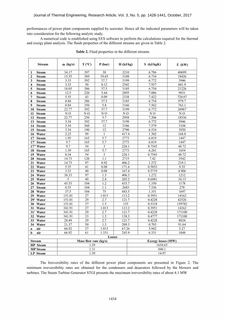
The minimum Exergy Destruction Rates are obtained for the condensers and deaerators followed by the blowers
and turbines. The Steam Turbine Generator STGI presents the maximum irreversibility rates of about 4.1 MW.
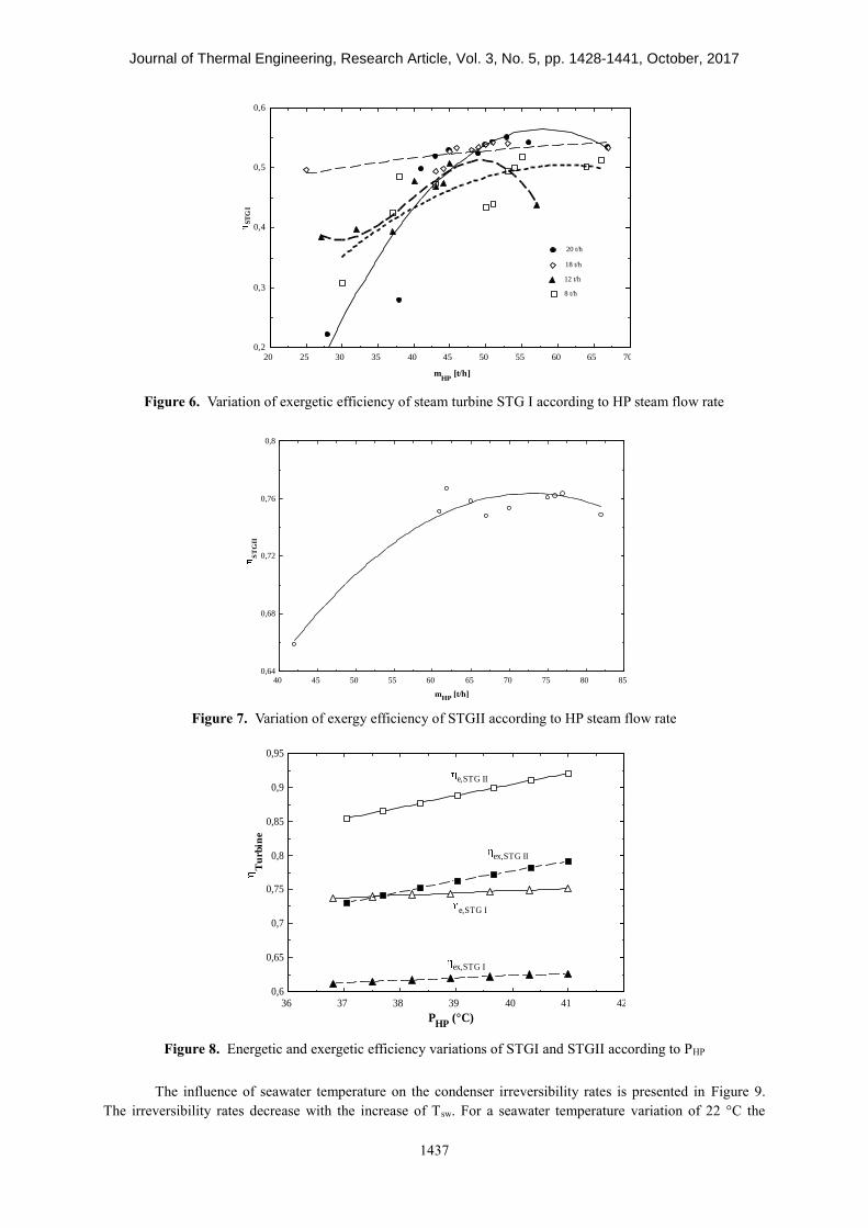
For the explored ranges of HP steam pressure, the energy efficiencies of steam turbine generators STGI and
STGII increase of about 1.37 % and 8.8 % respectively. While the exergy efficiencies increase of about 2.46 for
STGI and 6.8 % for STGII. In the same way optimum HP steam flow rate values, leading to the maximum
The Tunisian production of Phosphoric Acid is among the five important ones in the world. Indeed the
phosphate constitutes an important factor for the country economy balance. The annual production of Phosphoric
Acid is about 500 000 tonnes. Despite the economic importance of the phosphate industry, the total annual cost
of the energy production is very substantial. To overcome this problem, the Tunisian Chemical Group (TCG)
established programs in the purpose to improve the quality of production and increase the performance of the
different plants. Among these programs, a study is developed on the performance optimization of thermal power
plant operated in phosphoric acid factory. This study is conducted by the Applied Thermodynamic Research Unit
in collaboration with TCG.
Furthermore, several investigations were conducted on energy and exergy optimization of chemical
industrial factory power plants. S. Adibhatla et al. [1] carried out an energetic and exergetic analysis of 660 MWe
thermal power plant at different load conditions and according to two operating modes: under constant pressure
and under pure sliding pressure. The performance criteria are defined. Therefore, the exergy destruction rates are
identified for each component. In the developed analysis, it has been shown that the boiler has the highest source
of exergy losses followed by the turbine. Moreover, considering the two indicated operating modes, the results
reveal a significant decrease in exergy destruction rate for the turbine and boiler feed pump when operating in
sliding pressure mode.
CJ Koroneos et al. [2] conducted an exergy analysis of a 300 MW lignite thermoelectric power plant. A
comparative study is established between the actual plant and three proposed combined heat and power systems.
Equal amount of fuel is used for the three considered systems working according to Rankine cogeneration cycle.
Obtain results show that the cogeneration system design leads to an improvement at about 8.5% in energy
production compared to other proposed configurations.
A Thermodynamic and exergoeconomic analysis of thermal power plant is performed by A. Bolatturk et
al. [3]. Using EES software the inlet and outlet thermodynamic properties of each component are determined.
That permits to define energy and exergy efficiencies. Obtained results show that the main amounts of exergy
losses are located in the boiler, in the turbine, in the condenser, in the heater and in the pump groups. While the
Journal of Thermal Engineering, Research Article, Vol. 3, No. 5, pp. 1428-1441, October, 2017
1429
highest amount of exergy loss costs are observed in the boiler, followed by the turbines and the condenser.
Authors suggest that exergy and economic analysis of the thermal plants in project stage may be helpful to
undertake future investigations and can minimize significantly the energy consumption of thermal systems.
A. Atmaca. et al. [4] are developed a thermodynamic and exergoeconomic analysis of a cement plant
placed in Gaziantep, Turkey. The considered plant has highest energy consumption and it is classified among the
most industrial source of the CO2 emissions. In order to evaluate the performance of the factory, the authors are
established mass, thermal and exergy balances for each component considering variation ranges of operating
parameters. A set of performance criteria are defined in the aim to conduct this analysis.
A general methodology for exergy balance in chemical and thermal process integrated in the ProSimPlus code
was performed by A. Ghannadzadeh et al [5]. In the purpose to fully automate the exergy analysis, the authors
established an exergy balance for the whole system using only one software. The adopted procedure permits not
only to identify the exergy destruction source but it also to reduce the exergy losses.
M. N. Khan et al. [6] developed a thermodynamic optimization for a four configurations of a combined
steam and gas cycle with heat recovery steam generator. A parametric study is carried out in the purpose to
determine the effect of the pressure ratio and the inlet turbine temperature (TIT) on the cycle performance. The
results reveal that an increase in TIT leads to an increase in net output power of about 32.1% with 1500 K and
19.3 % with 2000 K.
An advanced energetic and exergetic analysis for a part of rubber factory has been conducted by G. D.
Vucovic et al. [7]. The main role of the considered part is the production of steam, compressed air as well as
cooling and hot water. Thermal and exergy balances are established for each components of the plant in order to
evaluate their performances. The exergy destructions are located for the different streams and their magnitude
are determined. That permits to evaluate the system exergy efficiency. Furthermore authors are divided the
exergy destructions rates into avoidable and unavoidable parts. The obtain results showed that reducing the
avoidable exergy destruction rates lead to an improvement in the exergy efficiency.
In order to determine the energy and exergy efficiency uncertainties of thermal power plant A. Ege et al.
[8] carried out an energy and exergy investigation for lignite thermal power plant at various load conditions. For
this reason, authors established a black box method by applying a sensitivity analysis in accordance with the
operating parameter variations. For the different power outputs, the results reveal a range varied between 1.82–
1.98% for energy efficiency uncertainty and 1.32–1.43% for exergy efficiency of the power plant. Moreover, the
Lower Heating Value (LHV) determination represents the highest source of uncertainties in energy and exergy
efficiency.
J. Taillon et al. [9] illustrate a graphical representation of energy efficiencies related to Combined Heat
and Power (CHP) and condensing plants. Basing exclusively on the energy efficiencies does not permit a
suitable comparison between the different energy system performances. Therefore authors conducted an exergy
analysis on 24 existing industrial factories and established two news graphs: the first one illustrates the electrical,
thermal and total exergy efficiencies of condensing and CHP power plants. The second graph splits the thermal
and exergy efficiency in two components: thermal losses and useful heat output quality.
A thermoeconomic optimization of a steam turbine power plant with a capacity of 450 MW is carried
out by L. Anetor et al. [10]. Exergy and economic balances are established for each component. All calculations
are performed using the sequential quadratic programming (SQP) algorithm. The main results show that the
outlet steam of the boiler has the minimum exergy cost while the highest one is assigned for the condenser.
Moreover, authors found that the pump inefficiencies cause an increase of the stream costs. Furthermore, the
optimization of the different plant equipment leads to an enhancement of the capital and operational cost while
only the capital cost was improved for the condenser optimization.
O. K. Singh et al. [11] conducted a numerical study on Kalina cycle coupled with steam power plant
stimulated by coal in order to valorize the exhaust gases at low temperature for electricity production. A model
is developed in the purpose to optimize the cycle performances according to the main operating parameters. An
optimum ammonia fraction value leading to the maximum cycle efficiency is obtained for a given turbine inlet
pressure. Therefore it has been demonstrated that the maximum cycle efficiency increases significantly with the
turbine inlet pressure. For turbine inlet pressure of 4000 kPa and an ammonia fraction of 0.8, an improvement of
0.277% and 0.255% in the overall energy and exergy efficiency respectively.
In order to define proper operating and maintenance decisions, T.K. Ray et al. [12] developed an exergy
analysis of a 500 MW steam power plant. The study is conducted considering design and off-design conditions
Journal of Thermal Engineering, Research Article, Vol. 3, No. 5, pp. 1428-1441, October, 2017
1430
for various values of superheat and reheats sprays. The obtain results constitute help tools for exergoeconomic
and maintenance optimization of similar power plants.
P. Regulagadda et al. [13] performed a thermodynamic analysis of a subcritical boiler-turbine generator
for a 32 MW coal-fired power plant. Energy and exergy equation governing the cycle are established. A
parametric study is conducted for a range of operating variables. That permits to define the optimum parameters
leading to the best plant performances. The boiler and turbine engender the maximum exergy destruction rates in
the power plant. The identification of the exergy losses in the different cycles has permitted to develop an
environmental impact and sustainability analysis.
A comparison between nine coal-fired power plants in Turkey is conducted by H. H. Erdem et al. [14].
For each plant a calculation model is proposed and the mass, energy and exergy balances are established. That
permits to determine the energy and exergy efficiency as well the exergy destruction rate of each component. A
comparison is then accomplished between the considered power plants. The obtained results may constitute
helpful tools for further investigations in the field of energetic and exergetic industrial power plant analysis.
F. Molés et al. [15] conducted a thermodynamic analysis of a combined organic Rankine cycle and
vapor compression cycle system using two different fluids with low Global Warming Potentials GWP for each
cycle. System performances are determined for ranges of operating conditions variations. Results show that the
combined cycle COP varied between 0.30 and 1.10 while the computed electrical COP is varied between 15 and
110. Furthermore, for vapor compression system the selection of working fluid does not affect significantly the
thermal and electrical efficiencies. Whereas for ORC the working fluid has an important influence especially on
the electrical efficiency.
F. Hajabdollahi et al. [16] established a soft computing based multi-objective optimization of steam
cycle power plant using Non-dominated Sorting Genetic Algorithm (NSGA-II) and Artificial Neural Network
(ANN). The main cycle parameter at the inlet and outlet of the different components are considered for the
optimization design. The maximization of the thermal efficiency and the minimization of the total cost rate are
taken as objective function is chosen in the purpose to optimize the running conditions of the power plant.
Obtain results reveal an increase of the thermal efficiency of about 3.76% and a decrease of the total cost rate of
about 3.84%.
A. Keçebaş [17] carried out a thermal, exergo-economic and environmental investigation of an existing
geothermal district heating systems installed in Afyon, Turkey. Based on data collected from the plant, authors
conduct an analysis in order to evaluate the heating system performance, the energy and exergy efficiencies, the
specific exergy index as well as the exergy destruction. Obtained results show an energy and exergy efficiencies
of the overall heating system of about 34.86% and 48.78%, respectively. Authors suggest that the main exergy
destruction rates are due to fluid reinjection, losses in heat exchangers and pipe lines, natural direct discharge and
the pump losses. Others advantages of the system are pointed out by authors such as positive effects on the
environment and low investment costs.
A. S. Karakurt et al. [18] carried out an analysis of steam turbine power plant performance under
different load and off design conditions. The effect of operating parameters on the steam turbine efficiency is
also studied. Obtained results showed that the design inlet high pressure turbine remains constant with variations
of load conditions. Whereas, the outlet pressure of different steam turbine technologies vary according to the
load. In other hand, the generated power is decreased with reducing the steam mass flow rate despite the
increasing of specific work.
R. Arora et al. [19] performed a study on the performance analysis of Brayton heat engine. The results
show that the engine designed at maximum efficient power criterion is more efficient compared with those
designed at maximum power and maximum power density conditions. The effect of the operating parameters on
the engine performances are analyzed.
N. Doseva et al. [20] conducted an energy and exergy analysis of cogeneration system with biogas
engines.
An exergetic and exergoeconomic analysis for solar thermal power plant is developed by A. M. Elsafi
[21]. Two steam power cycles are studied, with and without reheating system. Exergy and economic balances are
established for each component of the cycle. The obtained results show that the main sources of exergy
destruction are the solar field followed by the condenser, the LP turbine and the HP turbine. From thermo-
economic point of view and based on the total cost rate, the most expensive component is the solar field
followed by the LP turbine, HP turbine and the condenser. Authors analyzed the effect of steam reheat degree at
Journal of Thermal Engineering, Research Article, Vol. 3, No. 5, pp. 1428-1441, October, 2017
1431
the inlet of the LP turbine on the system performances. They observe that an increase in reheat degree of about
100 K leads to an increase of 9.1% in vapor fraction at the turbine outlet and a decrease of 1.5% in energetic and
exergetic efficiencies. Unfortunately an increase in electricity cost of about 2% is obtained.
S. Peng et al. [22] carried out an exergy investigation on solar hybrid coal fired power plant of 330 MW.
Solar system is used to heating feed water at temperature below 300 °C in the purpose to substitute the steam
extraction from steam turbine. That permits to improve the net electrical power generated by the steam turbine. A
thermal and economic comparison study is also established between solar-only and solar-hybrid coal-fired power
plants. According to the analysis results lower irreversibility rates are achieved in the solar feed water heater and
the steam turbine. An enhancement in exergy efficiency and solar energy conversion are obtained. Also the
hybrid coal-fired power plant seems to be economically beneficial than the solar-only thermal power plant.
M. H. K. Manesh et al. [23] developed an exergoeconomic and exergoenvironmental analysis on the
coupling of a gas fired steam power plant with a total site utility system. The main purpose of the study is to
analyze the incorporation of a steam power plant as an energy supply source for a site utility system. An
appropriate method is used to optimize the integration of a steam power plant and a site utility effect on the
whole plant performances. The obtain results show that this proposed design is a beneficial way leading to an
enhancement of energy and exergy efficiencies as well as good environmental impacts. Moreover this
integration leads to a decrease of the total annualized cost of the whole system compared with initial base design.
In this study, energy and exergy analysis is conducted on a Steam Turbine Power Plant installed in a
Phosphoric Acid factory in the purpose to define the optimum operating conditions. The main components of the
plant are presented. Mass, thermal and exergy balances are established. In order to perform all calculations
required for the exergetic analysis, a code is developed using EES software. The power plant performances are
analyzed taking into consideration variation ranges of the main operating parameters.
SYSTEM DESCRIPTION
The diagram of the Phosphoric Acid Thermal Power Plant is presented in Figure 1. This plant is
installed in the industrial area of the Tunisian Chemical Group (TCG) located in Gabes (South East - Tunisia).
The main product of this factory is the Phosphoric Acid with about 1500 t as daily production. The thermal
power plant of the indicated factory is mainly constituted by two steam turbine cycles STGI and STGII used to
provide about 14 MW as total net electrical power required for the different units. The High Pressure steam (HP)
mass flow rate, consumed by STGI and STGII is generated by an Evaporator Boiler Pre-superheater Superheater
group (EBPS) at about 40 bars and 410 °C. The steam turbine cycle STGI is with extraction and condensation,
while the second one STGII is with back pressure turbine.
Bl: Blower, CT: Condensate Tank, CTb:Turbo-blower Condenser, De: Deaerator, DU: Distillation Unit, EBPS: Evaporator_Boiler_Pre-superheater_Superheater,