ISSN 1330-3651 (Print), ISSN 1848-6339 (Online) https:doi.org/10.17559/TV-20160811162110 Original scientific paper Comparative and Exergetic Study of a Gas Turbine System with Inlet Air Cooling Mehmet DIREK, Mehmet Selçuk MERT Abstract: The efficiency of the combined cycle is significantly influenced by the temperature, pressure and humidity of the ambient air. The aim of this study is to investigate the influence of the inlet air cooling system (fogging cooling system) on the gas turbine performance by energy and exergy analyses. Energy and exergy analysis was carried out for nine cases based on the operation data of a gas turbine. Performance parameters include fuel consumption, specific fuel consumption, thermal efficiency, net power output, exergetic efficiency and exergy destruction rates of the components for the cases. It is concluded that the net power output of the gas-turbine system increases at lower inlet air temperatures, and based on the mean values, exergetic efficiency and exergy destruction ratio were found as 37.35% and 33.02%, respectively. Keywords: energy; exergy analysis; gas turbine; inlet air cooling; power generation 1 INTRODUCTION Some of the important parameters that influence the performance of the gas turbines are the ambient temperature, air pressure and moisture. As the temperature of air increases the density of air decreases, and the mass flow rate of compressed air diminishes. The power output of the gas turbine is proportional to the mass flow rate of air. As a remedy of this problem during hot seasons, the air at the compressor inlet is cooled. Various cooling methods are present for reducing the gas turbine inlet temperature. These methods are mainly evaporative coolers, spray inlet coolers or fogging systems, and mechanical refrigeration or chillers [1, 2]. Among these methods, fogging systems have become increasingly popular recently because of their effectiveness and low cost. The inlet air fogging systems, that inject water into the air flow passage through nozzles, causing the air to cool as the water droplets evaporates, are widely used. Cooling the inlet air to the wet bulb temperature will increase the density of the air and air mass flow, and hence will boost the power and efficiency of the plant. However, this type of cooling is limited by wet-bulb temperature. Engineers studied gas-turbine air intake systems in order to minimize the adverse effect of higher inlet air temperature on the turbine performance. There are various types of research in the literature related with inlet air cooling. Chaker et al. performed extensive experimental and theoretical studies, coupled with practical aspects learned in the design and implementation of nearly 500 inlet fogging systems on gas turbines ranging from 5 to 250 MW [3]. Utamura et al. determined that the power output of the gas turbine could be increased by 10% using 1% fogging under ambient conditions of 35°C and 53% relative humidity [4]. Bhargava et al. studied inlet air cooling effect on gas turbine performance by using fogging system and reported that high pressure inlet fogging could have had a different influencing effect on the performance of a combined cycle power plant [5]. An analytical method for evaluating the applicability of a combined cycle power plant with inlet air cooling was developed by Yang et al. They concluded that inlet fogging is superior in terms of power output at 15-20 °C ambient temperatures when compared with chilling [6]. El-Hadik performed a parametric study on the influence of ambient temperature, humidity and turbine inlet-temperature on power and thermal efficiency [7]. Unver et al. used degree day method to predict the theoretical maximum power production of gas turbine in different ambient temperatures. The influence of temperature drop on the power production was found to be 1.36 MW/°C [8]. In another study, a media evaporative cooling system installed in the gas turbines of the Iran combined cycle power plant is evaluated and the payback period is obtained about four years [9]. Sanaye and Tahani studied the effects of evaporative cooling on gas turbine performance. They proposed the prediction equations for the amount of actual increased net power output of various gas turbines [10]. The performance of energy systems is carried out on the basis of thermodynamic methods. Nevertheless, an energy analysis is not always enough to understand the performance of the energy systems while it only considers the amount of energy transferring through the system boundaries. Whereas, the exergy analysis is a practical method for evaluation of energy conversion processes and is regarded with the available part of the energy. Additionally, it enables to identify the location of irreversibilities and magnitudes of destructions [11, 12]. In recent years, exergy analysis of power and cooling system applications has attracted great interest. Khaliq and Dincer carried out the energetic and exergetic efficiencies of a gas turbine cogeneration plant with inlet air cooling. They concluded that system performance increased via using the cooling processes [13]. Athari et al. performed energy, exergy and exergoeconomic analyses of the integration of biomass gasification with a gas turbine plant incorporating fog cooling. Their results showed that increasing gas turbine inlet temperature improved the energy and exergy efficiencies [14]. In summer session energy efficiency of plant decreases by about 1.5% points without fog cooling system [15]. Barigozzi et al. reported on a techno-economical parametric analysis of an inlet air cooling system applied to an aero-derivative gas turbine for a combined cycle power plant. High temperature combined with low relative humidity sites typical of desert areas gives best techno-economic performance [16]. Ahmadi et al. performed thermodynamic modelling of a gas turbine cycle with absorption chiller. They determined that the cooling tower is calculated to have the highest exergy destruction rate with 3.16 MW [17]. Unver and Kilic conducted exergy analysis of a power plant considering environmental temperature variations. They found that 306 Technical Gazette 25, Suppl. 2(2018), 306-311
Transcript
ISSN 1330-3651 (Print), ISSN 1848-6339 (Online) https:doi.org/10.17559/TV-20160811162110 Original scientific paper
Comparative and Exergetic Study of a Gas Turbine System with Inlet Air Cooling
Mehmet DIREK, Mehmet Selçuk MERT
Abstract: The efficiency of the combined cycle is significantly influenced by the temperature, pressure and humidity of the ambient air. The aim of this study is to investigate the influence of the inlet air cooling system (fogging cooling system) on the gas turbine performance by energy and exergy analyses. Energy and exergy analysis was carried out for nine cases based on the operation data of a gas turbine. Performance parameters include fuel consumption, specific fuel consumption, thermal efficiency, net power output, exergetic efficiency and exergy destruction rates of the components for the cases. It is concluded that the net power output of the gas-turbine system increases at lower inlet air temperatures, and based on the mean values, exergetic efficiency and exergy destruction ratio were found as 37.35% and 33.02%, respectively.
Keywords: energy; exergy analysis; gas turbine; inlet air cooling; power generation
1 INTRODUCTION
Some of the important parameters that influence the performance of the gas turbines are the ambient temperature, air pressure and moisture. As the temperature of air increases the density of air decreases, and the mass flow rate of compressed air diminishes. The power output of the gas turbine is proportional to the mass flow rate of air. As a remedy of this problem during hot seasons, the air at the compressor inlet is cooled. Various cooling methods are present for reducing the gas turbine inlet temperature. These methods are mainly evaporative coolers, spray inlet coolers or fogging systems, and mechanical refrigeration or chillers [1, 2]. Among these methods, fogging systems have become increasingly popular recently because of their effectiveness and low cost.
The inlet air fogging systems, that inject water into the air flow passage through nozzles, causing the air to cool as the water droplets evaporates, are widely used. Cooling the inlet air to the wet bulb temperature will increase the density of the air and air mass flow, and hence will boost the power and efficiency of the plant. However, this type of cooling is limited by wet-bulb temperature.
Engineers studied gas-turbine air intake systems in order to minimize the adverse effect of higher inlet air temperature on the turbine performance. There are various types of research in the literature related with inlet air cooling. Chaker et al. performed extensive experimental and theoretical studies, coupled with practical aspects learned in the design and implementation of nearly 500 inlet fogging systems on gas turbines ranging from 5 to 250 MW [3]. Utamura et al. determined that the power output of the gas turbine could be increased by 10% using 1% fogging under ambient conditions of 35°C and 53% relative humidity [4]. Bhargava et al. studied inlet air cooling effect on gas turbine performance by using fogging system and reported that high pressure inlet fogging could have had a different influencing effect on the performance of a combined cycle power plant [5]. An analytical method for evaluating the applicability of a combined cycle power plant with inlet air cooling was developed by Yang et al. They concluded that inlet fogging is superior in terms of power output at 15-20 °C ambient temperatures when compared with chilling [6]. El-Hadik performed a parametric study on the influence of ambient temperature, humidity and turbine inlet-temperature on power and
thermal efficiency [7]. Unver et al. used degree day method to predict the theoretical maximum power production of gas turbine in different ambient temperatures. The influence of temperature drop on the power production was found to be 1.36 MW/°C [8]. In another study, a media evaporative cooling system installed in the gas turbines of the Iran combined cycle power plant is evaluated and the payback period is obtained about four years [9]. Sanaye and Tahani studied the effects of evaporative cooling on gas turbine performance. They proposed the prediction equations for the amount of actual increased net power output of various gas turbines [10].
The performance of energy systems is carried out on the basis of thermodynamic methods. Nevertheless, an energy analysis is not always enough to understand the performance of the energy systems while it only considers the amount of energy transferring through the system boundaries. Whereas, the exergy analysis is a practical method for evaluation of energy conversion processes and is regarded with the available part of the energy. Additionally, it enables to identify the location of irreversibilities and magnitudes of destructions [11, 12].
In recent years, exergy analysis of power and cooling system applications has attracted great interest. Khaliq and Dincer carried out the energetic and exergetic efficiencies of a gas turbine cogeneration plant with inlet air cooling. They concluded that system performance increased via using the cooling processes [13]. Athari et al. performed energy, exergy and exergoeconomic analyses of the integration of biomass gasification with a gas turbine plant incorporating fog cooling. Their results showed that increasing gas turbine inlet temperature improved the energy and exergy efficiencies [14]. In summer session energy efficiency of plant decreases by about 1.5% points without fog cooling system [15]. Barigozzi et al. reported on a techno-economical parametric analysis of an inlet air cooling system applied to an aero-derivative gas turbine for a combined cycle power plant. High temperature combined with low relative humidity sites typical of desert areas gives best techno-economic performance [16]. Ahmadi et al. performed thermodynamic modelling of a gas turbine cycle with absorption chiller. They determined that the cooling tower is calculated to have the highest exergy destruction rate with 3.16 MW [17]. Unver and Kilic conducted exergy analysis of a power plant considering environmental temperature variations. They found that
306 Technical Gazette 25, Suppl. 2(2018), 306-311
Mehmet DIREK, Mehmet Selçuk MERT: Comparative and Exergetic Study of a Gas Turbine System with Inlet Air Cooling
Tehnički vjesnik 25, Suppl. 2(2018), 306-311 307
specific fuel consumption reduced by 5% when the environmental temperature decreases [18]. Najjaret al. found that thermal efficiency and exergy efficiency of a gas turbine was 30.38% and 37.23%, respectively at 45 °C ambient temperature conditions [19]. Ehyaei et al. have done a comprehensive thermodynamic modelling of a combined cycle power plant considering the effects of inlet fogging by using exergy method and found that the utilization of the fog air cooling systems can improve the plant efficiency in hot and dry regions [20].
In this study, a comparative and exergetic study of a gas turbine system with inlet air cooling based on actual operating data belonging to 239 MW power plant, was done. The influence of fogging system on the net power output was determined. Fuel consumption, specific fuel consumption, thermal efficiency, net power output of the system, exergy efficiency and exergy destruction rates of the plant were obtained.
2 GAS TURBINE SYSTEM
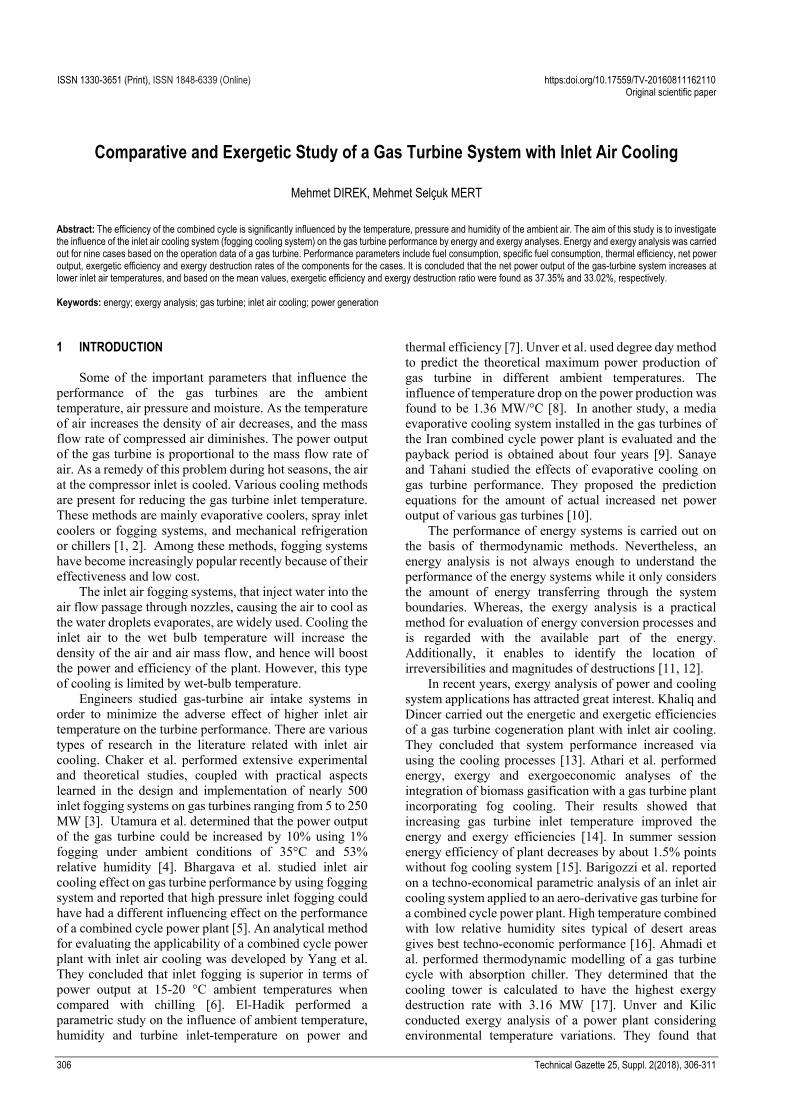
The investigated plant is a part of a combined cycle power plant, which is located in Marmara Region (Turkey). The nominal power output of the gas turbine is 239 MW at ISO conditions (15 °C and 60% RH). The mass flow rate of the air at the compressor is 649 kg/s, and the pressure ratio is 16 bar (Fig. 1).
Figure 1 Block flow diagram of the gas turbine
The cooling effect is provided by water evaporation before air enters into the compressor. By using nozzles, demineralized water is converted into a fog. In the fogging system, water evaporation is achieved prior to the air entering into the compressor. However, evaporative cooling has some limitations based on the ambient humidity conditions.
3 ENERGY AND EXERGY ANALYSIS
Thermodynamic changes can take place between the air and the water in a fogging system. The first laws of thermodynamics are employed to investigate the performance of inlet fogging system.
Under the assumption of ideal gas behaviour, the humidity ratio (ω) can be described as follows:
)/()622.0( vv PPP −=ω (1) The energy balance equation for fogging system is,
wiaeaiaea hhh )( ,,,, ωω −+= (2)
Some assumptions have been done during the analysis of the system. All processes in the cases were assumed as
steady-state. Kinetic and potential energy effects were neglected. The air and natural gas were considered ideal gases. The gain and loss of heat, pressure drops, have been neglected, and all equipment operates adiabatically. The mass flow rate in the air compressor was 649 kg/s in all cases. Environmental conditions were taken as the reference state for each case.
The rate of total exergy destruction for a control volume at steady state condition equation is given below.
L DQ i x e x Wi ei e
Ex m e m e Ex Ex Ex+ = + + +∑ ∑
(3)
The exergy content of a heat transfer rate and work are,
01Q ii
TEx Q
T
= −
(4)
WxE W = (5)
Kinetic and potential exergy are assumed to be negligible and the total exergy of the system can be calculated by:
ph chx x xe e e= + (6)
Physical exergy can be calculated by:
ph0 0 0( ) ( )xe h h T s s= − − − (7)
Chemical exergy can be found as follows:
ch ch0mix
1 1ln
n n
x i x i iii i
e y e RT y y= =
= +∑ ∑ (8)
For the kth component of a system, the exergy balance can be formulated as [21, 22]:
F, P, L, D,k k k kEx Ex Ex Ex= + + (9)
Here the F, P, L, and D indices are for fuel, product, loss and destruction, respectively. The exergy of fuel is the exergy entering the system and the exergy of product is the exergy of existing stream or work. Exergy loss is the thermodynamic loss caused by the exergy transfer to the environment. Exergy destruction is the loss due to the irreversibilities within the system boundaries [21, 22].
The exergetic efficiency (ε) and the improvement potential ( potI ) can be formulated as [21]:
P, F, D, F,/ 1 ( / )k k k kEx Ex Ex Exε = = − (10)
pot D, L,(1 )k kI Ex Exε= − + (11)
The exergy destruction ratio ( D, ky ) is the ratio of the
exergy destruction ( D, kEx ) in the kth component to the
fuel supplied to the overall system ( F, totEx ) [21]:
Mehmet DIREK, Mehmet Selçuk MERT: Comparative and Exergetic Study of a Gas Turbine System with Inlet Air Cooling
308 Technical Gazette 25, Suppl. 2(2018), 306-311
D, D,
F, tot
kk
Exy
Ex=
(12)
While the specific fuel consumption can be calculated from the following equation:
net
3600mSFCW
=
(13)
4 RESULTS AND DISCUSSION
The performance of the gas-turbine was investigated to obtain the influence of the fogging system by using the recorded values from the power plant. Calculations were carried out considering different inlet temperatures. For this aim, nine distinct cases were determined (Tab. 1).
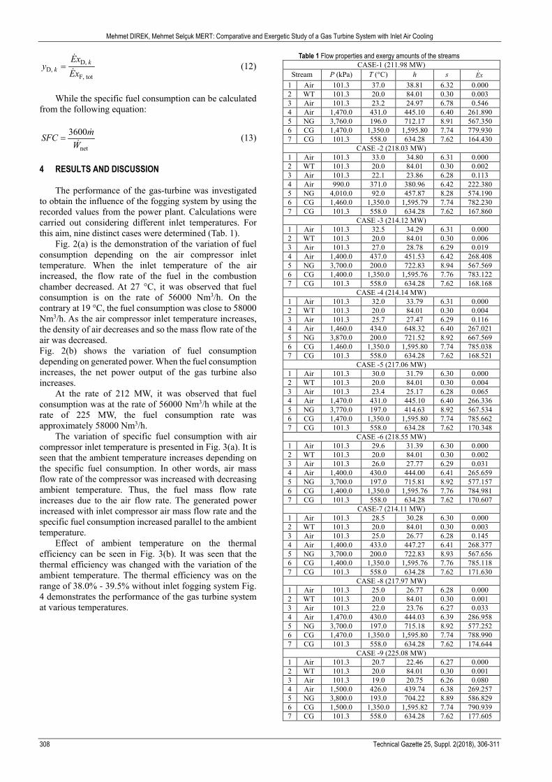
Fig. 2(a) is the demonstration of the variation of fuel consumption depending on the air compressor inlet temperature. When the inlet temperature of the air increased, the flow rate of the fuel in the combustion chamber decreased. At 27 °C, it was observed that fuel consumption is on the rate of 56000 Nm3/h. On the contrary at 19 °C, the fuel consumption was close to 58000 Nm3/h. As the air compressor inlet temperature increases, the density of air decreases and so the mass flow rate of the air was decreased. Fig. 2(b) shows the variation of fuel consumption depending on generated power. When the fuel consumption increases, the net power output of the gas turbine also increases.
At the rate of 212 MW, it was observed that fuel consumption was at the rate of 56000 Nm3/h while at the rate of 225 MW, the fuel consumption rate was approximately 58000 Nm3/h.
The variation of specific fuel consumption with air compressor inlet temperature is presented in Fig. 3(a). It is seen that the ambient temperature increases depending on the specific fuel consumption. In other words, air mass flow rate of the compressor was increased with decreasing ambient temperature. Thus, the fuel mass flow rate increases due to the air flow rate. The generated power increased with inlet compressor air mass flow rate and the specific fuel consumption increased parallel to the ambient temperature.
Effect of ambient temperature on the thermal efficiency can be seen in Fig. 3(b). It was seen that the thermal efficiency was changed with the variation of the ambient temperature. The thermal efficiency was on the range of 38.0% - 39.5% without inlet fogging system Fig. 4 demonstrates the performance of the gas turbine system at various temperatures.
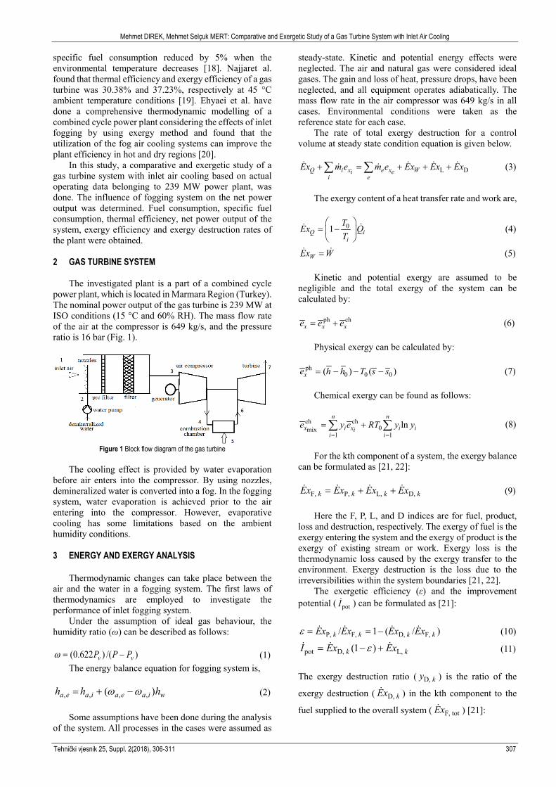
Table 1 Flow properties and exergy amounts of the streams CASE-1 (211.98 MW)
Mehmet DIREK, Mehmet Selçuk MERT: Comparative and Exergetic Study of a Gas Turbine System with Inlet Air Cooling
Tehnički vjesnik 25, Suppl. 2(2018), 306-311 309
Figure 2 (a) Variation of power consumption depending on air compressor inlet temperature
(b) Variation of fuel consumption depending on generated power
Figure 3 (a) Variation of specific fuel Consumption depending on compressor inlet temperature
(b) Variation of thermal efficiency depending on ambient temperature
Figure 4 Variation of turbine net power output depending on ambient
temperature
Based on the results, when the inlet temperature of the air increased, it caused a decrease in flow rate of the fuel.
Thus, the generated power of the gas turbine was also decreased. The net generated power from the plant was decreased in contrast with increased temperature. Conversely, the power and efficiency increased when the inlet air temperature was reduced.
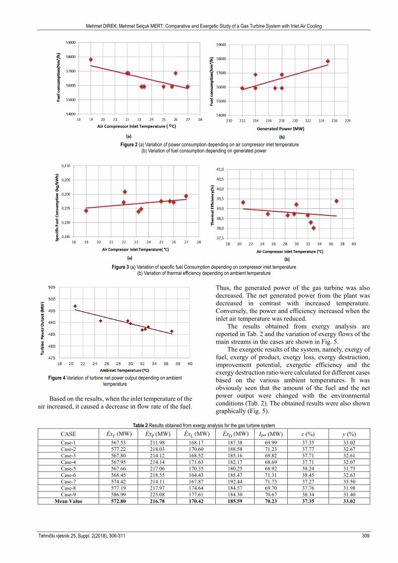
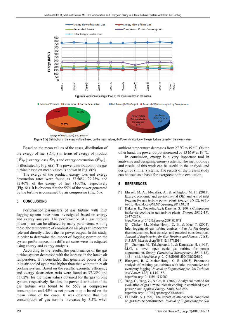
The results obtained from exergy analysis are reported in Tab. 2 and the variation of exergy flows of the main streams in the cases are shown in Fig. 5.
The exergetic results of the system, namely, exergy of fuel, exergy of product, exergy loss, exergy destruction, improvement potential, exergetic efficiency and the exergy destruction ratio were calculated for different cases based on the various ambient temperatures. It was obviously seen that the amount of the fuel and the net power output were changed with the environmental conditions (Tab. 2). The obtained results were also shown graphically (Fig. 5).
Table 2 Results obtained from exergy analysis for the gas turbine system
Mean Value 572.80 216.78 170.42 185.59 70.23 37.35 33.02
Mehmet DIREK, Mehmet Selçuk MERT: Comparative and Exergetic Study of a Gas Turbine System with Inlet Air Cooling
310 Technical Gazette 25, Suppl. 2(2018), 306-311
Figure 5 Variation of exergy flows of the main streams in the cases
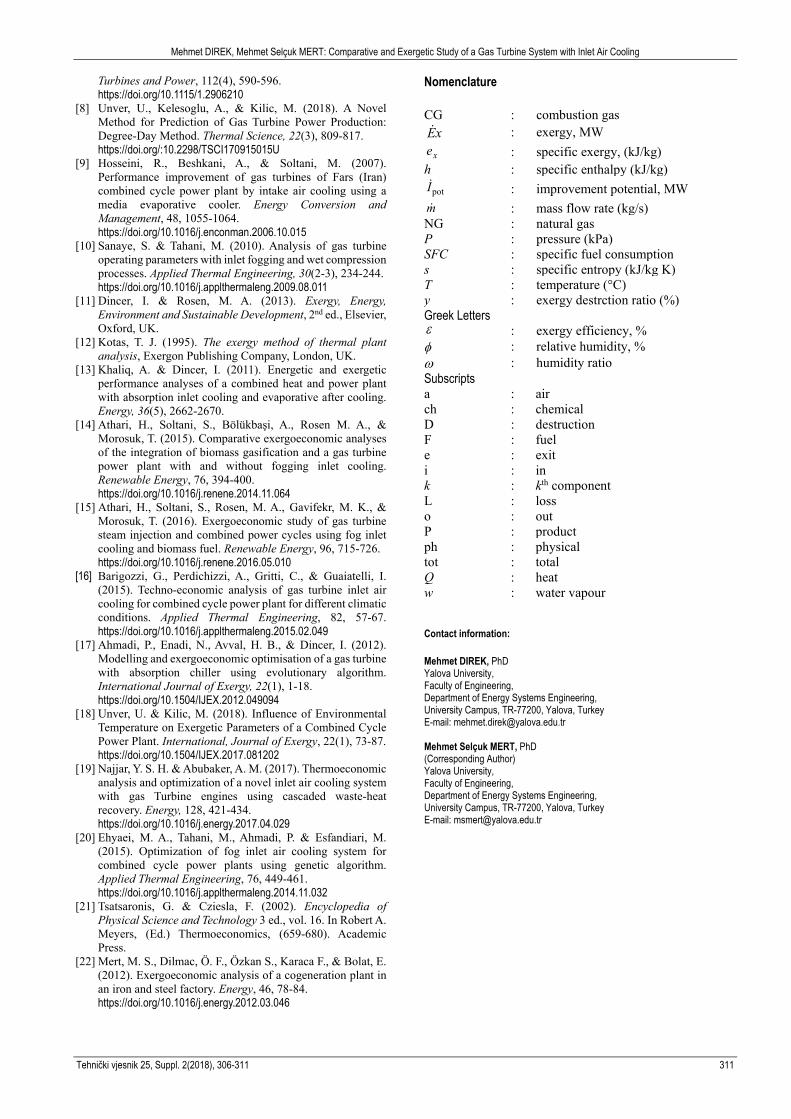
Figure 6 (a) Distribution of the exergy of fuel based on the mean values, (b) Power distribution of the gas turbine based on the mean values
Based on the mean values of the cases, distribution of
the exergy of fuel ( FEx ) in terms of exergy of product
( PEx ), exergy loss ( LEx ) and exergy destruction D( ),Ex is illustrated by Fig. 6(a). The power distribution of the gas turbine based on mean values is shown in Fig. 6(b).
The exergy of the product, exergy loss and exergy destruction rates were found as 37.50%, 29.75% and 32.40%, of the exergy of fuel (100%), respectively (Fig. 6a). It is obvious that the 55% of the power generated by the turbine is consumed by air compressor (Fig. 6b).
5 CONCLUSIONS
Performance parameters of gas turbine with inlet fogging system have been investigated based on energy and exergy analysis. The performance of a gas turbine power plant can be affected by many parameters. Among these, the temperature of combustion air plays an important role and directly affects the net power output. In this study, in order to determine the impact of fogging system on the system performance, nine different cases were investigated using energy and exergy analysis.
According to the results, the performance of the gas turbine system decreased with the increase in the intake air temperature. It is concluded that generated power of the inlet air-cooled cycle was higher than that without inlet air cooling system. Based on the results, exergetic efficiency and exergy destruction ratio were found as 37.35% and 33.02%, for the mean values obtained for the gas turbine system, respectively. Besides, the power distribution of the gas turbine was found to be 55% as compressor consumption and 45% as net power output based on the mean value of the cases. It was observed that fuel consumption of gas turbine increases by 3.5% when
ambient temperature decreases from 27 °C to 19 °C. On the other hand, the power output increased by 13 MW at 19 °C.
In conclusion, exergy is a very important tool in analysing and designing energy systems. The methodology and results of this work can be useful in the analysis and design of similar systems. The results of the present study can be used as a basis for exergoeconomic evaluation.
6 REFERENCES
[1] Ehyaei, M. A., Mozafari, A., & Alibiglou, M. H. (2011).
Exergy, economic and environmental (3E) analysis of inlet fogging for gas turbine power plant. Energy, 36(12), 6851-6861. https://doi.org/10.1016/j.energy.2011.10.011
[2] Kakaras, E., Doukelis, A., & Karellas, S. (2004). Compressor intake-air cooling in gas turbine plants. Energy, 29(12-15), 2347-2358. https://doi.org/10.1016/j.energy.2004.03.043 [3] Chaker, M., Meher-Homji, C. B., & Mee, T. (2004). Inlet fogging of gas turbine engines - Part A: fog droplet thermodynamics, heat transfer, and practical considerations. Journal of Engineering for Gas Turbines and Power, 126(3), 545-558. https://doi.org/10.1115/1.1712981 [4] Utamura, M., Takeharaand, I., & Karasawa, H. (1998). MAT, a novel, open cycle gas turbine for power augmentation. Energy Conversion Management, 39(16-18), 1631-1642. https://doi.org/10.1016/S0196-8904(98)00088-0
[5] Bhargava, R. & Meher-Homji, C. B. (2005). Parametric analysis of existing gas turbines with inlet evaporative and overspray fogging. Journal of Engineering for Gas Turbines and Power, 127(1), 145-158. https://doi.org/10.1115/1.1712980
[6] Yang, C., Yang, Z., & Cai, R. (2009). Analytical method for evaluation of gas turbine inlet air cooling in combined cycle power plant. Applied Energy, 86(6), 848-856. https://doi.org/10.1016/j.apenergy.2008.08.019
[7] El Hadik, A. (1990). The impact of atmospheric conditions on gas turbine performance. Journal of Engineering for Gas
Mehmet DIREK, Mehmet Selçuk MERT: Comparative and Exergetic Study of a Gas Turbine System with Inlet Air Cooling
Tehnički vjesnik 25, Suppl. 2(2018), 306-311 311
Turbines and Power, 112(4), 590-596. https://doi.org/10.1115/1.2906210
[8] Unver, U., Kelesoglu, A., & Kilic, M. (2018). A Novel Method for Prediction of Gas Turbine Power Production: Degree-Day Method. Thermal Science, 22(3), 809-817. https://doi.org/:10.2298/TSCI170915015U
[9] Hosseini, R., Beshkani, A., & Soltani, M. (2007). Performance improvement of gas turbines of Fars (Iran) combined cycle power plant by intake air cooling using a media evaporative cooler. Energy Conversion and Management, 48, 1055-1064. https://doi.org/10.1016/j.enconman.2006.10.015
[10] Sanaye, S. & Tahani, M. (2010). Analysis of gas turbine operating parameters with inlet fogging and wet compression processes. Applied Thermal Engineering, 30(2-3), 234-244. https://doi.org/10.1016/j.applthermaleng.2009.08.011
[11] Dincer, I. & Rosen, M. A. (2013). Exergy, Energy, Environment and Sustainable Development, 2nd ed., Elsevier, Oxford, UK.
[12] Kotas, T. J. (1995). The exergy method of thermal plant analysis, Exergon Publishing Company, London, UK.
[13] Khaliq, A. & Dincer, I. (2011). Energetic and exergetic performance analyses of a combined heat and power plant with absorption inlet cooling and evaporative after cooling. Energy, 36(5), 2662-2670.
[14] Athari, H., Soltani, S., Bölükbaşi, A., Rosen M. A., & Morosuk, T. (2015). Comparative exergoeconomic analyses of the integration of biomass gasification and a gas turbine power plant with and without fogging inlet cooling. Renewable Energy, 76, 394-400. https://doi.org/10.1016/j.renene.2014.11.064
[15] Athari, H., Soltani, S., Rosen, M. A., Gavifekr, M. K., & Morosuk, T. (2016). Exergoeconomic study of gas turbine steam injection and combined power cycles using fog inlet cooling and biomass fuel. Renewable Energy, 96, 715-726. https://doi.org/10.1016/j.renene.2016.05.010
[16] Barigozzi, G., Perdichizzi, A., Gritti, C., & Guaiatelli, I. (2015). Techno-economic analysis of gas turbine inlet air cooling for combined cycle power plant for different climatic conditions. Applied Thermal Engineering, 82, 57-67. https://doi.org/10.1016/j.applthermaleng.2015.02.049
[17] Ahmadi, P., Enadi, N., Avval, H. B., & Dincer, I. (2012). Modelling and exergoeconomic optimisation of a gas turbine with absorption chiller using evolutionary algorithm. International Journal of Exergy, 22(1), 1-18. https://doi.org/10.1504/IJEX.2012.049094
[18] Unver, U. & Kilic, M. (2018). Influence of Environmental Temperature on Exergetic Parameters of a Combined Cycle Power Plant. International, Journal of Exergy, 22(1), 73-87. https://doi.org/10.1504/IJEX.2017.081202
[19] Najjar, Y. S. H. & Abubaker, A. M. (2017). Thermoeconomic analysis and optimization of a novel inlet air cooling system with gas Turbine engines using cascaded waste-heat recovery. Energy, 128, 421-434. https://doi.org/10.1016/j.energy.2017.04.029
[20] Ehyaei, M. A., Tahani, M., Ahmadi, P. & Esfandiari, M. (2015). Optimization of fog inlet air cooling system for combined cycle power plants using genetic algorithm. Applied Thermal Engineering, 76, 449-461. https://doi.org/10.1016/j.applthermaleng.2014.11.032
[21] Tsatsaronis, G. & Cziesla, F. (2002). Encyclopedia of Physical Science and Technology 3 ed., vol. 16. In Robert A. Meyers, (Ed.) Thermoeconomics, (659-680). Academic Press.
[22] Mert, M. S., Dilmac, Ö. F., Özkan S., Karaca F., & Bolat, E. (2012). Exergoeconomic analysis of a cogeneration plant in an iron and steel factory. Energy, 46, 78-84. https://doi.org/10.1016/j.energy.2012.03.046
Nomenclature CG : combustion gas Ex : exergy, MW
xe : specific exergy, (kJ/kg) h : specific enthalpy (kJ/kg)
potI : improvement potential, MW m : mass flow rate (kg/s) NG : natural gas P : pressure (kPa) SFC : specific fuel consumption s : specific entropy (kJ/kg K) T : temperature (°C) y : exergy destrction ratio (%) Greek Letters ε : exergy efficiency, % φ : relative humidity, % ω : humidity ratio Subscripts a : air ch : chemical D : destruction F : fuel e : exit i : in k : kth component L : loss o : out P : product ph : physical tot : total Q : heat w : water vapour Contact information: Mehmet DIREK, PhD Yalova University, Faculty of Engineering, Department of Energy Systems Engineering, University Campus, TR-77200, Yalova, Turkey E-mail: [email protected] Mehmet Selçuk MERT, PhD (Corresponding Author) Yalova University, Faculty of Engineering, Department of Energy Systems Engineering, University Campus, TR-77200, Yalova, Turkey E-mail: [email protected]