Potential of a Chemical Heat Storage as a Heat for a Catalytic Converter
Measures that heat up exhaust aftertreatment systems fast lead in general to lower fuel economy. A chemical heat storage (CHS) represents a new concept to exceed light-off temperatures fast. As a part of an FVV research project, potential storage materials were researched and analysed at Leuphana University Lüneburg. Their potential was then examined at the TU Braunschweig and prototype tests were carried out.
AUTHORS
Michael Albrechtis Research Assistant at the Institute of Internal Combustion Engines at
TU Braunschweig (Germany).
Kevin Frieseis Research Assistant at the Institute of Internal Combustion Engines at
TU Braunschweig (Germany).
Holger Rammelbergis Research Assistant at the Faculty Sustainable
In order efficiently reduce the polluting emissions of engines by exhaust aftertreatment systems, the temperatures of the catalytic converters should be above their light-off temperatures. Methods in the thermal management, which are used to heat up the cata-lytic converters or keep them above their light-off temperature result in an increased fuel consumption. By the use of a chemical heat storage (CHS), which is integrated into the exhaust pipe upstream of the exhaust aftertreatment system, this extra con-sumption might be reduced.
The CHS is a heat exchanger, which is flowed through by the exhaust gas on one side and is filled up with a thermochemical stor-age material (TCM) on the other side. When a mobile phase is added, the TCM releases thermal energy by an exothermic reaction which heats up the exhaust gas upstream of the exhaust aftertreat-
ment – this represents the discharging process. Caused by a heat input into the TCM – the charging process – the mobile phase is separated from the TCM in an endothermic reaction and is stored separately in a closed system to be available for heat release by dis-charging when needed.
The working principle of the CHS and the integration into the exhaust gas flow is shown in FIGURE 1. Especially the high energy and power density compared to a sensible or latent heat storages, as well as the possibility of storing heat without any losses indefi-nitely, are the advantages of a TCM. The control of the water input allows the regulation of the heat release rate.
During the project, a research about possible TCM and a poten-tial analysis were carried out simultaneously. Subsequently, an upscaling of the samples was performed in the lab, so a prototype could be built and tested at the end of the project.
2 MATERIAL DETERMINATION
A systematic literature research of the materials was performed in terms of safety, heat storage capacity, equilibrium temperature and reversibility. The heat storage capacity of a CHS should at least be 270 kJ/kg. This matches with the estimated energy stor-age density of an electric catalytic converter heating solution including an electric battery. The temperature range of the reac-tion equilibrium should be between 400 and 500 °C for a gasoline engine and between 250 and 350 °C for a diesel engine.
Of the initial 132 materials, only 39 compounds fulfil the obliga-tory thermal stability. Because of the manageability, safety and the high realisation potential of water, another 13 substances were dis-carded due to their reaction partners (carbon dioxide, hydrogen and oxygen) as reaction partners (reactant) in the reaction equilibrium. Of the remaining materials, only six fulfil the criteria of a reaction temperature between 250 and 600 °C, TABLE 1. With the help of a thermogravimetric and microcalorimetric (TGA/DSC) screening on the milligram scale, the heat storage capacity, reversibility, cycle stability as well as the heat release were measured. Of the priori-tised materials, only the reaction pair of calcium oxide and calcium hydroxide met all the criteria per the chemical equation:
7 COMPARISON OF THE MEASUREMENTS WITH THE SIMULATION MODEL
8 SUMMARY AND OUTLOOK
MTZ worldwide 05|2017 73
Eq. 1 CaO+H 2O→Ca(OH)2+ΔH (ΔH=1400 kJ/ kg)
In particular, the reversibility with over 600 storage cycles could be shown after which experiments on a bigger scale were planned, FIGURE 2.
3 POTENTIAL ANALYSIS
After the start of the project, the potential of a chemical heat stor-age was analysed simultaneously to the material selection. The analysis was carried out using a 0-D/1-D model. Three different kinds of heat exchangers were investigated and the results showed the best performance when tube bundle heat exchangers were used. Simulations were based on the calculation of the energy flows: the heat fluxes to the environment, to the adjacent parts of the exhaust system and inside the CHS were taken into consider-ation. The kinetics of the chemical reaction was estimated by the project partner, so an estimated heat release rate could be spec-ified in the model.
In the potential analysis, three different applications of a TWC were investigated: a conventional vehicle, a hybrid vehicle and a CHP unit. Furthermore, the heat up and regeneration of NSC and SCR systems were studied. Major differences in these cases are the exhaust gas temperature, which is important for the TCM charging process, and the light-off temperatures of the converters. That is why different TCM were considered. Basic properties, like energy density or mass density, were known at this state of the project. In the course of the material determination in Lüneburg, it turned out that the available TCM for lower temperature ranges (NSC, SCR) had too slow reaction kinetics for the application; hence it was no longer considered in the further course of the pro-ject. Of the tree applications of a TWC, mentioned above, for which calcium oxide was determined as the TCM, the case of the hybrid vehicle turned out as the most applicable case. Hence, this case was chosen for the design of the prototype. The thermal inertia of the CHS was too high for the application of the conventional vehi-cle, which means that the TWC could not be heated up in the nec-essary period of time. In the case of the CHP unit, due to the cur-rent legislation, there is no need to integrate a CHS, which is why this application was no longer considered. The potential analysis
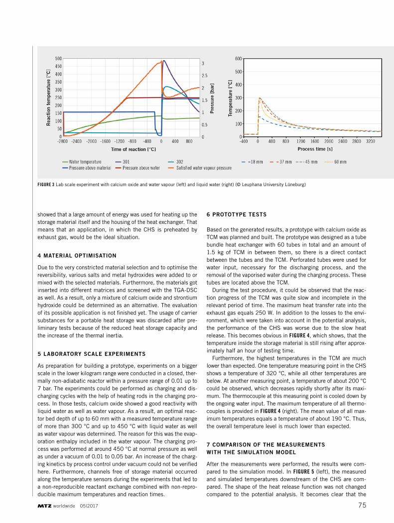
showed that a large amount of energy was used for heating up the storage material itself and the housing of the heat exchanger. That means that an application, in which the CHS is preheated by exhaust gas, would be the ideal situation.
4 MATERIAL OPTIMISATION
Due to the very constricted material selection and to optimise the reversibility, various salts and metal hydroxides were added to or mixed with the selected materials. Furthermore, the materials got inserted into different matrices and screened with the TGA-DSC as well. As a result, only a mixture of calcium oxide and strontium hydroxide could be determined as an alternative. The evaluation of its possible application is not finished yet. The usage of carrier substances for a portable heat storage was discarded after pre-liminary tests because of the reduced heat storage capacity and the increase of the thermal inertia.
5 LABORATORY SCALE EXPERIMENTS
As preparation for building a prototype, experiments on a bigger scale in the lower kilogram range were conducted in a closed, ther-mally non-adiabatic reactor within a pressure range of 0.01 up to 7 bar. The experiments could be performed as charging and dis-charging cycles with the help of heating rods in the charging pro-cess. In those tests, calcium oxide showed a good reactivity with liquid water as well as water vapour. As a result, an optimal reac-tor bed depth of up to 60 mm with a measured temperature range of more than 300 °C and up to 450 °C with liquid water as well as water vapour was determined. The reason for this was the evap-oration enthalpy included in the water vapour. The charging pro-cess was performed at around 450 °C at normal pressure as well as under a vacuum of 0.01 to 0.05 bar. An increase of the charg-ing kinetics by process control under vacuum could not be verified here. Furthermore, channels free of storage material occurred along the temperature sensors during the experiments that led to a non-reproducible reactant exchange combined with non-repro-ducible maximum temperatures and reaction times.
6 PROTOTYPE TESTS
Based on the generated results, a prototype with calcium oxide as TCM was planned and built. The prototype was designed as a tube bundle heat exchanger with 60 tubes in total and an amount of 1.5 kg of TCM in between them, so there is a direct contact between the tubes and the TCM. Perforated tubes were used for water input, necessary for the discharging process, and the removal of the vaporised water during the charging process. These tubes are located above the TCM.
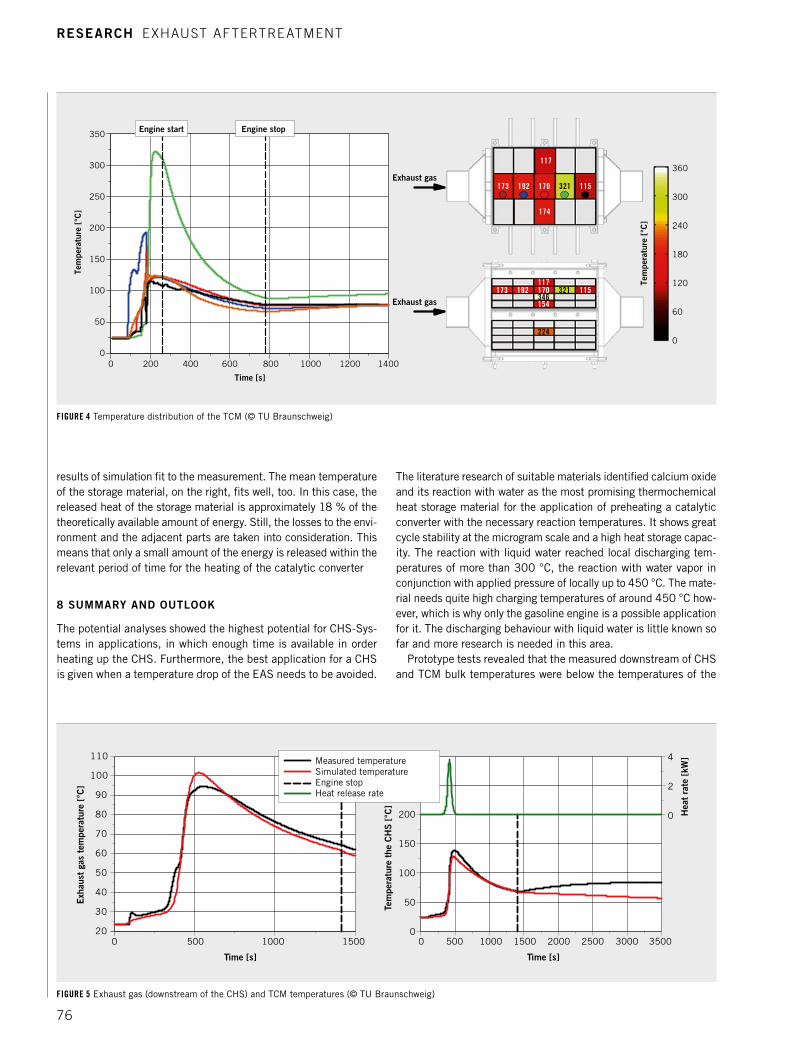
During the test procedure, it could be observed that the reac-tion progress of the TCM was quite slow and incomplete in the relevant period of time. The maximum heat transfer rate into the exhaust gas equals 250 W. In addition to the losses to the envi-ronment, which were taken into account in the potential analysis, the performance of the CHS was worse due to the slow heat release. This becomes obvious in FIGURE 4, which shows, that the temperature inside the storage material is still rising after approx-imately half an hour of testing time.
Furthermore, the highest temperatures in the TCM are much lower than expected. One temperature measuring point in the CHS shows a temperature of 320 °C, while all other temperatures are below. At another measuring point, a temperature of about 200 °C could be observed, which decreases rapidly shortly after its maxi-mum. The thermocouple at this measuring point is cooled down by the ongoing water input. The maximum temperature of all thermo-couples is provided in FIGURE 4 (right). The mean value of all max-imum temperatures equals a temperature of about 190 °C. Thus, the overall temperature level is much lower than expected.
7 COMPARISON OF THE MEASUREMENTS WITH THE SIMULATION MODEL
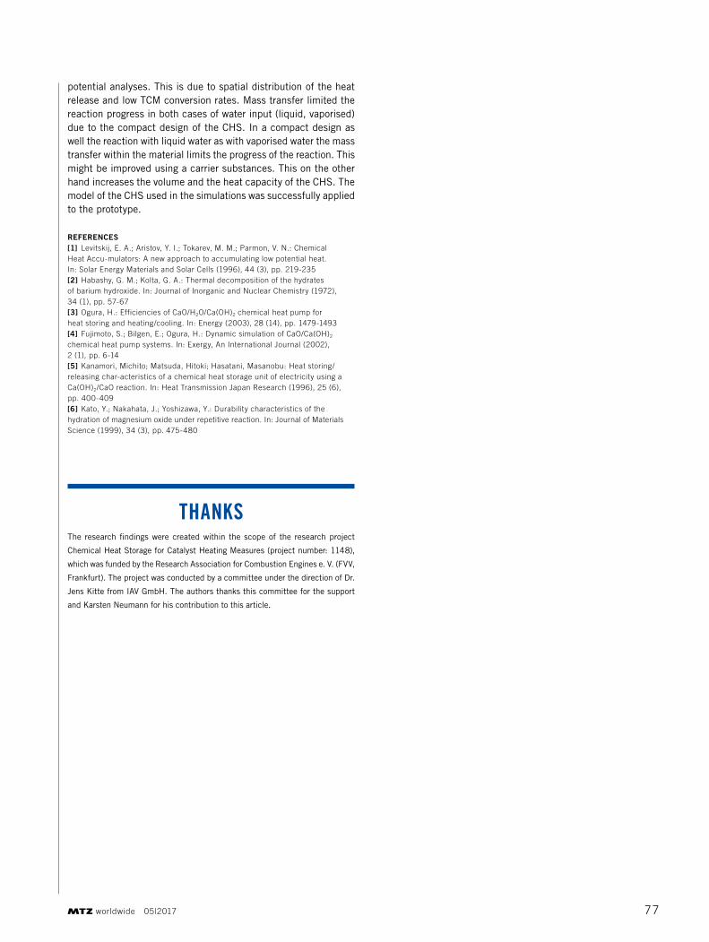
After the measurements were performed, the results were com-pared to the simulation model. In FIGURE 5 (left), the measured and simulated temperatures downstream of the CHS are com-pared. The shape of the heat release function was not changed compared to the potential analysis. It becomes clear that the
results of simulation fit to the measurement. The mean temperature of the storage material, on the right, fits well, too. In this case, the released heat of the storage material is approximately 18 % of the theoretically available amount of energy. Still, the losses to the envi-ronment and the adjacent parts are taken into consideration. This means that only a small amount of the energy is released within the relevant period of time for the heating of the catalytic converter
8 SUMMARY AND OUTLOOK
The potential analyses showed the highest potential for CHS-Sys-tems in applications, in which enough time is available in order heating up the CHS. Furthermore, the best application for a CHS is given when a temperature drop of the EAS needs to be avoided.
The literature research of suitable materials identified calcium oxide and its reaction with water as the most promising thermochemical heat storage material for the application of preheating a catalytic converter with the necessary reaction temperatures. It shows great cycle stability at the microgram scale and a high heat storage capac-ity. The reaction with liquid water reached local discharging tem-peratures of more than 300 °C, the reaction with water vapor in conjunction with applied pressure of locally up to 450 °C. The mate-rial needs quite high charging temperatures of around 450 °C how-ever, which is why only the gasoline engine is a possible application for it. The discharging behaviour with liquid water is little known so far and more research is needed in this area.
Prototype tests revealed that the measured downstream of CHS and TCM bulk temperatures were below the temperatures of the
potential analyses. This is due to spatial distribution of the heat release and low TCM conversion rates. Mass transfer limited the reaction progress in both cases of water input (liquid, vaporised) due to the compact design of the CHS. In a compact design as well the reaction with liquid water as with vaporised water the mass transfer within the material limits the progress of the reaction. This might be improved using a carrier substances. This on the other hand increases the volume and the heat capacity of the CHS. The model of the CHS used in the simulations was successfully applied to the prototype.
REFERENCES[1] Levitskij, E. A.; Aristov, Y. I.; Tokarev, M. M.; Parmon, V. n.: Chemical Heat Accu-mulators: A new approach to accumulating low potential heat. In: Solar Energy Materials and Solar Cells (1996), 44 (3), pp. 219-235[2] Habashy, G. M.; Kolta, G. A.: Thermal decomposition of the hydrates of barium hydroxide. In: Journal of Inorganic and nuclear Chemistry (1972), 34 (1), pp. 57-67[3] Ogura, H.: Efficiencies of CaO/H2O/Ca(OH)2 chemical heat pump for heat storing and heating/cooling. In: Energy (2003), 28 (14), pp. 1479-1493[4] Fujimoto, S.; Bilgen, E.; Ogura, H.: Dynamic simulation of CaO/Ca(OH)2 chemical heat pump systems. In: Exergy, An International Journal (2002), 2 (1), pp. 6-14[5] Kanamori, Michito; Matsuda, Hitoki; Hasatani, Masanobu: Heat storing/releasing char-acteristics of a chemical heat storage unit of electricity using a Ca(OH)2/CaO reaction. In: Heat Transmission Japan Research (1996), 25 (6), pp. 400-409[6] Kato, Y.; nakahata, J.; Yoshizawa, Y.: Durability characteristics of the hydration of magnesium oxide under repetitive reaction. In: Journal of Materials Science (1999), 34 (3), pp. 475-480
THANKSThe research findings were created within the scope of the research project
Chemical Heat Storage for Catalyst Heating Measures (project number: 1148),
which was funded by the Research Association for Combustion Engines e. V. (FVV,
Frankfurt). The project was conducted by a committee under the direction of Dr.
Jens Kitte from IAV GmbH. The authors thanks this committee for the support
and Karsten Neumann for his contribution to this article.