Nassiri Toosi, A., et al.: Exhaust Gas Heat Recovery through Secondary … THERMAL SCIENCE, Year 2017, Vol. 21, No. 1B, pp. 729-743 729 EXHAUST GAS HEAT RECOVERY THROUGH SECONDARY EXPANSION CYLINDER AND WATER INJECTION IN AN INTERNAL COMBUSTION ENGINE by Ali NASSIRI TOOSI, Amir Hassan KAKAEE, and Hazhir EBNE-ABBASI* School of Automotive Engineering, Iran University of Science and Technology, Tehran, Iran Original scientific paper DOI: 10.2298/TSCI150915282N To enhance thermal efficiency and increase performance of an internal combus- tion engine, a novel concept of coupling a conventional engine with a secondary 4-stroke cylinder and direct water injection process is proposed. The burned gas- es after working in a traditional 4-stroke combustion cylinder are transferred to a secondary cylinder and expanded even more. After re-compression of the ex- haust gases, pre-heated water is injected at top dead center. The evaporation of injected water not only recovers heat from exhaust gases, but also increases the mass of working gas inside the cylinder, therefore improves the overall thermal efficiency. A 0-D/1-D model is used to numerically simulate the idea. The simula- tions outputs showed that the bottoming cycle will be more efficient at higher en- gines speeds, specifically in a supercharged/turbocharged engine, which have higher exhaust gas pressure that can reproduce more positive work. In the mod- eled supercharged engine, results showed that brake thermal efficiency can be improved by about 17%, and brake power by about 17.4%. Key words: internal combustion engine, water injection waste heat, secondary cylinder Introduction General trends nowadays are moving toward optimizing internal combustion engines and increasing fuel efficiency, due to the inadequacy of HC fuel resources and rigorous emis- sion regulations [1, 2]. It has been shown that a great portion of fuel heat energy is wasted through exhaust gases [3], so if we can recover some part of it, we can enhance overall thermal efficiency [4]. Many successful researches have been conducted in an attempt to recover the contained energy in exhaust gases and turn that into useful work. Dyer [5] noted that the effi- ciency of an internal combustion engine can be increased by using waste heat. It was also noted that exhaust system can be improved and cooling system can be simplified with 6-stroke engine. Conklin and Szybist [6] proposed a six-stroke internal combustion engine cycle with water in- jection for in-cylinder exhaust heat recovery which has the potential to significantly improve the engine efficiency and fuel economy. The design added two extra strokes to the conventional 4-stroke engines to recompress a portion of exhaust gases. They proposed to trap some exhaust gases after the exhaust stroke. After recompression, the water is injected and expands through –––––––––––––– * Corresponding author, e-mail: [email protected]
Transcript
Nassiri Toosi, A., et al.: Exhaust Gas Heat Recovery through Secondary … THERMAL SCIENCE, Year 2017, Vol. 21, No. 1B, pp. 729-743 729
EXHAUST GAS HEAT RECOVERY THROUGH SECONDARY EXPANSION CYLINDER AND WATER INJECTION
IN AN INTERNAL COMBUSTION ENGINE
by
Ali NASSIRI TOOSI, Amir Hassan KAKAEE, and Hazhir EBNE-ABBASI0F
*
School of Automotive Engineering, Iran University of Science and Technology, Tehran, Iran
Original scientific paper DOI: 10.2298/TSCI150915282N
To enhance thermal efficiency and increase performance of an internal combus-tion engine, a novel concept of coupling a conventional engine with a secondary 4-stroke cylinder and direct water injection process is proposed. The burned gas-es after working in a traditional 4-stroke combustion cylinder are transferred to a secondary cylinder and expanded even more. After re-compression of the ex-haust gases, pre-heated water is injected at top dead center. The evaporation of injected water not only recovers heat from exhaust gases, but also increases the mass of working gas inside the cylinder, therefore improves the overall thermal efficiency. A 0-D/1-D model is used to numerically simulate the idea. The simula-tions outputs showed that the bottoming cycle will be more efficient at higher en-gines speeds, specifically in a supercharged/turbocharged engine, which have higher exhaust gas pressure that can reproduce more positive work. In the mod-eled supercharged engine, results showed that brake thermal efficiency can be improved by about 17%, and brake power by about 17.4%. Key words: internal combustion engine, water injection waste heat,
secondary cylinder
Introduction
General trends nowadays are moving toward optimizing internal combustion engines and increasing fuel efficiency, due to the inadequacy of HC fuel resources and rigorous emis-sion regulations [1, 2]. It has been shown that a great portion of fuel heat energy is wasted through exhaust gases [3], so if we can recover some part of it, we can enhance overall thermal efficiency [4]. Many successful researches have been conducted in an attempt to recover the contained energy in exhaust gases and turn that into useful work. Dyer [5] noted that the effi-ciency of an internal combustion engine can be increased by using waste heat. It was also noted that exhaust system can be improved and cooling system can be simplified with 6-stroke engine. Conklin and Szybist [6] proposed a six-stroke internal combustion engine cycle with water in-jection for in-cylinder exhaust heat recovery which has the potential to significantly improve the engine efficiency and fuel economy. The design added two extra strokes to the conventional 4-stroke engines to recompress a portion of exhaust gases. They proposed to trap some exhaust gases after the exhaust stroke. After recompression, the water is injected and expands through
Nassiri Toosi, A., et al.: Exhaust Gas Heat Recovery through Secondary … 730 THERMAL SCIENCE, Year 2017, Vol. 21, No. 1B, pp. 729-743
evaporation, which results in recovery of wasted heat energy that would have been exhausted to atmosphere before and producing more positive work. Many patents are registered trying to manipulate this idea to achieve higher efficiencies [7-11]. An experimental work which is done by Arabaci et al. [12] showed that brake specific fuel consumption (BSFC) is decreased by 9% and power output increased by 10% in a 6-stroke engine. In another study, Keromnes et al. [13] developed a 5-stroke turbocharged (TC) engine which consists of two high pressure cylinders and a secondary low pressure expansion cylinder. The combustion cylinder has lower compres-sion ratio which allows turbocharging. The transferred exhaust gases expand more in the low pressure secondary cylinder. By incorporating this idea, an experimental model was developed. The results show an increase in thermal and fuel conversation efficiency. The fuel conversion efficiency of 36.1% was achieved, and the optimum BSFC was below 217 g/kWh. Liu et al. [14] proposed a secondary expansion cylinder, which has the potential to let the exhaust gas fur-ther expand inside for energy recovery. The expanders have no intake valve and always open to the exhaust manifold of firing cylinders and the expanders work as two stroke: expansion and exhaust. Their analysis showed that the idea is only applicable to the high load condition of heavy engines with high boosted pressure and the energy recovery potential is very limited. Lu et al. [15] proposed a 2/4 strike switchable secondary expansion internal combustion engine. By varying the valve timing, the expansion cylinder could switch its working mode between 2- and 4-stroke to obtain optimum energy conversion efficiency in different engine speeds. Their ex-periment results showed that the proposed engine could save fuel up to 10-18% in all frequently used working condition of a general internal combustion engine.
Bottoming cycles utilization, e. g. Rankine cycles [16, 17] or Brayton air cycles is another example of waste heat recovery from exhaust gases. The first one includes various forms of Rankine cycles. Yu et al. [16] simulated a model based on an actual organic Rankine cycle (ORC) bottoming system of a Diesel engine. Their results indicated that approximately 75% and 9.5% of wasted heat from can be recovered, respectively, from exhaust gases and jacket water. They also concluded that the thermal efficiency of that particular Diesel engine could be improved up to 6.1%. Liu et al. [18] showed that famous automotive companies, Honda and BMW for instance, are working on such cycles, reporting that they have cut the fuel consumption by 10%. The same results have been reported for Cummins by using these cycles in their commercial trucks. In another study, Fu et al. [19] used Rankine cycle in an open steam power cycle. By using exhaust gases heat, steam is produced and then injected in-to expansion cylinder and expands in the cylinder. Their research demonstrated that exhaust gas temperature was the limiter of recovery process, and that the engine thermal efficiency could be improved by 6.3% at 6000 rpm. In another study, Fu et al. [20] studied on exhaust heat recovery by using a steam-assisted turbocharger. It is expected that engine brake torque increased by 25%.
In this paper, it is proposed to combine two different techniques in exhaust heat recov-ery: secondary cylinder and water injection. The exhaust gases from a traditional 4-stroke work-ing cycle are transferred to a secondary 4-stroke cylinder to be expanded even more. Also by recompression of the exhaust gases (in the coupled cylinder) and water injection process at TDC, expansion of the resulting steam/exhaust mixture results in the overall engine thermal efficiency improvement. In fact, working fluids go through 8-strokes in two continuous 4-stroke cylinders.
To increase recovering efficiency, injected water is preheated by using jacket water and exhaust gases to recover heat from these two heat sources. The overall effect of this idea was investigated on engine performance in a commercial 4-cylinder spark ignition internal combustion engine in both naturally aspirated (NA) and supercharged (SC) operation modes.
Nassiri Toosi, A., et al.: Exhaust Gas Heat Recovery through Secondary … THERMAL SCIENCE, Year 2017, Vol. 21, No. 1B, pp. 729-743 731
To find the upper boundary potential of this idea, the engine is considered to work in full load condition. In this mode, exhaust gases have more potential to evaporate water in order to in-crease power, thermal efficiency, and energy recovery limit.
Principles
Principles of bottoming cycles
The fuel conversion efficiency of an internal combustion engine is calculated by di-viding mechanical power delivered by the engine (which is calculated from the torque, T, and rotation speed, ω) with the fuel chemical power, calculated from mass flow rate of fuel, ṁf, and the lower heating value, (LHV) [21]:
f
fTLHVmωη =
(1)
The maximum fuel conversion efficiency of an internal spark ignited combustion engine is about 30-33% [22]. Thermal losses are the main source of the engine power losses. For most of the engines, about one third of the fuel energy is lost through in-cylinder heat transfer and another one third of the fuel energy is lost in the exhaust gases [6]. Insulating cyl-inders walls is not an effective way to reduce heat transfer loss, because it increases in-cylinder temperature and increases exhaust energy loss [4]. Recovering waste heat from ex-haust gases and enhancing expansion ratio are other ways to improve efficiency.
Exhaust heat recovery or exhaust energy recovery (EER) is divided into two sub-categories: direct and indirect. Direct exhaust heat recovery methods are dependent upon the pressure energy of exhaust gases, and is achieved by re-expansion of the gases through expand-ers. Because of limited expansion ratio and operation speed range of engines, re-expansion of exhaust gases has a great potential to make gases expand further in order to recover waste heat energy. The reason for that is that higher compression ratio means higher overall compression ratio, ϵ, which ends in higher thermal efficiency, as it described in eq. (2):
111T γη −= −
(2)
However, due to the kinematics of the pistons, the compression ratio is the same for both expansion and compression process. In an internal combustion engine compression ratio is limited by the mechanical stress and knock phenomenon. So having higher expansion ratio dur-ing expansion process is another way of increasing thermal efficiency. Various methods are in-vented to use this kind of energy: including turbocharging, secondary expansion cylinders, etc.
On the other hand, indirect methods depend on exhaust gases heat energy and are based on bottoming thermodynamic cycles. The exhaust gases extracted heat is transferred in-directly by heat transfer to a secondary cycle, which is then used to run a bottom cycle. These methods rely on secondary cycles which couple with the exhaust system. In order to reduce the resulting back pressure, special attention is required in designing these cycles to prevent any major power loss [14].
The basics of secondary expansion with water expansion
If one can use a method in which both thermal and pressure energy of exhaust gases are recovered, a big portion of waste heat energy can be converted into useful work. In this pa-
Nassiri Toosi, A., et al.: Exhaust Gas Heat Recovery through Secondary … 732 THERMAL SCIENCE, Year 2017, Vol. 21, No. 1B, pp. 729-743
per, by using a secondary cylinder, the exhaust gases can expand more and hence more pressure energy is converted into useful work. Furthermore, by using water injection and its evaporation, heat energy of exhaust gases is recovered too. It is tried to modify 6-stroke engines by using a secondary cylinder to re-compress and re-expansion of exhaust gases from a traditional 4-stroke engine. Unlike the 6-stroke engines which all strokes occur in one cylinder, the idea is to re-expand the exhaust gases even more and use most of the exhaust gases in a geometrically opti-mized secondary cylinder to achieve higher recovery efficiency and higher power output. The goal is to optimize secondary cylinder, both from compression ratio and volume point of view. Also by optimizing the effective parameters, like valve timings in both cylinders and the trans-fer ports (connecting exhaust port of first cylinder to the inlet port of secondary cylinder), the existed back-pressure will be minimized. In the following sections, the bottom cycle is analyzed separately from two viewpoints: secondary expansion and water injection.
Secondary expansion
The expander device can be a special expander (turbines for example, or cylinders in this context) that is mounted at the end of exhaust system. In the bottoming cycle, the engine exhaust gases are expanded more in the expander cylinder to produce work (expansion work). Figure 1 shows the general concept of secondary expansion cycle, in which some of the cyl-inders are considered only to re-expand exhaust gases. Figure 1(a) depicts the base 2-cylinder engine with no expander cylinders. That is to say, the base engine is a 4-cylinder engine that is converted into a 2-cylinder for our study. More information is given in the next section about the base engine. Figure 1(b) depicts the base engine with two expander cylinders. Cyl-inders #1 and #2 are combustion cylinders, and #3 and #4 are the expander cylinders. It can be seen in the figure that the inlet ports of the expanders are directly connected to the exhaust ports of the combustion cylinders through the transfer port.
Figure 1. Schematic of (a)conventional and (b) modified engine (with secondary cylinders)
The combustion cylinders are acting parallel and similar with each other except for a relative 360° crank angle (CA) spark ignition delay. The expander cylinders work in 4-stroke mode with –180 °CA or 540 °CA delay relative to their correspond combustion cylinders. In other words, when the combustion cylinder works in exhaust stroke, the corresponding expand-er cylinder must be in intake stroke. The operating order of the cylinders is shown in tab. 1. The important fact that needs special attention is the design and the volume of the transfer port. This pipe which connects two cylinders with two different pressures, reduces the compression ratio
Nassiri Toosi, A., et al.: Exhaust Gas Heat Recovery through Secondary … THERMAL SCIENCE, Year 2017, Vol. 21, No. 1B, pp. 729-743 733
so as for the exhaust gases to expand while being transferred through the pipe, without produc-ing any useful work. Great attention is needed in designing this port, because this volume is ac-counted as dead volume in the global expansion ratio [13]. Furthermore, the design of the port directly influences the gas stream. Critical parameters like the volume and the length of the pipe are needed to be carefully optimized, which will be presented in the section Optimization.
Table 1. Operating order of bottoming cycle with secondary cylinders, fig. 1(b)
Water injection
There are many applications for water injection in internal combustion engines litera-tures. For example, using this idea helps to reduce NOx pollutant in heavy Diesel engines which can easily satisfy pollution standards like Euro V [23]. Also, water injection can be used to in-crease stability in higher compression ratios in gasoline direct injection (GDI) engines [24-26]. The charge cooling effect of the water injection evaporation is used to reduce in-cylinder tem-perature and pressure. This allows for more effi-cient spark timings, due to reduced knock sensi-tivity [24, 25]. There is also another application in controlling hydrogen engines to control the burn-ing rate under heavy working condition [27]. The point is that the injected mass is about 30-50% of injected fuel and the engine does not benefit enough from expansion work which is caused by water evaporation [27].
In the current bottoming cycle, water injec-tion is done at TDC in the secondary cylinder. After the injection of water into the compressed burnt hot gases, water droplets are vaporized by using waste heat energy of gases from previous cylinder [28]. A slight increase in-cylinder pres-sure is noticeable when the water has instantly vaporized, fig. 2. Also, the vaporization of water droplets is done instantly after injecting wa-ter on warmer surfaces. This process is called Leidenfrost effect [29, 30]. So the second ex-pansion stroke is acquired. The evaporated water enhances the cylinder pressure which ends in improving efficiency and enhancing output work. Actually, water injection process im-proves the efficiency of cycle in two ways: – First, injected water (in both liquid and vaporized states) increases the working mass of the
cylinder and turns the heat of hot gases into in-cylinder pressure which results in positive output work. As we know, output temperature of exhaust gases can reach up to 900 °C at high load operation in spark ignition engines [21]. In normal conditions this huge source
Stroke 1 Stroke 2 Stroke 3 Stroke 4
Cylinder 1 Exhaust Intake Compression Expansion
Cylinder 2 Intake Compression Expansion Exhaust
Cylinder 3 Compression Expansion Exhaust Intake
Cylinder 4 Expansion Exhaust Intake Compression
Figure 2. The effect of water injection on the secondary cylinder pressure
Nassiri Toosi, A., et al.: Exhaust Gas Heat Recovery through Secondary … 734 THERMAL SCIENCE, Year 2017, Vol. 21, No. 1B, pp. 729-743
of heat is discharged into the atmosphere. But with this method we can use this energy source to evaporate water, but a 300 °C limitation exists, which will be discussed later.
– Second, the injected hot water contains recovered energy from waste heats. It is obvious that the specific enthalpy of injected water is increased with increasing water temperature. Therefore, higher injected water temperature leads to elevated cylinder pressure and hence the output power.
As previously mentioned, increasing injected water temperature leads to increased cy-cle efficiency. Wu et al. [27] showed that by increasing injected water temperature, evaporation duration and its start lag will be minimized. By preheating water, injected water reaches its satu-
ration temperature and its in-cylinder evapo-rations takes less time. It is possible to pre-heat water up to 100 °C easily, using water to water heat exchangers, especially as jacket water temperature is normally at 105 °C. Al-so by using gas to liquid heat exchangers, it is possible to heat water up to 200 °C under pressure [27]. So the proposed cycle can re-cover heat from two sources: jacket water (by pre-heating the water) and exhaust gases (by pre-heating and in-cylinder water vaporiza-tion). Figure 3 schematically illustrates the firing cylinder along with the secondary cyl-inder and water injection. In this study, the water injection temperature is considered to be from 0 °C to 200 °C in order to examine the effect of injected water temperature on
the cylinder output work. Also, the 200 °C temperature is assumed to be achievable to show the upper boundary potential of the idea.
Modeling
Calculation method
In this study, simulation is based on an object-based code program, called GT-Po-wer. This program is capable of simulating a wide range of issues related to vehicle and en-gine performance. The solution is based on 1-D fluid dynamics, representing the flow and heat transfer in the piping and other flow components of an engine system. Furthermore, the code contains many other specialized models required for system analysis [31].
To model the base engine, basic parameters of the engine, including its geometry and specifications, should be measured experimentally. In this research, the required data are provided by the engine producer.
Boundary conditions
In this section, the aim is to use the parameters as realistic and precise as possible in order to build up a realistic solution. To start the simulation, a base engine is needed. The selected engine for the study is a four cylinder NA 1.7 liter engine, named EF7, devel-oped and produced by Iran Khodro Company, Theran, Iran (IKCO). The SC engine is numer-ically and experimentally developed in another study [32]. In the GT-Power SC
Figure 3. Schematic view of an engine with secondary cylinder and water injection [27]; 1 – fuel, 2 – feed water pump, 3 – water source, 4 – combustion cylinder, 5 – expansion cylinder with water injection, 6 – 1st feed water heater, 7 – 2nd feed water heater
Nassiri Toosi, A., et al.: Exhaust Gas Heat Recovery through Secondary … THERMAL SCIENCE, Year 2017, Vol. 21, No. 1B, pp. 729-743 735
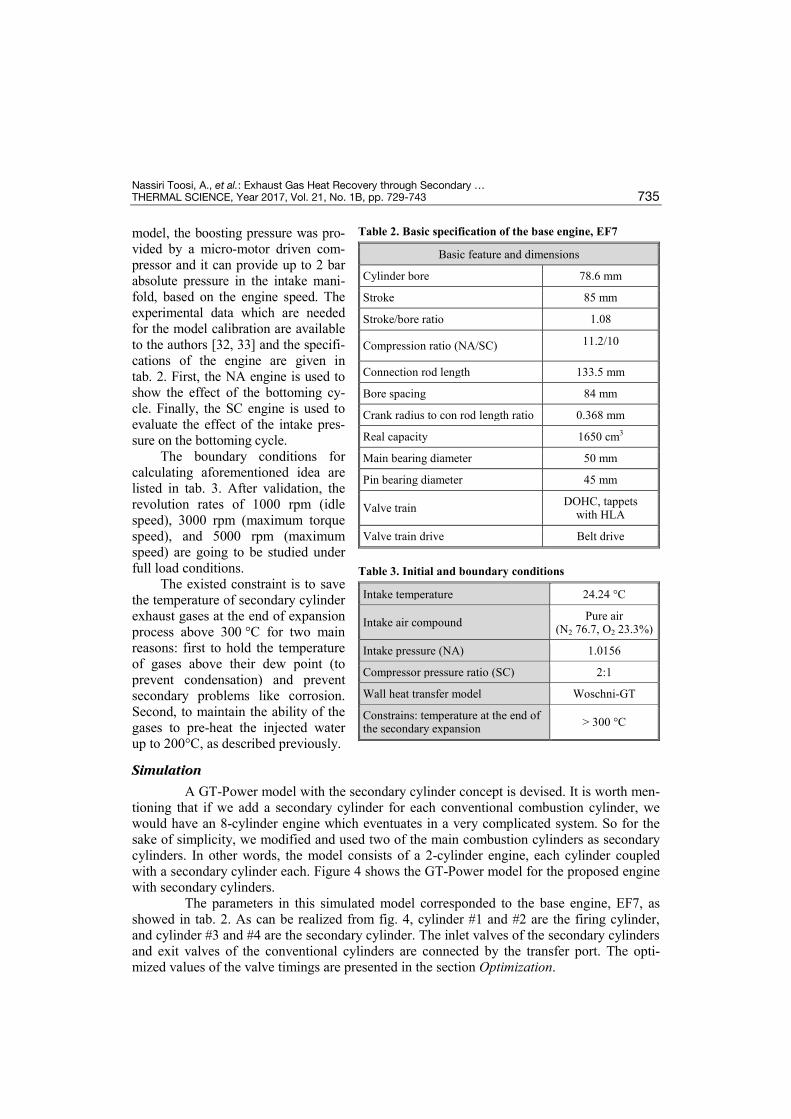
model, the boosting pressure was pro-vided by a micro-motor driven com-pressor and it can provide up to 2 bar absolute pressure in the intake mani-fold, based on the engine speed. The experimental data which are needed for the model calibration are available to the authors [32, 33] and the specifi-cations of the engine are given in tab. 2. First, the NA engine is used to show the effect of the bottoming cy-cle. Finally, the SC engine is used to evaluate the effect of the intake pres-sure on the bottoming cycle.
The boundary conditions for calculating aforementioned idea are listed in tab. 3. After validation, the revolution rates of 1000 rpm (idle speed), 3000 rpm (maximum torque speed), and 5000 rpm (maximum speed) are going to be studied under full load conditions.
The existed constraint is to save the temperature of secondary cylinder exhaust gases at the end of expansion process above 300 °C for two main reasons: first to hold the temperature of gases above their dew point (to prevent condensation) and prevent secondary problems like corrosion. Second, to maintain the ability of the gases to pre-heat the injected water up to 200°C, as described previously.
Simulation
A GT-Power model with the secondary cylinder concept is devised. It is worth men-tioning that if we add a secondary cylinder for each conventional combustion cylinder, we would have an 8-cylinder engine which eventuates in a very complicated system. So for the sake of simplicity, we modified and used two of the main combustion cylinders as secondary cylinders. In other words, the model consists of a 2-cylinder engine, each cylinder coupled with a secondary cylinder each. Figure 4 shows the GT-Power model for the proposed engine with secondary cylinders.
The parameters in this simulated model corresponded to the base engine, EF7, as showed in tab. 2. As can be realized from fig. 4, cylinder #1 and #2 are the firing cylinder, and cylinder #3 and #4 are the secondary cylinder. The inlet valves of the secondary cylinders and exit valves of the conventional cylinders are connected by the transfer port. The opti-mized values of the valve timings are presented in the section Optimization.
Table 2. Basic specification of the base engine, EF7
Basic feature and dimensions
Cylinder bore 78.6 mm
Stroke 85 mm
Stroke/bore ratio 1.08
Compression ratio (NA/SC) 11.2/10
Connection rod length 133.5 mm
Bore spacing 84 mm
Crank radius to con rod length ratio 0.368 mm
Real capacity 1650 cm3
Main bearing diameter 50 mm
Pin bearing diameter 45 mm
Valve train DOHC, tappets with HLA
Valve train drive Belt drive
Table 3. Initial and boundary conditions
Intake temperature 24.24 °C
Intake air compound Pure air (N2 76.7, O2 23.3%)
Intake pressure (NA) 1.0156
Compressor pressure ratio (SC) 2:1
Wall heat transfer model Woschni-GT
Constrains: temperature at the end of the secondary expansion > 300 °C
Nassiri Toosi, A., et al.: Exhaust Gas Heat Recovery through Secondary … 736 THERMAL SCIENCE, Year 2017, Vol. 21, No. 1B, pp. 729-743
Figure 4. The GT-Power model for the proposed engine with the secondary cylinder
It is obvious that adding the secondary cylinders and their water injectors leads to an increase in the number of the required parameters including mass, the spray timing, and the temperature of the injected water, geometry and compression ratio of the secondary cylinders, lift and the timing of the intake and exhaust valves, as well as, volume, length and geometry of the transfer port, etc. In order to make use of the maximum potential of the idea, it is re-quired to optimize each part of the system efficiently.
Base model validation
To validate the model, important engine performance parameters like brake power and BSFC (total fuel mass flow rate divided by total brake power of the engine) for the NA engine and in-cylinder peak pressure and break torque for the SC engine were verified by the experimental data. Figures 5 and 6 illustrate the validated output data for NA engine and figs. 7 and 8 for SC engine.
Figure 5. Brake power vs. engine speed (rpm) for validating NA engine
Figure 6. The BSFC vs. engine speed (rpm) for validating NA engine
Nassiri Toosi, A., et al.: Exhaust Gas Heat Recovery through Secondary … THERMAL SCIENCE, Year 2017, Vol. 21, No. 1B, pp. 729-743 737
Figure 7. Maximum in-cylinder pressure vs. engine speed (rpm) for validating SC engine
Figure 8. Brake torque vs. engine speed (rpm) for validating SC engine
The results show reasonable agreement between simulated model and experimental da-ta, so the engine model is assumed to be sufficiently reliable to be used in the following study.
Optimization
Optimizations are carried out using GT-Power optimization tool, however, valve timings are optimized using genetic algorithm (GA) through coupling GT-Power with MATLAB SIMULINK. Every single pair of newly added parameters is optimized to ensure using the maximum potential of the engine. Ultimately, the performance parameters of the base engines (NA and SC) are com-pared with the new 2-cylinder model under various conditions defined by multiple out-put parameters. Although most of the pa-rameters are optimized, only the most im-portant and effective ones are presented in this section. Figure 9 shows the optimiza-tion of the transfer port. As the length of the pipe is shortened, the output power in-creases. Such a result was predictable, be-cause as the length of the pipe increases, the gases are more expanded while passing the transfer port, which end in less exhaust pressure and less expansion work by the secondary cylinder. As a dead volume, the length of the port should be as short and as logical as possible, because very small pipe lengths are not applicable in the reality and are restricted by geometry of the engine.
In our case, having considered the geometry of the engine block, the minimum length of the transfer port was considered to be about 20 mm.
The volume of the secondary cylinder directly affects the output results, so it should be optimized precisely. Figure 10 illustrates the result of the optimization. As can be seen, the output power reaches its maximum point, where the secondary cylinder’s volume is almost twice as much as the combustion cylinders. Increasing the secondary cylinder volume in-creases the trapped exhaust gases volume (less back pressure for upstream cylinder) and also
Figure 9. Transfer port length vs. brake power
Nassiri Toosi, A., et al.: Exhaust Gas Heat Recovery through Secondary … 738 THERMAL SCIENCE, Year 2017, Vol. 21, No. 1B, pp. 729-743
reduces the compression work. But large volumes lead to increasing the friction sur-faces and lowers the output works.
Valve timings are one of the most im-portant parameters in optimizing the model. Since inlet valves and exhaust valves af-fects the cylinder trapped mass simultane-ously, double parameter optimization is needed. To do so, MATLAB is linked through SIMULINK to use MATLAB’S GA optimization tool. The valve timings directly influence the ignition cylinder back pressure and the cylinder trapped mass and having a precise optimization, minimizes
the backpressure. Figure 11 shows the optimized results for secondary cylinder valve timings. There is a 30 °CA overlap
period in the valve timing of 3 valves during the exhaust gases transferring process. During this period, the exhaust valve of the firing cylinder, inlet and exhaust valves of the secondary cylinders are open, which helps to expel the exhaust gases directly from the ignition cylinder to the sec-ondary cylinder, fig. 11. Never-theless, the mass of the trapped gases in the secondary cylinder is less than the total mass of the fir-ing cylinder exhaust gases. How-ever, the expansion ratio of the trapped mass in the secondary
cylinder is more than the combustion cylinder expansion ratio, due to its larger volume. So the trapped gases in the secondary cylinder are further expanded to form a Miller cycle. This process helps to increase the engine thermal efficiency.
The last parameter to be optimized is water injection timing. It was mentioned be-fore that ideally the injection should be done at TDC. But as we know, this can not be hap-pened, due to the injectors’ mass flow rate limitation. So, injection process should be started bTDC. If the water injection process starts so early, compression work increases due to in-creasing in-cylinder working mass and in-cylinder pressure due to water evaporation. On the other hand, late water injection process leads to decreasing the produced work, since the water vaporization (and hence increase in the in-cylinder pressure) occurs once the cylinder has ex-perienced expansion. Figure 12 shows the variation of the engine output power with different water injection timings. The optimized CA for each engine speed as well as engine type (NA or SC) is different, due to the mass of injected water. For instance, the optimum value at 5000 rpm for NA engine is found to be 35° bTDC.
Figure 10. Volume (bore) of the secondary cylinder vs. brake power
Figure 11. Optimized valve timings (optimized by MATLAB'S GA)
Nassiri Toosi, A., et al.: Exhaust Gas Heat Recovery through Secondary … THERMAL SCIENCE, Year 2017, Vol. 21, No. 1B, pp. 729-743 739
Results and analysis
Figures 13-17 compare the output results of the base NA engine (EF7) with the output results of modified engine (with secondary cylinder and water injector) in NA operation mode and full load condition. Comparing the outputs between these two engines, it can be noted that the brake power output has increased by 19% and also that BSFC has decreased by 15% at high engine speeds (5000 rpm). We must say, these results are not similar in low engine speeds. As can be seen, in low engine speeds, not only brake power decreases but BSFC increases as well. The rea-son originates from the fact that at high engine speeds and thus higher energy levels, exhaust gases mass flow rate is higher and hence are ca-pable of vaporizing more water, so that the friction of the secondary cylinder becomes negligible. However, it is obvious that the produced work by the secondary cylinder can not
Figure 13. Brake power vs. engine speed for NA engines
Figure 14. Brake torque vs. engine speed for NA engines
Figure 15. Brake efficiency vs. engine speed for NA engine
Figure 16. Comparison of trapped mass in both NA mode and SC mode in secondary cylinder (both at 5000 rpm)
Figure 12. Optimization of water injection timing for NA engine at 5000 rpm
Nassiri Toosi, A., et al.: Exhaust Gas Heat Recovery through Secondary … 740 THERMAL SCIENCE, Year 2017, Vol. 21, No. 1B, pp. 729-743
overshadow the extra friction in lower engine speeds. This leads to reduced net power and in-creased engine BSFC. Secondly, the exhaust pressures of the combustion cylinders are higher for higher loads, which can be expanded more to produce more work. But for lower loads, the produced work is so low that can not overcome the secondary cylinder friction. So, if the sec-ondary cylinder’s overall expansion work (exhaust gases re-expansion and expansion of steam/gases) is greater than the sum of negative compression work and the additional friction work, the secondary cylinder’s overall power output will be positive. At higher speeds, sec-ondary cylinder produces more power than is required to overcome compression work and its friction, which results in higher power and lower BSFC of the engine.
According to the discussion, it is expected to have higher engine thermal efficiency in higher speeds and lower thermal efficiency in lower speeds, as can be seen in fig. 17.
As previously described, the problem of power reduction at lower speeds stems from lower energy content of the exhaust gases that leads to lower water evaporation and over-weighting the cylinder friction. It is clear that these results are obtained in full load condition, but in normal engine operation, which most of the time engine works in part load condition and low engine speeds, the bottoming cycle achievement and energy recovery potential are very limited.
In order to obviate this problem, we run a series of simulations based on the same bottoming cycle for the base SC engine. After the necessary optimizations as for the NA en-gine, we ensure that the system uses its maximum potential to recover waste heat. The point is that in the SC engine, larger mass flow rate of exhaust gases are available at higher pressures, so the secondary cylinder deal with larger amount of gases with higher inlet pressure, as illus-trated in fig. 16.
Higher trapped mass in the secondary cylinder means higher ability to evaporate more water, but also higher work is needed to compress the exhaust gases. So a tradeoff has to be made between the amount of the trapped mass and the negative work needed to compress the trapped mass. Overlap of cylinder valves is the key to trap optimum amount of the exhaust gases in the cylinder. The next criterion is the amount of injected water. Technically we can inject as much as water into the secondary cylinder to be evaporated. But there exists an opti-mum mass of injected water based on the energy content of the gases as well as gas/steam temperature before the exhaust gas opening. But does higher mass of injected water always increase output power?
Figure 17 shows the engine brake power vs. injected water mass. We found out that at any rpm, there is an optimized value for injected water mass in which the engine power output reaches its maximum. The reason is that the in-cylinder gases reach their dew point at a specific mass and become saturated and by increasing the amount of injected water mass, the excessive water can not be evaporated anymore. Also, the excessive amount of water makes the vaporized water condensed, which leads to decreased in-cylinder pressure and lowering output work. Fur-thermore, condensation should be avoided, because of secondary problems like erosion and oth-
Figure 17. Diagram of injected water mass vs. brake power at 5000 rpm (NA engine)
Nassiri Toosi, A., et al.: Exhaust Gas Heat Recovery through Secondary … THERMAL SCIENCE, Year 2017, Vol. 21, No. 1B, pp. 729-743 741
er technical problems which are likely to arise. So an appropriate and optimized amount of wa-ter mass should be obtained for each engine speed and working condition.
Figure 18 shows the effect of water injec-tion on the in-cylinder gases temperature. As stated before, the in-cylinder temperature is kept above 300 °C to avoid condensation.
Figures 19 and 20 compare the results of the base SC engine with the results of the modi-fied engine (with the bottoming cycle). It can be seen in fig. 19 that, in comparison with NA engine, the problem of decreased power in low-er speeds is resolved and the power increases in all speeds. The gained results were expected, since the inlet pressure for the secondary cylinder is increased which results in higher re-expansion work, higher water evaporation ability and higher output power. For example, even at 1000 rpm, the brake power has increased by 4%. At 3000 and 5000 rpm, the brake power increases by 11 and 17%, respectively.
Since the brake power increases in all engine speeds, we expect to have lower BSFC in all engine speeds as well. It is also noteworthy to mention that the increased power is gained by no extra fuel just by recovering waste heat. So it is obvious that system efficiency can be improved by the same logic.
Figure 20 illustrates the efficiency improvement over all engine speeds. The engine efficiency is increased by +17% at 5000 rpm and +11% at 1000 rpm.
Figure 19. Diagram of brake power vs. engine speed for SC engine
Figure 20. Diagram of system brake efficiency vs. engine speed for SC engine
According to presented analysis and results, it can be deduced that the bottoming cycle is more effective when the engine operates in boosted operation modes, e. g. TC or SC engines. So it is more applicable to high load conditions of boosted engines. Although the original idea of this type of engine is for automotive applications, the NA engine may be more suitable for power generation in industries and commercial buildings, when a permanent source of water is available and it can be operated constantly in full load operating mode and
Figure 18. The effect of water injection on the in-cylinder temperature in SC engine (full load condition at 5000 rpm)
Nassiri Toosi, A., et al.: Exhaust Gas Heat Recovery through Secondary … 742 THERMAL SCIENCE, Year 2017, Vol. 21, No. 1B, pp. 729-743
higher engine speeds. On the other hand, SC engine with bottoming cycle is more promising and covers most frequently-used condition for a general vehicle boosted engine, which makes it applicable to automotive applications.
Although Liu et al. [14] showed that simple expanders have very limited effective work range and energy recovery potential, but the current results show that our set-up can be a simple and effective way to recover waste heat when accompanied by water injection concept.
Conclusions
• In the present study, a novel idea is utilized to combine a secondary cylinder with water injection concept in order to recover the waste engine heat from two sources, namely, the exhaust gases heat and the cooling water. A secondary cylinder is used to re-expand ex-haust gases even more and to recompress them to prepare them for water injection. A di-rect water injector is used to inject water at TDC. By evaporating the injected water, in-jected into the hot compressed exhaust gases, the working mass of the expander and its’ in-cylinder pressure is increased to increase the engine output power. A 0-D/1-D model is set-up to simulate the idea. The individual system parameters have been optimized to en-sure using the system maximum potential. The results showed that in NA engine the bot-toming cycle can only improve system efficiency at high engine speeds. At low engine speeds, friction forces are dominant and the net power generally decreases due to the low energy content of the exhaust gases.
• A solution for reduction of net power at lower engine speed is to use the same idea in a boosted engine.
• In SC engine, higher inlet pressures cause the exhaust pressure (and so as enthalpy) to be higher. So in lower engine speeds, the gases have higher re-expansion ability and higher content of energy in order to evaporate more amount of water in the secondary cylinder.
• These results demonstrate that the idea of using a secondary cylinder with water injection can improve system efficiency and lower BSFC in all engine speeds in SC engines.
• It is expected that this concept acts more efficiently in boosted heavy Diesel engines, which have higher compression ratios and their full load operations stretch over longer periods of time. Also, using the aforementioned bottoming cycle for power generators in industries and commercial buildings is proposed.
• To have more precise picture of new engine performance, the cost of increasing the tem-perature of injected water (using cooling water), as well as, the effect of water and added tools masses on automotive total mass and performance should be studied.
References [1] Chiara, F., Canova, M., A Review of Energy Consumption, Management, and Recovery in Automotive
Systems, with Considerations of Future Trends, Proc. Inst. Mech. Eng. Part D J. Automob. Eng., 227 (2013), 6, pp. 914-936
[2] Ortmeyer, T. H., Pillay, P., Trends in Transportation Sector Technology Energy Use and Greenhouse Gas Emissions, Proc. IEEE, 89 (2001), 12, pp. 1837-1847
[3] Saidur, R. et al., Technologies to Recover Exhaust Heat from Internal Combustion Engines, Renew. Sustain. Energy Rev., 16 (2012), 8, pp. 5649-5659
[4] Taymaz, I., An Experimental Study of Energy Balance in Low Heat Rejection Diesel Engine, Energy, 31 (2006), 2–3, pp. 364-371
[5] Dyer, L., Internal-Combustion Engine, US Patent 1339176 A, USA, 1920 [6] Conklin, J. C., Szybist, J. P., A Highly Efficient Six-Stroke Internal Combustion Engine Cycle with
Water Injection for In-Cylinder Exhaust Heat Recovery, Energy, 35 (2010), 4, pp. 1658-1664
Nassiri Toosi, A., et al.: Exhaust Gas Heat Recovery through Secondary … THERMAL SCIENCE, Year 2017, Vol. 21, No. 1B, pp. 729-743 743
[7] Fiveland, S., Six-Stroke Engine System with Blowdown Exhaust Recirculation, US Patent number 2014/0158084 A1, Peoria, Ill., USA, 2014
[8] Tsukahara, E., Six-Stroke Engine, US Patent 2014/0224195 A1, Peoria, Ill., USA, 2014 [9] Eriksson, S., Six Stroke Engine, EU Patent 2 476 879 B1, Kungalv, Sweden, 2012 [10] Williams, D. R., Six-Stroke Engine Exhaust Gas Recirculation System and Method, USA Patent
2014/0158100 A1, Peoria, Ill., USA, 2014 [11] Szybist, J. P., Conklin, J. C., Highly Efficient 6-Stroke Engine Cycle with Water Injection, US Patent
8,291,872 B2, Oak Ridge, Tenn., USA, 2012 [12] Arabaci, E., et al., Experimental Investigation of the Effects of Direct Water Injection Parameters on
Engine Performance in a Six-Stroke Engine, Energy Convers. Manag., 98 (2015), July, pp. 89-97 [13] Keromnes, A., et al., Development and Validation of a 5 Stroke Engine for Range Extenders
Application, Energy Convers. Manag., 82 (2014), Jun, pp. 259-267 [14] Liu, J. P., et al., Comparison and Analysis of Engine Exhaust Gas Energy Recovery Potential Through
Various Bottom Cycles, Appl. Therm. Eng., 50 (2013), 1, pp. 1219-1234 [15] Lu, Y., et al., An Evaluation of a 2/4-Stroke Switchable Secondary Expansion Internal Combustion
Engine, Appl. Therm. Eng., 73 (2014), 1, pp. 325-334 [16] Yu, G., et al., Simulation and Thermodynamic Analysis of a Bottoming Organic Rankine Cycle (ORC)
of Diesel Engine (DE), Energy, 51 (2013), Mar., pp. 281-290 [17] Boretti, A., Recovery of Exhaust and Coolant Heat with R245fa Organic Rankine Cycles in a Hybrid
Passenger Car with a Naturally Aspirated Gasoline Engine, Appl. Therm. Eng., 36 (2012), Apr., pp. 73-77 [18] Liu, J. P., et al., Comparison and Analysis of Engine Exhaust Gas Energy Recovery Potential Through
Various Bottom Cycles, Appl. Therm. Eng., 50 (2013), 1, pp. 1219-1234 [19] Fu, J., et al., An Open Steam Power Cycle Used for IC Engine Exhaust Gas Energy Recovery, Energy,
44 (2012), 1, pp. 544-554 [20] Fu, J., et al., An Approach for Exhaust Gas Energy Recovery of Internal Combustion Engine: Steam-
assisted Turbocharging, Energy Convers. Manag., 85 (2014), Sep., pp. 234-244 [21] Heywood, J. B., Internal Combustion Engines Fundamentals, McGraw-Hill, New York, USA, 1988 [22] Caton, J. A., The Thermodynamic Characteristics of High Efficiency, Internal-Combustion Engines,
Energy Convers. Manag., 58 (2012), Jun., pp. 84-93 [23] Tesfa, B., et al., Water Injection Effects on the Performance and Emission Characteristics of a CI Engine
Operating with Biodiesel, Renew. Energy, 37 (2012), 1, pp. 333-344 [24] Bozza, F., et al., Potentials of Cooled EGR and Water Injection for Knock Resistance and Fuel
Consumption Improvements of Gasoline Engines, Appl. Energy, 169 (2016), May, pp. 112-125 [25] Hoppe, F., et al., Water Injection for Gasoline Engines: Potentials, Challenges, and Solutions, Int. J.
Engine Res., 17 (2016), 1, pp. 86-96 [26] Wilson, J. P., Effects of Water Injection and Increased Compression Ratio in a Gasoline Spark Ignition
Engine, University of Idaho, Moscow, Id., USA, 2011 [27] Wu, Z. J., et al., A High Efficiency Oxyfuel Internal Combustion Engine Cycle with Water Direct
Injection for Waste Heat Recovery, Energy, 70 (2014), Jun., pp. 110-120 [28] Arabaci, E., et al., Experimental Investigation of the Effects of Direct Water Injection Parameters on
Engine Performance in a Six-Stroke Engine, Energy Convers. Manag., 98 (2015), Jul., pp. 89-97 [29] Gradeck, M., et al., Heat Transfer for Leidenfrost Drops Bouncing onto a Hot Surface, Exp. Therm.
Fluid Sci., 47 (2013), May, pp. 14-25 [30] Paul, G., et al., Droplet Oscillation and Pattern Formation During Leidenfrost Phenomenon, Exp. Therm.
Fluid Sci., 60 (2015), Jan., pp. 346-353 [31] ***, GTIsoft, GT Power Engine Performance Application Manual, 7.3, Gamma Technologies, West-
mont, Ill., USA [32] Kasrayi, R., Supercharging EF7 Engine Based on the Operational Design Parameters by Using 1-D Si-
mulation (in Persian), MSc thesis, Iran University of Science and Technology, Tehran, 2013 [33] ***, IKCO – NPD Center, EF7 Engine NA Engine Performance Data, 2009. www.ip-co.com.