Abstract These investigations were carried out on silo models, free-standing silos and silo batteries. The researches include the evaluation of value of pressure and temperature field on the silo wall as well as temperature gradient, registration of simultaneity of these loads. There were used sensors placed in the silo wall and bottom and sensors placed into material as sounder. The researches include either the evaluation of influences of the strength parameters of wall. Each of these investigated parameters is a random variable. Collection of such data as pressure, temperature, strengthen coefficients is of great significance, so the authors measured these loads many times. There is the need of calculation such quantities of statistics as characteristic, design value of measured loads and strength parameters, material and loads coefficient partial coefficient of safety, reliability indexes etc. These data were subjected to statistical accounts. The data obtained from calculations can be used in designing similar silos and in silo codes [1]. Keywords: silo, pressure, measurement, experiment, temperature, reliability 1. Introduction In general, two methods to determine bulk material pressures can be used, namely, the indirect and direct method. The indirect method consists of determining the strains in the silo structure, for example on the concrete surface or on the hoop reinforcing. But obtained in this way the tensile strains are very difficult to interpret in view of thermal, dynamic influence. Therefore, the above mentioned inadequacies of the indirect method have led to direct pressure investigations. The direct method was based on pneumatic, dynamometer, bonded wire strain gauge (used in ’70 and ’80), magneto elasticity sensors. The short history of development of this sensor constructions is described in [5,7]. One of the most applied pressure sensor, works on principle magneto elastic, was invented by research team [2] in ’80 and ’90 is shown in Fig. 1. The sensors are placed in the silo wall and bottom or during silo realization or they are exchanged during duration of experiment (Fig. 2, 4). This sensors has diameter about 17 cm when they are placed in walls and diameter about 25 cm when they are placed in bottom. Fig. 3 shows the results of pressure against wall. They were used for measuring pressure and temperature. The same magneto-elastic principle was used in construction of another sensor, which works as sounder. The gauge Proceedings of the International Association for Shell and Spatial Structures (IASS) Symposium 2009, Valencia Evolution and Trends in Design, Analysis and Construction of Shell and Spatial Structures 28 September – 2 October 2009, Universidad Politecnica de Valencia, Spain Alberto DOMINGO and Carlos LAZARO (eds.) Experimental and design loads of pressure of bulk materials against silo wall Mieczys aw KAMINSKI*, Marek MAJ a *Institute of Civil Engineering Technical University of Wroclaw, Poland, [email protected]a Institute of Civil Engineering Technical University of Wroclaw,Poland, [email protected]102
Transcript
Abstract These investigations were carried out on silo models, free-standing silos and silo batteries.
The researches include the evaluation of value of pressure and temperature field on the silo
wall as well as temperature gradient, registration of simultaneity of these loads.
There were used sensors placed in the silo wall and bottom and sensors placed into material
as sounder. The researches include either the evaluation of influences of the strength
parameters of wall. Each of these investigated parameters is a random variable. Collection
of such data as pressure, temperature, strengthen coefficients is of great significance, so the
authors measured these loads many times. There is the need of calculation such quantities
of statistics as characteristic, design value of measured loads and strength parameters,
material and loads coefficient partial coefficient of safety, reliability indexes etc. These data
were subjected to statistical accounts. The data obtained from calculations can be used in
1. IntroductionIn general, two methods to determine bulk material pressures can be used, namely, the
indirect and direct method. The indirect method consists of determining the strains in the
silo structure, for example on the concrete surface or on the hoop reinforcing. But obtained
in this way the tensile strains are very difficult to interpret in view of thermal, dynamic
influence. Therefore, the above mentioned inadequacies of the indirect method have led to
direct pressure investigations. The direct method was based on pneumatic, dynamometer,
bonded wire strain gauge (used in ’70 and ’80), magneto elasticity sensors. The short
history of development of this sensor constructions is described in [5,7]. One of the most
applied pressure sensor, works on principle magneto elastic, was invented by research team
[2] in ’80 and ’90 is shown in Fig. 1. The sensors are placed in the silo wall and bottom or
during silo realization or they are exchanged during duration of experiment (Fig. 2, 4). This
sensors has diameter about 17 cm when they are placed in walls and diameter about 25 cm
when they are placed in bottom. Fig. 3 shows the results of pressure against wall.
They were used for measuring pressure and temperature. The same magneto-elastic
principle was used in construction of another sensor, which works as sounder. The gauge
Proceedings of the International Association for Shell and Spatial Structures (IASS) Symposium 2009, Valencia Evolution and Trends in Design, Analysis and Construction of Shell and Spatial Structures
28 September – 2 October 2009, Universidad Politecnica de Valencia, Spain Alberto DOMINGO and Carlos LAZARO (eds.)
Experimental and design loads of pressure of bulk
materials against silo wall
Mieczys aw KAMINSKI*, MarekMAJ a
*Institute of Civil Engineering Technical University of Wroclaw, Poland,
[email protected] a Institute of Civil Engineering Technical University of Wroclaw,Poland,
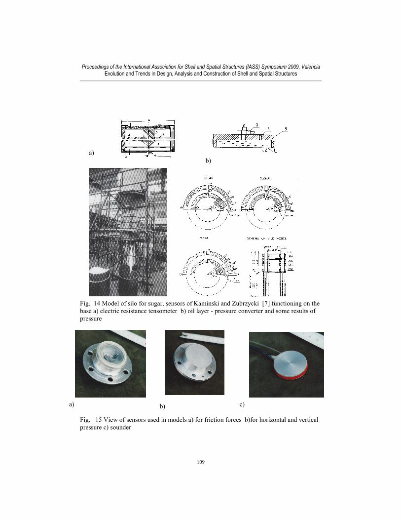
smaller sensors and sounders (5 cm in diameter, Fig. 15,16) were used on silo models. (Fig
15,17). This sensors were used in investigations of pressure in full scale silo and model silo
on rape silos with pipe elements for reduction of pressure (Fig.7,17). Some results of
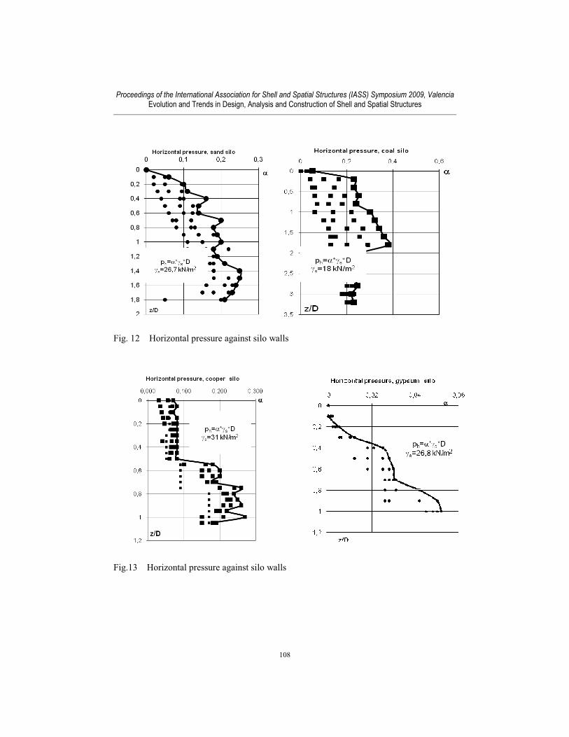
horizontal pressure ph for silos with diameter D are shown on Fig 3,10,12,13,14. They are
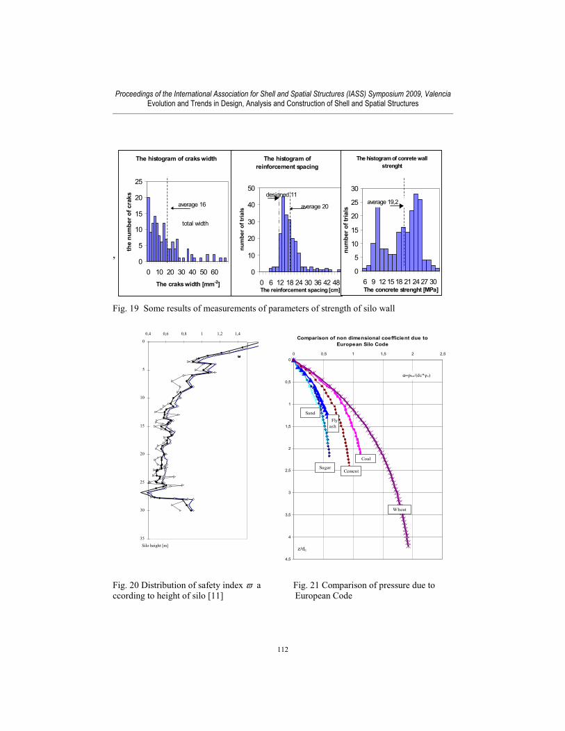
described by using non dimensional coefficient α, ph= α *γs*D, γs is specific weight.
Comparisons of coefficient α for this measured materials due European Code are presented
on Fig. 21
2. Acting loads on silo construction.The following equation must be fulfilled with regard to the reliability requirement:
SG ≤RG or Z= RG - SG ≥ 0 (1)
There are loads SG acting against silo construction (characterized by RG), such as material
pressure ph, pressure of aeration and homogenisation, temperature gradient across the silo
wall ∆T, temperature field on the silo wall caused by storage grain T, insolation and daily
temperature variation, displacement caused by, for example, shrinkage, loads caused by
post tensions, and other as concentrated loads, such as patch loadings, loads caused by
eccentricity of discharching material ets. From these loads only pressure of material ph,
temperature T and ∆T , wind loads are measurable, and only some aspects of this loads.
Strength RG of silo construction, is charakterized by such parameters as: stell and concrete,
strength, cover, diameter of bars, quantity of reinforced horizontal and vertical bars,
adhesion of bars to concrete, quality of lap splices, type and quality of wall strengthening,
openings in the silo wall, imperfections, cracks, condition of bars taking into account
corrosion, technical condition of concrete, i.e. carbonisation, etc.
3. Determination of safety for the silo structure Limit state equation (1) includes parameters of design values:
SG=Σi(tmiSxi,k) (2)
RG=Σi(γmiRxi,k) (3)
where tmi and γmi are load and resistance factors, respectively and Sxi,k Rxi,k are components
of loads and strength of silo construction, SG – denotes multi componential action effects,
that is, for example, force in horizontal reinforced bars in case of wall strength, is a function
of many parameters as: pressure, temperature gradient across the silo wall ∆T ect, RG – is
the resistance, i.e. concrete and bar strength in the case of wall strength, index “k” significa
characteristic values. In order to estimate global safety factor - it is suitable to use
characteristic parameter values Sxik and Rxik:
SG k≤ RG
k (5)
Proceedings of the International Association for Shell and Spatial Structures (IASS) Symposium 2009, Valencia Evolution and Trends in Design, Analysis and Construction of Shell and Spatial Structures
103
Fig. 1 Sensors construction based on pneumatic, dynamometer, magneto elastic
phenomena used during pressure and temperature measurements
Fig. 2 Research of silos for cement
Fig. 3 Horizontal pressure against silo walls
Proceedings of the International Association for Shell and Spatial Structures (IASS) Symposium 2009, Valencia Evolution and Trends in Design, Analysis and Construction of Shell and Spatial Structures
104
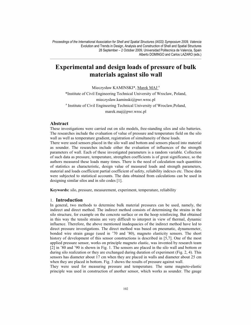
Fig. 4 Research of silo for limestone powder
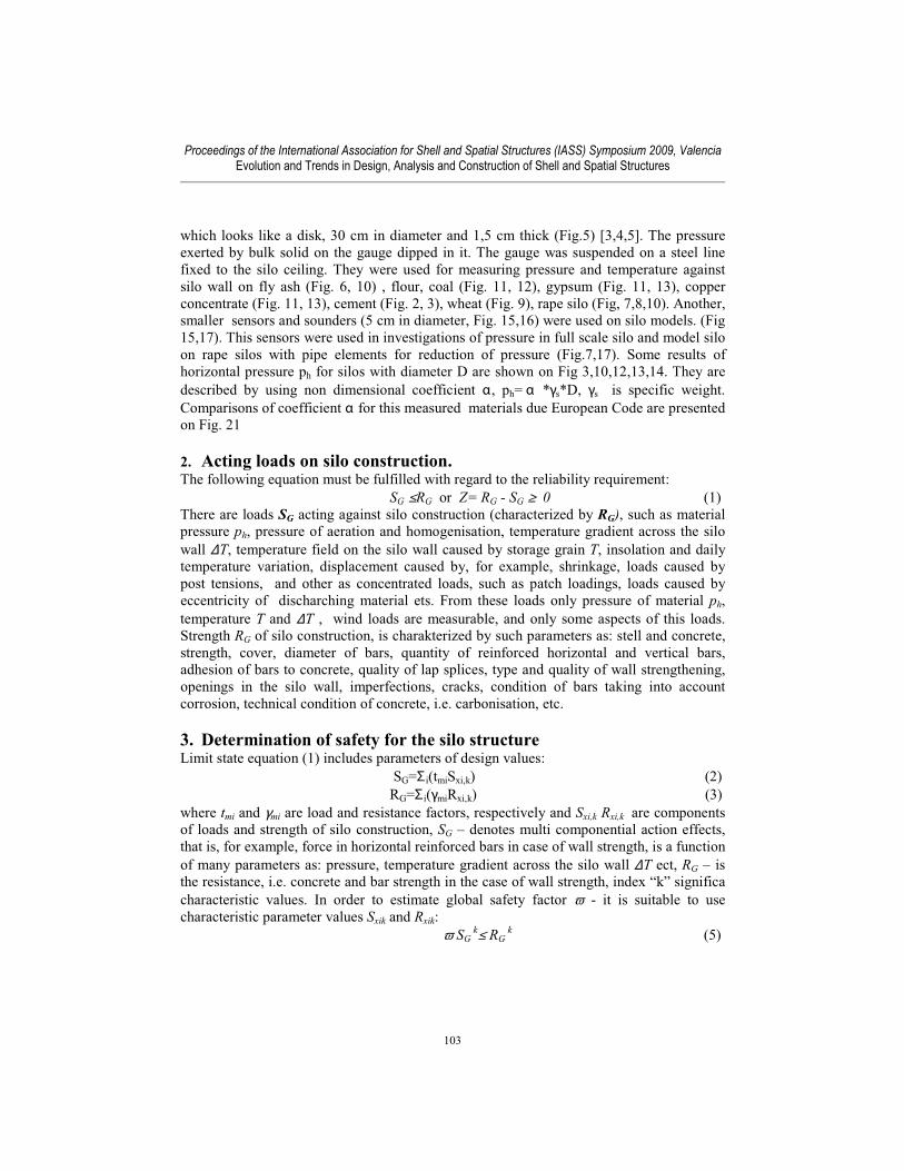
Fig. 5 Sounder sensor design by Borcz A.
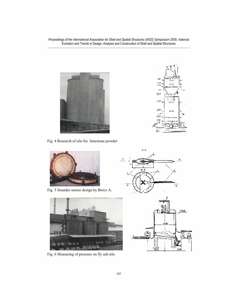
Fig. 6 Measuring of pressure on fly ash silo
Proceedings of the International Association for Shell and Spatial Structures (IASS) Symposium 2009, Valencia Evolution and Trends in Design, Analysis and Construction of Shell and Spatial Structures
105
Fig. 7 Measuring of pressure on rape concrete silo
Fig. 8 Measuring of pressure on rape ceramic silo
Fig. 9 Measuring of pressure on wheat silo
H=22 m
D=13,4 m
Proceedings of the International Association for Shell and Spatial Structures (IASS) Symposium 2009, Valencia Evolution and Trends in Design, Analysis and Construction of Shell and Spatial Structures
106
Fig. 10 Horizontal pressure against silo walls
Fig. 11 Silos for a) sand, b)gypsum, c) coal,
d) copper concentrate
c)a)
a)b)
d)
Proceedings of the International Association for Shell and Spatial Structures (IASS) Symposium 2009, Valencia Evolution and Trends in Design, Analysis and Construction of Shell and Spatial Structures
107
Fig. 12 Horizontal pressure against silo walls
Fig.13 Horizontal pressure against silo walls
Proceedings of the International Association for Shell and Spatial Structures (IASS) Symposium 2009, Valencia Evolution and Trends in Design, Analysis and Construction of Shell and Spatial Structures
108
Fig. 14 Model of silo for sugar, sensors of Kaminski and Zubrzycki [7] functioning on the
base a) electric resistance tensometer b) oil layer - pressure converter and some results of
pressure
Sensor constructiomenon
Fig. 15 View of sensors used in models a) for friction forces b)for horizontal and vertical
pressure c) sounder
a)
b)
a) b) c)
Proceedings of the International Association for Shell and Spatial Structures (IASS) Symposium 2009, Valencia Evolution and Trends in Design, Analysis and Construction of Shell and Spatial Structures
109
Fig. 16 Measurement pressure of bulk materials on silo models
Results of calculation of this coefficient for rape silo are presented on Fig. 18.
Another coefficient of construction safety [13,14,15] is described by β, the reliability
indices interval: β=zm/σz, and reliability index of risk failure pf=Φ(-β), where zm i the mean
value of function Z, σz is standard deviation of Z, Φ(-β) is Laplace function Z= RG - SG for
zm≥ β *σz construction work in safe area. Coefficient β is equal according to European
standards 3,7 ÷ 6,7, pf=10-3 ÷ 3·10
-8. Coefficient β can be separated to two βR and βS
connected with strength and loads. According to [17] there are three classes of safety
coefficients RC1, RC2, RC3 but in [15,16] we can use either RC0 class. In the last
proposal, in case typical for silo loads, where live loads are grater than dead, and when
R≤Rd; S≥Sd)=max, R and S are independent ( index d is design level). β=3,7 (pf=10-4),
βS=2,59 (pf=0,005), βR=2,96 (pf=0,0015). Some results were receivrd from investigation
on full scale silo, as rape silo [7-12]. According to [13,14,18] loads coefficients γf is equal
between 1,1 (for temperature) 1,2 ÷ 1,5 ( for pressure) but under control of material
properties range of γf is 1,2 ÷ 1,35. Coefficient of loads coincidence is 0,9. According to
[16] γf can be lower than 1,2 for RCO class. In the case of silo loads, when loads of
pressure are bigger than temperature loads and big variation of dead loads γf can be equal
1,3 for RCO class. According to [11] coefficient of loads coincidence can change from 0,8
to 0,9 for silos under acting high temperatures.
Proceedings of the International Association for Shell and Spatial Structures (IASS) Symposium 2009, Valencia Evolution and Trends in Design, Analysis and Construction of Shell and Spatial Structures
110
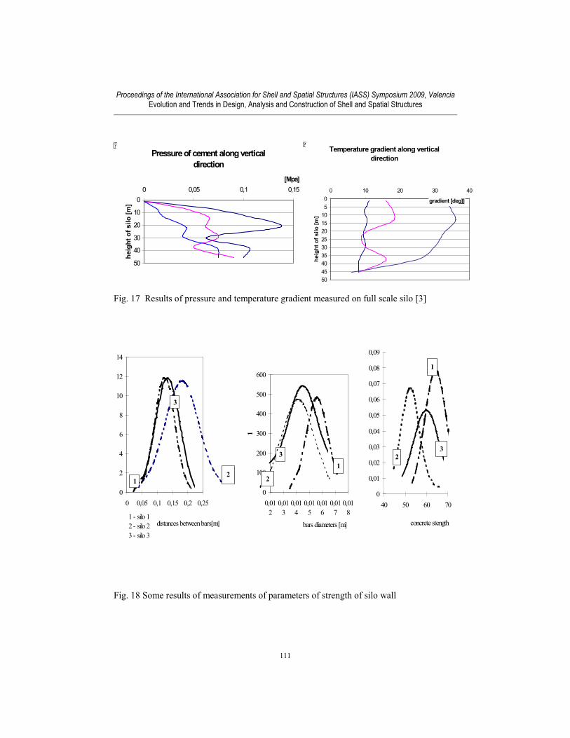
Fig. 17 Results of pressure and temperature gradient measured on full scale silo [3]
Fig. 18 Some results of measurements of parameters of strength of silo wall
Pressure of cement along vertical
direction
0
10
20
30
40
50
0 0,05 0,1 0,15
[Mpa]
he
igh
t o
f s
ilo
[m
]
Temperature gradient along vertical
direction
0
5
10
15
20
25
30
35
40
45
50
0 10 20 30 40
gradient [deg]]
he
igh
t o
f s
ilo
[m
]
0
2
4
6
8
10
12
14
0 0,05 0,1 0,15 0,2 0,25
1
1 - silo 1
2 - silo 2
3 - silo 3
distances between bars[m]
2
3
0
100
200
300
400
500
600
0,01
2
0,01
3
0,01
4
0,01
5
0,01
6
0,01
7
0,01
8
1
1
bars diameters [m]
3
2
0
0,01
0,02
0,03
0,04
0,05
0,06
0,07
0,08
0,09
40 50 60 70
1
concrete stength
2
3
Proceedings of the International Association for Shell and Spatial Structures (IASS) Symposium 2009, Valencia Evolution and Trends in Design, Analysis and Construction of Shell and Spatial Structures
111
,
Fig. 19 Some results of measurements of parameters of strength of silo wall
Fig. 20 Distribution of safety index a Fig. 21 Comparison of pressure due to
Proceedings of the International Association for Shell and Spatial Structures (IASS) Symposium 2009, Valencia Evolution and Trends in Design, Analysis and Construction of Shell and Spatial Structures
112
References
[1] PN-B-03262/2002, Silo Polish Standard, Silosy zelbetowe na materia y sypkie.
Obliczenia statyczne i projektowanie, wykonawstwo.
[2] A. Borcz, M. Maj, A. Trochanowski, Guiding principles of silo designing, construction
and operating, Prace Naukowe Instytutu Budownictwa Polit. Wroc awskiej, Wroc aw 1991,
[3] M. Maj, Wyznaczanie doswiadczalne wielkosci naporu materia ów sypkich i pola
temperatury na wybranych silosach, Politechnika Wroc awska, Wroc aw 1995,
[4] X Intern. Conf. “Reinforced and post tensioned concrete silos. ”,Kraków, 1995 Poland
[5] A. Borcz And H. A. El Rahim, Poland A New Method To Measure Pressure And
Temperature In Silos, Bulk Solids & Processing Volume 1, Number 4, November 1989
[6] M.Kaminski, M. Maj, Reliability Analysis Of The Global Safety Index Design For
Conrete Silo., The Third Israeli Conference For Conveying And Handling Of Particulate
Solids, Dead Sea, Israel, May 2000
[7] M. Kaminski, Badania Naporu Bezkohezyjnych Mat. Sypkich W Silosach, Wroc aw 86
[8] Kami ski M., Mrozowicz J., Maj M., Podolski B., Gawron K.: Zagro enia
bezpiecze stwa podczas eksploatacji baterii zblokowanych, prefabrykowanych silosów na
rzepak. XX Konferencja Naukowo-Techniczna „Awarie budowlane”. Szczecin-
Mi dzyzdroje 2001, s. 183 – 190.
[9] Instrukcja nr 366/2000 Instytutu Techniki Budowlanej „Zasady oceny bezpiecze stwa i
wzmaniania silosów elbetowych”. Warszawa 2000.
[10] Dyduch K., Kami ski M., Mrozowicz J.: Wzmocnienie silosów elbetowych poprzez
spr enie ci gnami zewn trznymi, niskotarciowymi. XVIII Konferencja Naukowo-
Techniczna „Awarie budowlane”. Szczecin-Mi dzyzdroje 1997, s. 217-244.
[11 ] M.Kaminski, M. Maj, Reliability analysis of the global safety index design for
conrete silo., The Third Israeli Conference for Conveying and Handling of Particulate
Solids, Dead Sea, Israel, May 2000
[12] Kami ski M., Mrozowicz J., Maj M., Podolski B., Wróblewski R., Gawron K.: Stan
awaryjny baterii zblokowanych silosów na nasiona oleiste. XIX Konferencja Naukowo-
Techniczna „Awarie budowlane”. Szczecin-Mi dzyzdroje 1999, s. 821 – 828.
[13]. Murzewski J., Niezawodno konstrukcji in ynierskich, Arkady, Wwa 1989
[14]. Pawlikowski J., Zró nicowanie klas niezawodno ci konstrukcji z betonu, Prace
naukowe ITB Wwa 2003
[15] Tichy M., Applied Methods of Structural Reliability, Kluver Academic Publisher,’93
Bezpiecze stwa istniej cych Konstrukcji z Betonu, Konferencje ITB Wwa Cedyna, 2004
[17] Basis of Design of Structures. Proposals for Modification of Partial Safety Factors in
Eurocodes, NKB Committee Work Reports, 1999:01 E
[18] Maj M.The Statistical Estimation Of Loads Coincidence Factor For Silo For Hot
Materials, Conference for Conveying and Handling of Particulate Solids, Budapeszt 2003
[19] M.Kaminski, M. Maj, Experimental and design loads of pressure of bulk materials
against silo wall, International Conference on Storing, Handling and transporting Bulk,
Barcelona October 2006
Proceedings of the International Association for Shell and Spatial Structures (IASS) Symposium 2009, Valencia Evolution and Trends in Design, Analysis and Construction of Shell and Spatial Structures