EXPERIMENTAL AND FINITE ELEMENT EVALUATION OF BENDING FOR GALVANIZED IRON FAKHRURRAZI B AB KARIM Report submitted in partial fulfillment of the requirements for the award of Bachelor of Mechanical Engineering Faculty of Mechanical Engineering UNIVERSITI MALAYSIA PAHANG JAN 2013
Transcript
EXPERIMENTAL AND FINITE ELEMENT EVALUATION OF BENDING FOR
GALVANIZED IRON
FAKHRURRAZI B AB KARIM
Report submitted in partial fulfillment of the requirements
for the award of Bachelor of Mechanical Engineering
Faculty of Mechanical Engineering
UNIVERSITI MALAYSIA PAHANG
JAN 2013
vi
ABSTRACT
Finite element evaluation is one of the methods in predicting the springback angle in
sheet metal bending. Predicting the springback is important since to produce the
accuracy part geometry, the design of the die and bending tool must be accurate. This
thesis aims to evaluate the reliability of finite element method by comparing the results
with experimental results. The effect of parameters such as anisotropy in springback
also has been studied. Abaqus software has been used to simulate the bending process
and the mechanical properties provided from tensile test will be used to run the
simulation. In the U-bending experiment, the die were clamped on stamping machine
and the Galvanized Iron sheets then have been bent before the springback being
measured with SolidWorks software. The results from the experiment and simulation is
slightly different for the springback angle Ɵ1 , which the simulation shows increasing
the orientation will increase the springback, and for the experimental, the springback
higher at 0 degree orientation angle, and lower at 45 degree. For the springback angle
Ɵ2 , the simulation and experimental result show that increasing the orientation angle
will increase the amount of springback. Finite element method can be used to predict
the springback since the results are nearly the same and percentages of error are below
10 %. It can be comprehended that the finite element method are suitable method to
predict the springback angle of sheet metal bending. The finite element method is
important in the future.
vii
ABSTRAK
Kaedah analisis simulasi merupakan salah satu kaedah untuk meramal pembentukan
bangkit kembali dalam pembengkokan kepingan logam. Ramalan bangkit kembali amat
penting kerana untuk menghasilkan produk yang tepat, reka bentuk alat acuan dan
peralatan pembengkokan mestilah tepat. Laporan ini bertujuan untuk menilai kebolehan
kaedah simulasi dengan membandingkan keputusan simulasi dengan keputusan
eksperimen. Kesan parameter seperti anisotropi dalam bangkit kembali juga dikaji.
Perisian Abaqus telah digunakan untuk mensimulasikan proses lenturan dan sifat-sifat
mekanik yang disediakan dalam ujian regangan akan digunakan untuk menjalankan
simulasi. Dalam eksperimen lenturan-U, alat acuan telah dikapit pada mesin tekanan
dan kepingan “ Galvanized Iron “ kemudian dibengkokan sebelum bangkit kembali
diukur dengan perisian Solidworks. Hasil daripada eksperimen dan simulasi adalah
sedikit berbeza untuk sudut bangkit kembali, Ɵ1 yang mana simulasi menunjukkan
peningkatan sudut orientasi akan meningkatkan bangkit kembali dan untuk eksperimen,
bangkit kembali lebih tinggi pada sudut orientatasi 0 darjah dan lebih rendah pada 45
darjah. Bagi sudut bangkit kembali Ɵ2 , simulasi dan hasil eksperimen menunjukkan
bahawa peningkatan sudut orientasi akan meningkatkan jumlah bangkit kembali.
Kaedah simulasi boleh digunakan untuk meramal bangkit kembali kerana corak graf
adalah hamper sama dan peratusan ralat di bawah 10 % . Dapat difahami bahawa
kaedah simulasi sesuai untuk meramal sudut bangkit kembali bagi pembengkokan
kepingan logam. Kajian lanjut mengenai parameter yang mempengaruhi proses
pembengkokan adalah penting pada masa akan datang.
viii
TABLE OF CONTENTS
Page
SUPERVISOR DECLARATION ii
STUDENT DECLARATION iii
ACKNOWLEDGEMENT v
ABSTRACT vi
ABSTRAK vii
TABLE OF CONTENTS viii
LIST OF TABLES xii
LIST OF FIGURES xiii
LIST OF SYMBOLS xv
LIST OF ABBREVIATIONS xvi
CHAPTER 1 INTRODUCTION 1
1.1 PROJECT BACKGROUND 1
1.2 PROBLEM STATEMENT 2
1.3 OBJECTIVES 2
1.4 SCOPE OF WORKS 2
CHAPTER 2 LITERATURE REVIEW 3
2.1 INTRODUCTION 3
2.2 SHEET METAL FORMING 3
2.2.1 Material Properties that affect sheet metal formability 5
ix
2.3 THEORY OF SHEET METAL BENDING 6
2.4 TYPES OF BENDING 7
2.4.1 Air Bending 7
2.4.2 Bottoming 8
2.4.3 Coining 8
2.4.4 V-bending 9
2.4.5 U- bending 10
2.5 SPRING BACK IN U – BENDING 12
2.6 GALVANIZED IRON 15
2.6.1 Material used 15
2.6.2 Material properties 15
2.6.3 The true stress–strain curve 16
CHAPTER 3 METHODOLOGY 17
3.1 INTRODUCTION 17
3.2 PROJECT FLOW CHART 18
3.3 TENSILE TEST 19
3.3.1 American Society for Testing and Materials (ASTM E8) 19
3.3.2 Specimen preparation 21
3.3.3 Tensile test experiment 25
3.4 FINITE ELEMENT 30
3.4.1 Parts modeling 31
3.4.2 Material Input 33
x
3.5 U-BENDING EXPERIMENTAL SETUP 34
3.5.1 Specimen preparation 34
3.5.2 Die 35
3.5.3 Springback measurement 36
CHAPTER 4 RESULT AND DISCUSSION 38
4.1 INTRODUCTION 38
4.2 TENSILE TEST RESULT 38
4.3 FE SIMULATION RESULTS FOR U-BENDING 42
4.3.1 Simulation of sheet metal bending 43
4.3.2 Springback measurement from solidworks 44
4.3.3 Effect of anisotropy on springback 47
4.4 U-BENDING EXPERIMENTAL RESULTS 47
4.4.1 Springback measurement using SolidWorks 2012 49
4.4.2 Effect of orientation angle on springback 52
4.5 RESULTS COMPARISON 52
CHAPTER 5 CONCLUSION 55
5.1 INTRODUCTION 55
5.2 CONCLUSION 55
5.3 RECOMMENDATIONS 56
xi
REFERENCES 57
APPENDICES 59
APPENDIX A Final Year Project 1 gantt chart 60
APPENDIX B Final Year Project 2 gantt chart 61
APPENDIX C Tensile test specimen drawing in SolidWorks 62
APPENDIX D CNC milling - G-CODE 63
xii
LIST OF TABLES
Table No. Title Page
2.1 List of correction springback on different material 14
2.2 Material properties 15
3.1 Dimension and specification of the tensile test specimen
ASTM E8 20
3.2 Total specimens preparation 21
3.3 Selected points in stress-strain diagram for 0 degree 27
3.4 Selected points in stress-strain diagram for 45 degree 28
3.5 Selected points in stress-strain diagram for 90 degree 29
3.6 Total specimens used 34
3.7 Material properties 34
4.1 Mechanical properties from tensile test result 38
4.2 10 second initial value of the data 39
4.3 Final width and length of specimen 40
4.4 Mechanical properties of galvanized iron 41
4.5 Simulation result of springback for galvanized iron 46
4.6 Experimentally measured parameters of springback 50
4.7 Springback values for experimental and simulation 52
xiii
LIST OF FIGURES
Figure No Title Page
2.1 Example of sheet metal forming 4
2.2 Air bending process 7
2.3 Bottoming process 8
2.4 Coining process 8
2.5 Illustration of V-die bending 9
2.6 Sheet metal U-bending 10
2.7 U-bending process 12
2.8 Geometry and dimensions of the piece folded 13
2.9 Correction springback based on r/e 14
2.10 Stress-strain curve 16
3.1 Project flow chart 18
3.2 Examples of rectangular (flat) tensile test specimen 20
3.3 Haas CNC milling machine 23
3.4 CNC milling machine in process 24
3.5 Specimen done from CNC machine 24
3.6 Specimen at break point 25
3.7 Stress strain graph for GI 1.0mm thickness, 90 degree rolling
direction 26
3.8 Engineering stress – strain diagram for GI, anisotropy,
R = 0 degree. 27
3.9 Engineering stress – strain diagram for GI, anisotropy,
R = 45 degree. 28
3.10 Engineering stress – strain diagram for GI, anisotropy,
R = 90 degree. 29
3.11 Blank 31
xiv
3.12 Die 31
3.13 Blank holder 32
3.14 Punch 32
3.15 Schematic and photograph for the experimental set-up 35
3.16 Parameters for springback in U-bending process 36
3.17 Specimen scanning picture 37
4.1 Different orientation angle of Stress-Strain graph for Galvanized
Iron 1.0 mm thickness 40
4.2 Geometrical description of the simulation model 42
4.3 Punch start touching the workpiece 43
4.4 During bending 43
4.5 Maximum movement of the punch 44
4.6 After bending (Punch release) 44
4.7 (a) 0 degree , (b) 45 degree , (c) 90 degree simulation of rolling
direction for Galvanized Iron 1.0mm thickness 45
4.8 Anisotropy effect on amount of springback angle ɵ1 46
4.9 Anisotropy effect on amount of springback angle ɵ2 47
4.10 Schematic description of measurement position for springback 48
4.11 (a) 2D drawing of Galvanized Iron after bending
(b) Galvanized Iron specimen after bend 48
4.12 Specimen with rolling direction 0 degree 49
4.13 Specimen with rolling direction 45 degree 49
4.14 Specimen with rolling direction 90 degree 50
4.15 Effect of orientation angle on springback, ɵ1 51
4.16 Effect of orientation angle on springback, ɵ2 51
4.17 Comparison between simulation and experimental for ɵ1 53
4.18 Comparison between simulation and experimental for ɵ2 53
xv
LIST OF SYMBOLS
σ2 Variance
Fmax Bending Force
μ Mean
∆ϴ /ϴ Spring back ratio
n Strain hardening exponent
R Normal anisotropic value
v Poisson’s ratio
E Young’s modulus
t Sheet thickness
ρ Neutral axis
∆ϴ Springback angle
I Inertia moment of cross-section per unit width
M(α) Bending moment along the bending surface
Rn Neutral layer radius of the sheet
K Ultimate tensile strength
w Die gap
t Sheet thickness
∆K Spring back curvature
M Bending moment
L Inertia moment of cross-section
xvi
LIST OF ABBREVIATIONS
AISI American Iron and Steel Institute
ASTM American Society for Testing and Material
TRIP Transformation Induced Plasticity
CNC Computer Numerical Control
UTS Ultimate Tensile Strength
FEA Finite Element Analysis
CRES Called-Corrosion-Resistant
1
CHAPTER 1
INTRODUCTION
1.1 PROJECT BACKGROUND
Springback commonly happens in manufacturing industries especially in the
automobile and aircraft industries. It is occur when existing plasticity in sheet metal.
One of the experiments to determine the process is bending process. Bending of sheet
metal is one of the widely used processes in manufacturing industries especially in the
automobile and aircraft industries. This bending operation is about shaping of sheet
metal by straining the metal around a straight axis. A bending operation compresses the
interior side of the bend and stretches the exterior side. Bending is most common
operations to change the shape of a material by plastically deforming it and depends
primarily on the materials type, strength, thickness and part complexity.
Springback is an issue in sheet metal forming processes. The springback is a
principle problem when precise components are produced. Elastic energy stored in sheet
metal in bending operation is released during unloading and the sheet metal tends to
return to its initial state. Thus the dimensions and the shape of component are changed.
Basically, this project deals with experimental and finite element evaluation of
bending for galvanic iron. In this project, bending analysis will take spring back as one
of the part of bending analysis.
Through this project, bending analysis can be made in term of knowing about
springback of galvanic iron material. Many factors affect springback such as types of
material, types of bending, and thickness of material and sheet anisotropy.
2
1.2 PROBLEM STATEMENT
Bending is a process in which a sheet metal is plastically deformed to a curve by
predicting the precision in angle. When the material has a tendency to partially return to
its original shape because of the elastic recovery of the material, it is called springback.
The springback is generally defined as the additional deformation of sheet metal parts
after the loading is removed and the influenced factor not only by the tensile and yield
strengths, but also by thickness, bend radius and bend angle. Springback is a
phenomenon of elastic nature determined by the distribution of stress on the section of
the form part. In the manufacturing industry, it is still a practical problem to predict the
final geometry of the part after springback and to design the appropriate tooling in order
to compensate for springback.
1.3 OBJECTIVES
1. To determine the springback angle in sheet metal bending for Galvanized Iron.
2. To determine the influence of anisotropy,R on springback.
3. To determine reliability of Finite Element Method (FEA) in sheet metal by
comparing with the experimental results.
1.4 SCOPE OF WORKS
1. To study the basic understanding of springback behaviour from the past
researchers (Literature Review).
2. To conduct experiments of tensile test to determine mechanical properties of
Galvanized Iron.
3. To perform Finite Element Evaluation analysis of bending for Galvanized Iron.
4. To conduct experiments of sheet metal bending.
5. To analyze and compare the simulation and experimental result.
3
CHAPTER 2
LITERATURE REVIEW
2.1 INTRODUCTION
This chapter will discuss about theory of bending, types of bending, materials
and parameters involved that causing the bending. This chapter will have all necessary
information from journal, book and articles that are related to this project and also about
the springback study. The sources for the literature review are library books, journal
from established databases such as Science Direct and Scopus, article and also
newspaper article.
2.2 SHEET METAL FORMING
Sheet metal forming processes are those in which force is applied to a piece of
sheet metal to modify its geometry rather than remove any material. The applied force
stresses the metal beyond its yield strength, causing the material to plastically deform,
but not to fail. By doing so, the sheet can be bent or stretched into a variety of complex
shapes. There are a few examples of common sheet metal forming such as blanking and
piercing, bending, stretching, stamping or draw die forming, coining and ironing, as
shown in figure 2.1 (Z. Marciniak, 2002).
4
(a) (b)
(c) (d)
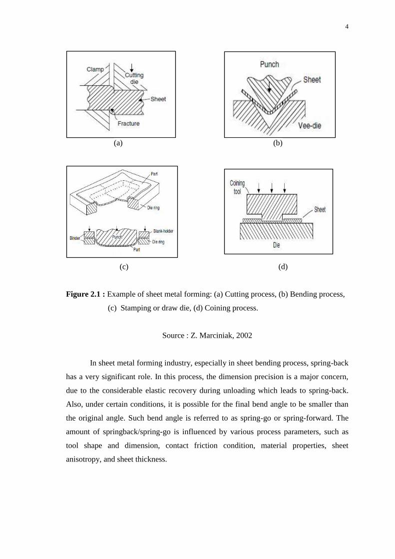
Figure 2.1 : Example of sheet metal forming: (a) Cutting process, (b) Bending process,
(c) Stamping or draw die, (d) Coining process.
Source : Z. Marciniak, 2002
In sheet metal forming industry, especially in sheet bending process, spring-back
has a very significant role. In this process, the dimension precision is a major concern,
due to the considerable elastic recovery during unloading which leads to spring-back.
Also, under certain conditions, it is possible for the final bend angle to be smaller than
the original angle. Such bend angle is referred to as spring-go or spring-forward. The
amount of springback/spring-go is influenced by various process parameters, such as
tool shape and dimension, contact friction condition, material properties, sheet
anisotropy, and sheet thickness.
5
2.2.1 Material Properties that affect Sheet Metal Formability
a) Ductility: Metal used in the sheet metal work must be ductile. If we use a brittle
metal it can easily undergo failure during forming. That’s why metal’s ductility
is very important in sheet metal working.
b) Yield strength: Yield strength of a material used in sheet metal forming must be
low. High strength metals have reduced stretch distribution characteristic,
making them less stretchable and drawable than lower strength metals. Stretch
distributions characteristic determine the steel ability to distribute stretch over a
large surface area.
c) Elastic modulus: Stretch distribution affects not only stretch ability, but also
elastic recovery, or spring back, and the metal’s total elongation.
d) Discontinuously Yielding: Low carbon show a discontinuous yielding
accompanied with the formation of Lǖder bands, which reduces the surface
quality of the end product. In order to remove the discontinuous yield point a
temper rolling can be applied.
e) Work Hardening Rate (n): Work hardening rate is a very important sheet metal
forming parameters. When increases material’s resistance to necking also
increase. The work hardening is the mechanism, which prevents local yielding
and increase the uniform elongation.
f) Anisotropy (Directionality): Anisotropy is another factor that affects
formability. Once consequence of directionality is a change in mechanical
properties with direction. When forming sheet metal, practical consequences of
directionality include such phenomena as excess wrinkling, puckering, ear-
formation, local thinning, or actual rupture.
6
2.3 THEORY OF SHEET METAL BENDING
Bending can be defined as shaping materials without removing any chips around
a definite axis through or without heat. Bending is the process of placing a sheet of
metal over the matrix on the press bed where the sheet is bent around the tip of the
punch as it enters the die. Bending dies are the setup, proper to the required piece shape,
consisting of a female die and punch, and making permanent changes on steel sheet
material. (Özgür Tekaslan et. al. 2008)
Bending along a straight line is the most common of all sheet forming processes.
It can be done in various ways such as forming along the complete bend in a die, or by
wiping, folding or flanging in special machines, or sliding the sheet over a radius in a
die. A very large amount of sheet is roll formed where it is bent progressively under
shaped rolls. Failure by splitting during a bending process is usually limited to high-
strength, less ductile sheet and a more common cause of unsatisfactory bending is lack
of dimensional control in terms of springback and thinning. A few among the most
common applications of sheet metal parts are as automobile and aircraft panels,
housings and cabinets. Customization of sheet metal parts to produce parts of varying
configurations and sizes is a very common occurrence in a sheet metal fabrication
scenario. (Olaf Diegel, 2002)
7
2.4 TYPES OF BENDING
There are several types of bending that commonly used in the industries such as
air bending, bottoming, coining, V- bending, and U-bending. A bending tool must be
decided depending on the shape and severity of bend.
2.4.1 Air Bending
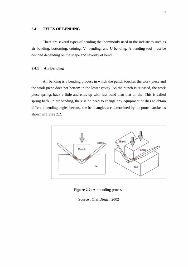
Air bending is a bending process in which the punch touches the work piece and
the work piece does not bottom in the lower cavity. As the punch is released, the work
piece springs back a little and ends up with less bend than that on the. This is called
spring back. In air bending, there is no need to change any equipment or dies to obtain
different bending angles because the bend angles are determined by the punch stroke, as
shown in figure 2.2.
Figure 2.2: Air bending process
Source : Olaf Diegel, 2002
8
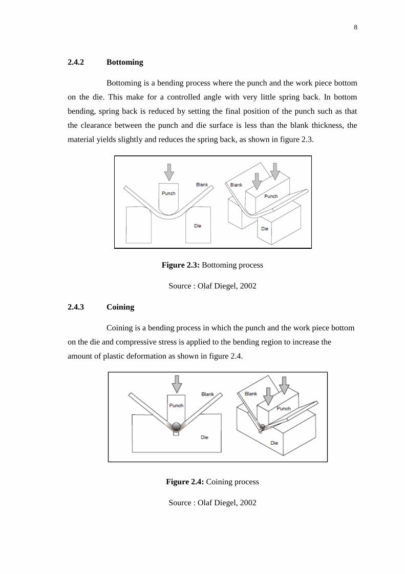
2.4.2 Bottoming
Bottoming is a bending process where the punch and the work piece bottom
on the die. This make for a controlled angle with very little spring back. In bottom
bending, spring back is reduced by setting the final position of the punch such as that
the clearance between the punch and die surface is less than the blank thickness, the
material yields slightly and reduces the spring back, as shown in figure 2.3.
Figure 2.3: Bottoming process
Source : Olaf Diegel, 2002
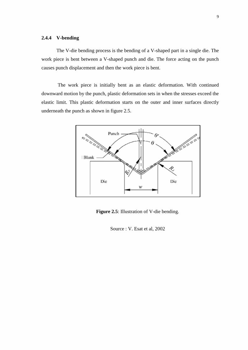
2.4.3 Coining
Coining is a bending process in which the punch and the work piece bottom
on the die and compressive stress is applied to the bending region to increase the
amount of plastic deformation as shown in figure 2.4.
Figure 2.4: Coining process
Source : Olaf Diegel, 2002
9
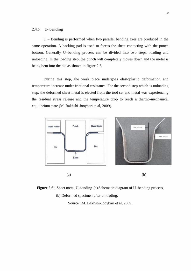
2.4.4 V-bending
The V-die bending process is the bending of a V-shaped part in a single die. The
work piece is bent between a V-shaped punch and die. The force acting on the punch
causes punch displacement and then the work piece is bent.
The work piece is initially bent as an elastic deformation. With continued
downward motion by the punch, plastic deformation sets in when the stresses exceed the
elastic limit. This plastic deformation starts on the outer and inner surfaces directly
underneath the punch as shown in figure 2.5.
Figure 2.5: Illustration of V-die bending.
Source : V. Esat et al, 2002
10
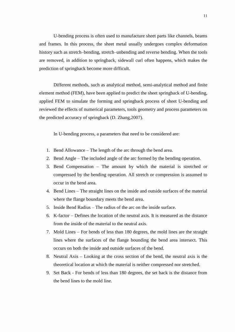
2.4.5 U- bending
U – Bending is performed when two parallel bending axes are produced in the
same operation. A backing pad is used to forces the sheet contacting with the punch
bottom. Generally U–bending process can be divided into two steps, loading and
unloading. In the loading step, the punch will completely moves down and the metal is
being bent into the die as shown in figure 2.6.
During this step, the work piece undergoes elastoplastic deformation and
temperature increase under frictional resistance. For the second step which is unloading
step, the deformed sheet metal is ejected from the tool set and metal was experiencing
the residual stress release and the temperature drop to reach a thermo-mechanical
equilibrium state (M. Bakhshi-Jooybari et al, 2009).
(a) (b)
Figure 2.6: Sheet metal U-bending: (a) Schematic diagram of U–bending process,
(b) Deformed specimen after unloading.
Source : M. Bakhshi-Jooybari et al, 2009.
11
U-bending process is often used to manufacture sheet parts like channels, beams
and frames. In this process, the sheet metal usually undergoes complex deformation
history such as stretch–bending, stretch–unbending and reverse bending. When the tools
are removed, in addition to springback, sidewall curl often happens, which makes the
prediction of springback become more difficult.
Different methods, such as analytical method, semi-analytical method and finite
element method (FEM), have been applied to predict the sheet springback of U-bending,
applied FEM to simulate the forming and springback process of sheet U-bending and
reviewed the effects of numerical parameters, tools geometry and process parameters on
the predicted accuracy of springback (D. Zhang,2007).
In U-bending process, a parameters that need to be considered are:
1. Bend Allowance – The length of the arc through the bend area.
2. Bend Angle – The included angle of the arc formed by the bending operation.
3. Bend Compensation – The amount by which the material is stretched or
compressed by the bending operation. All stretch or compression is assumed to
occur in the bend area.
4. Bend Lines – The straight lines on the inside and outside surfaces of the material
where the flange boundary meets the bend area.
5. Inside Bend Radius – The radius of the arc on the inside surface.
6. K-factor – Defines the location of the neutral axis. It is measured as the distance
from the inside of the material to the neutral axis.
7. Mold Lines – For bends of less than 180 degrees, the mold lines are the straight
lines where the surfaces of the flange bounding the bend area intersect. This
occurs on both the inside and outside surfaces of the bend.
8. Neutral Axis – Looking at the cross section of the bend, the neutral axis is the
theoretical location at which the material is neither compressed nor stretched.
9. Set Back - For bends of less than 180 degrees, the set back is the distance from
the bend lines to the mold line.
12
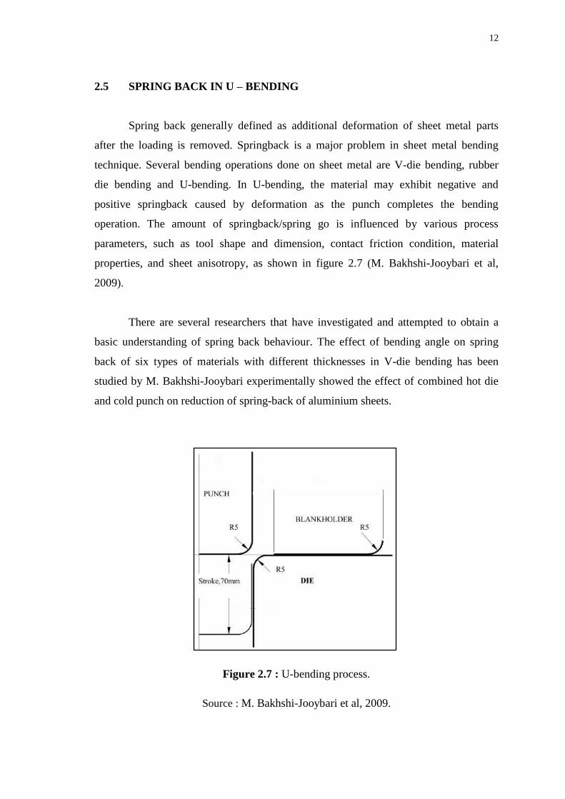
2.5 SPRING BACK IN U – BENDING
Spring back generally defined as additional deformation of sheet metal parts
after the loading is removed. Springback is a major problem in sheet metal bending
technique. Several bending operations done on sheet metal are V-die bending, rubber
die bending and U-bending. In U-bending, the material may exhibit negative and
positive springback caused by deformation as the punch completes the bending
operation. The amount of springback/spring go is influenced by various process
parameters, such as tool shape and dimension, contact friction condition, material
properties, and sheet anisotropy, as shown in figure 2.7 (M. Bakhshi-Jooybari et al,
2009).
There are several researchers that have investigated and attempted to obtain a
basic understanding of spring back behaviour. The effect of bending angle on spring
back of six types of materials with different thicknesses in V-die bending has been
studied by M. Bakhshi-Jooybari experimentally showed the effect of combined hot die
and cold punch on reduction of spring-back of aluminium sheets.