David L. Krause Glenn Research Center, Cleveland, Ohio Sreeramesh Kalluri Ohio Aerospace Institute, Brook Park, Ohio Ashwin R. Shah and Igor Korovaichuk Sest, Inc., Middleburg Heights, Ohio Experimental Creep Life Assessment for the Advanced Stirling Convertor Heater Head NASA/TM—2010-216814 October 2010 AIAA–2010–7093
Transcript
David L. KrauseGlenn Research Center, Cleveland, Ohio
Sreeramesh KalluriOhio Aerospace Institute, Brook Park, Ohio
Ashwin R. Shah and Igor KorovaichukSest, Inc., Middleburg Heights, Ohio
Experimental Creep Life Assessment for theAdvanced Stirling Convertor Heater Head
NASA/TM—2010-216814
October 2010
AIAA–2010–7093
NASA STI Program . . . in Profi le
Since its founding, NASA has been dedicated to the advancement of aeronautics and space science. The NASA Scientifi c and Technical Information (STI) program plays a key part in helping NASA maintain this important role.
The NASA STI Program operates under the auspices of the Agency Chief Information Offi cer. It collects, organizes, provides for archiving, and disseminates NASA’s STI. The NASA STI program provides access to the NASA Aeronautics and Space Database and its public interface, the NASA Technical Reports Server, thus providing one of the largest collections of aeronautical and space science STI in the world. Results are published in both non-NASA channels and by NASA in the NASA STI Report Series, which includes the following report types: • TECHNICAL PUBLICATION. Reports of
completed research or a major signifi cant phase of research that present the results of NASA programs and include extensive data or theoretical analysis. Includes compilations of signifi cant scientifi c and technical data and information deemed to be of continuing reference value. NASA counterpart of peer-reviewed formal professional papers but has less stringent limitations on manuscript length and extent of graphic presentations.
• TECHNICAL MEMORANDUM. Scientifi c
and technical fi ndings that are preliminary or of specialized interest, e.g., quick release reports, working papers, and bibliographies that contain minimal annotation. Does not contain extensive analysis.
• CONTRACTOR REPORT. Scientifi c and
technical fi ndings by NASA-sponsored contractors and grantees.
• CONFERENCE PUBLICATION. Collected papers from scientifi c and technical conferences, symposia, seminars, or other meetings sponsored or cosponsored by NASA.
• SPECIAL PUBLICATION. Scientifi c,
technical, or historical information from NASA programs, projects, and missions, often concerned with subjects having substantial public interest.
• TECHNICAL TRANSLATION. English-
language translations of foreign scientifi c and technical material pertinent to NASA’s mission.
Specialized services also include creating custom thesauri, building customized databases, organizing and publishing research results.
For more information about the NASA STI program, see the following:
• Access the NASA STI program home page at http://www.sti.nasa.gov
• E-mail your question via the Internet to help@
sti.nasa.gov • Fax your question to the NASA STI Help Desk
at 443–757–5803 • Telephone the NASA STI Help Desk at 443–757–5802 • Write to:
NASA Center for AeroSpace Information (CASI) 7115 Standard Drive Hanover, MD 21076–1320
David L. KrauseGlenn Research Center, Cleveland, Ohio
Sreeramesh KalluriOhio Aerospace Institute, Brook Park, Ohio
Ashwin R. Shah and Igor KorovaichukSest, Inc., Middleburg Heights, Ohio
Experimental Creep Life Assessment for theAdvanced Stirling Convertor Heater Head
NASA/TM—2010-216814
October 2010
AIAA–2010–7093
National Aeronautics andSpace Administration
Glenn Research CenterCleveland, Ohio 44135
Prepared for theEight International Energy Conversion Engineering Conference (IECEC)sponsored by the American Institute of Aeronautics and AstronauticsNashville, Tennessee, July 25–28, 2010
Acknowledgments
The authors appreciate and thank the inspiring leadership and program management at Glenn Research Center provided by Dick Shaltens,Jeff Schreiber, Wayne Wong, Lanny Thieme, and Geoff Bruder, as well as the full support and technical management ofDrs. Ajay Misra, Steven Arnold, and Michael Nathal. The authors also thank Dr. Randy Bowman for his expert advice and continued support in required metallurgy developments and investigations, Ralph Pawlik and Frank Bremenour for their benefi cial test engineering, technical collaboration, and able laboratory support for heater head benchmark testing, and Ethan Brewer of The Ohio State University for his enthusiastic developments in experimental methods and analysis techniques. The Science Mission Directorate at NASA Headquarters provided funding to complete the work described herein, and the authors truly are grateful for that enduring commitment.
Available from
NASA Center for Aerospace Information7115 Standard DriveHanover, MD 21076–1320
National Technical Information Service5301 Shawnee Road
Alexandria, VA 22312
Available electronically at http://gltrs.grc.nasa.gov
Trade names and trademarks are used in this report for identifi cation only. Their usage does not constitute an offi cial endorsement, either expressed or implied, by the National Aeronautics and
Space Administration.
Level of Review: This material has been technically reviewed by technical management.
This report contains preliminary fi ndings, subject to revision as analysis proceeds.
NASA/TM—2010-216814 1
Experimental Creep Life Assessment for the Advanced Stirling Convertor Heater Head
David L. Krause
National Aeronautics and Space Administration Glenn Research Center Cleveland, Ohio 44135
Sreeramesh Kalluri
Ohio Aerospace Institute Brook Park, Ohio 44142
Ashwin R. Shah and Igor Korovaichuk
Sest, Inc. Middleburg Heights, Ohio 44130
Abstract
The United States Department of Energy is planning to develop the Advanced Stirling Radioisotope Generator (ASRG) for the National Aeronautics and Space Administration (NASA) for potential use on future space missions. The ASRG provides substantial efficiency and specific power improvements over radioisotope power systems of heritage designs. The ASRG would use General Purpose Heat Source modules as energy sources and the free-piston Advanced Stirling Convertor (ASC) to convert heat into electrical energy. Lockheed Martin Corporation of Valley Forge, Pennsylvania, is integrating the ASRG systems, and Sunpower, Inc., of Athens, Ohio, is designing and building the ASC. NASA Glenn Research Center of Cleveland, Ohio, manages the Sunpower contract and provides technology development in several areas for the ASC. One area is reliability assessment for the ASC heater head, a critical pressure vessel within which heat is converted into mechanical oscillation of a displacer piston. For high system efficiency, the ASC heater head operates at very high temperature (850 °C) and therefore is fabricated from an advanced heat-resistant nickel-based superalloy Microcast MarM-247. Since use of MarM-247 in a thin-walled pressure vessel is atypical, much effort is required to assure that the system will operate reliably for its design life of 17 years. One life-limiting structural response for this application is creep; creep deformation is the accumulation of time-dependent inelastic strain under sustained loading over time. If allowed to progress, the deformation eventually results in creep rupture. Since creep material properties are not available in the open literature, a detailed creep life assessment of the ASC heater head effort is underway. This paper presents an overview of that creep life assessment approach, including the reliability-based creep criteria developed from coupon testing, and the associated heater head deterministic and probabilistic analyses. The approach also includes direct “benchmark” experimental creep assessment. This element provides high-fidelity creep testing of prototypical heater head test articles to investigate the relevant material issues and multiaxial stress state. Benchmark testing provides required data to evaluate the complex life assessment methodology and to validate that analysis. Results from current benchmark heater head tests and newly developed experimental methods are presented. In the concluding remarks, the test results are shown to compare favorably with the creep strain predictions and are the first experimental evidence for a robust ASC heater head creep life.
Introduction
The United States Department of Energy (DOE) is planning to develop the Advanced Stirling Radioisotope Generator (ASRG) for the National Aeronautics and Space Administration (NASA) for potential use on future science missions, such as lunar applications, Mars rovers, and deep space missions. The ASRG would use General Purpose Heat Source (GPHS) modules as energy sources and Stirling free-piston convertors to convert the heat into mechanical energy and then into electrical energy. The ASRG provides substantial efficiency and specific power improvements over radioisotope power systems of heritage designs. Lockheed Martin Corporation of Valley Forge, Pennsylvania, is the ASRG systems integrator, under contract to DOE (Ref. 1). The current ASRG configuration uses the free-piston Advanced Stirling Convertor (ASC) designed by Sunpower, Inc. of Athens, Ohio (Ref. 2).
NASA/TM—2010-216814 2
Sunpower is developing the ASC under a NASA Research Announcement award from NASA Glenn Research Center (GRC) of Cleveland, Ohio. GRC also provides technology development in several areas for the ASC (Refs. 3 and 4).
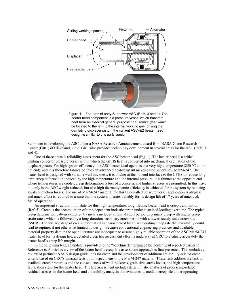
One of these areas is reliability assessment for the ASC heater head (Fig. 1). The heater head is a critical Stirling convertor pressure vessel within which the GPHS heat is converted into mechanical oscillation of the displacer piston. For high system efficiency, the ASC heater head operates at a very high temperature (850 °C at the hot end), and it is therefore fabricated from an advanced heat-resistant nickel-based superalloy, MarM-247. The heater head is designed with variable wall thickness; it is thicker at the hot end interface to the GPHS to reduce long-term creep deformation induced by the high temperature and the internal pressure. It is thinner at the opposite end where temperatures are cooler, creep deformation is less of a concern, and higher stresses are permitted. In this way, not only is the ASC weight reduced, but also high thermodynamic efficiency is achieved for the system by reducing axial conduction losses. The use of MarM-247 material for this thin-walled pressure vessel application is atypical, and much effort is required to assure that the system operates reliably for its design life of 17 years of untended, fueled operation.
An important structural limit state for this high-temperature, long lifetime heater head is creep deformation (Ref. 5). Creep is the accumulation of time-dependent inelastic strain under sustained loading over time. The typical creep deformation pattern exhibited by metals includes an initial short period of primary creep with higher creep strain rates, which is followed by a long-duration secondary creep period with a lower, steady-state creep rate (SSCR). The tertiary stage of creep deformation is characterized by an accelerating creep rate that eventually could lead to rupture, if not otherwise limited by design. Because conventional engineering practices and available material property data in the open literature are inadequate to assure highly reliable operation of the ASC MarM-247 heater head for its design life, a detailed creep life assessment effort is underway at GRC to evaluate accurately the heater head’s creep life margin.
In the following text, an update is provided to the “benchmark” testing of the heater head reported earlier in Reference 6. A brief overview of the heater head’s creep life assessment approach is first presented. This includes a review of pertinent NASA design guidelines for creep and the development of additional reliability-related creep criteria based on GRC’s uniaxial tests of thin specimens of the MarM-247 material. These tests address the lack of available creep properties and the consequences of wall thickness, grain size, stress levels, and high-temperature fabrication steps for the heater head. The life assessment includes deterministic analysis of processing-related residual stresses in the heater head and a durability analysis that evaluates its median creep life under operating
NASA/TM—2010-216814 3
conditions. The life assessment also includes probabilistic reliability analysis, which evaluates the heater head reliability dependent on uncertainties in wall thickness due to manufacturing variations, in the working gas pressure due to measurement and control, and in the creep properties of the material itself based on the GRC creep test results (Ref. 7).
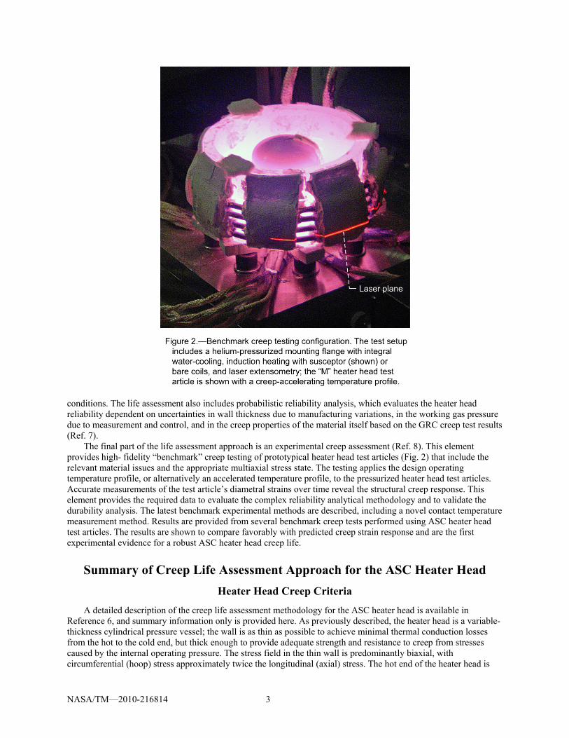
The final part of the life assessment approach is an experimental creep assessment (Ref. 8). This element provides high- fidelity “benchmark” creep testing of prototypical heater head test articles (Fig. 2) that include the relevant material issues and the appropriate multiaxial stress state. The testing applies the design operating temperature profile, or alternatively an accelerated temperature profile, to the pressurized heater head test articles. Accurate measurements of the test article’s diametral strains over time reveal the structural creep response. This element provides the required data to evaluate the complex reliability analytical methodology and to validate the durability analysis. The latest benchmark experimental methods are described, including a novel contact temperature measurement method. Results are provided from several benchmark creep tests performed using ASC heater head test articles. The results are shown to compare favorably with predicted creep strain response and are the first experimental evidence for a robust ASC heater head creep life.
Summary of Creep Life Assessment Approach for the ASC Heater Head
Heater Head Creep Criteria
A detailed description of the creep life assessment methodology for the ASC heater head is available in Reference 6, and summary information only is provided here. As previously described, the heater head is a variable-thickness cylindrical pressure vessel; the wall is as thin as possible to achieve minimal thermal conduction losses from the hot to the cold end, but thick enough to provide adequate strength and resistance to creep from stresses caused by the internal operating pressure. The stress field in the thin wall is predominantly biaxial, with circumferential (hoop) stress approximately twice the longitudinal (axial) stress. The hot end of the heater head is
NASA/TM—2010-216814 4
thick, because the material strength and creep resistance are relatively low at the elevated temperatures; the wall thickness tapers to be very thin at the cold end, where the material strength and creep resistance are higher.
A review of NASA requirements for creep revealed that design guidance for structures is limited. The pertinent technical standard for spaceflight hardware (Ref. 9) recommends maintaining a minimum service life factor of 4.0 on creep life for “well-characterized materials.” Unfortunately, adequate characterization of the MarM-247 material of construction is not available publicly, and this led to the development of the following reliability-based creep criteria. The criteria provide high assurance that heater head creep remains in the easily predictable secondary creep regime while allowing localized stress redistribution without leading to creep rupture. The criteria are based on analysis of results from a series of GRC uniaxial creep tests performed on thin “master heat” Microcast MarM-247 coupon specimens at a range of temperatures and stresses. By extracting specimens from production-processed heater head castings, metallurgical chemistry and grain microstructural effects on creep properties are assured to be captured; by designing the creep specimens with thicknesses similar to the heater head walls, potential thin-wall consequences on creep deformation also are captured.
Specifically, analyses must demonstrate with a minimum reliability level of 0.999 that the following three criteria are met throughout the heater head: 1) the through-thickness average creep strain must not be greater than the average creep strain at the onset of tertiary creep observed in the uniaxial GRC tests; 2) the peak localized creep strains must not be greater than 70 percent of the minimum observed creep failure strain in any uniaxial GRC test; and, 3) the average time to through-thickness onset of tertiary creep must not be less than the lower of 70 percent of the time to rupture, or the time to onset of tertiary creep based on the uniaxial GRC tests.
Heater Head Creep Life Assessment Methodology
Heater head creep life assessment is a four-step approach. The first step is to determine experimentally the creep strains and times to the onset of tertiary creep, and the creep strains and times to rupture, for the GRC uniaxial creep tests over a range of temperatures and stresses as described in the preceding paragraphs. The second step is to complete a deterministic durability analysis of the heater head for its residual stress state, operating conditions, and design life of 17 years; this time-domain nonlinear analysis uses a GRC-developed master-curve material creep model (Ref. 7) to calculate the heater head median creep response. The third step of the life assessment approach is a probabilistic analysis (Ref. 7) to evaluate uncertainties in a) the GRC uniaxial creep test data, b) the design parameters, and c) the operating conditions of the heater head, to determine if the three creep criteria are met with a minimum reliability level of 0.999.
The fourth step of the approach is validation of the complex methodology with benchmark creep testing of heater head test articles. Within this final step, heater head test articles are placed under either accelerated or prototypical temperature and stress conditions. Accelerated benchmark testing is performed to provide early test results for the ASC project, whereas prototypical testing is performed to evaluate the ASC heater head design operating conditions. Because the test article’s stress state is induced by internal pressure, a biaxial stress state similar to that in the ASC heater head assembly is obtained. In addition, any consequences to creep properties due to material grain microstructure, heater head thin walls, or potentially inhomogeneous heat treatment during fabrication, are investigated. For this step, the benchmark test results are compared to predicted creep strains for the experimental conditions. Using the procedures outlined above for the second and third steps, the heater head creep life assessment methodology is determined to be valid if the measured cumulative creep strains fall within a three-sigma range of the calculated median value, indicating approximately 0.999 reliability, for the experimental temperature, pressure, and strain measurement uncertainties. If the cumulative creep strains fall out of the three sigma range, then the methodology would be reviewed and modified to more accurately model the experimental setup and uncertainties. Any required systemic changes also would be incorporated into the heater head life assessment methodology.
Heater Head Benchmark Creep Testing
The remainder of this manuscript presents further information about the fourth step for heater head creep life assessment, that is, benchmark creep testing of heater head test articles. Included are developments in experimental methods, findings from four benchmark creep tests, and conclusions drawn from the results.
NASA/TM—2010-216814 5
Developments in Experimental Methods for Benchmark Creep Testing
Based on early test experiences, new developments were incorporated in the most recent benchmark creep tests to improve the measurement of creep strains and to minimize the possibility of undesirable fatigue cracks in the MarM-247 heater head test articles.
Oxidation Layer Growth Study
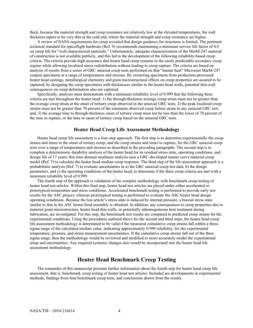
Test methods were developed and experimental results were produced for an oxidation layer growth study on the Microcast MarM-247 superalloy used for heater head benchmark creep test articles. Because the benchmark creep testing is performed at high temperature and in air, the test articles are subjected to an oxidizing environment (which is not present in the proposed ASC operating environment), causing the exterior test article surfaces to oxidize slightly. The thickness and the growth of this oxidation layer with time must be taken into account to accurately calculate the heater head creep strains using the benchmark creep test methodology, which relies on optical laser measurements of the test article’s outside diameter (Fig. 3).
Based on the availability of previously machined beam specimens, two Microcast MarM-247 and one large-grain MarM-247 rectangular specimens were used for the oxidation layer growth study. The specimens were exposed to an 850 °C air environment in a metallurgical tube furnace, and removed at various time increments to be dimensionally measured, weighed, and photographed. In addition, one large-grain MarM-247 specimen was held at ambient conditions for the test duration and served as a measurement control specimen. The specimen dimensions were nominally 5 by 3 by 36 mm.
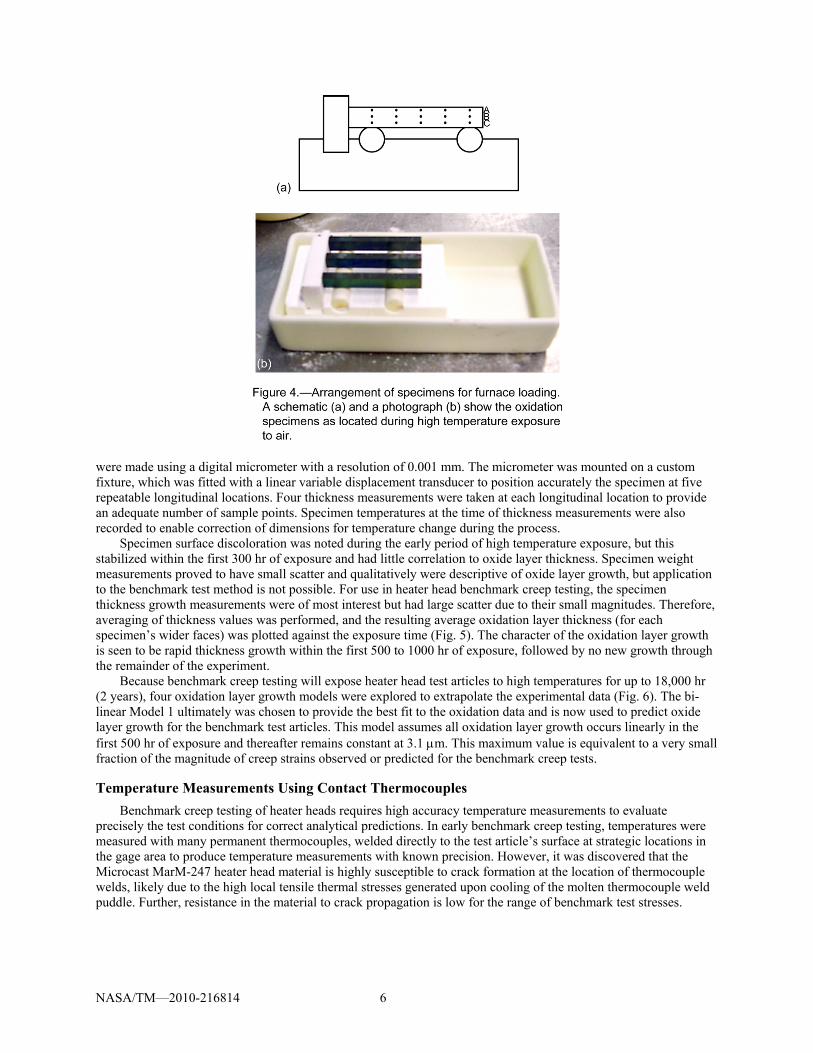
The high temperature exposures were conducted in a Lindberg Model 54433 tube furnace with a front tube port of approximately 6.5 mm diameter left open to permit room air to exchange with furnace air. In this way, the benchmark creep test air exposure was approximately duplicated. The specimens were located on alumina rollers in an alumina crucible tray and placed in identical positions for each heat soak (Fig. 4). Precise specimen measurements were recorded at 10 exposure times during the test duration of 5036 hr; thickness measurements
NASA/TM—2010-216814 6
were made using a digital micrometer with a resolution of 0.001 mm. The micrometer was mounted on a custom fixture, which was fitted with a linear variable displacement transducer to position accurately the specimen at five repeatable longitudinal locations. Four thickness measurements were taken at each longitudinal location to provide an adequate number of sample points. Specimen temperatures at the time of thickness measurements were also recorded to enable correction of dimensions for temperature change during the process.
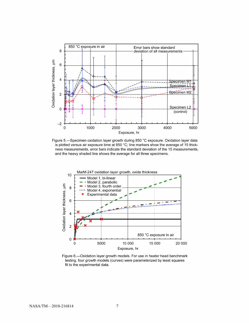
Specimen surface discoloration was noted during the early period of high temperature exposure, but this stabilized within the first 300 hr of exposure and had little correlation to oxide layer thickness. Specimen weight measurements proved to have small scatter and qualitatively were descriptive of oxide layer growth, but application to the benchmark test method is not possible. For use in heater head benchmark creep testing, the specimen thickness growth measurements were of most interest but had large scatter due to their small magnitudes. Therefore, averaging of thickness values was performed, and the resulting average oxidation layer thickness (for each specimen’s wider faces) was plotted against the exposure time (Fig. 5). The character of the oxidation layer growth is seen to be rapid thickness growth within the first 500 to 1000 hr of exposure, followed by no new growth through the remainder of the experiment.
Because benchmark creep testing will expose heater head test articles to high temperatures for up to 18,000 hr (2 years), four oxidation layer growth models were explored to extrapolate the experimental data (Fig. 6). The bi-linear Model 1 ultimately was chosen to provide the best fit to the oxidation data and is now used to predict oxide layer growth for the benchmark test articles. This model assumes all oxidation layer growth occurs linearly in the first 500 hr of exposure and thereafter remains constant at 3.1 m. This maximum value is equivalent to a very small fraction of the magnitude of creep strains observed or predicted for the benchmark creep tests.
Temperature Measurements Using Contact Thermocouples
Benchmark creep testing of heater heads requires high accuracy temperature measurements to evaluate precisely the test conditions for correct analytical predictions. In early benchmark creep testing, temperatures were measured with many permanent thermocouples, welded directly to the test article’s surface at strategic locations in the gage area to produce temperature measurements with known precision. However, it was discovered that the Microcast MarM-247 heater head material is highly susceptible to crack formation at the location of thermocouple welds, likely due to the high local tensile thermal stresses generated upon cooling of the molten thermocouple weld puddle. Further, resistance in the material to crack propagation is low for the range of benchmark test stresses.
NASA/TM—2010-216814 7
NASA/TM—2010-216814 8
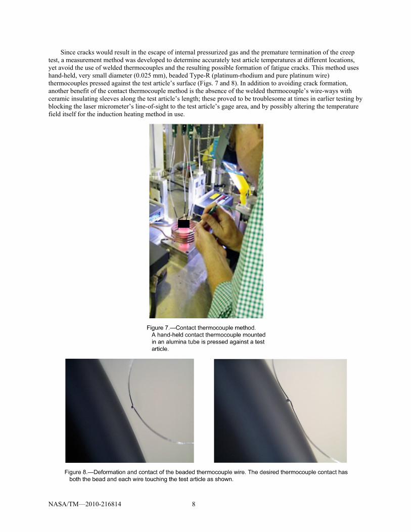
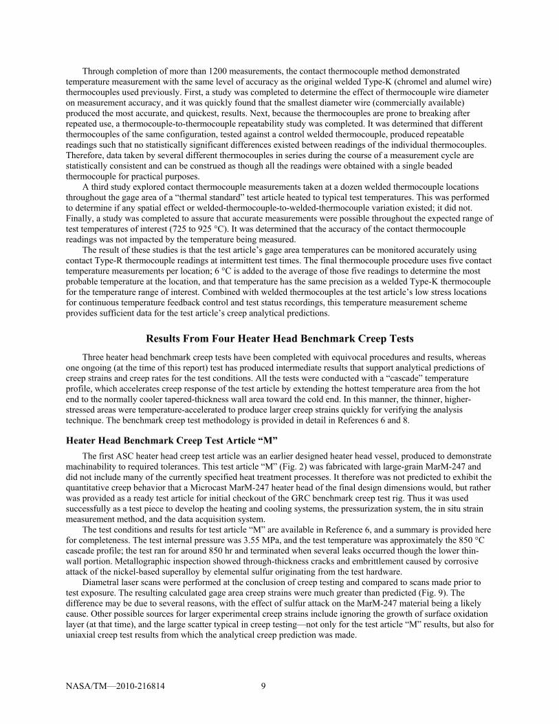
Since cracks would result in the escape of internal pressurized gas and the premature termination of the creep test, a measurement method was developed to determine accurately test article temperatures at different locations, yet avoid the use of welded thermocouples and the resulting possible formation of fatigue cracks. This method uses hand-held, very small diameter (0.025 mm), beaded Type-R (platinum-rhodium and pure platinum wire) thermocouples pressed against the test article’s surface (Figs. 7 and 8). In addition to avoiding crack formation, another benefit of the contact thermocouple method is the absence of the welded thermocouple’s wire-ways with ceramic insulating sleeves along the test article’s length; these proved to be troublesome at times in earlier testing by blocking the laser micrometer’s line-of-sight to the test article’s gage area, and by possibly altering the temperature field itself for the induction heating method in use.
NASA/TM—2010-216814 9
Through completion of more than 1200 measurements, the contact thermocouple method demonstrated temperature measurement with the same level of accuracy as the original welded Type-K (chromel and alumel wire) thermocouples used previously. First, a study was completed to determine the effect of thermocouple wire diameter on measurement accuracy, and it was quickly found that the smallest diameter wire (commercially available) produced the most accurate, and quickest, results. Next, because the thermocouples are prone to breaking after repeated use, a thermocouple-to-thermocouple repeatability study was completed. It was determined that different thermocouples of the same configuration, tested against a control welded thermocouple, produced repeatable readings such that no statistically significant differences existed between readings of the individual thermocouples. Therefore, data taken by several different thermocouples in series during the course of a measurement cycle are statistically consistent and can be construed as though all the readings were obtained with a single beaded thermocouple for practical purposes.
A third study explored contact thermocouple measurements taken at a dozen welded thermocouple locations throughout the gage area of a “thermal standard” test article heated to typical test temperatures. This was performed to determine if any spatial effect or welded-thermocouple-to-welded-thermocouple variation existed; it did not. Finally, a study was completed to assure that accurate measurements were possible throughout the expected range of test temperatures of interest (725 to 925 °C). It was determined that the accuracy of the contact thermocouple readings was not impacted by the temperature being measured.
The result of these studies is that the test article’s gage area temperatures can be monitored accurately using contact Type-R thermocouple readings at intermittent test times. The final thermocouple procedure uses five contact temperature measurements per location; 6 °C is added to the average of those five readings to determine the most probable temperature at the location, and that temperature has the same precision as a welded Type-K thermocouple for the temperature range of interest. Combined with welded thermocouples at the test article’s low stress locations for continuous temperature feedback control and test status recordings, this temperature measurement scheme provides sufficient data for the test article’s creep analytical predictions.
Results From Four Heater Head Benchmark Creep Tests
Three heater head benchmark creep tests have been completed with equivocal procedures and results, whereas one ongoing (at the time of this report) test has produced intermediate results that support analytical predictions of creep strains and creep rates for the test conditions. All the tests were conducted with a “cascade” temperature profile, which accelerates creep response of the test article by extending the hottest temperature area from the hot end to the normally cooler tapered-thickness wall area toward the cold end. In this manner, the thinner, higher-stressed areas were temperature-accelerated to produce larger creep strains quickly for verifying the analysis technique. The benchmark creep test methodology is provided in detail in References 6 and 8.
Heater Head Benchmark Creep Test Article “M”
The first ASC heater head creep test article was an earlier designed heater head vessel, produced to demonstrate machinability to required tolerances. This test article “M” (Fig. 2) was fabricated with large-grain MarM-247 and did not include many of the currently specified heat treatment processes. It therefore was not predicted to exhibit the quantitative creep behavior that a Microcast MarM-247 heater head of the final design dimensions would, but rather was provided as a ready test article for initial checkout of the GRC benchmark creep test rig. Thus it was used successfully as a test piece to develop the heating and cooling systems, the pressurization system, the in situ strain measurement method, and the data acquisition system.
The test conditions and results for test article “M” are available in Reference 6, and a summary is provided here for completeness. The test internal pressure was 3.55 MPa, and the test temperature was approximately the 850 °C cascade profile; the test ran for around 850 hr and terminated when several leaks occurred though the lower thin-wall portion. Metallographic inspection showed through-thickness cracks and embrittlement caused by corrosive attack of the nickel-based superalloy by elemental sulfur originating from the test hardware.
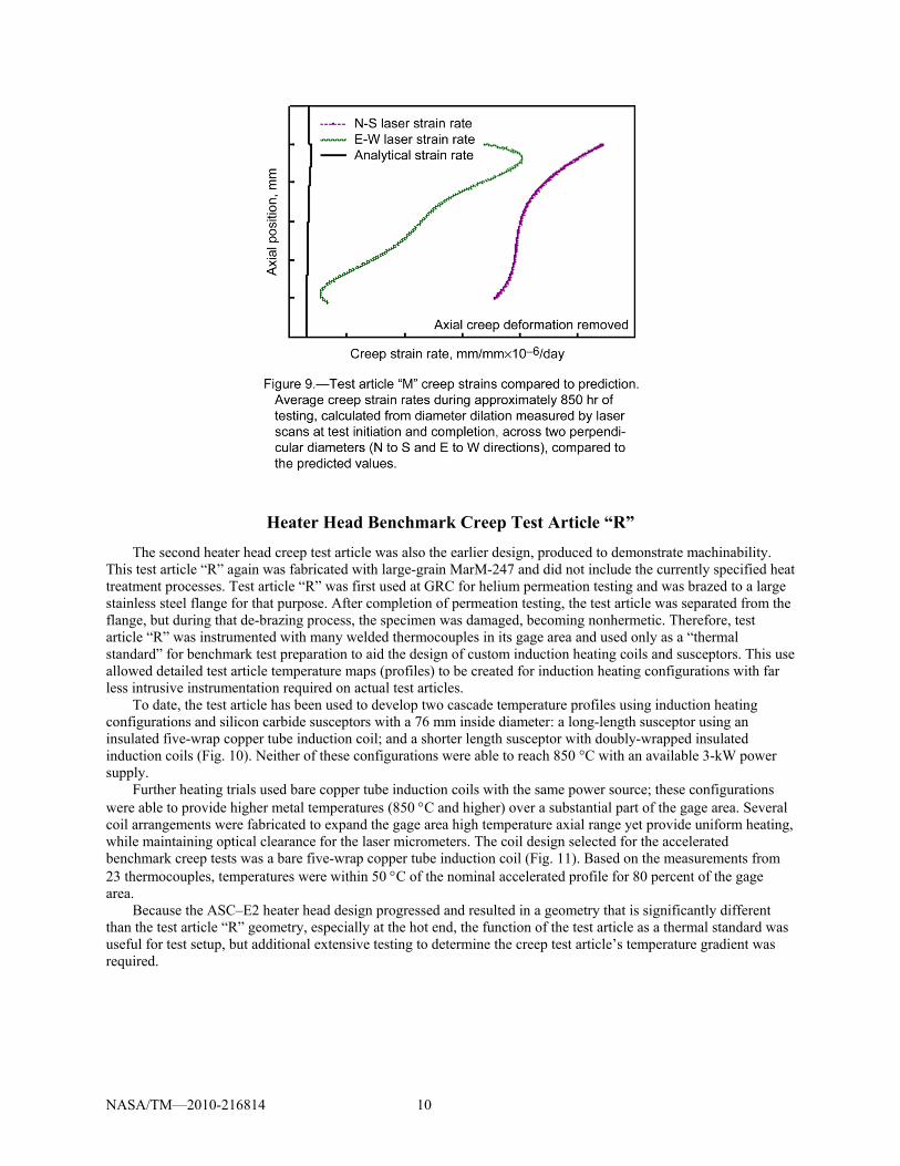
Diametral laser scans were performed at the conclusion of creep testing and compared to scans made prior to test exposure. The resulting calculated gage area creep strains were much greater than predicted (Fig. 9). The difference may be due to several reasons, with the effect of sulfur attack on the MarM-247 material being a likely cause. Other possible sources for larger experimental creep strains include ignoring the growth of surface oxidation layer (at that time), and the large scatter typical in creep testing—not only for the test article “M” results, but also for uniaxial creep test results from which the analytical creep prediction was made.
NASA/TM—2010-216814 10
Heater Head Benchmark Creep Test Article “R”
The second heater head creep test article was also the earlier design, produced to demonstrate machinability. This test article “R” again was fabricated with large-grain MarM-247 and did not include the currently specified heat treatment processes. Test article “R” was first used at GRC for helium permeation testing and was brazed to a large stainless steel flange for that purpose. After completion of permeation testing, the test article was separated from the flange, but during that de-brazing process, the specimen was damaged, becoming nonhermetic. Therefore, test article “R” was instrumented with many welded thermocouples in its gage area and used only as a “thermal standard” for benchmark test preparation to aid the design of custom induction heating coils and susceptors. This use allowed detailed test article temperature maps (profiles) to be created for induction heating configurations with far less intrusive instrumentation required on actual test articles.
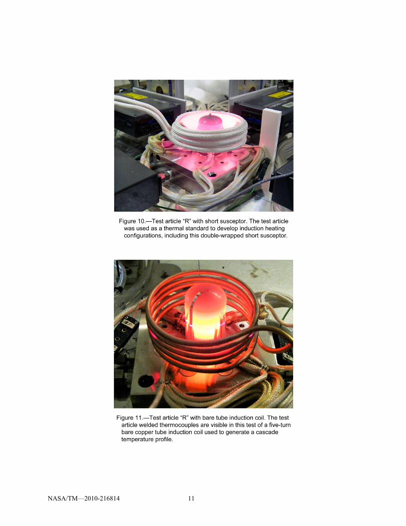
To date, the test article has been used to develop two cascade temperature profiles using induction heating configurations and silicon carbide susceptors with a 76 mm inside diameter: a long-length susceptor using an insulated five-wrap copper tube induction coil; and a shorter length susceptor with doubly-wrapped insulated induction coils (Fig. 10). Neither of these configurations were able to reach 850 °C with an available 3-kW power supply.
Further heating trials used bare copper tube induction coils with the same power source; these configurations were able to provide higher metal temperatures (850 C and higher) over a substantial part of the gage area. Several coil arrangements were fabricated to expand the gage area high temperature axial range yet provide uniform heating, while maintaining optical clearance for the laser micrometers. The coil design selected for the accelerated benchmark creep tests was a bare five-wrap copper tube induction coil (Fig. 11). Based on the measurements from 23 thermocouples, temperatures were within 50 C of the nominal accelerated profile for 80 percent of the gage area.
Because the ASC–E2 heater head design progressed and resulted in a geometry that is significantly different than the test article “R” geometry, especially at the hot end, the function of the test article as a thermal standard was useful for test setup, but additional extensive testing to determine the creep test article’s temperature gradient was required.
NASA/TM—2010-216814 11
NASA/TM—2010-216814 12
Heater Head Benchmark Creep Test Article “SN18”
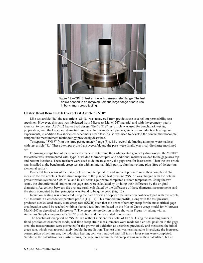
Like test article “R,” the test article “SN18” was recovered from previous use as a helium permeability test specimen. However, this part was fabricated from Microcast MarM-247 material and with the geometry nearly identical to the latest ASC–E2 heater head design. The “SN18” test article was used for benchmark test rig preparation, wall thickness and diametral laser scan hardware developments, and custom induction heating coil experiments, in addition to a shortened benchmark creep test. It also was used to develop the contact thermocouple temperature measurement methodology previously described.
To separate “SN18” from the large permeometer flange (Fig. 12), several de-brazing attempts were made as with test article “R.” These attempts proved unsuccessful, and the parts were finally electrical-discharge-machined apart.
Following completion of measurements made to determine the as-fabricated geometry dimensions, the “SN18” test article was instrumented with Type-K welded thermocouples and additional markers welded to the gage area top and bottom locations. These markers were used to delineate clearly the gage area for laser scans. Then the test article was installed at the benchmark creep test rig with an internal, high-purity, alumina volume plug (free of deleterious elemental sulfur).
Diametral laser scans of the test article at room temperature and ambient pressure were then completed. To measure the test article’s elastic strain response to the planned test pressure, “SN18” was charged with the helium pressurization system to 5.85 MPa, and in situ scans again were completed at room temperature. Using the two scans, the circumferential strains in the gage area were calculated by dividing their difference by the original diameters. Agreement between the average strain calculated by the difference of these diametral measurements and the strain computed by first principles was found to be quite good (Fig. 13).
Induction heating was completed using the bare five-wrap copper tube induction coil developed with test article “R” to result in a cascade temperature profile (Fig. 14). This temperature profile, along with the test pressure, produced a calculated steady-state creep rate (SSCR) such that the onset of tertiary creep for the most critical gage area location would be reached within a planned test duration based on the Master Curve creep model for Microcast MarM-247 as described in Reference 7. The creep rate prediction is also shown in Figure 14, along with an Arrhenius Simple creep model’s SSCR prediction and the calculated hoop stress.
The benchmark creep test of “SN18” ran without incident for a total of 187 hr. Using the scanning lasers in fixed-position extensometer mode, real-time creep strain measurements were made for a critical position in the gage area; the measurements were corrected for the growth of oxidation as described previously and measured the initial creep rate, which was approximately double the prediction. The test then was terminated to investigate the increased consumption of helium gas; the induction heating coil was removed and full in situ laser scans were completed. Similar to the calculation for elastic strains, the gage area accumulated creep strains were then calculated, but an
NASA/TM—2010-216814 13
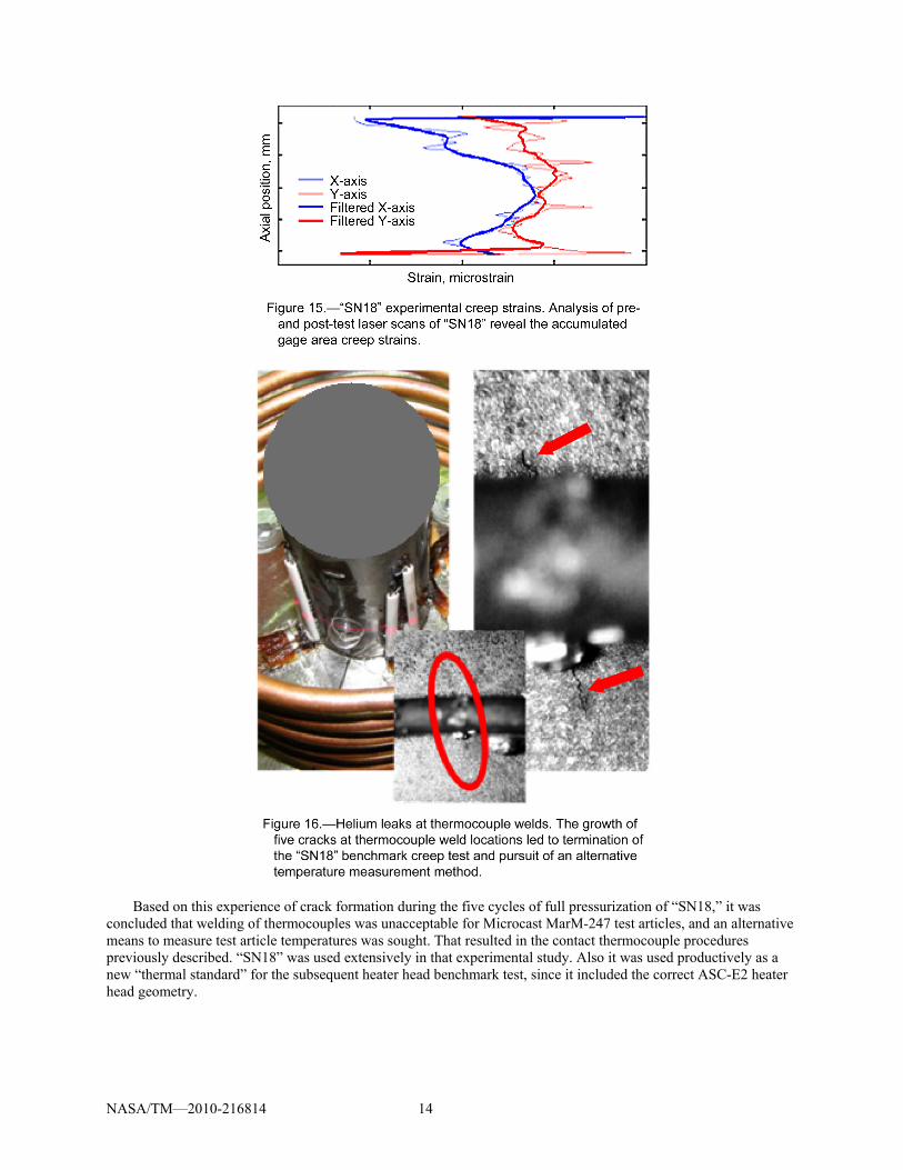
allowance for oxidation layer growth based on the test exposure was subtracted from the post-test diameter data (Fig. 15). The analysis was performed using a Matlab script that permits varied levels of smoothing but preserves the raw data for potential future use. Like the real-time measurements, results indicated that the maximum creep strains developed in the gage area were approximately two to three times the Master Curve prediction, quite a reasonably accurate prediction of the measured creep response, considering both the historically large scatter in experimental creep rates, and the fact that this measured creep rate includes primary creep if that existed. (The Master Curve prediction is for the secondary, typically lower, SSCR.) Unfortunately, the test did not run long enough to distinguish a transition to the secondary, SSCR.
The increased consumption of helium gas in the test was investigated and found to be leaks through the test article’s thin walls at thermocouple locations. Optical microscopy was used to detect five through-thickness cracks in the test article (Fig. 16). All cracks initiated at thermocouple or gage-area-marker weld locations on a plane just below the gage area; the cracks had propagated up to 1 mm in length. At this location, the temperature was approximately 600 C, and the tapered wall thickness was small, resulting in a high stress level. It was concluded that crack formation and propagation at the thermocouple welds in the Microcast MarM-247 material was likely due to high local tensile thermal stresses generated upon cooling of the molten thermocouple weld puddle and to the test conditions. Because of their location and spacing, it is believed that the presence of these defects did not affect the test article’s creep strain measurements at the critical position in the gage area.
NASA/TM—2010-216814 14
Based on this experience of crack formation during the five cycles of full pressurization of “SN18,” it was concluded that welding of thermocouples was unacceptable for Microcast MarM-247 test articles, and an alternative means to measure test article temperatures was sought. That resulted in the contact thermocouple procedures previously described. “SN18” was used extensively in that experimental study. Also it was used productively as a new “thermal standard” for the subsequent heater head benchmark test, since it included the correct ASC-E2 heater head geometry.
NASA/TM—2010-216814 15
Heater Head Benchmark Creep Test Article “C08”
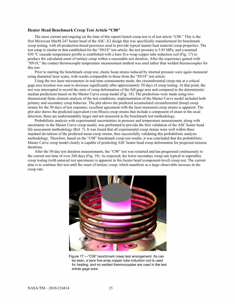
The most current and ongoing (at the time of this report) bench creep test is of test article “C08.” This is the first Microcast MarM-247 heater head of the ASC–E2 design that was specifically manufactured for benchmark creep testing, with all production-based processes used to provide typical master-heat material creep properties. The test setup is similar to that established for the “SN18” test article: the test pressure is 5.85 MPa, and a nominal 850 °C cascade temperature profile is established with a bare five-wrap copper tube induction coil (Fig. 17) to produce the calculated onset of tertiary creep within a reasonable test duration. After the experience gained with “SN18,” the contact thermocouple temperature measurement method was used rather than welded thermocouples for this test.
Prior to starting the benchmark creep test, elastic hoop strains induced by internal pressure were again measured using diametral laser scans, with results comparable to those from the “SN18” test article.
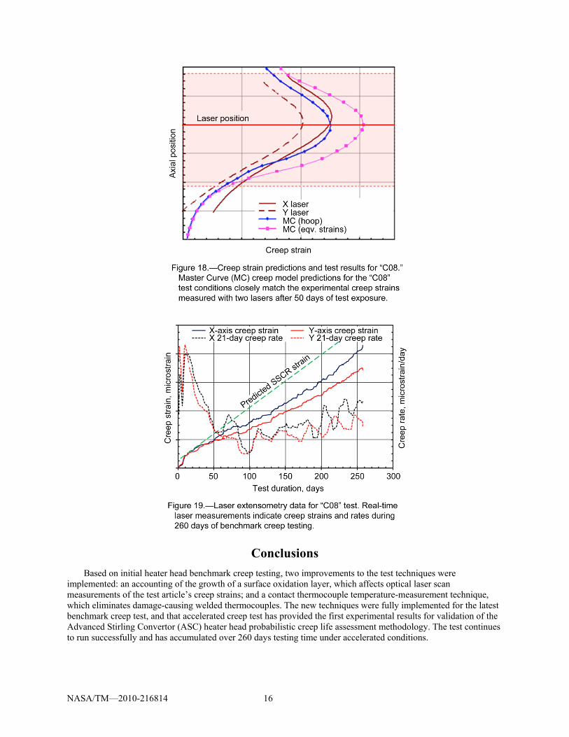
Using the two laser micrometers in real-time extensometer mode, the circumferential creep rate at a critical gage area location was seen to decrease significantly after approximately 50 days of creep testing. At that point, the test was interrupted to record the state of creep deformation of the full gage area and compared to the deterministic median predictions based on the Master Curve creep model (Fig. 18). The predictions were made using two-dimensional finite element analysis of the test conditions; implementation of the Master Curve model included both primary and secondary creep behavior. The plot shows the predicted accumulated circumferential (hoop) creep strains for the 50 days of test exposure; excellent agreement with the laser-measured creep strains is apparent. The plot also shows the predicted equivalent (von Mises) creep strains that include a component of strain in the axial direction; these are understandably larger and not measured in the benchmark test methodology.
Probabilistic analysis with experimental uncertainties in pressure and temperature measurement, along with uncertainty in the Master Curve creep model, was performed to provide the first validation of the ASC heater head life assessment methodology (Ref. 7). It was found that all experimental creep strains were well within three standard deviations of the predicted mean creep strains, thus successfully validating this probabilistic analysis methodology. Therefore, based on the “C08” benchmark creep test results, it was concluded that the probabilistic Master Curve creep model clearly is capable of predicting ASC heater head creep deformation for projected mission durations.
After the 50-day test duration measurements, the “C08” test was restarted and has progressed continuously to the current test time of over 260 days (Fig. 19). As expected, the lower secondary creep rate typical in superalloy creep testing (with uniaxial test specimens) is apparent in this heater head (component-level) creep test. The current plan is to continue this test until the onset of tertiary creep, which manifests as a large observable increase in the creep rate.
NASA/TM—2010-216814 16
Conclusions
Based on initial heater head benchmark creep testing, two improvements to the test techniques were implemented: an accounting of the growth of a surface oxidation layer, which affects optical laser scan measurements of the test article’s creep strains; and a contact thermocouple temperature-measurement technique, which eliminates damage-causing welded thermocouples. The new techniques were fully implemented for the latest benchmark creep test, and that accelerated creep test has provided the first experimental results for validation of the Advanced Stirling Convertor (ASC) heater head probabilistic creep life assessment methodology. The test continues to run successfully and has accumulated over 260 days testing time under accelerated conditions.
NASA/TM—2010-216814 17
Two additional ASC benchmark creep tests are planned that are unlike all prior creep tests; both will impose nonaccelerated, prototypical stress and temperature conditions on heater head assemblies. These tests will be used to further validate the probabilistic methodology for heater head conditions that are much closer to flight conditions.
References
1. Chan, J., Wood, J.G., and Schreiber, J.G., “Development of Advanced Stirling Radioisotope Generator for Space Exploration,” NASA/TM—2007-214806, 2007.
2. Wong, W.A., Wood, J.G., and Wilson, K., “Advanced Stirling Convertor (ASC)—From Technology Development to Future Flight Product,” NASA/TM—2008-215282, 2008.
3. Shaltens, R.K., and Wong, W.A., “Advanced Stirling Technology Development at NASA Glenn Research Center,” NASA/TM—2007-214930, 2007.
4. Schreiber, J.G., and Thieme, L.G., “GRC Supporting Technology for NASA’s Advanced Stirling Radioisotope Generator (ASRG),” Space Technology and Applications International Forum (STAIF–2008), edited by M.S. El-Genk, AIP Conference Proceedings 969, Melville, New York, 2008, pp. 582–592.
5. Bowman, R.R., “Long-Term Creep Assessment of a Thin-Walled Inconel 718 Stirling Power-Convertor Heater Head,” Proceedings of 36th Intersociety Energy Conversion Engineering Conference (IECEC), Vol. 1, AIAA Conference Proceedings 2001–CT–33, Reston, VA, 2001, pp. 435–440.
6. Krause, D.L., Kalluri, S., Bowman, R.R., and Shah, A.R., “Structural Benchmark Creep Testing for the Advanced Stirling Convertor Heater Head,” Proceedings of the 6th International Energy Conversion Engineering Conference (IECEC), AIAA Conference Proceedings 2008–5774, Reston, VA, 2008, pp. 732–741.
7. Shah, A.R., Korovaichuk, I., Krause, D.L., and Kalluri, S., “Advanced Stirling Convertor Heater Head Durability and Reliability Quantification,” Proceedings of the 6th International Energy Conversion Engineering Conference (IECEC), AIAA Conference Proceedings 2008–5772, Reston, VA, 2008, pp. 167–174.
8. Krause, D.L., Kalluri, S., and Bowman, R.R., “Structural Benchmark Testing for Stirling Convertor Heater Heads,” Space Technology and Applications International Forum (STAIF–2007), edited by M.S. El-Genk, AIP Conference Proceedings 880, Melville, NY, 2007, pp. 297–304.
9. Anonymous, “Structural Design and Test Factors of Safety for Spaceflight Hardware,” NASA Technical Standard STD–5001, Marshall Space Flight Center, Huntsville, AL, 1996.
REPORT DOCUMENTATION PAGE Form Approved
OMB No. 0704-0188 The public reporting burden for this collection of information is estimated to average 1 hour per response, including the time for reviewing instructions, searching existing data sources, gathering and maintaining the data needed, and completing and reviewing the collection of information. Send comments regarding this burden estimate or any other aspect of this collection of information, including suggestions for reducing this burden, to Department of Defense, Washington Headquarters Services, Directorate for Information Operations and Reports (0704-0188), 1215 Jefferson Davis Highway, Suite 1204, Arlington, VA 22202-4302. Respondents should be aware that notwithstanding any other provision of law, no person shall be subject to any penalty for failing to comply with a collection of information if it does not display a currently valid OMB control number. PLEASE DO NOT RETURN YOUR FORM TO THE ABOVE ADDRESS.
1. REPORT DATE (DD-MM-YYYY) 01-10-2010
2. REPORT TYPE Technical Memorandum
3. DATES COVERED (From - To)
4. TITLE AND SUBTITLE Experimental Creep Life Assessment for the Advanced Stirling Convertor Heater Head
7. PERFORMING ORGANIZATION NAME(S) AND ADDRESS(ES) National Aeronautics and Space Administration John H. Glenn Research Center at Lewis Field Cleveland, Ohio 44135-3191
8. PERFORMING ORGANIZATION REPORT NUMBER E-17382
9. SPONSORING/MONITORING AGENCY NAME(S) AND ADDRESS(ES) National Aeronautics and Space Administration Washington, DC 20546-0001
10. SPONSORING/MONITOR'S ACRONYM(S) NASA
11. SPONSORING/MONITORING REPORT NUMBER NASA/TM-2010-216814
12. DISTRIBUTION/AVAILABILITY STATEMENT Unclassified-Unlimited Subject Categories: 26 and 39 Available electronically at http://gltrs.grc.nasa.gov This publication is available from the NASA Center for AeroSpace Information, 443-757-5802
13. SUPPLEMENTARY NOTES
14. ABSTRACT The United States Department of Energy is planning to develop the Advanced Stirling Radioisotope Generator (ASRG) for the National Aeronautics and Space Administration (NASA) for potential use on future space missions. The ASRG provides substantial efficiency and specific power improvements over radioisotope power systems of heritage designs. The ASRG would use General Purpose Heat Source modules as energy sources and the free-piston Advanced Stirling Convertor (ASC) to convert heat into electrical energy. Lockheed Martin Corporation of Valley Forge, Pennsylvania, is integrating the ASRG systems, and Sunpower, Inc., of Athens, Ohio, is designing and building the ASC. NASA Glenn Research Center of Cleveland, Ohio, manages the Sunpower contract and provides technology development in several areas for the ASC. One area is reliability assessment for the ASC heater head, a critical pressure vessel within which heat is converted into mechanical oscillation of a displacer piston. For high system efficiency, the ASC heater head operates at very high temperature (850 °C) and therefore is fabricated from an advanced heat-resistant nickel-based superalloy Microcast MarM-247. Since use of MarM-247 in a thin-walled pressure vessel is atypical, much effort is required to assure that the system will operate reliably for its design life of 17 years. One life-limiting structural response for this application is creep; creep deformation is the accumulation of time-dependent inelastic strain under sustained loading over time. If allowed to progress, the deformation eventually results in creep rupture. Since creep material properties are not available in the open literature, a detailed creep life assessment of the ASC heater head effort is underway. This paper presents an overview of that creep life assessment approach, including the reliability-based creep criteria developed from coupon testing, and the associated heater head deterministic and probabilistic analyses. The approach also includes direct “benchmark” experimental creep assessment. This element provides high-fidelity creep testing of prototypical heater head test articles to investigate the relevant material issues and multiaxial stress state. Benchmark testing provides required data to evaluate the complex life assessment methodology and to validate that analysis. Results from current benchmark heater head tests and newly developed experimental methods are presented. In the concluding remarks, the test results are shown to compare favorably with the creep strain predictions and are the first experimental evidence for a robust ASC heater head creep life.15. SUBJECT TERMS Stirling cycle; Mechanical properties; Creep rupture strength; Steady state creep; Strain rate; Deformation; Life (durability); Pressure vessels; Nickel alloys; Heat treatment
16. SECURITY CLASSIFICATION OF: 17. LIMITATION OF ABSTRACT UU
18. NUMBER OF PAGES
23
19a. NAME OF RESPONSIBLE PERSON STI Help Desk (email:[email protected])
a. REPORT U
b. ABSTRACT U
c. THIS PAGE U
19b. TELEPHONE NUMBER (include area code) 443-757-5802
Standard Form 298 (Rev. 8-98)Prescribed by ANSI Std. Z39-18


![HIGH-TEMPERATURE EXPERIMENTAL ......hardening [4] and power law (Norton) creep is used to model the creep deformation during the dwell period of each forming cycle. Cyclic plasticity](https://static.documents.pub/doc/80x56/5fc43384d5073f285b2220ba/high-temperature-experimental-hardening-4-and-power-law-norton-creep.jpg)


