Research Paper Advances in River Engineering, JSCE, Vol.17, 2011, EXPERIMENTAL INVESTIGATION OF CHANNEL RESPONSES AGAINST DIFFERENT CONFIGURATIONS OF GROYNES Mohammed ALAUDDIN 1 , Takashi TASHIRO 2 and Tetsuro TSUJIMOTO 3 1 Student Member of JSCE, PhD Student, Graduate School of Engineering, Nagoya University 2 Member of JSCE, Assoc. Prof., Graduate School of Environmental Studies, Nagoya University 3 Fellow of JSCE, Prof., Graduate School of Engineering, Nagoya University (Furo-cho, Chikusa-ku, Nagoya, 464-8603, Japan) Both massive bank erosion at monsoon and lack of navigable depth at dry season are the crucial problems in Jamuna River of Bangladesh. Groynes are commonly practiced to mitigate the problems, but the suitable designs yet to be found: completely blocked impermeable groynes suffer from structural instability, and so on; whereas, fully permeable structure can not establish thalweg for navigation. A modified combined groyne is designed optimizing both alignment and permeability to improve the groyne functions, and is tested including three other models. A groyne is evaluated through three features: scour near groynes (structure stability), deposition in the groyne field (bank stability), and erosion in the main channel (navigability). Experimental data shows that the modified combined groyne decelerates the flow gradually towards the channel wall and minimizes local scour compared with other structures. Other two features are also relatively regular in the channel, but moderate in magnitude. Key Words : Jamuna river, modified combined groyne, bank erosion, deposition, scour near groyne 1. BACKGROUND Massive bank erosion at monsoon as well as insufficient depth of flow for navigation at dry season is crucial problem in sand-bed braided river, Jamuna in Bangladesh; where the groynes, bandal-like structures etc. are applied as the control measures. In case of fully blocked impermeable groynes, there is a much chance of strong recirculation of flow downstream of the structures 1-3) , which may attack the bank back again where the structures installed depending on the groyne intervals and spoil one of the major targets. Moreover, instability of the structures due to local scour is a very common problem along with destructive consequences due to hydraulic actions after their failures at downstream region planned to be protected. Sudden and big responses from these structures, in one way, leave behind strong eddies near the groyne-tip causing scour holes responsible for this structural instability 4-7) ; furthermore, these affect other regions such as islands where numbers of people are living or other bank etc. and make them unstable. Also, there is presence of huge scour due to strong parallel flow at upstream side of the groynes as observed in the field structure, where the velocity is found even higher than the main channel 8) ; which may make the structure unstable. Whereas, the bandal-like structures, as used as a recurrent method, have some positive effects in the channels, but their large-scale use at varying flow conditions are not evident yet. The disadvantages of impermeable groynes can be minimized replacing with permeable ones, which decrease flow velocities near bank, hence rapid deposition in that area; particularly, in alluvial rivers with high sediment load. The conventional permeable groynes, however, can not diverse the flow rightly and some local scour can still be present near groyne-tip or near bank, depending on the permeability provided in the structure. Also some studies were conducted on the flow from different groyne designs with straight alignment, and providing the permeable part at top and mild slope at groyne-tip 9) . There, high velocity fluctuations were marked; however, it improved over the conventional type. To surmount the drawbacks, permeability of the structure can be July - 335 -
Transcript
Research Paper Advances in River Engineering, JSCE, Vol.17, 2011,
EXPERIMENTAL INVESTIGATION OF CHANNEL RESPONSES AGAINST DIFFERENT CONFIGURATIONS OF GROYNES
Mohammed ALAUDDIN1, Takashi TASHIRO2 and Tetsuro TSUJIMOTO3
1Student Member of JSCE, PhD Student, Graduate School of Engineering, Nagoya University 2Member of JSCE, Assoc. Prof., Graduate School of Environmental Studies, Nagoya University
3Fellow of JSCE, Prof., Graduate School of Engineering, Nagoya University (Furo-cho, Chikusa-ku, Nagoya, 464-8603, Japan)
Both massive bank erosion at monsoon and lack of navigable depth at dry season are the crucial problems in Jamuna River of Bangladesh. Groynes are commonly practiced to mitigate the problems, but the suitable designs yet to be found: completely blocked impermeable groynes suffer from structural instability, and so on; whereas, fully permeable structure can not establish thalweg for navigation. A modified combined groyne is designed optimizing both alignment and permeability to improve the groyne functions, and is tested including three other models. A groyne is evaluated through three features: scour near groynes (structure stability), deposition in the groyne field (bank stability), and erosion in the main channel (navigability). Experimental data shows that the modified combined groyne decelerates the flow gradually towards the channel wall and minimizes local scour compared with other structures. Other two features are also relatively regular in the channel, but moderate in magnitude.
Key Words : Jamuna river, modified combined groyne, bank erosion, deposition, scour near groyne
1. BACKGROUND Massive bank erosion at monsoon as well as insufficient depth of flow for navigation at dry season is crucial problem in sand-bed braided river, Jamuna in Bangladesh; where the groynes, bandal-like structures etc. are applied as the control measures. In case of fully blocked impermeable groynes, there is a much chance of strong recirculation of flow downstream of the structures1-3), which may attack the bank back again where the structures installed depending on the groyne intervals and spoil one of the major targets. Moreover, instability of the structures due to local scour is a very common problem along with destructive consequences due to hydraulic actions after their failures at downstream region planned to be protected. Sudden and big responses from these structures, in one way, leave behind strong eddies near the groyne-tip causing scour holes responsible for this structural instability4-7); furthermore, these affect other regions such as islands where numbers of people are living or other bank etc. and make them unstable. Also, there is presence of huge scour
due to strong parallel flow at upstream side of the groynes as observed in the field structure, where the velocity is found even higher than the main channel8); which may make the structure unstable. Whereas, the bandal-like structures, as used as a recurrent method, have some positive effects in the channels, but their large-scale use at varying flow conditions are not evident yet. The disadvantages of impermeable groynes can be minimized replacing with permeable ones, which decrease flow velocities near bank, hence rapid deposition in that area; particularly, in alluvial rivers with high sediment load. The conventional permeable groynes, however, can not diverse the flow rightly and some local scour can still be present near groyne-tip or near bank, depending on the permeability provided in the structure. Also some studies were conducted on the flow from different groyne designs with straight alignment, and providing the permeable part at top and mild slope at groyne-tip9). There, high velocity fluctuations were marked; however, it improved over the conventional type. To surmount the drawbacks, permeability of the structure can be
July
- 335 -
varied from higher to lower value so as to achieve a gradual deceleration of flow velocities towards the bank. Thus, after gradual reduction of flow intensity, more stagnant region of flow can be developed providing impermeable portion adjacent to the bank, without influencing strong recirculation there. Therefore, a combination of permeable and impermeable groynes, inclining far-bank permeable portion towards downstream, can be an effective alternative for significant modification of fluvial processes such as strong recirculation (bank attack) and local scour (structural instability), also to concentrate the flow in the main channel to favor navigable depth. The alignment could be the same as found as optimum configuration of a groyne from the consideration of bank protection and navigation channel both10). In addition to this modified combined groyne, three other configurations are also considered in this study for comparison of performances. Thus, the present study investigates the channel responses against a series of impermeable as well as combined groynes through laboratory experiments concentrating on some key features, such as depth of scour near groyne, deposition near bank and erosion in the main channel, all aiming at improving the quality river landscapes. 2. EXPERIMENTAL SETUP AND
PROCEDURE (1) Experimental setup a) Model channel and groyne designs The experiments are performed in a tiltable open-channel flume located in the Hydraulic Engineering Laboratory of Nagoya University. The flume is straight and of rectangular cross-section, 20.0m long, 0.5m wide, 0.3m deep and is capable of a discharge not exceeding 50.0m3/hr. The side walls of the flume are made of a transparent weather-resistant acrylic sheet, thereby allowing visualization of the flow and the scour process during an experimental run. Its bed at both upstream and downstream regions is made rigid with wooden plank and extended by 5.5m and 4.5m from the inlet tank and discharge tank, respectively. Relatively fine and uniform sands with a median size d50 = 0.13mm covered the remaining area of the channel with a thickness of around 16cm. Four different sets of groyne-models are considered in this study varying both alignment and permeability, where two of them are impermeable and other two are combined. First one, M1_imp, is straight impermeable; second one, M1_comb, is also straight, but first one-third portion is impermeable
and rest part is made permeable with round sticks. Other two models (M2_imp, M2_comb) are of same alignment, first one-third of which perpendicular to the bank and later part is aligned towards 200 downstream, i.e., 700 to the direction of flow at upstream; where M2_imp is impermeable and M2_comb is combined as in M1_comb. Permeability in combined models is varied along the length and blockage percentage is reduced from 67% near impermeable part to 50% at far-end, i.e., first-half of permeable portion is of 67% blockage and rest portion is of 50%. The projected length of all groyne models is Lg = 18.0 cm. A set of six numbers of each model-structure are placed on one side of the channel perpendicular to the side. Figs. 1(a-c) depict a schematic representation of the experiment setup including side view and top view of model channel, top view of groyne models and channel cross-section, respectively. The center of the first model is 10.0 m away from the inlet boundary, which is theoretically sufficient to achieve a fully developed turbulent flow in that region. The model structures are installed with an interval Sg = 0.55m, i.e., aspect ratio Sg/Lg ≈ 3.0 and cover the total distance 2.75m by five embayments.
Fig. 1 Experimental setup: (a) side (top) and plan view (bottom) of model channel; (b) groyne models (plan view) and (c) flume
cross-section with modified combined groyne.
- 336 -
Table 1 Experimental condition for the entire test runs.
Groyne type Parameters
Impermeable Combined Flow Q (m3/hr) 12.5 16.5
Flow depth h (cm) 5.0 5.5 Mean velocity U (cm/s) 13.9 16.7 Sediment size d50 (mm) 0.13 0.13
u*/u*c 0.88 0.92 Froude number Fr 0.20 0.23
Reynolds number Re 6944 9167
chan
nel s
ide
groyne
groyne field
groyne
flow
20cm
ch
g chgf ΔZ
ΔZ ΔZ
Y
Plan view
Cross-section
mai
n ch
anne
l
scour near groyne
Fig. 2 Definition sketch of key features to evaluate performance
of a groyne. b) Experimental conditions The flow condition is adjusted by a control valve and a tail gate in the tilting flume to obtain a uniform flow condition along the channel and a bed shear velocity (u*) less than the critical shear velocity (u*c) for the approach flow to avoid bed forms at upstream of the control reach. This has been decided after some trials such that except control sections, the channel bed be remained unchanged, i.e., the condition of clear water scour, and sediment mobility is not considered for the whole channel, for the time being. Flow uniformity is verified by comparing the free-surface slope and the flume’s bed slope. Two different flow discharges and approach depths are maintained for two types of groynes considering similar mean velocity in the control area from projected area of the sructures. In all tests, the groynes are emerged and the Froude number (Fr = U/√gh) is small enough to ensure sub-critical flow and the Reynolds number (Re = Uh/ν) is high enough to ensure fully developed turbulent flow in the control section. The details of the tests undertaken, including the hydraulic and sediment transport conditions are
presented in Table 1. (2) Procedure Before starting the flow in the flume with the groyne models in place, the sediment bed surface in the working area was leveled with a scraper wooden plate mounted on a moving carriage that could ride over the steel frames on both sides. After that, the flow is allowed to enter gently in the flume; when the bed is completely wetted and then drained, a profile of the bed surface is collected. The flume is then filled slowly with water and the specific flow is allowed to run upon adjusting the downstream tail gate to maintain uniform flow and clear-water scour condition. The change of bed topography, especially the local scour depth near the first structure is monitored to identify the equilibrium condition when the rate of change decreased significantly. Then all the measurements for velocity fields, final bed topographies etc. are taken along some selected sections. To determine the performance of groyne structures, three typical features are explored rightly: depth of scour near groyne (ΔZg), deposition of sediment in the groyne field (ΔZgf) and erosion in the main channel (ΔZch) (Fig. 2). Thus the performances of the groyne models are confirmed through these features describing stability of the structures, anti-erosion of bank and maintenance of navigation channel, respectively. 3. MEASUREMENTS Bed levels are measured in the test area before the start of each test for reference and at the end of the tests, respectively; velocity measurements were taken once in every test case at equilibrium state of flow. After continuous running the flow, when the riverbed seemed to be unchanged; then that state can be assumed to be reached equilibrium state and it is considered 9.0 hrs in the tests. One test case was, however, conducted first for 18.0 hrs to recognize this time length, after which the change in bed level was found insignificant. (1) Velocity measurements Two-dimensional velocity components are measured utilizing an electromagnetic velocimeter with I-type sensor under dynamic flow conditions, which are attached to a moveable platform. The measuring devices record a signal in x- and y-directions simultaneously, which later converted into velocities in cm/s. Three measurements are taken at each point to have average value and the first groyne area is chosen for the measurements to inspect the modification of flow patterns by the
- 337 -
individual structure after coming in the flow from uninterrupted area. To grasp the velocity fields rightly, these measurements are taken along 9 transverse, from 2.5 cm upstream of first groyne to 2.5 cm upstream of the subsequent groyne and 16 longitudinal transects with 3.0 cm intervals starting at 2.5 cm from the side. The measurements are made at approximately 60% of the water depth, measured from the water surface assuming this as the depth-averaged velocity. (2) Bed level measurements After the velocity measurements, the flow is gradually decreased in such a way as to cause minimal disturbance to the bed. The channel is drained and after the bed is dry, the elevation of the bed was measured in the control area using a computer aided laser sensor. Bed levels are measured in all the groyne area along 18 longitudinal transects with 2.5 cm intervals. Three sensors are attached to a moving carriage to cover three transects at each sweep that travels on the steel frame on both sides of the channel. The x-axis is the downstream direction with x = 0 at center of the first groyne; y-axis is pointing towards the left side in the transverse direction with y = 0 at the right-side where the groynes are placed; and z starts from the initial loose bed-level with upward positive. The velocity components u and v are corresponding to their directions x and y, respectively. 4. ANALYSIS OF DATA As the main two purposes of installing groynes are bank protection through deposition of fine sand near bank and maintaining thalweg for navigation, three typical features: scour depth near groyne, height of deposition of sediment in the groyne field and depth of erosion in the main channel, are considered to confirm the performance of groynes. Velocity distributions as well as bed topographies measured with the available setup are presented here to understand the modification of fluvial processes and to explore all the features. (1) Flow fields Fig. 3(a) depicts the depth-averaged flow fields in the first groyne area caused by the model structures. It is seen here that velocity vectors in case of combined groynes (M1_com, M2_com) are significantly reduced in the groyne field near bank and no strong recirculation of flow is observed as found for impermeable groynes (M1_imp, M2_imp). These return currents, if groynes are not closely spaced, are sometimes dangerous at high flood time to cause scour near bank and hence bank recession,
rather than developing stable riverine landscape. This modification of flow-fields can be attributed to the permeable components of the structures and gradual reduction of permeability along the length of groynes towards the side. (2) Bed levels From the bed topographies depicted in Fig. 3(b), (relatively) higher impact near the first structure causing deeper scour as well as higher erosion in the channel bed, can be marked. Dimensionless transverse distributions of erosion and deposition averaged over the area between second and fourth groynes for impermeable case and second and fifth groynes for combined case are shown in Fig. 4, to recognize the influence of different models in the main channel and groyne field, respectively. Here, the data are made dimensionless by depth of flow in impermeable case (himp). Channel ripples of various dimensions are observed in the control area with larger dimension in the main channel and smaller extent in the groyne field, not in the upstream part of the area. As local scour around the first groyne was significantly more pronounced than that in the cases of other groynes, so this can be explained from the fact that the first groyne is exposed to the strongest current, which results in an increased erosion rate. It can also be mentioned here that for impermeable cases, the flow is highly diverted, so that it is reflected from the other side of the channel and turned back to attack the downstream embayments causing much scour near groynes there. This is an important point to note here that the impact by the back flow can even be higher than that happened around the first structure; last groyne area, however, is not covered in the figure (Fig. 3(b)). 5. PERFORMANCE OF GROYNES The performance of a groyne is evaluated through three key features: scour near the groyne, deposition in the groyne field and erosion in the main channel; where the first one signifies the stability of the structure, the second one the anti-erosion of bank and the third one for maintenance of navigation depth in the main channel. The measured maximum scour depth near the first groyne, average deposition in the groyne field and average erosion in the channel bed from 25 cm to 45 cm from the groyne side, are summarized in Table 2. The data for deposition and erosion are averaged over the area between second and fourth groynes for impermeable and second and fifth groynes for permeable ones. Also these data are depicted with a figure (Fig. 5) for clear understanding
- 338 -
Velocity fields (1st groyne area) Bed topography
zb: -4 -3 -2 -1 0 1 2 3 4 M
1_im
p
M1_
com
b
M2_
imp
M2_
com
b
(a) (b) Fig. 3 (a) Velocity fields and (b) bed topographies from different model-structures. (all units are in cm, except
velocity in cm/s)
z b/h
imp
y/Lg
Fig. 4 Transverse distributions of erosion and deposition from different model-structures.
of the variation of the features among the various groynes. Here better responses in the channel can be recognized due to both alignment and permeability: local scour reduces from M1_imp to M1_comb and M2_imp to M2_comb, also from M1_imp to M2_imp
Table 2 Dimensionless features of four groyne models.
Groyne typeGroyne
model Dimensionless features Imp. Comb.
Max. scour near groyne ΔZg/himp 1.15 0.85Depos. in groyne field ΔZgf/himp 0.01 0.06M1
Erosion in main channel ΔZch/himp 0.09 0.03Max. scour near groyne ΔZg/himp 0.91 0.70Depos. in groyne field ΔZgf/himp 0.09 0.05M2
Erosion in main channel ΔZch/himp 0.09 0.08 and M1_comb to M2_comb. However, this trend can not be recognized rightly for other features: deposition is found higher for M2_imp and lower for M1_imp; again erosion in the main channel is observed higher for M1_imp, M2_imp and then M2_comb, and it was observed relatively uniform for M2_comb (Fig. 3(b)).
0 100 2000
25
50
0 50 100 150 2000
25
50
0 100 2000
25
50
0 100 2000
25
50
-0.3
0.0
0.3
0.0 0.7 1.4 2.1 2.8
M1_imp M1_combM2_imp M2_comb
initial bed
0 20 40 600
10
20
30
40
50 150 20 40 600
10
20
30
40
50 15
0 20 40 600
10
20
30
40
50 15
0 20 40 600
10
20
30
40
50 15
- 339 -
Δ
Z g/h
imp,
ΔZgf
/him
p,ΔZ
/h
0.0
0.5
1.0
1.5
M1_mp M2_imp M1_comb M2_comb
Local scourDeposition in groyne fieldErosion in main channel
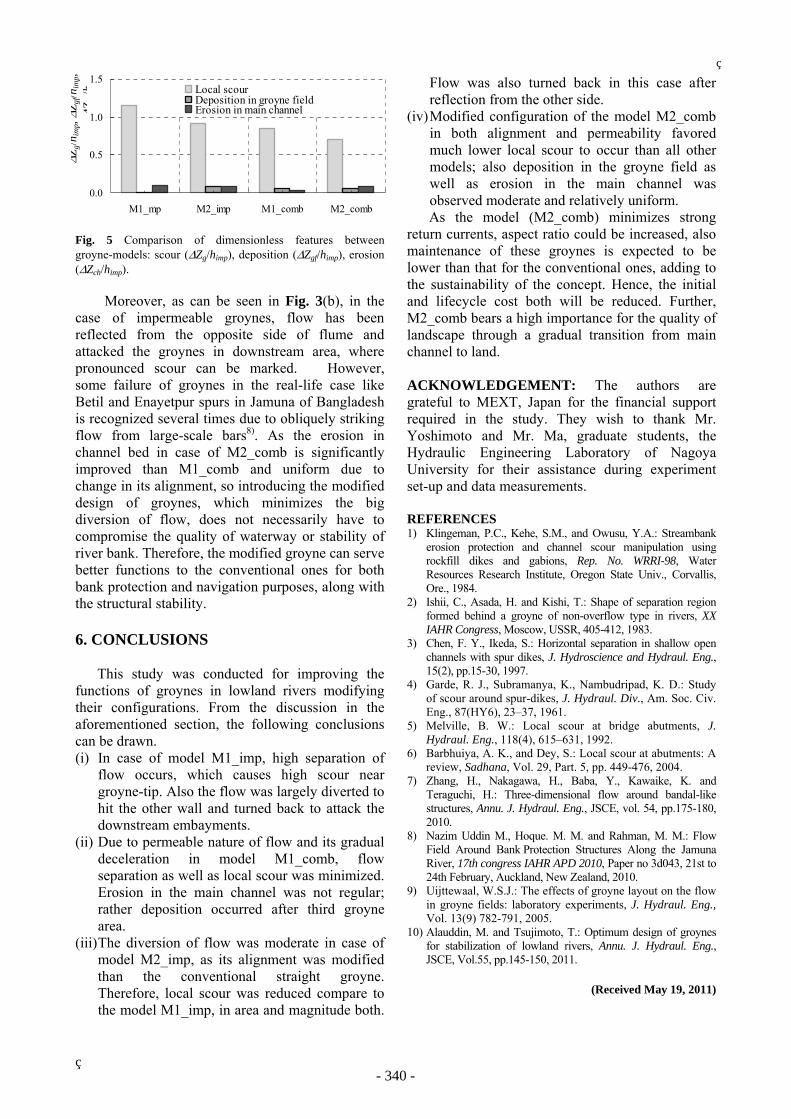
Fig. 5 Comparison of dimensionless features between groyne-models: scour (ΔZg/himp), deposition (ΔZgf/himp), erosion (ΔZch/himp).
Moreover, as can be seen in Fig. 3(b), in the case of impermeable groynes, flow has been reflected from the opposite side of flume and attacked the groynes in downstream area, where pronounced scour can be marked. However, some failure of groynes in the real-life case like Betil and Enayetpur spurs in Jamuna of Bangladesh is recognized several times due to obliquely striking flow from large-scale bars8). As the erosion in channel bed in case of M2_comb is significantly improved than M1_comb and uniform due to change in its alignment, so introducing the modified design of groynes, which minimizes the big diversion of flow, does not necessarily have to compromise the quality of waterway or stability of river bank. Therefore, the modified groyne can serve better functions to the conventional ones for both bank protection and navigation purposes, along with the structural stability. 6. CONCLUSIONS This study was conducted for improving the functions of groynes in lowland rivers modifying their configurations. From the discussion in the aforementioned section, the following conclusions can be drawn. (i) In case of model M1_imp, high separation of
flow occurs, which causes high scour near groyne-tip. Also the flow was largely diverted to hit the other wall and turned back to attack the downstream embayments.
(ii) Due to permeable nature of flow and its gradual deceleration in model M1_comb, flow separation as well as local scour was minimized. Erosion in the main channel was not regular; rather deposition occurred after third groyne area.
(iii) The diversion of flow was moderate in case of model M2_imp, as its alignment was modified than the conventional straight groyne. Therefore, local scour was reduced compare to the model M1_imp, in area and magnitude both.
Flow was also turned back in this case after reflection from the other side.
(iv) Modified configuration of the model M2_comb in both alignment and permeability favored much lower local scour to occur than all other models; also deposition in the groyne field as well as erosion in the main channel was observed moderate and relatively uniform.
As the model (M2_comb) minimizes strong return currents, aspect ratio could be increased, also maintenance of these groynes is expected to be lower than that for the conventional ones, adding to the sustainability of the concept. Hence, the initial and lifecycle cost both will be reduced. Further, M2_comb bears a high importance for the quality of landscape through a gradual transition from main channel to land. ACKNOWLEDGEMENT: The authors are grateful to MEXT, Japan for the financial support required in the study. They wish to thank Mr. Yoshimoto and Mr. Ma, graduate students, the Hydraulic Engineering Laboratory of Nagoya University for their assistance during experiment set-up and data measurements. REFERENCES 1) Klingeman, P.C., Kehe, S.M., and Owusu, Y.A.: Streambank
erosion protection and channel scour manipulation using rockfill dikes and gabions, Rep. No. WRRI-98, Water Resources Research Institute, Oregon State Univ., Corvallis, Ore., 1984.
2) Ishii, C., Asada, H. and Kishi, T.: Shape of separation region formed behind a groyne of non-overflow type in rivers, XX IAHR Congress, Moscow, USSR, 405-412, 1983.
3) Chen, F. Y., Ikeda, S.: Horizontal separation in shallow open channels with spur dikes, J. Hydroscience and Hydraul. Eng., 15(2), pp.15-30, 1997.
4) Garde, R. J., Subramanya, K., Nambudripad, K. D.: Study of scour around spur-dikes, J. Hydraul. Div., Am. Soc. Civ. Eng., 87(HY6), 23–37, 1961.
5) Melville, B. W.: Local scour at bridge abutments, J. Hydraul. Eng., 118(4), 615–631, 1992.
6) Barbhuiya, A. K., and Dey, S.: Local scour at abutments: A review, Sadhana, Vol. 29, Part. 5, pp. 449-476, 2004.
7) Zhang, H., Nakagawa, H., Baba, Y., Kawaike, K. and Teraguchi, H.: Three-dimensional flow around bandal-like structures, Annu. J. Hydraul. Eng., JSCE, vol. 54, pp.175-180, 2010.
8) Nazim Uddin M., Hoque. M. M. and Rahman, M. M.: Flow Field Around Bank Protection Structures Along the Jamuna River, 17th congress IAHR APD 2010, Paper no 3d043, 21st to 24th February, Auckland, New Zealand, 2010.
9) Uijttewaal, W.S.J.: The effects of groyne layout on the flow in groyne fields: laboratory experiments, J. Hydraul. Eng., Vol. 13(9) 782-791, 2005.
10) Alauddin, M. and Tsujimoto, T.: Optimum design of groynes for stabilization of lowland rivers, Annu. J. Hydraul. Eng., JSCE, Vol.55, pp.145-150, 2011.