40
m EXPERIMENTAL TECHNIQUES IN NUCLEAR PHYSICS by R. K. Choudhury Nuclear Physics Division 1999 J>

m
EXPERIMENTAL TECHNIQUES IN NUCLEAR PHYSICSby
R. K. ChoudhuryNuclear Physics Division
1999
J>
BARC/1999/E/022
5 GOVERNMENT OF INDIA§ ATOMIC ENERGY COMMISSION03
EXPERIMENTAL TECHNIQUES IN NUCLEAR PHYSICS
by
R.K. ChoudhuryNuclear Physics Division
BHABHA ATOMIC RESEARCH CENTREMUMBAI, INDIA
1999
BARC/1999/E/022
BIBLIOGRAPHIC DESCRIPTION SHEET FOR TECHNICAL REPORT(as per IS : 9400 - 1980)
01
02
03
04
05
06
07
08
10
11
13
20
21
22
23
24
Security classification :
Distribution :
Report status :
Series :
Report type :
Report No. :
Part No. or Volume No. :
Contract No. :
Title and subtitle :
Collation :
Project No. :
Personal author(s) :
Affiliation of author(s) :
Corporate author(s) :
Originating unit :
Sponsor(s) Name :
Type :
Unclassified
External
New
BARC External
Technical Report
BARC/1999/E/022
Experimental techniques in nuclear physics
38 p., 12 figs., 4 tabs.
R. K. Choudhury
Nuclear Physics Division, Bhabha Atomic Research Centre,Mumbai
Bhabha Atomic Research Centre, Mumbai - 400 085
Nuclear Physics Division,BARC, Mumbai
Department of Atomic Energy
Government
Contd... (ii)-i-
30 Date of submission : August 1999
31 Publication/Issue date : September 1999
40 Publisher/Distributor : Head, Library and Information Services Division,
Bhabha Atomic Research Centre, Mumbai
42 Form of distribution : Hard copy
50 Language of text : English
51 Language of summary : English
52 No. of references : 12 refs.
53 Gives data on :
Abstract : A variety of experimental techniques involving wide varieties of nuclear radiationdetection methods are required to carry out research in different areas of nuclear physics.The progress in the design and operation of nuclear radiation detectors in various applicationshas been very rapid and a periodic review in this field is always appropriate. The presentreport, while dealing with the general principles of particle and radiation detection usingconventional detectors of gas, scintillator and semiconductor types, also gives an update ofthe recent developments in sophisticated detector systems which are built to meet therequirements of present day nuclear physics experiments.
70 Keywords/Descriptors : CHERENKOV COUNTERS; SHOWER COUNTERS;ELECTROMAGNETIC RADIATION; PARTICLE INTERACTIONS; PHOTONS;NEUTRONS; STOPPING POWER; IONIZATION CHAMBERS; PROPORTIONALCOUNTERS; SCINTILLATION COUNTERS; SPECIFICATIONS; PARTICLEIDENTIFICATION; SEMICONDUCTOR DETECTORS
71 INIS Subject Category : E4130
99 Supplementary elements :
-it-
EXPERIMENTAL TECHNIQUES IN NUCLEAR PHYSICS
R.K. CHOUDHURY
ABSTRACT
A variety of experimental techniques involving wide varieties of nuclear
radiation detection methods are required to carry out research in different areas
of nuclear physics. The progress in the design and operation of nuclear radiation
detectors in various applications has been very rapid and a periodic review in
this field is always appropriate. The present report, while dealing with the
general principles of particle and radiation detection using conventional
detectors of gas, scintillator and semiconductor types, also gives an update of the
recent developments in sophisticated detector systems which are built to meet
the requirements of present day nuclear physics experiments.
CONTENTS
1. Introduction 1
2. Principles of particle detection 1
3. Particle detectors 11
4. Cherenkov radiation and Cherenkov counters 22
5. Electromagnetic calorimeters 25
6. Particle identification techniques 27
7. PHENIX detector 29
8. Summary 32

EXPERIMENTAL TECHNIQUES IN NUCLEAR PHYSICS
R. K. CHOUDHURY
1 Introduction
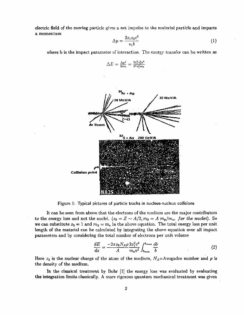
Progress in experimental nuclear and particle physics has been closely associated with thedevelopments in the accelerator and detector technologies. Presently, with the use of largeaccelerator facilities, it has been possible to achieve centre mass energies upto a few hundredGeV/nucleon either in fixed target accelerators or with collider beams, which enables one toinvestigate the unexplored regions of nuclear phenomena. Accelerator based experiments areplanned depending on the ability of the researcher to detect and characterize the particlesproduced in the collisions of the target and projectile nuclei.With increasing bombardingenergy the complexity of the heavy ion collisions increases as one can see from the pictures(shown in fig.l) of some typical collisions in the high energy heavy ion experiments . In orderto cope with the increasing demands of the experiments for higher detection capabilities interms of sensitivity and better resolution, the detection equipments have undergone majordevelopments in many different aspects.The developments have taken place in (i) the sizeand complexity of the detection system (ii) the speed of data collection, (iii) the versatilityof the detector techniques (iv) the reliability of the equipment through innovations in faston-line control and monitoring of the experimental set up. The present series of lectures isaimed at providing some' discussions on the basic concepts of the detection methods and thetechniques used in the experimental setups at intermediate and relativistic energies.
2 Principles of particle detection
Before a particle can be detected, it must first undergo some sort of interaction with thematerial of a detector. Electromagnetic interactions are the most important of all processesfor particle detection. Other type of interactions such as strong and weak nuclear interactionsare important for detection of neutral particles.
2.1 Interaction of charged particles with matter
We will begin by considering the kinetic energy loss of an incident charged particle due toits Coulomb interaction with the charged particles in matter. Let the incident particle havemass mi, charge z^e and velocity v\. We assume it to interact with a particle in the materialwith mass 7712 and charge Z^e and that the material particle is at rest. The moving chargecreates an electric and magnetic field at the location of the material particle. The magneticinteraction is not important, since the material particle is essentially at rest. The changing
electric field of the moving particle gives a net impulse to the material particle and impartsa momentum
2
where b is the impact parameter of interaction. The energy transfer can be written as
32 MeWA
Collision point
Figure 1: Typical pictures of particle tracks in nucleus-nucleus collisions
It can be seen from above that the electrons of the medium are the major contributorsto the energy loss and not the nuclei, {z-i — Z ~ A/2, ni2 = A mp/mef for the nuclei). Sowe can substitute z-i — 1 and m<i — me in the above equation. The total energy loss per unitlength of the material can be calculated by integrating the above equation over all impactparameters and by considering the total number of electrons per unit volume
dx> 2z\eA rb">°* dbmev
2 Jbmin b(2)
Here z-i is the nuclear charge of the atom of the medium, iV4=Avogadro number and p isthe density of the medium.
In the classical treatment by Bohr [1] the energy loss was evaluated by evaluatingthe integration limits classically. A more rigorous quantum mechanical treatment was given

by Bethe and Bloch [2], where the energy loss was calculated by classifying the collisions asdistant and close collisions depending on the amount of energy transfer involved. For distantcollisions, the incident particle interacts with the atom as a whole and causes excitation ofan electron to a higher energy level or ionisation. For close collisions, the interaction can beconsidered to be with free electrons and the energy loss is calculated using the appropriateinteraction crosssection. The total energy loss is the sum of the contributions from close anddistant collisions and is given by
dx tneVi
where ne =or
where2
K - 47r(-^r)2mec2 = 5.0989 x 1(T25MeVcm2 (5)
7 = (1 - /?2)-i and 0 = *•
Now let us consider the important features of the above equation. The energy lossdepends quadratically on the charge and velocity of the particle but not on its mass. Themedium dependence comes linearly through ne and logarithmically through mean ionisationpotential I. As the velocity of the particle increases from near zero, dE/dx falls as l/«2 ,goes through a minimum with dE/dx ~ 2MeV/(g/cm2) for (3y « 3 and then continuesto increase due to the In 72 factor. However, at very large values of 7, there is a densityeffect due to dielectric screening of projectiles electric field, causing the energy loss to nearlysaturate for large values of /?7(> 100). Taking the density effect into account, the energyloss formula can be written as
^ = -5.0989 x i o - > V ( ^ ) 2 [ l n ( ^ 4 ^ ! ) - /?2 - ^ ] MeV/an (6)
It may also be noted that at low energies (^ < 1 — 2MeV/n), the charge of the particlecannot be considered as bare nuclear charge due to the recombination of electrons and theionic charge (ze//) comes into play for calculating the energy loss. A simple relationship forthe effective charge is given by
Ze/f = £i(l - Aexp(-BvR))
where VR is defined as the ratio of the ion velocity to the Thomas-Fermi electron velocity(VR = v/vozs), VQ being the orbital velocity of the electron in the first Bohr orbit. Due tothe effective charge, the energy loss decreases again at low particle energies.
The essential features of the energy loss of charged particles in a medium can beseen from fig.2, where we have shown the normalised energy loss -\(dE/dx) as a function

.001id5 id4 id3 id2 id1 1 10 io 2 io3 id4 io 5 io6
E/m ( McV/amu )
Figure 2: Stopping power curves for various heavy ions
of E/m for a number of heavy ions in aluminium over a wide energy region. At very lowenergies, there is an additional "nuclear" contribution to the energy loss due to energytransfer to screened nuclei of the medium as shown by the deviation of the total stoppingpower (continuous line) from the electronic part (dashed line). At very high velocities, thereis a universal behaviour of the energy loss for all the ions as expected from eq.(6) above.
2.1.1 Range of a particle
The range represents the distance transversed by a particle along its trajectory.
(7)dx
let us write f = z\f{v) = *fhence
( -
m m(8)
where g is a universal function of E/m. From above one can write the scaling law for rangeas
(E2 m2z\ E2
Hence if the range of some particle (say proton) is known as a function of v or E/m,one can obtain the range of another particle of any given energy using the above relationship.A simple empirical expression for the range energy relationship of proton is
= (§-r (10)

where range is measured in meters, and Eo = 9.3 MeV, n = 1.8 for protons in air,which can be used handily to evaluate the range of other particles in air.
2.1.2 Energy loss in mixtures and compounds
For mixtures and compounds, one can write
l.dE. ..dE.- ( - ) m = EM,(^)< (11)
where, ai= Number of atoms of ith element,Ai = Atomic weight of ith element,Am= J2i ai-Ai, is the total atomic weight , andp— density of mixture or compound
One can also define effective values of different quantities and use them in the originalformula (6) as :
Zeff = £ i OiZi Aeff = J
2.2 Interaction of electrons and positrons with matter
Electrons and positrons lose energy by ionization and excitation during the collision withelectrons in the medium-just as other heavier charged particles. However, because of theirsmall mass, they also lose energy due to production of bremsstrahlung radiation duringacceleration or deceleration process in the vicinity of the atoms of the medium. The totalenergy loss for electrons and positrons, therefore, is composed of two parts
,dE. .dE. ,dE.
2.2.1 Collisional loss
The total energy loss for electrons and positrons, due to collisions with electrons of themedium, is given by the following expressions :
" Vm tc2 '
where
T = j^g, T=kinetic energy of e or e+
and
The difference between e and e+ arises due to use of Moller and Bhabha scatteringcrosssection for the collisions for the two cases.
2.2.2 Bremsstrahlung loss
The radiation loss depends on the bremsstrahlung emission probability which varies as inversesquare of particle mass
_ _. Jl _ / e 12
The radiation loss by heavy particles such as muons (m~106 MeV) is 40000 times lower thanthat for electrons.
Since bremsstrahlung emission depends on the strength of the electric field felt by theelectron, the amount of screening of the nuclear charge by the atomic electrons plays animportant role. The effect of screening can be parametrized by the quantity as
r _ 100mec2(E0-E)
* " EoEZl { }
where (EQ — E) = hv — energy of photon, Eo= initial energy, E = final energy ofelectron.
When £ —> 0, hv —> 0: complete screening
£ —• oo, hv —> EQ : No screening
For relativistic energies, Eo > a few MeV, the bremsstrahlung crosssection due tonuclear charge, Z is given by
* ^ " 1 + ^ * F ¥where e = E/Eo, f(Z) = Coulomb correction and <£i,<̂ 2 are the screening functions.
In the limiting cases of no screening and complete screening, one can write simpleranalytic forms for the bremstrahlung crosssection as
i) No screening (f >> 1)
ii) Complete screening (£ = 0)
da = 4 Z \ a | ^ [ ( l + , 2 - |)(In(183Z-*) - f(Z)) + | ] (17)
The energy loss due to radiation can be written as
-(-r-)rad = ^ / . ^ , du = NE0(j>ra(l; <f>rad = — / to/—^ Ldv (18)
Since % oc ^ , on"e can see that (f>rad is practically independent of v and is a functionof material only.
Again, one can write
for i » 1 , 4>rad = 4ZV^[ln(Sr) - | - f(Z)} and
for £ = 0 , <j>rad = 4Zr e g[ ln(183Z^) - i
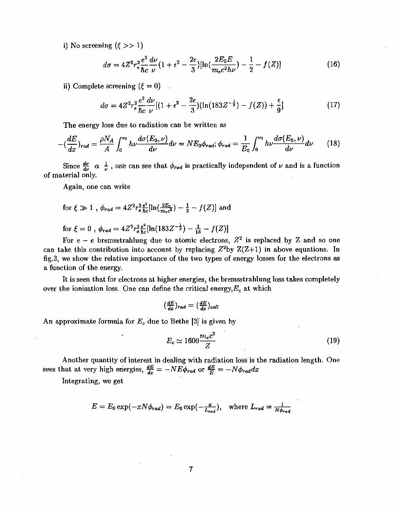
For e — e bremsstrahlung due to atomic electrons, Z2 is replaced by Z and so onecan take this contribution into account by replacing Z2by Z(Z+1) in above equations. Infig. 3, we show the relative importance of the two types of energy losses for the electrons asa function of the energy.
It is seen that for electrons at higher energies, the bremsstrahlung loss takes completelyover the ionisation loss. One can define the critical energy,!^ at which
(dE\ _ (dE_\
An approximate formula for Ec due to Bethe [3] is given by
^ (19)
ZAnother quantity of interest in dealing with radiation loss is the radiation length. One
sees that at very high energies, ^f = -NE(j>Tad or ^ = -N<j>raddx
Integrating, we get
= E0 exp(-xN(j>rad) = Eo exp(-jf-), where Lrad = j ^

10
10-1
Copper
Br ems str ahlungloss
collision loss,/
10 1 10 10Energy (JVIeV )
Figure 3: Radiation loss Vs Collision loss for electrons in Copper
Hence, the radiation length Lrad can be defined as the length of material required toreduce the energy of electron by 1/e of the original value. Material thickness is usuallymeasured in unit of radiation length so that radiation energy loss per unit thickness (t =x/Lrad) is roughly independent of material type. In table 1, we give the values of Ec andLrad f°r some of the commonly used materials in detector fabrication.
Material
AirH2OOrganic Scint.PolyestereneAlCuPbFeBGO(BiGe3O12)BaF2
Nal
Ec(MeV)
102921051095124.89.5127.413.117.817.4
Lradcm3005036.142.442.98.91.430.561.761.122.052.59
fimcm?36.236.0843.843.824.0112.866.3713.847.989.919.49
Table 1.
From this table one can determine the effectiveness of different materials in stoppingthe high energy electrons.
8

2.3 Interaction of photons with matter
Photon interactions are different from that of charged particles in the sense that there isa large probability that an interacting photon can be removed from the beam. There arethree major processes by which photons interact with matter : i) Photo-electric ii) Comptonscattering and iii) Pair production.
The Photo-electric crosssection is given by
hcr>'p e r atcm " wAt very low energy, the photo-electron is emitted at 90° to photon direction, but as
the photon energy increases, the emission becomes more and more forward peaked.
In Compton scattering, the incident photon gets scattered by a free electron of theatom imparting it certain energy and coming out with a reduced energy. The differentialcrosssection for scattering is given by the Klein-Nishina formula as [3] :
^fj — ~2"fT~' hi/ /. T ^ r l l 4" COS
The total crosssection is given by
The maximum energy of electron allowed by kinematics is when the photon is scatteredby 180° and is given by
2 hu
max = nV ITT— \£&)
The Compton scattering gives a continuous distribution of electron energy with theabove maximum called the Compton edge. For photon energies much greater than mec
2, theCompton edge comes about mec
2/2 less than the photopeak energy.
In pair production, the photon energy is converted to the toal energy of an electron-positron pair. Pair production is similar to the bremsstrahlung emission and involves similarscreening parameter. The total pair production crosssection for the two extreme cases ofscreening is given by
i) No screening (£ >> 1) (low energy)
ii) Complete screening (£ —> 0) (high energy)
apair = AZ^rlf-MlSZZ-l) - f(Z)] - JL] (24)
Pair production in the field of electrons goes as Z instead of £T2 and hence the totalcrosssection can be obtained by replacing Z2 by Z(Z-f 1) in the above equations.
The mean free path for pair production can be obtained as
NcTpa.r
which is close to the radiation length discussed above.
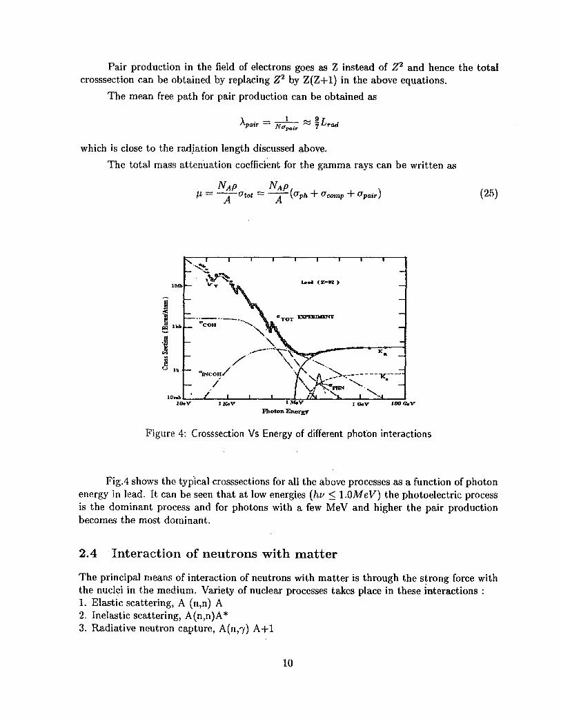
The total mass attenuation coefficient for the gamma rays can be written as
~Ot0t ~apair) (25)
1M.VPhoton Energy
I GeV I0O C V
Figure 4: Crosssection Vs Energy of different photon interactions
Fig.4 shows the typical crosssections for all the above processes as a function of photonenergy in lead. It can be seen that at low energies (hv < l.OMeV) the photoelectric processis the dominant process and for photons with a few MeV and higher the pair productionbecomes the most dominant.
2.4 Interaction of neutrons with matter
The principal means of interaction of neutrons with matter is through the strong force withthe nuclei in the medium. Variety of nuclear processes takes place in these interactions :1. Elastic scattering, A (n,n) A2. Inelastic scattering, A(n,n)A*3. Radiative neutron capture, A(n,7) A+l
10

4. Nuclear reactions, (n,p), (n,d), (n,oi) (n, fission)
The total crosssection is given by sum of all these crosssections:
Gtot = &el + &inel + Ocap + (^reaction
There are strong variations of otot with energy of neutron, A and Z of the nucleus ofthe medium. At low energies, the capture crosssection goes as 1/v, but at somewhat higherenergies, there can be strong resonances corresponding to the nuclear levels in the compoundnucleus. For low A nuclei, the scattering is the dominant mode for stopping the neutronsthrough moderation. Both the processes of scattering and reactions are used in the detectormedia to detect the neutrons.
3 Particle detectors
All particle detectors are based on the fundamental principle that the transfer of part orall of the radiation energy in the detector material is converted into some other form moreaccessible to human perception. The form in which the converted energy appears depends onthe detector and its design. In gaseous and semiconductor detectors the ionisation processleads to some sort of current signal, while in scintillation detectors the interactions leadto emission of light. Similarly in photographic emulsions and nuclear track detectors, theionisation induced effects lead to formation of an image of the track. The first considerationof a detector is its sensitivity, i.e. its capability to produce a usable signal for a given type ofradiation and energy. The second consideration is its resolution in determination of particletype and energy. We shall briefly describe in this section the principles behind differenttypes of detectors used in the nuclear and particle physics experiments.
3.1 Gas detectors
Gas ionisation detectors were the first electrical devices developed for radiation detectionduring the 1940's. With the development of scintillation and semiconductor detectors inthe 1950's and 1960's, the use of gas detectors were on the wane. However, during latesixties, the development of multiwire chambers and also the advent of heavy ion acceleratorsfor the study of heavy ion reactions saw a renewed interest in the use of gas detectors inthe nuclear physics experiments. Gas detectors offer several advantages over other types ofdetectors. These are (i) Versatility in the size, shape of the detector (ii) no radiation damage(iii) Control on effective detector thickness by varying the gas pressure (iv) multiple modeof operation and pulse readout procedure, and (v) fairly good resolution and linearity inenergy and position determination of the interacting particle etc. We shall briefly discussthe different types of gas detectors that are used in the experimental set ups in nuclearphysics experiments.
11

3.1.1 Parallel plate ionisation chamber
Simplest among the gas detectors is the parallel plate gas ionisation chamber, in which auniform electric field is applied across the sensitive gas volume. The interaction of a chargedparticle in the gas volume creates electron-ion pairs due to the ionization process. Theaverage energy, u) , required to produce an electron-ion pair is about 30 ev in most gases.The energy resolution due to the statistical spread in the e-i pairs can be calculated as follows.
Let E be the energy of the particle absorbed in the gas volume. Then the number ofe-i pairs in N = E/w and the variance in this number is a1 = FN , where F is called theFano factor, which is about 0.2 for most gases.
aResolution = — =E
(26)
However, the experimental energy resolution is much higher than a due to other spreadscaused by the noise in the electronics used for processing the signals from the detector.
Anode
Cithode I
An.de.
Grid
Cafludc
iIT
neJcnex/dc VR(t)
V y / cmax •
time _>
Figure 5: a.lonisation Chamber
A Ekctroisdrift tamrfst_ irifi betweenSri*
T.
5: b.Gridded lonisation Chamber
12
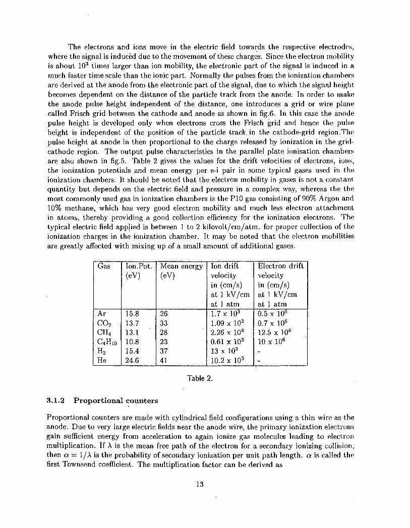
The electrons and ions move in the electric field towards the respective electrodes,where the signal is induced due to the movement of these charges. Since the electron mobilityis about 103 times larger than ion mobility, the electronic part of the signal is induced in amuch faster time scale than the ionic part. Normally the pulses from the ionization chambersare derived at the anode from the electronic part of the signal, due to which the signal heightbecomes dependent on the distance of the particle track from the anode. In order to makethe anode pulse height independent of the distance, one introduces a grid or wire planecalled Frisch grid between the cathode and anode as shown in fig.6. In this case the anodepulse height is developed only when electrons cross the Frisch grid and hence the pulseheight is independent of the position of the particle track, in the cathode-grid region.Thepulse height at anode in then proportional to the charge released by ionization in the grid-cathode region. The output pulse characteristics in the parallel plate ionisation chambersare also shown in fig.5. Table 2 gives the values for the drift velocities of electrons, ions,the ionization potentials and mean energy per e-i pair in some typical gases used in theionization chambers. It should be noted that the electron mobility in gases is not a constantquantity but depends on the electric field and pressure in a complex way, whereas the themost commonly used gas in ionization chambers is the P10 gas consisting of 90% Argon and10% methane, which has very good electron mobility and much less electron attachmentin atoms, thereby providing a good collection efficiency for the ionization electrons. Thetypical electric field applied is between 1 to 2 kilovolt/cm/atm. for proper collection of theionization charges in the ionization chamber. It may be noted that the electron mobiliti&sare greatly affected with mixing up of a small amount of additional gases.
Gas
Ar
co2CH4
C4H10H2
He
Ion. Pot.(eV)
15.813.713.110.815.424.6
Mean energy(eV)
263328233741
Ion driftvelocityin (cm/s)at 1 kV/cmat 1 atm1.7 x 103
1.09 x 10³
2.26 x 10³
0.61 x 10³
13 x 103
10.2 x 10³
Electron driftvelocityin (cm/s)at 1 kV/cmat 1 atm0.5 x 10°0.7 xlO6
12.5 x 10⁶
10 x 106
--
Table 2.
3.1.2 Proportional counters
Proportional counters are made with cylindrical field configurations using a thin wire as theanode. Due to very large electric fields near the anode wire, the primary ionization electronsgain sufficient energy from acceleration to again ionize gas molecules leading to electronmultiplication. If A is the mean free path of the electron for a secondary ionizing collision,then a = I/A is the probability of secondary ionization per unit path length, a is called thefirst Townsend coefficient. The multiplication factor can be derived as
13

M = — = exp( r a{x)dx) (27)
where x is the position of the charge in the counter.
The dependence of o on x comes through the E/p dependence and empirical expressionsfor the dependence of a -on E/p have been given in literature :
a = A exp(-B/(E/p)) (28)
where E and p are the electric field and gas pressure. Normally M is limited to < 108,after which electrical breakdown in gas occurs.
In a cylindrical proportional counter with the anode wire radius of a, and chamberradius, b, the induced voltages from electrons and ions at the anode can be written as
l i ± £ 0 ) ( 2 9 )2-xd v a '
~-M—^—) (30)2ixd a + x0
where q is the total charge released by ionization, 1 is the length of the chamber andis the distance from the wire at which the charges are produced.
The total voltage tV = V~+V+ = -q/(lC)where C = In £ is the capacitance of the chamber per unit length.
The ratio of the contributions from electrons and ions to the total pulse height is
V-
since typically, a = lO/zra, b = 10mm and XQ = l//m, the value of V"/V+ is 0.01.This means that the major contribution to the signal at the anode comes due to movementof positive ions in a cylindrical proportional counter.
The time development of the signal is given by
* i ; ) (32)
where *0 =
Vo is applied voltage, \i is the ion mobility, P is the gas pressure in the counter. Dueto low ion mobility, the signal rises slowly and in typical cases, it may take hundreds ofmicroseconds to collect the full signal. However, one applies a short shaping time constantof the signal to derive pulses of microseconds duration.
14

3.1.3 Multiwire proportional chamber
A multiwire proportional chamber consists essentially of a set of thin, parallel and equallyspaced abode wires, sandwiched between two cathode planes (fig-6). The gap,l, betweenanode and cathode is normally three to four times larger than the wire spacings. The voltagesare applied in cathode and anode to operate the chamber in the proportional region. It wasshown by Charpak and collaborators [4] that a multiwire proportional counter essentially actsas a set of independent proportional counters for each wire. Thus by locating the avalancheposition by appropriate wire readout, it is possible to determine the position of interactionof the particle in the detector. The wire position readout is achieved electronically by any ofthe following methods : (i) delay line method, (ii) resistive method (iii) multiple samplingmethod. These type of chambers have been used extensively as position sensitive detectorsfor heavy ion research.
Y-Pos
X-Pos
50
100KQ 10MQ.
Y-Pos
I—3 5
-HV
50
Timing Signal
Figure 6: Multi-wire Proportional Counter
More detailed discussion on the multiwire proportional chambers and other types ofgas detectors such as drift chambers, time projection chambers and cathode strip detectors
15
is beyond the scope of this article and the reader is referred to a large number of reviewpapers and books that exist on this subject [5, 6, 7, 8].
3.2 Scintillation detectors
Certain materials when struck by a nuclear particle or radiation emit a small flash of lighti.e. scintillation in a suitable wavelength region. Zinc sulphide as a scintillator in the visi-ble wavelength region was used in the early periods of nuclear radiation studies. With thedevelopment of the photomultiplier tube by Curran and Baker [9] in 1944, the interest inscintillation detectors was resuscitated. Scintillators have many desirable general character-istics : (i) linearity to energy, (ii) fast time response, (iii) pulse shape discrimination and (iv)variety in materials (organic and inorganic types) etc. The light emission from scintillatorscan be characterised by the expression
) + B ( — ) (33)r
where TJ and rs are the fast and slow components and A,B are given by a functionalform
A = Nof(a,t) (34)
/(a , t) being of a Gaussian shape. The ratio of the fast and slow components dependson the scintillator material and the type of radiation interacting with it. This propertyof certain scintillators for the dependence of the ratio of fast and slow components on theparticle type helps in the identification of the nature of radiation by using the pulse shapediscrimination techniques.
There are six types of scintillator materials namely : (i) organic crystals, (ii) organicsliquids,, (iii) organic gases, (iv) inorganic crystals, (v) inorganic gases and (vi) inorganicglasses. We describe briefly below the main principles of the scintillation mechanism in theorganic and inorganic materials and discuss the properties of some of the commonly usedscintillation detectors for nuclear radiation detection.
3.2.1 Organic scintillators
These are aromatic hydrocarbon compounds containing linked or condensed benzene-ringstructures. Scintillation arises from transitions made by free valence electrons of the molecules.These delocalised electrons are not associated with any particular atom in the molecule andoccupy what are known as the 7r-molecular orbitals, consisting of spin singlet and spin tripletstates as shown in fig.7. Molecules excited to higher excited states degrade to S\ state with-out emission of light within < 10 ps (internal degradation). From S\, there is high probabilityof radiative transition to So states within a few nanoseconds time (fast component). Thetriplet states in a similar manner degrade to To state by internal degradation, which thende-excites to So indirectly through multiple collision process
16

To 4- To —> S* + So+phonons
and light comes after a delay time, which is characteristic of the interaction betweenthe excited molecules (slow component) in the scintillator.
= T
absorption
So
Internal' | degradation
fluoresectmce ^otriplet state
Singlet States
Figure 7: Deexcitation process in Organic Scintillators
Because of the molecular nature of the scintillation, the organic scintillators can beused in many physical forms such as crystals, liquids, plastics etc., without loss of scin-tillating properties. However, presence of small amounts of impurities can affect the lightoutput significantly due to quenching. The scintillation efficiency is defined as the fractionof deposited energy that appears in the form of light radiation. The absolute efficiency ofeven the best organic scintillators is quite low (3.5% for anthracene, CuHi0 as compared to7% for Nal).
a. Organic crystals
Table 3 gives some of the properties of the organic crystals employed for radiationdetection.
CrystalAnthracene, (CH ^ o )Trans-stilbene,(Ci4/7i2)Naphthalene, (Cw H6)p,p'- quarterphenyl
decay time30 nsec4-5 nsecfew nsec7.5 nsec
light output100% (normalised)50% - 75%30% - 40%90%
Table 3.
The main drawback in the organic crystals is the anisotropic response due to chan-nelling effects.
b. Organic liquids
17

The organic liquid scintillators are made by dissolving the scintillation solute in anorganic solvent liquid. Ionisation energy is absorbed mainly in the solvent and then passedon to the scintillating solute. The solvents commonly used are : xylene, toluene, benzene,phenylcyclohexane, triethylbenzene and decaline etc. The organic scintillator solutes are :
p - Terphenyl (CISHU)
PBD (2-phenyl, 5,(4~biphenyl) - 1,3,4 - Oxadiazole) (C2HUN2O)
PPO (2,5-diphenyl oxazole) (Cl5HnNO)
POPOP (l,4-Bis-[2-(5-phenyloxazolyl)] - benzene) {C-uHX6N2O'i)
The efficiency of liquid scintillators increases with solute concentration before reachinga broad maximum before saturation of solution takes place. Typical concentrations are 3gm of solute per litre of solvent. The scintillation decay times are typically 3 to 4 nsec. Theadvantages of the liquid scintillators are the following:
i) possibility of loading of other elements for specific detector applications: 6Li, Gd,11B for neutron and Sn, Pb for 7-rays
ii) loading of wavelength shifters for matching to PM tube
iii) pulse shape discrimination due to different response for different ionising particles.
The disadvantages are that the light output is extremely sensitive to impurities, suchas dissolved oxygen and other elements. Normally oxygen can be removed bubbling dry N%gas. Quenching due to loaded impurities can be minimized by adding naphthalene, biphenyletc. to the solvent.
c. Plastics
These types of organic scintillators are most widely used due to their flexibility inmachining, robustness, size and thickness. Plastic scintillators are also solutions of organicscintillators in a solid plastic solvent such as polyvinyltoluene (PVT), polyphenylbenzene(PPB) and polystyrene . The primary solutes are PBD and p-terphenyl (~ 10gm/l) andsecondary solute is POPOP which is used for wavelength shifting to match with PM tuberesponse. The typical scintillation decay times are in the range of 1-3 nsec in most plasticscintillators, which makes them quite suitable for fast timing applications.
18

3.2.2 Inorganic scintillators
Certain halides, fluorides and oxides containing sometimes small amounts of activator im-purities act as scintillators. The spectrum of the emitted light is in the range of 200nm- 600nm. In general, inorganic scintillators are 2-3 orders of magnitude slower in responsethan organic scintillators due to phosphorescence (GsF, however, has a fast decay time of ~ 5nsec). Major disadvantage for some inorganic scintillators is hygroscopicity. The advantageof inorganic scintillators over organic scintillators is the greater stopping power to gammarays due to their higher density and higher atomic number.
The scintillation mechanism in inorganic crystals is characteristic of the electronicband structure transitions. The doping of impurities helps in shifting the wavelength oflight emission to the suitable range for matching to the response of the photomultipHertubes. The light output response varies from scintillator to scintillator, and also depends onthe type of particles causing the ionisation. In certain scintillators, there is a slow and fastcomponent, whose relative magnitude depends on the density of primary ionization. Thisproperty has been exploited to carry out particle identification by pulse shape discriminationtechnique. The characteristics of various types of inorganic scintillators developed for nuclearparticle detection have been listed in table 4. Certain high Z oxide based scintillators suchas BGO, CdWO4 etc. have been recently developed and have very good stopping powerto gamma rays due to their high densities. The light output decides the energy resolutionachievable with different types of scintillators. Depending on the applications with regardto the requirements of energy and timing resolutions, counting rates, detection efficiencyand particle identification by pulse shape discrimination, one can select the type of detectormaterial best suited for a particular experimental set up.
Detectormaterial
Nal(Tl)CsI(Tl)Csl(pure)
Lil(Eu)CaF2(Eu)BaF2
CeF2
GSO{Gd2SiO5; Ce)BGO{BiAGezOX2)ZnWC-4CdWO 4
Density(gm/cc)
3.674.534.53
4.083.194.9
6.166.71
7.13
7.877.90
Decaytime(nsec)23010002.2-20100014009400.6620
.560
300
50005000
Wavelengthof emission(nm)415550305
: 400480435220310310430
480
480540
Lightyield(%)100856
355020
5-1020
12
2640
Hygroscopic
Yesslightslight
yesnono
nono
no
nono
Table 4.
19

3.3 Semiconductor detectors
Development of these detectors were started during 1950s and these detectors became com-mercially available in 1960s. Due to certain desirable features such as good energy resolution,higher density compared to gas and good time response, these detectors are increasingly be-ing used for nuclear spectroscopy applications. The most common semiconductor detectorsare made of silicon and germanium. The band gap in these materials are l.leV and 0.7eVrespectively, which governs the amount of energy required to create an electron-hole pair.Silicon detectors are better suited for room temperature applications for charged particledetection, whereas germanium detectors are preferably used at LN2 temperature for gammaray detection purpose.
The detectors are made by having a semiconductor with np junction and by applyingthe operating voltage in the reverse bias mode. In this mode, a.depletion zone is formedwhich is free of charge carriers and possesses a linearly varying electric field as shown in fig.8.The depletion depth depends on the concentration of n and p impurities and the appliedvoltage.
Time
Figure 8: Signal pulse shape in a np junction
In terms of resistivity of the bulk material, one can write the relationship for thedepletion depth as a function of applied reverse bias voltage as follows :
d = O.53(/9nVo)2 //m, for Si n-type
) f° r Si p-type
The junction capacitance can be calculated as follows
20

C = 2.2(pnV0)-2 pF/mm2, for Si n-type
"= 3.7(ppVo)"2 pF/mm2, for Si p-type
The energy resolution achievable with Si-semiconductor detectors is again decided byw, the average energy required to produce an electron-hole pair, which is about 3.62 eVat T= 300°K. By using the Fano factor of 0.12, one can see that for 5 MeV a-particles,the FWHM is about 3.5 keV due to statistical spread in the e-h production. The observedenergy resolution is ,however, dominated by the electronic noise of the pulse processing mod-ules and one normally gets typical resolutions of 20-25 keV for the semiconductor detectorsat room temperature. There are various types of detectors made for charged particle spec-troscopy applications, depending on the method of creating the semiconductor junction andthe depletion zone. These are :
i) Diffused junction : The junction is made by diffusing n and p type impurities fromthe two sides. The concentrations of n- and p-types are controlled to provide the suitabledepletion layer containing the electric field for collection of ionisation charges due to incidentradiation.
ii) Surface barrier: The junction is formed by evaporating a metal on a semiconductor.The barrier so formed is called Schottky barrier. For n-type Si, gold provides the surfacebarrier junction, whereas for p-type Si, aluminium provides the surface barrier junction.
iii) Ion implanted diode : In this case the impurity atoms are implanted into the siliconcrystal with a low energy (50-100 keV) ion implanter. Both boron and phosphorous atomscan be used for n-type and p-type materials to provide the junction.
iv) Li-drifted Si-diode or Si(Li) detector : This is based on the compensation of theimpurities of the base material, to provide large thickness for the depletion zone. Largeintrinsic layer thicknesses of 3-5 mm can be achieved by this process. Such detectors arewidely used for x-ray detection in the energy range of 1-100 keV, after cooling the detectorand the first FET stage of the preamplifier to liquid nitrogen temperature. In this way,energy resolutions of 150-200 eV can be achieved for 5.9 keV 55Fe X-rays to carry out highresolution energy dispersive x-ray measurements.
v) High purity germanium detectors : For gamma ray detection, germanium is pre-ferred over silicon due to its much higher atomic number. In order to obtain a sufficientsensitive thickness for detection of high energy gamma rays, earlier the detectors were madefrom lithium compensated p-type germanium. However, these detectors have to be keptcontinuously cooled at liquid N2 temperature, due to high mobility of Li ions in germaniumat room temperature. Recently, it has been possible to grow germanium crystals with veryhigh purity such that the impurity concentrations are less than 1010 atoms/cc. Detectorsmade out of such crystals do not need any Li compensation and are called high purity germa-nium detectors. One advantage of this is the possibility of using n-type germanium, where
21
a very thin window can be formed by ion implantation to extend the sensitivity to very lowenergy gamma rays. Presently, Ge detectors are available with large volume crystals havinggood photopeak efficiency for MeV gamma rays. However, in order to further reduce theCompton scattered background from the gamma ray spectra, one employs a scintillationbased Compton shield around the Ge detector, which is operated in anti-coincidence modewith the Ge detector. Such Compton suppressed high purity Germanium detectors are usedextensively for high resolution spectroscopic studies in nuclear physics research.
As one can see from above, semiconductor detectors are available in wide varieties forenergy spectroscopy of charged particles and gamma rays. More recently, due to advancesin silicon processing technology, very high resolution position sensitive detectors are beingmade which can provide position resolution in micron range for particle tracking in highenergy physics experiments [10].
4 Cherenkov Radiation and Cherenkov Counters
Cherenkov radiation occurs when the velocity of a charged particle traversing a materialmedium exceeds the velocity of light in that medium. The cherenkov photons are emittedat a fixed angle, which is decided by the velocity of the particle and the refractive index, nof the medium as
The velocity threshold for Cherenkov radiation in a medium is, therefore, 0th — £• ft m a v
be noted that for a given medium, n is a function of wavelength A as well as temperature ofthe medium.
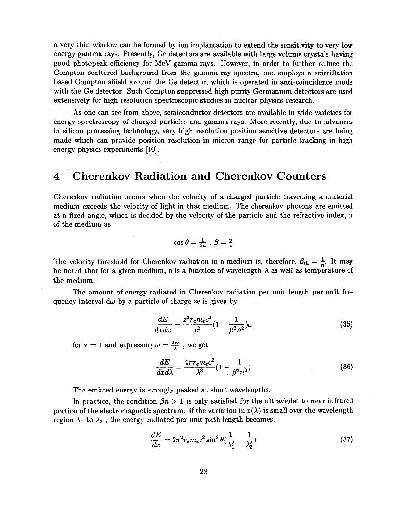
The amount of energy radiated in Cherenkov radiation per unit length per unit fre-quency interval du by a particle of charge ze is given by
dE z2reme(? 1 , ,(! ) w (3 5)dxdco c2 /?2n
for z = 1 and expressing u) = ^ p , we get
The emitted energy is strongly peaked at short wavelengths.
In practice, the condition f3n > 1 is only satisfied for the ultraviolet to near infraredportion of the electromagnetic spectrum. If the variation in n(A) is small over the wavelengthregion Ai to A2 , the energy radiated per unit path length becomes,
~ = 27r2remec2 sin2 0(1- - ~ ) (37)
uX Ai A<i
22
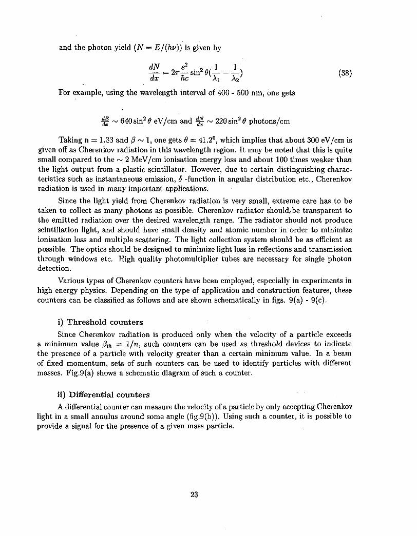
and the photon yield (N — EJ{hv)) is given by
^ 1 1^ = 2 ^ sin2 0 (1-1) (38)dx he Ai A2
For example, using the wavelength interval of 400 - 500 nm, one gets
% ~ 640 sin2 0 eV/cm and g ~ 220 sin2 0 photons/cm
Taking n = 1.33 and 0 ~ 1, one gets 9 = 41.2°, which implies that about 300 eV/cm isgiven off as Cherenkov radiation in this wavelength region. It may be noted that this is quitesmall compared to the ~ 2 MeV/cm ionisation energy loss and about 100 times weaker thanthe light output from a plastic scintillator. However, due to certain distinguishing charac-teristics such as instantaneous emission, 8 -function in angular distribution etc., Cherenkovradiation is used in many important applications.
Since the light yield from Cherenkov radiation is very small, extreme care has to betaken to collect as many photons as possible. Cherenkov radiator should,.be transparent tothe emitted radiation over the desired wavelength range. The radiator should not producescintillation light, and should have small density and atomic number in order to minimizeionisation loss and multiple scattering. The light collection system should be as efficient aspossible. The optics should be designed to minimize light loss in reflections and transmissionthrough windows etc. High quality photomultiplier tubes are necessary for single photondetection.
Various types of Cherenkov counters have been employed, especially in experiments inhigh energy physics. Depending on the type of application and construction features, thesecounters can be classified as follows and are shown schematically in figs. 9(a) - 9(c).
i) Threshold counters
Since Cherenkov radiation is produced only when the velocity of a particle exceedsa minimum value /?^ = 1/n, such counters can be used as threshold devices to indicatethe presence of a particle with velocity greater than a certain minimum value. In a beamof fixed momentum, sets of such counters can be used to identify particles with differentmasses. Fig.9(a) shows a schematic diagram of such a counter.
ii) Differential counters
A differential counter can measure the velocity of a particle by only accepting Cherenkovlight in a small annulus around some angle (fig.9(b)). Using such a counter, it is possible toprovide a signal for the presence of a given mass particle.
23
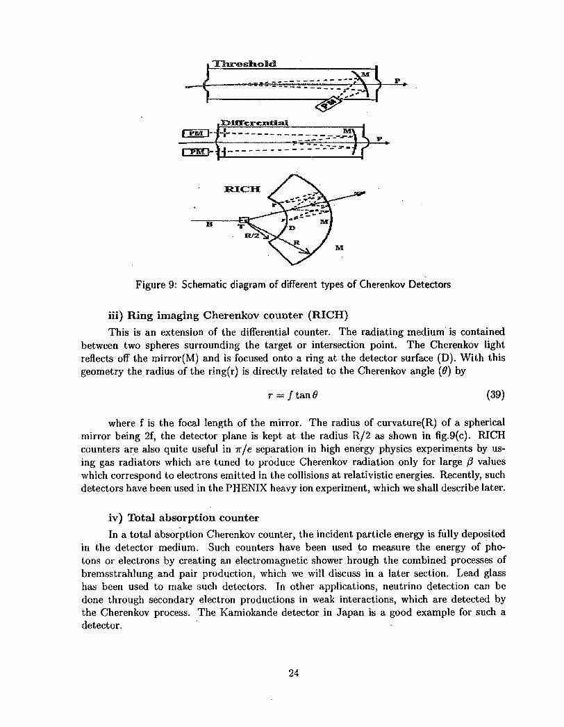
Figure 9: Schematic diagram of different types of Cherenkov Detectors
iii) Ring imaging Cherenkov counter (RICH)
This is an extension of the differential counter. The radiating medium is containedbetween two spheres surrounding the target or intersection point. The Cherenkov lightreflects off the mirror(M) and is focused onto a ring at the detector surface (D). With thisgeometry the radius of the ring(r) is directly related to the Cherenkov angle (0) by
r = / tan 6 (39)
where f is the focal length of the mirror. The radius of curvature(R) of a sphericalmirror being 2f, the detector plane is kept at the radius R/2 as shown in fig.9(c). RICHcounters are also quite useful in 7r/e separation in high energy physics experiments by us-ing gas radiators which are tuned to produce Cherenkov radiation only for large /? valueswhich correspond to electrons emitted in the collisions at relativistic energies. Recently, suchdetectors have been used in the PHENIX heavy ion experiment, which we shall describe later.
iv) Total absorption counter
In a total absorption Cherenkov counter, the incident particle energy is fully depositedin the detector medium. Such counters have been used to measure the energy of pho-tons or electrons by creating an electromagnetic shower hrough the combined processes ofbremsstrahlung and pair production, which we will discuss in a later section. Lead glasshas been used to make such detectors. In other applications, neutrino detection can bedone through secondary electron productions in weak interactions, which are detected bythe Cherenkov process. The Kamiokande detector in Japan is a good example for such adetector.
24

5 Electromagnetic Calorimeters
For high energy photons (Ey > a few tens of MeV), the major interaction in a detectormedium is by pair production and for electrons with similar energy bremsstrahlung processis the dominant mode of energy loss. In both these processes, the initial energy of the photonor the particle gets reduced on the average by a factor of two after each interaction. Thesetwo processes continue alternately producing an electromagnetic shower. The length of ashower depends on the initial energy of the photon and can be calculated in an approximatemanner as follows:
UCeV14CeV12 C«V10 G«V
C<V6CV
4CV
2 G.V
0 2 4 6 8 10 12 14 16 18 20DEPTH IN LEAD ( radiation length)
Figure 10: Longitudinal profile of e.m. shower
Let EQ be the initial energy. After one radiation l eng th , ^ the photon qn an averagegets converted to an e+, e~ pair each having energy EQ/2. After two XR, the e+ , e~ will eachemit a bremsstrahlung photon with approximately half the energy of the charged particle.After t radiation lengths, total number of particles (photons, e+ and e~) will be N « 2' withaverage energy E PZ E^j1t. If we assume that shower stops at the critical energy Ec, then
E(tmax) — Ec —Ep (40)
25

or
*•*- = Tit-and
^- (42)
In reality, the number of particles in an e+, e ,7 cascade rises exponentially to a broadmaximum after which it declines gradually as shown in fig.10. Empirical fits to the MonteCarlo simulations for the shower profile yield the following relations for the shower pathlength and number of particles at the shower maximum.
s
Nmax = 8.46 < 9 3 5 (44)
The longitudinal development of electromagnetic showers in different materials is foundto scale if the distances are measured in radiation lengths.
Another quantity of interest in an e.m. shower is the shower radius. The radius withinwhich 90% of the shower particles are contained at each depth is called the "Moliere Ra-dius", which is approximately given by p ~ 7A/Z g/cm2. Roughly, 95% of the shower iscontained laterally in a cylinder with radius 2pm. The transverse shower profile as a functionof shower depth clearly exhibits rather pronounced central and energetic core surrounded bya low energy halo.
An electromagnetic calorimeter can be conceptually thought to be a block of matterthat is of sufficient thickness to cause an interacting particle deposit all its energy insideits volume. A fraction of the deposited energy is detectable in the form of a more practicalsignal (e.g. scintillation, Cherenkov light or ionisation charge etc.), which is proportionalto the initial energy. The uncertainty in the energy measurement is governed by statisticalfluctuation in the average number of secondary particles. Hence,
I ^ L (45)The length of the detector to stop particles of energy E increases logarithmically with
particle energy.
There are two types of calorimeters : a) homogeneous and b) sampling. The homoge-neous calorimeters are made by large volume detectors of single type. For very high energyparticles, sampling calorimeters are usually employed, which consist of alternate layers ofhigh-Z converter material and low-Z detector material. A small fraction of the shower energyis sampled. The advantages of sampling calorimeters are i) possibility of both longitudinaland lateral segmentation ii) economy of detector size and iii) low cost. The factors whichaffect the energy resolution in the sampling electromagnetic calorimeters are i) leakage ofthe shower ii) sampling fluctuations iii) Landau fluctuations and iv) path length fluctuations.
26
Given sufficiently fine grained instrumental resolution , the localisation of the centreof gravity of the transverse distribution of the shower profile can be achieved by samplingthe initial part of the shower.
6 Particle identification techniques
One of the important requirements of a detector setup is to identify the type of particlesentering the detector medium. Various methods have been employed depending on the par-ticle type and energy range to be investigated and on the requirement for the resolutionwith which they have to be measured. These methods are broadly based on the followingprinciples,i) Energy lossii) Pulse shape analysisiii) Time of flightiv) Magnetic spectrometry
As we have seen earlier, the energy loss of a charged particle in a detector medium canbe written as
AE a Mf (46)
where M, Z and E are the mass, charge and energy of the particle. If one measuressimultaneously the E and AE of the particle, one can derive the information on the productMZ2 of the particle. This method is widely employed for identification of light and mediumheavy nuclei produced in nuclear collisions. The AE and E of the particle can be measuredby employing a detector telescope consisting of a thin detector followed by a thick detectorto completely stop the particle. The two detectors can be combination of any of the typessuch as gas, semiconductor and scintillation detectors. In some situations, two scintillationdetectors having different decay times are used in sandwich geometry and are read out by asingle photomultiplier tube. By selecting suitable integration times for the observed signal,it is possible to derive the AE, E information from such a device. This type of assembly isknown as phoswich detector assembly and has been used in many experimental setups forcharged particle spectroscopy studies.
Another method of particle identification is the pulse shape analysis from a singledetector. As mentioned above, many scintillators have both slow and fast decay times ofthe scintillation ionisation density in the detector medium. The inorganic scintillators, Csl,BaF2, Nal and certain types of organic scintillators such as NE213 possess this property.Recently, the rise time differences in the pulse formation in semiconductor detectors havealso been exploited to carry out particle identification by pulse shape analysis. It has beenshown that by allowing particles to enter from the ohmic contact side improves the quality ofpulse shape discrimination in these detectors. An example of the pulse shape discriminationwith silicon AE detectors is shown in fig.ll. This principle has been exploited in makinglarge detector setups for various experimental studies. One major experimental facility usingthe PSD principle for silicon detectors is the 8vr LP detector array set up at the Legnaro
27

National Laboratory in Italy. This detector array consists of 262 AE - E telescopes arrangedaround the target to cover 90% of 4ir for detection of light cahrged particles. More detailsof this set up can be found in ref [11].
192
232Th at 60MeV,
128 192 256E (MtY)
Figure 11: Pulse shape Vs Energy in a Surface Barrier Detector
The time of flight method for particle identification uses the relations
(47)
By measuring the energy and time of flight, one can determine the mass of the par-ticle entering the detector. This method has been also used extensively for neutron energy
' measurements using- fast liquid scintillators, where gamma-neutron discrimination is carriedout by pulse shape analysis and neutron energy is determined from the time of flight of theneutrons.
In magnetic spectrometry, the particles are made to traverse in a magnetic field. Thedeflection in the trajectories of the particles depends on their momentum. In a uniform field,one can use the relations
p — mv = Bqp (48)
28

and
(49)
By simultaneous measurement of energy and radius of curvature ,p one can derive theinformation on the mass of the particle. However, in a non-uniform magnetic field, one needsto integrate the above expression to determine the deflection of the particle as function of itsmomentum. These different methods have been employed in suitable combinations to carryout particle identification and energy measurements in various detector setups. A review onthe charged particle detector arrays built in different accelerator laboratories can be foundin ref [12].
In the following section, we shall briefly describe one of the most advanced and complexdetectors(PHENIX) being set up for heavy ion collisions at relativistic energies at the RHICaccelerator at BNL, USA. This detector provides a good example as to how different detectionprinciples are employed to carry out the measurements in an environment of very highparticle multiplicities produced in relativistic heavy ion collisions.
7 PHENIX Detector
The PHENIX detector is being set up at the Relativistic Heavy Ion Collider (RHIC) at BNL,USA to study the p-p, p-A and A-A collisions upto few hundred GeV/n centre of mass energy.The RHIC accelerator, when operational by the middle of 1999, will be the highest energyaccelerator for heavy ions and will be used to investigate the possibility of the phase transitionof normal nuclear matter to quark gluon plasma at extremely high temperatures and matterdensities. The signatures for such a phase transition have been predicted theoretically interms of changes in the properties of vector mesons (p, u, <f>, J/ifi, ip' etc), enhancement in theproduction of strange and charm particles, particle correlations and changes in the ratio of theyields of various baryons and mesons etc. The PHENIX (Pioneering Heavy ion InteractionExperiment) experiment has been designed to measure with good efficiency and resolution,these various quantities in the high multiplicity environment of the heavy ion collisions atthe relativistic energies. The PHENIX detector consists of detector elements to measure theleptons (e+, e~, /x+, n~) ,which are emitted as decay products of the primary particles as wellas photons and hadrons produced during the collision process. Fig. 12 shows the layout ofthe PHENIX detector. This consists of two central electron arms and two end to end muonarms. Apart from these detectors, there are inner detectors such as beam-beam countersalong the beam pipe and silicon vertex detectors arranged around the collision point. Themomentum dispersion of the particles is done by the central magnet having field in axialdirection and the muon magnets having field along radial direction. In the following, wegive a description of the salient features of the different detector elements of the PHENIXdetector.
29
7.1 Inner Detectors:
7.1.1 Beam-Beam counters:
The two sets of beam-beam counters are arranged along the beam axis symmetrically oneither side of the beam collision region. The counters are made of Pb-Glass Cherenkovdetectors, which provide very fast timing signals and enable the determination of the space-time location of the collision point for first level trigger purpose. A position resolution ofabout 2 cm in z-direction of the collision point is achieved by these detectors. The timingresolution is obtained as 60-80 picosec by using very fast photo-multiplier tubes to detectthe Cherenkov radiation from the BBC detectors.
7.1.2 Vertex Detectors:
This consists of three layers of thin microstrip detectors having very large granularity andgood position resolution. The radiation length of these detectors is very small and is notsufficient to initiate e-tn showers for the electrons and photons. The particle tracks generatedout of the hits in these detectors are extrapolated into the collision region to reconstruct thevertex location to an accuracy of about 100-200 microns. Such a precise determination ofthe collision vertex improves the momentum resolution of the particle tracks in the trackingdetectors.
7.2 Electron Arm :
The electron arms consist of a number of gas tracking detectors of drift chamber and padchamber design to construct the particle tracks, and at the end the electro-magnetic calorime-ters are placed to determine the total energy of the particles. There are also ring imagingCherenkov counters, which are highly useful to discriminate electrons from the hadrons.RICH detectors play a key role as trigger detectors in PHENIX experiment since they caneffectively eliminate the large background of pions with about 104 :1 ratio, thereby providinga clean set of signals for the electrons and photons. With the combination of momentumfrom the tracking detectors and total energy from electromagnetic calorimeters, one canidentify the electrons from other type of particles. The e-m calorimeters in the PHENIXdetector are mainly of sampling type which are highly segmented to determine the locationof the interaction point. The particle tracks generated in the tracking detectors are con-nected with the e-m calorimeter to correlate their signals. The electron arms also contain asmall coverage for detecting hadrons like pions, kaons etc through the use of time of flightdetectors. These detectors are made of scintillator blocks, which are coupled to PM tubes forgiving the time of interaction. By combining the time of flight and momentum information,the mass of hadrons are determined. Thus by a combination of varieties of detector types inthe electron arm, one is able to measure the very weak electron signals in the presence of alarge background of hadrons produced in the relativistic heavy ion collisions.
30
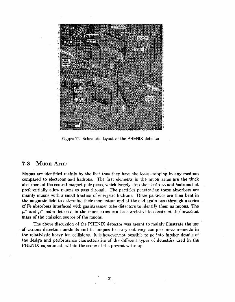
Figure 12: Schematic layout of the PHENIX detector
7.3 Muon Arm:
Muons are identified mainly by the fact that they have the least stopping in any mediumcompared to electrons and hadrons. The first elements in the muon arms are the thickabsorbers of the central magnet pole piece, which largely stop the electrons and hadrons butpreferentially allow muons to pass through. The particles penetrating these absorbers aremainly muons with a small fraction of energetic hadrons. These particles are then bent inthe magnetic field to determine their momentum and at the end again pass through a seriesof Fe absorbers interfaced with gas streamer tube detectors to identify them as mudns. The/i+ and n~ pairs detected in the muon arms can be correlated to construct the invariantmass of the emission source of the muons.
The above discussion of the PHENIX detector was meant to mainly illustrate the useof various detection methods and techniques to carry out very complex measurements inthe relativistic heavy ion collisions. It is,however,not possible to go into further details ofthe design and performance characteristics of the different types of detectors used in thePHENIX experiment, within the scope of the present write up.
31
8 Summary
This lecture series was aimed at providing a basic understanding of the detection principlesemployed in nuclear physics studies. Detectors are made by exploiting different aspects ofthe particle interactions in the medium. The modern detector systems are highly complexand modular, trying to achieve the ultimate performance in resolution and sensitivity. Apartfrom the detectors,it is also the signal processing electronics which go together to bring outthe best in the performance of the experimental setups.
We have not been able to touch upon the advances made in the electronics and dataprocessing systems that have taken place in the recent times. Also the wide range of positionsensitive detectors with wide range of applications in other areas of science could not becovered in the present lectures and the reader may refer to many books and review articlesavailable in the literature on these detectors.
References
[I] N.Bohr, Kgl.Danske Videnskab. Selskab, Mat. Fys. Medd. lj£(1948)8
[2] See S.Ahlen, Rev. Mod. Phys. 52(1980)121
[3] See H.A.Bathe and J.Ashkin, Passage of radiation through matter in E.Segre (Ed.)Experimental Nuclear Physics Vol.1, Part 2, New York, Wiley (1959)
[4] G.Charpak, R.Bouclier, T.Bressani,J.Favier and C.Zupanacic, Nucl. Instr. Meth.£2(1968)235
[5] G.Charpak and F.Sauli, Proc. Conf. on computer-assisted scanning, Padova,21-24April (1976), p 592
[6] F.Sauli /'Principles of operation of Multiwire Proportional and Drift Chambers",CERN Report 77-09 (1977)
[7] M.Atac and W.E.Taylor, Nucl. Inst. .& Meth. 120(1974)147
[8] K.Kleinknecht, "Particle Detectors" in Techniques and concepts of High EnergyPhysics, ed. by T.Ferbol (Plenum Press, New York 1981)
[9] J.M.Schonkeren, "Photomultipliers", Philips Application Book Series ed. H.Kater andL.J.Thompson (Philips Eindhoven, The Netherlands)(1970)
[10] B.Hyams, U.Koetz, E.Belau, R.Klanner, G.Lutz, E.Neugebarcer, A.Wylie andJ.Kemmer, Nucl. Inst. & Meth. 205(1983)99
[II] G.Prete, E.Fioretto, M.Cinausero, M.Giacchini, M.Lollo, D.Fabris, M.Lunardon,G.Nebbia, M.Caldogonom, A.Brondi, G.LaRana, R.Moro, E.Vardaci, A.Ordine,A.Zaghi, A.Boiano, P.Blasi, N.Gelli, F.Lucarelli, G.J.Yuan and B.K.Nayak, Nucl.Inst.& Meth. A422(19"99)263
32
[12] R.K.Choudhury , Proc. IV SERC school on Intermediate Energy Nuclear Physics,Goa, Ed. Y.K.Gambhir(1993)
33

Published by: Dr. Vijai Kumar, Head Library & Information Services DivisionBhabha Atomic Research Centre, Mumbai - 400 085, India.


