EXPERIMENTS OF THE STRENGTH OF BOLTS AND SCREWS BY JONATHAN HUNTOON SAMUELS HODGSON BERT ANDREW MILLER THESIS FOR THE DEGREE OF BACHELOR OF SCIENCE IN MECHANICAL ENGINEERING IN THE COLLEGE OF ENGINEERING OF THE UNIVERSITY OF ILLINOIS JUNE, 1910 */
Transcript
EXPERIM ENTS OF THE STRENGTH OF BOLTS AND SCREW S
BY
JONATH AN HUNTOON SAM U ELS HODGSON
B E R T AN D REW M ILLER
TH ESIS FOR THE DEGREE OF BACH ELOR OF SCIENCE
IN M ECH AN ICAL ENGINEERING
IN T H E
COLLEGE OF ENGINEERING
O F T H E
U N IV ER SITY OF ILLINOIS
JUNE, 1 9 1 0 ✓ */
UNIVERSITY OF ILLINOIS
May 31 1910 190
THIS IS TO CERTIFY THAT THE THESIS PREPARED UNDER MY SUPERVISION BY
Jonathan Huntoon Samuels Hodgson and Bert Andrew Miller.....
Experiments on the Strength of Bolts and Screws ENTITLED............................................................ .......
IS APPROVED BY ME AS FULFILLING THIS PART OF THE REQUIREMENTS FOR THE
Bachelor of Science in Meohanical EngineeringDEGREE OF----- -----------
h e a d OF DEPARTMENT OF....Mechanical Engineering
1 6 7 3 5 7
==ll
*********** t a b l e o p c o n t e n t s**********
Introduction......................... Page 1
Test Pieces and Testing*• ........... * 2
Data*............................... • • • " 6
Conclusions*........................... " 11
Tables................................. * 13
Photographs* ......................... * 16
Curves 21
1******* **INTRODlJCTION»********
In this oountry very little has been done on the strength of bolt threads. A. L. King made some experiments on the tensile strength of screw threads, an account of which appeared in the American Machinist of August 13th, 1896. His work was confined to comparison of different types of thread made by other methods, which was the plan followed out in this thesis. His results showed that; (1) when subjected to plain tension the different types of screw threads were stronger than the plain bars of the same area of cross section by about fourteen (14) per cent, (3) no very marked difference in the strength of the different styles of threads appeared; the perfectly sharp groove, being slightly stronger than the others which were grooves of round and flat bottoms, (3) the weakening effect of the turning of the nut under stress was in the one inch bolts twenty per cent, and in the one half inch, about fifteen per cent, (4) in general, it may be said that the turning of the nut upon the bolt at rupture reduces the strength of the net section thirty per cent.
The object of this work is to give the comparative strength of three different kinds of threads, viz: die-cut, machine-cut, and rolled, using bolts one half, three quarters, and one inch in size for each make of thread. The tests were to determine the strength of bolt in static tension and the shearing strength of the thread. All cut threads were U. S. Standard, and the rolled threads were as nearly like them as was possible to get them.
2The die and machine cut threads are the commonest
type of thread and, are most used in practice. The die-cut, since it is cheaper, is used where workmanship and cost enter into consideration, while the machine-cut thread is adapted to work where accuracy and smoothness are required, regardless of the cost of production. The rolled threads are made extensively for track bolts and rough work where the size of the shank does not make an appreciable difference. The general practice does not seem to take into account the strength of the rolled thread but simply the cheapness of the bolt and the adaptability to rolling the form of bolt required.
********TEST PIECES AND TESTING********The material for the bolts and threads of the die~and
machine-cut type was ordinary soft steel bought in the openmarket. The specimens were obtained from different bars and as
s t r d f l g l f j sa result the Ptydaocs were not the same in all cases. The stock, being cheap, was not uniform in size and it was due principally to this fact that the threads were not perfect in every case.The machine-cut threads were made as smooth as possible. No half-inch lathe cut bolts were tested on account of the difficulty in cutting so small a bolt in the lathe. The die-out threads were turned out in the thread cutting machine in the shops of The University of Illinois. The dies were not very sharp but were as good as would ordinarily be found in practice. The rolled threads were obtained from the Oliver Steel and Iron Co. of Pittsburg, Pa. The process in the manufacture seems to be the passing of heated stock between two dies that move in opposite directions and at the same speed, thus causing the stock to
5rotate but not to have translation. The threads are simply squeezed into shape by diagonal thread forming projections on the dies which works the material so that its strength is increased. The nuts cannot be rolled in the small sizes.
All of the specimens, except the rolled stock, were two feet long with each end threaded. One end was tested for tensile strength, the other for shearing strength of thread.The rolled stock was about eighteen inches in length with approximately the same number of threads. For the shearing tests the specimens were set up in a lathe and centred as true as possible. The threads were then turned off at the root except for about two whole threads. Calculations showed that under ordinary
T L a i v d L f r i M , t io J lw - Z Z b
stresses for mild steel that about sixteen hundredths of an inchA
was about all that would shear, while in the three quarters inch eighteen hundredths could be used, and for the one inch twenty- one one hundredths of an inch was necessary.
A system of classification of specimens was deemed0
necessary and the following was adapted. The identification mark gives the number of the specimen, diameter of the stook, and the kind of thread; as for instance, 2-5/4-M would mean specimen number two of the three-quarters inch machine cut thread. D and R were used for the die and rolled threads respectively. From the tabulated data it will be notioed that the one half inch die cut specimens begin with the number 4-1/2-D. This is because the first three specimens were discarded on account of the inaccuracy of the root diameter measurements. The anvils of the micrometer did not fit the V shaped thread. Thereafter an ordinary clamp caliper was used.
4Nearly all the tests were rade in a Riehle testing
machine, having a oapaoity of 100000 pounds. The tests were run at slow speed until the yield point was passed and then high -speed used till rupture occurred. little trouble was encountered with the eighteen inoh rolled specimens. The head of the machine was so thick that not enough material was left to allow for attaching the instruments. A head made of two and one quarter inch slabs of steel was fitted to a 100000 pound Philadelphia testing machine and this machine used for the tests of short bolts.
Two extensometers were used to get the extensions.They were of the wire-wound drum type, reading to ten-thousandths of an inch. The other instruments used were miorometer calipers for the shank of the bolt, thread calipers reading accurately up to one- hundredth of an inch, and some tools such as wrenohes and hammers for marking test pieces.
It was intended to get the elongation in the thread by the use of the two extensometers. One was to record the elongation in the known length of the shank and the other, the elongation in the part of the thread in tension and a part of the shank. Then knowing the elongation in inohes per inch from the first extensometer and the length of the shank above the second extens- ometer, the elongation in the thread could be calculated by subtracting the elongation in the shank from the total elongation as recorded by the second extensometer. This was very good intheory but the length of the thread in tension was so indefinite
resultsthatAas much as twenty five per cent too great or too small were possible since a part of the stress was in the nut as was plainly
5evidenoed on examination*
A description of the actual carrying out of a tension test will not be amiss here. The specimen was placed in the machine without the instruments and the space inside of which the recording apparatus was to be placed, was marked roughly with a piece of chalk. The root and thread diameters were measured and recorded. The stock or shank extensometer was set up in the jig whioh takes the length of stock of eight inches, and the bolt damped in. Then the second or thread extensometer was put on in the middle of the first with an ordinary damp. The test piece was then set in the machine and the nut turned on. A nickle steel washer was used between the head of the machine and the nut. This plate had two small holes drilled to permit passing a small wire over a lever fastened to the nut, for the operation of the thread extensometer. The lever and its attachments are shown in Pig. I. The lower extensometer marked I is the shank extensometer and the upper marked II is the thread extensometer. The length of shank from No. II up to the threads was measured and the lower head of the machine raised. The jaws were placed as high up as possible because of the threads on the lower end of the test piece. The bar was then aligned and a light load of about a hundred pounds put on it. The pointers were placed at zero and the test was begun, first by putting on about 1200 pounds, but after that, readings were taken at equal increments of elongation on the thread extensometer as far as the elastic limit. Readings of both extensoraeters and load were obtained, and after every third reading the strain was relieved when the extensometer release readings were taken. The instruments were taken off after the
6
elastic limit had been passed, and the load increased till rupture occurred.
In the shear tests no instruments were used because there did not seem to be any yield in the specimen, but a sudden failure. The thread diameter at the root and the length of the thread in shear were measured. The test was made on the end which had been previously prepared. The nut A, shown in figure II, was turned on till the threads to be sheared were well up in the nut. The exact position was varied in the different specimens. The bolt was then placed in the machine. The plate B acted as a washer and a head as in the tension test. The specimen was then aligned and the jaws C clamped on. The bolt was then loaded at slow speed while the poise was carefully adjusted so that any sign of yield could be noticed in the fall of the beam.
After the tension and shear tests had been pulled off, the ultimate strength of the bar was found except in the case of the rolled stook, where the bar ruptured in the tension test.For these it was necessary to drill a part of the material out of the thread and then set up the specimen as in the other ultimate tests. The part drilled out was as near the center as could be obtained with an ordinary center punch and drills.
fc*#********#*#*])^^****#^***** ******The data as compiled in Table I show£ the calculated
results for each specimen, and the averages for each classification. The blank spaces in the plate are where no definite values could be obtained from the curves. With a different selection of points on the curve this would probably not occur. There was
7some difficulty in getting the ultimate strength of the rolled threads as has been mentioned before and explained* but in the table the figures give the stress on the whole area of the root of the thread as oalculated from the reduced part under test•The results obtained are probably not widely different from what they would be if fracture had ocourred across the original area. The calculated results were used in finding the per cent strength for these threads which, in every oase, was greater than one hundred per cent.
The point of rupture in the machine and die out threads was about half way between the nut and the shank. This was not true of the rolled. They broke at the bottom of the drilled out portion. The rolled specimens were hard to handle in the ultimate tests on the threads on account of the difficulty of setting them up straight. In one case there was evidence of a little bending action. This may have been due partially to the poor bearing surface of the nut. This fact entered into the results of some of the other tests and was unavoidable.
The comparative strength of the root and shank of the thread is shown in Table II. Reduoing the load on the shank and on the thread, at the different events, to pounds per square inch shows that the stress on the smaller area is greater than that on the larger area of the shank. This seems to be an accepted fact for static tension tests. The difference in the stress on the area at the root of the thread and that on the shank is great- est for the rolled threads, the machine cut next, and the die cut least. From this, it seems that the lathe tool has something of the effect on the material that rolling has. The table also shows
8that in the oase of the rolled bolts the per cent strength is greatest at the ultimate, while for the die-and machine-out, the yield point shows the greatest per cent strength.
The shear tests brought out some important considerations in the design of nuts, including lock nuts. There is a minimum allowable thickness which may be sufficient to stand the strain on the bolt. If we assume a factor of safety of five under static loads, the following formula is derived:-
Thickness of nut
where T is the allowable stress in pounds on the bolt in tension, £> the allowable shearing stress in pounds per square inch, and Q the circumference of the root of the thread in inches. The nut must fit well in each case in order that this may hold good. Table No, III shows the thickness of the nut required to stand the strain of the threaded portion, except in the case of the rolled threads, where the threaded portion was stronger than the shank.
The efficiency of a bolt has been taken to mean the ratio of the load on the thread to the load on the shank of the bolt at the corresponding events. For instance the efficiency of a bolt at the yield point would be the ratio of the load on the thread at yield, determined from the curve, to that of the shank determined in a similar manner. It is concluded that the events on the stress-strain curves for the shank and thread are for the thread alone since the area of that section is smaller and any failure would appear in the threaded portion first. This is not exactly true of the rolled threads, but it has been assumed
9that the events on this curve were also true for the threaded part. The efficiency has been determined for each kind of thread at the elastic limit, yield point, and ultimate. Plate I gives the results of these calculations and shows that the relative per cent strengths of the rolled threads at ultimate, is much greater than the two others. The same is true of the other events. The efficiency of the one inch rolled was one hundred nineteen (119) per cent at the ultimate, while the die-and machine -cut were eighty three (83) and eighty four (84) per cent respectively.The per cent strength seems to increase with the diameter of the shank for the die and machine cut threads. This was the case in all but the machine-cut threads at yield, where it decreased slightly. In the rolled threads the one inch increased a little at the ultimate, but, for all other events on the different sizes, the curves ran about horizontal. These curves from plate I show that the rolled threads are by far stronger than the others, and that there is no choice as far as strength is concerned between the die and machine threads. The working of the metal increases the strength and this no doubt accounts for the high values in favor of the rolled threads.
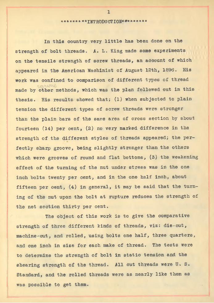
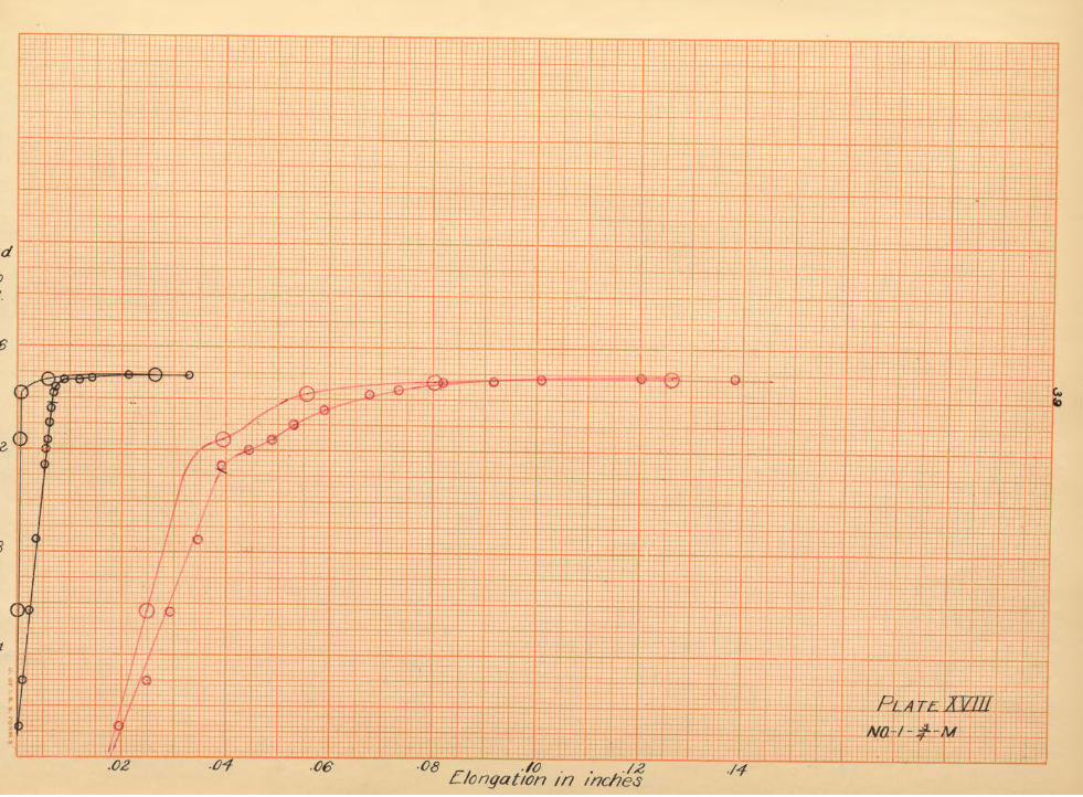
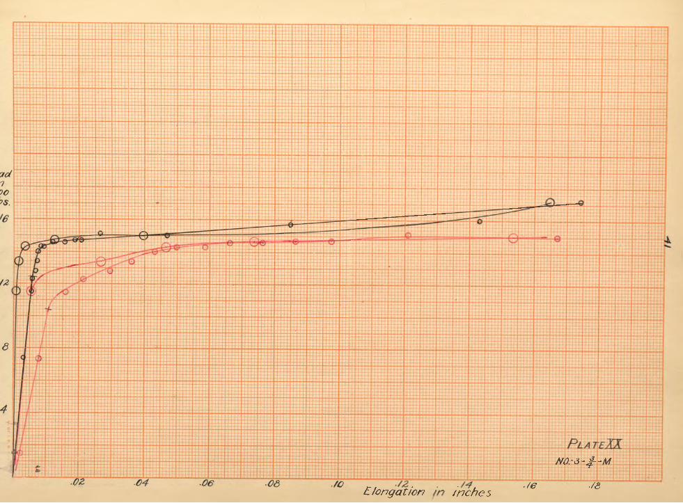
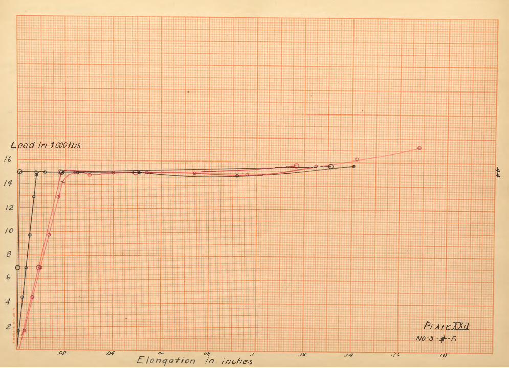
Plates No. Ill---XXXI are the load-elongation curvesfor each specimen that was tested. Each curve was plotted on a separate sheet to avoid confusion, and for the reason that the curves could not be reduced to the same basis since the areas and the lengths of the threads were not uniform. The latter could not be accurately determined. The ordinates were load in pounds and not in pounds per square inch, because the ratio of the loads was wanted at the events, and by plotting the curves as they are the
10
load can be read directly. The elongations were plotted as they were read. The points of release were plotted and show definitely where permanent set began.
Johnson's method was used in determining the elastic limit, in preference to the old way of assuming the elastic limit at the point where the curve broke away from the tangent. His method is as follows; take one half of the abscissa of any point on the straight line below the elastic limit and lay it off to the right from the ohosen point on the curve. A line drawn through this point to the intersection of the given straight line with the vertical through 0 determines the position of a second line parallel with the construction line and tangent to the curve. The point of tangenoy gives the elastio limit. This is shown better on Plate III where AB represents the length from the point to the ordinate, and BC, one half of this distance laid off to the right. CO is the line through the origin and this last determined point, and EF is the line parallel to OB tangent to the curve at the point G,- the elastic limit.
The yield point was taken at the point of inflection on the curve after the elastic limit had been passed. This is not a very acourate way to determine this point, but knowing that in tension tests of soft steel the curve is horizontal at what is called the yield, this method is considered sufficiently accurate for these tests. The ultimate was simply the maximum load on the specimen.
Plate II shows the ratio of areas at the root of the thread and the shank of the bolt for the three kinds of bolts.The curves show that the ratio for the die-and machine-cut bolts
11are practically the same, but the rolled threads are from nine hundredths to twelve hundredths nearer unity. The faot that the rolled thread is not sharp but of rounding section probably accounts for this high ratio. The fact that the curves for the rolled threads decrease, and the die-and machine-cut increase cannot be taken as of any consequence. The curves if carried farther would probably become horizontal.
********** CONCLUSIONS *********Prom the results obtained in this thesis the following
conclusions are drawn in regard to the kind of thread and their respective strengths:-
(1) The ratio of the area of cross section at the root of the thread to the area of the shank is practically a constant for the rolled threads and increases slightly for the die-and machine- cut threads as the size of the bolt increases.
(2) The efficiency of the rolled thread in tension is greatest at the ultimate, and is also greater than the machine or die cut threads at any event. This efficiency decreases as the size of the bolt increases. The efficiency of the machine and die cut threads is praotioaily the same, and increases as the size of the bolt increases.
(3) The die- and machine- cut threads will stand a greater load in shear on the threads than the specimens of rolled stock because of the loose fit of the nuts furnished with this stock.The rolled bolts are not adapted to the uses that machine bolts are put to, or to any work where a close fit of the shank is re- qui red.
(4) A thickness of nut of one half the diameter of the
12stock is all that is necessary to prevent shearing in the nut for the die-and machine-cut threads while for the rolled threads a thickness of three-fourths of the stock is required.
/3
SAMPLE DATA SHEET.
SPECIMEN 3 - 1 - D.Load Total Elong- At release to Remarks,in elong- ation 500 lbs.lbs. at ion in 8 Exten someterin in. in. of No. I No. II
bar inin.
1600 .0051 .0008 Diameter at root .84"4100 .0111 .0016 Diameter of stock 1.08800 .0154 .0030 .0119 .0004 Diameter of stock11200 .0205 .0041 after rupture .96116100 .0255 .0059 Diameter at root20600 .0302 .0075 .0198 . 0004 after rupture .6924200 .0391 .0082 Length from Ext. No. I24900 .0495 .0082 up to end of thread 9.224900 .0560 .0088 .0440 .0004 Nut fit snug.25200 .0630 .008925800 .0685 .009026200 .0745 .0092 .0610 .000426800 .0810 .009327400 .0870 .009827700 .0950 .0122 .0812 .0035 Scaled slightly at bottom.28100 .1034 .020827900 .1095 .035827700 .1165 .0541 .1018 .044828000 .1308 .086128100 .1465 .112028000 .1555 .1145 .1512 .104228100 .1855 .133928200 .2100 .162529200 .2605 .1321 .2500 .169529200 .2830 .184230100 .3070 .1882 Scaled all over.31300 .3438 .2380 .3245 .204238400 Ultimate of thread.35000 Rupture.
SPECIMEN 3 - 1 - D.In Shear.
16500 Ultimate Length in shear .2"Rupture not definite as failure Diameter at root ,84
wa;s gradual • Diameter of stock 1.0Sheared nut and bolt. Nut fit snugGood clean shear • Threads near middle of nut.
TA B LE. I
T —2 — 3 4Spec/- Diam-Diam >m e n eterctat root ■
<0* 3 No. shankin in.
of thread in in
1 47-D 495 4002 5 7 D 496 4/0 .3 6-i-D 5 0 5 4/0 .4 7-i-D 494 4/0 .5 6-i-D ■503 400 .6 9-i-D 5 04 410 .7 10-i-D 5 0 0 4106 Average 4996 407/ .9 H R 446 410 .10 2-t-R 444 410f l 3-i-R 450 40012 Average 4467 406713 I-7D .742 £20/4 2-7D 745 6 2 015 3-7D 7 4 5 6 2 0/6 47-D 748 .62017 5~7 740 .62018 AVER7440 6 2 0/9 1 /~7750 .6201 0 7 7 M 7 47 .6202/ 3-7/4 75/ 6 2 022 Average 7493 .6202 3 I-7 R ..692 .630 .2 4 2 -7 R 707 .6302 5 3 7 R 702 630 .26 Average 7003 .630 [27 l-l-D ■988 .84028 7 ID ■990 .840293-ID WOO 84030 Average .9927 .84031 l-l-M .992 8 4 0322-l-M .992 .8403 3 3 l-M 993 .84034 Average 9923 .8403 5 1 - I R .923 8 3 0
7885 .8285 .6980.6925 [6925 .6960/3300 6820 i ito o .6822.6830 12900 088542700 .697542200 68 9 7.828544350 7940
5800 6600 6900
shank 10470 35550 8400 56700
10900 i 8000 33700
14400[606044200/4080 L 8095
5 5 3 9 7 2 1 0 26600 .5539,7190 27000
1425014500/4450 U700
.5539.7060 553917/53 .5539.7/70 5 5 3 9 7170
Z6800
24000/8800
.5539
.5539
.5420
.5420
.5420
.7/5027/63.8125.8060
2680027800
5420 .8058
23400
91009650990095008580
960095509200
13100
13720/250Q
/335012800/3200/l500
2/500Z/00022500
2/40020200
22.50017400 23200
7990 2300022000 23500
6200
688067006900
4/00010700107801090010700
120009750
Tf/arik thread12900
5900/0900 5700 6000 5600
th read
42900 10900
6000/0900/2900
94009440950094502/1002060021/002080020600
243502080024500
14500/4450 1452044480
2820024000 24300
2820634900
257002805028300
2/250 23000 2360045300
22700
10250 8000 8000 10200
i 9040 8000* 7900* 8100 *16800
1630014800167001626016/7020000172001960018930
/ 4 15 16/ 7 /& 19 2 0 2 t 2 2 2 3 2 d 2 5Elastic limit Yield point U/l/mate \R '14It m i Areatnpoundsper \ m pounds per \m pounds per \ thread m m bad msg inch rn lhe\sq inch 'll the]sg_ inch rn the at5/as\it Yield'at shear shear shear lbs
shank W m a Jtic lim it'67/0063300.7740 - - - - .8110 9650 3755 55430