1 Exploring the stochasticity of chemical processes in an automated robotic crystallization platform to generate random numbers Edward C. Lee, 1 Juan. M. Parrilla-Gutierrez 1 , Alon Henson, 1 Euan. K Brechin 2 and Leroy Cronin 1* 1 University of Glasgow, Joseph Black Building, University Avenue, Glasgow, UK, G12 8QQ. 2 University of Edinburgh, Joseph Black Building, David Brewster Road, Edinburgh, UK, EH9 3FJ *Corresponding Author. E-mail: [email protected]Abstract: Random number generators are important in fields which require non-deterministic input, such as cryptography. One example of a non-deterministic system is found in chemistry via the crystallization of chemical compounds, which occurs through stochastic processes. Herein, we present an automated platform capable of generating random numbers from observation of crystallizations resulting from multiple parallel one-pot chemical reactions. From the resulting images, crystals were identified using computer vision, and binary sequences were obtained by applying a binarization algorithm to these regions. An assessment of randomness of these sequences was undertaken by applying a barrage of tests for randomness described by the National Institute of Standards and Technology (NIST). We find that numbers generated through this method are able to pass each of the three levels for each of the NIST tests. We then compare the encryption strength of the random numbers generated from each of the crystallizing systems to that of a pseudo-random number generation algorithm (the Mersenne Twister). We find that messages encrypted using chemically derived random numbers take significantly longer to decrypt than the algorithmically generated number.
Transcript
1
Exploring the stochasticity of chemical processes in an automated robotic
crystallization platform to generate random numbers
Edward C. Lee,1 Juan. M. Parrilla-Gutierrez1, Alon Henson,1 Euan. K Brechin2 and Leroy Cronin1*
1University of Glasgow, Joseph Black Building, University Avenue, Glasgow, UK, G12 8QQ.
2University of Edinburgh, Joseph Black Building, David Brewster Road, Edinburgh, UK, EH9 3FJ
The idea was conceived by LC and developed by ECL with help from JMP, AH and EKB. ECL
built the robot, wrote the code, did the reactions and analyzed the data with help from JMP and AH.
All the authors helped write the manuscript.
Competing interests: Authors declare no competing interests
Data and materials availability: All data are available in the main text or the supplementary
materials, and the software can be found in the hub repository located at
http://datalore.chem.gla.ac.uk/ECL/RNGbot
1
Supplementary Materials for
Exploring the stochasticity of chemical processes in an automated robotic
crystallization platform to generate random numbers
Edward C. Lee,1 Juan. M. Parrilla-Gutierrez1, Alon Henson,1 Euan. K Brechin2 and Leroy
Cronin1*
1University of Glasgow, Joseph Black Building, University Avenue, Glasgow, UK, G12 8QQ. 2University of Edinburgh, Joseph Black Building, David Brewster Road, Edinburgh, UK, EH9 3FJ
Materials and Methods S1-S2 Figs. S1-S18 Table S1 Equations S1-S3
2
Supplementary Methods S1: Construction of robotic hardware The robotic platform described in this document was built by combining prior developments of the RepRap 3D printer project17 with a commercially available Computer Numeric Control (CNC) platform. The open-source nature and large amount of available documentation facilitated prototyping, development and implementation of the platform. This section is intended to give a complete methodology for recreating the random number generator. Robot frame The main body of the platform consisted of an OX CNC Mechanical Kit, with dimensions of 500x750mm, giving a large area for multiple automated reactions and control of reagent output in the X, Y and Z dimensions. Reaction vials were then located on a supported glass sheet, below which a mobile camera was implemented on a set additional linear axes. A single mobile camera was incorporated (as opposed to an array of multiple fixed cameras) in order to prevent excess costs, and the delay in imaging between separate vials was considered not significant for data acquisition. All v-slot beam connections were made using 90 Degree Angle Corners. Every mobile axis had an end stop attached at the end in order to define the zero position of the axis. The complete platform is shown in Supplementary Figure S1 Mechanical Design The final platform design used for all experiments in this publication is shown in Supplementary Figure 1a/b (photograph/schematic). This consists of the i) CNC kit, which positions where reagents are to be dispensed; ii) a crystallization platform, which supports reaction vials and maintains their positions; iii) an imaging support system, which moves a camera to locations below vials in order to capture images; and iv) a fluid handling system which controls reagent transfer from stock solutions to reaction vial. CNC kit The CNC kit used was an OX CNC Mechanical Kit with dimensions 500 x 750mm, black anodise extrusion color, and four NEMA23 – 175 oz – 2.0A stepper motors. It was constructed as directed in the manual. Crystallization platform The crystallization platform consisted of a sheet of glass with dimensions 350 x 400 x 3 mm. To support this, four 20 x 20 x 100mm v-slot aluminium beams were attached to the underside of the CNC Kit Y-frame: 50mm from each end of both sides and directed in towards the device in parallel with the X-frame. The vials used were made of glass, with a 14ml capacity and 12mm radius. An array of these vials was created on the glass surface held in place using interlocking 3D printed vial holders. We used an array of 10 x 10 vials to create experiments with 100 vials in them, although there was space available for more. A schematic of the crystallization platform and CNC kit is shown in Supplementary Figure 1.2. Imaging support system
3
The platform was raised using four vertical 20x20x300mm v-slot aluminium beams connected at each corner of the CNC kit, and secured at the base using two horizontal 20x20x500mm V-slot aluminium beams and two horizontal 20x20x750mm V-slot aluminium beams running parallel with the Y and X axes, respectively. Two further horizontal 20x20x500mm were attached to the vertical beams along the Y axis 200mm below the CNC kit. The camera mobility was enabled using a set of belt driven linear actuators, each containing small v-slot four wheeled gantries, a 20 x 40 mm extrusion profile, black anodise colour and NEMA23 – 175 oz – 2.0A stepper motors. Two of these of length 750mm were attached at either side of the platform to the horizontal beams 200mm below the main framework in parallel with the X axis of the platform, forming the cY axis. A third actuator of length 500mm was fixed at either end to the gantries of the two 750mm linear axes and ran in parallel to the Y axis. Vertically attached to the cY axis gantry was a 20x20x100mm v-slot aluminium beam which acted as a support for the camera holder. A webcam was placed in the holder pointing up towards the crystallization platform. This was connected to a laptop via USB. A schematic of the whole Imaging Support system is shown in Supplementary Figure S2, and a schematic of the mobile camera gantry alone is shown in Supplementary Figure S3. Fluid handling system The fluid handling system consisted of a simple aluminium support of dimensions 250 x 120 x 5 mm attached distally to the back of the Y-axis of the CNC kit. It was supported by two 20 x 20 x 100mm v-slot aluminium beams. The sheet contained drilled holes for attaching five Tricontinent C series syringe pumps. The reagent stock solutions were located in a secondary containment tray adjacent to the platform and were not fixed. Pumps Five Tricontinent C Series pumps were attached to aluminium sheet described earlier and fitted with 5ml syringes. Tubing To connect the stock solutions to the pumps, 1/16 inch Fluorinated Ethylene Propylene (FEP) tubing was cut to size (~300mm) and attached using 1/16 inch flangeless PEEK fitting nuts To prevent leakage. Further 1/16 inch FEP was cut to size (~1200mm) and directed to the base of the Z-axis via a hollow flexible polyethylene tube (~1000mm). The tube was attached to the back of the CNC Y-axis and top of the Z axis motor. A 3D printed support device (Supplementary Figure S8) was attached to the end of the tubing at the base of the Z axis in order to direct the outlets of the tubing. Axis control Axis positioning was controlled by an Arduino 2560 Mega attached to a RepRap Arduino Mega Pololu Shield v1.4 (RAMPS) and connected to a laptop. This was powered by an ATX 500W power supply and connected to the motors and end stops of 5 linear axes. Three of the axes (X, Y and Z) controlled the reagent output location via the X, Y and Z RAMPS pins, and the other two (cX, and cY) control the location of the camera via the E0 and E1 RAMPS pins. Both the X and
4
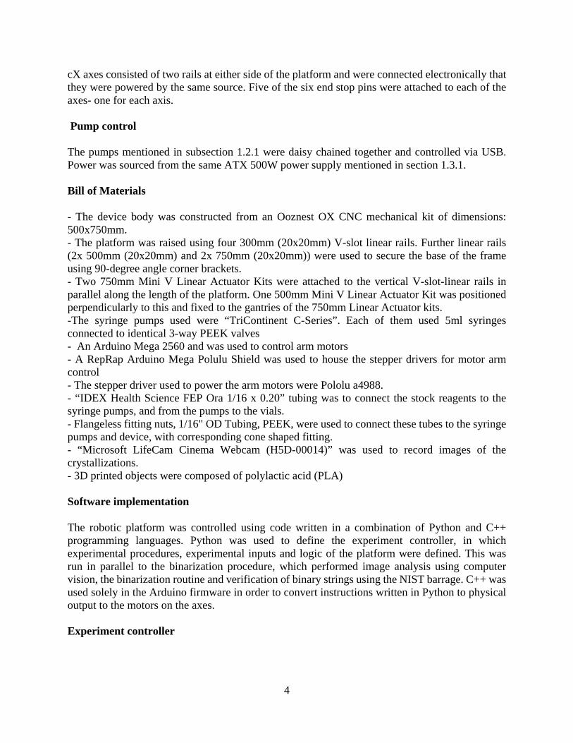
cX axes consisted of two rails at either side of the platform and were connected electronically that they were powered by the same source. Five of the six end stop pins were attached to each of the axes- one for each axis. Pump control The pumps mentioned in subsection 1.2.1 were daisy chained together and controlled via USB. Power was sourced from the same ATX 500W power supply mentioned in section 1.3.1. Bill of Materials - The device body was constructed from an Ooznest OX CNC mechanical kit of dimensions: 500x750mm. - The platform was raised using four 300mm (20x20mm) V-slot linear rails. Further linear rails (2x 500mm (20x20mm) and 2x 750mm (20x20mm)) were used to secure the base of the frame using 90-degree angle corner brackets. - Two 750mm Mini V Linear Actuator Kits were attached to the vertical V-slot-linear rails in parallel along the length of the platform. One 500mm Mini V Linear Actuator Kit was positioned perpendicularly to this and fixed to the gantries of the 750mm Linear Actuator kits. -The syringe pumps used were “TriContinent C-Series”. Each of them used 5ml syringes connected to identical 3-way PEEK valves - An Arduino Mega 2560 and was used to control arm motors - A RepRap Arduino Mega Polulu Shield was used to house the stepper drivers for motor arm control - The stepper driver used to power the arm motors were Pololu a4988. - “IDEX Health Science FEP Ora 1/16 x 0.20” tubing was to connect the stock reagents to the syringe pumps, and from the pumps to the vials. - Flangeless fitting nuts, 1/16" OD Tubing, PEEK, were used to connect these tubes to the syringe pumps and device, with corresponding cone shaped fitting. - “Microsoft LifeCam Cinema Webcam (H5D-00014)” was used to record images of the crystallizations. - 3D printed objects were composed of polylactic acid (PLA) Software implementation The robotic platform was controlled using code written in a combination of Python and C++ programming languages. Python was used to define the experiment controller, in which experimental procedures, experimental inputs and logic of the platform were defined. This was run in parallel to the binarization procedure, which performed image analysis using computer vision, the binarization routine and verification of binary strings using the NIST barrage. C++ was used solely in the Arduino firmware in order to convert instructions written in Python to physical output to the motors on the axes. Experiment controller
5
The experiment controller was used to read an input file, specifying compound name, reagent volumes, reagent addition times, image acquisition period, number of images to collect and number of reactions to perform, and perform reactions and image acquisitions to meet these criteria. It adopted an object orientated approach, where the experiment, robotic platform, reaction routine and imaging routine were individual classes. Firmware The firmware was uploaded only on the Arduino board and was responsible for the motion of the axes. It was written in C++ as this is the native language for Arduino development. The code utilised two libraries, CommandHandler and CommandManager, to link output pins to specific motors and these are located on GitHub. The motors could then be controlled through Python using another library, Commanduino, also located on GitHub. Image Analysis Crystal detection relies on the use of models generated by Mask RCNN software. Initial datasets were labelled manually to create a model for each crystal type. Once models were created, they could be run on any image to identify crystals in that image. Each crystal was saved as a separate mask file, which contained pixels where the crystal was present, and black pixels elsewhere. Vial detection was performed by locating the brightest circular contour in the image from computer vision techniques. Vial centre and radius were then determined using ‘minimum enclosing circle’ technique. These data were saved as a separate text file. Binarization Binarization was obtained by iterating through crystal masks to find crystal pixels that are within the radius of the vial circle. This was followed by a calculation of the crystal width and height at pixel, as well as the distance from vial centre to the pixel. These values are multiplied apply the modulo of 256 to this figure to get an 8-bit string at this pixel. The original image is then converted to greyscale, and the color intensity value of that pixel (which is in the range of 0-255) is taken as a second 8-bit string. Finally, an exclusive OR operation is applied between the two 8-bit strings and the output is taken as the random string for that pixel. Longer random strings were then built up by concatenating strings obtained from pixels of one crystal, crystals of one image, and images of each reaction at synchronous times in an experiment. NIST barrage The NIST barrage was incorporated into the analysis capability of the platform to allow continuous assessment of number strings being produced. Each of the 15 tests were written in Python and verified against the bit-strings provided in the package for the numbers e, pi¸√2, and √3. These numbers are also provided in the analysis software of the platform. A brief description of each test can be seen in Supplementary Table 1.
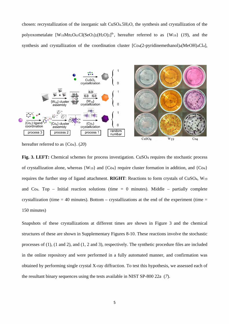
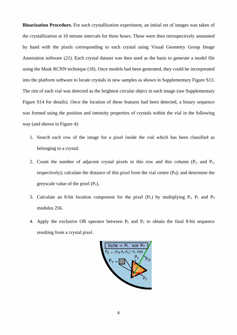
6
Supplementary Figures
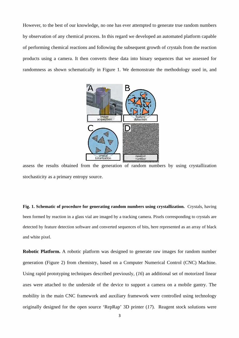
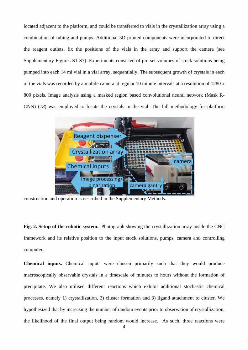
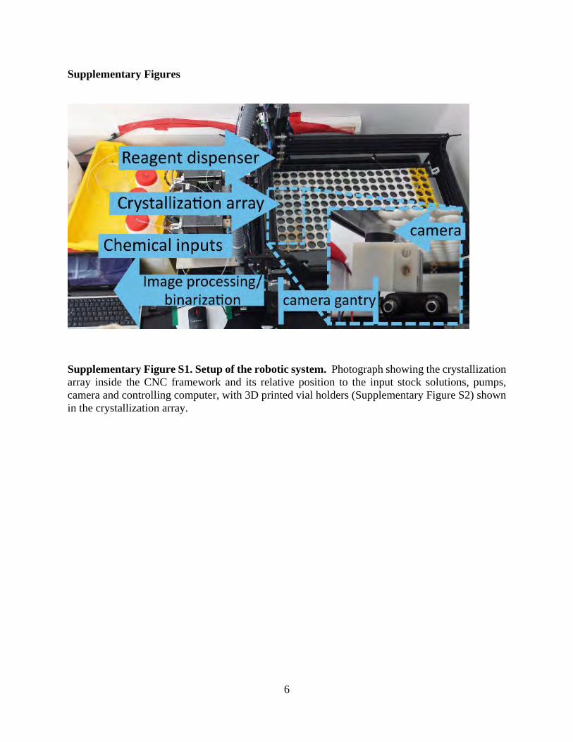
Supplementary Figure S1. Setup of the robotic system. Photograph showing the crystallization array inside the CNC framework and its relative position to the input stock solutions, pumps, camera and controlling computer, with 3D printed vial holders (Supplementary Figure S2) shown in the crystallization array.
7
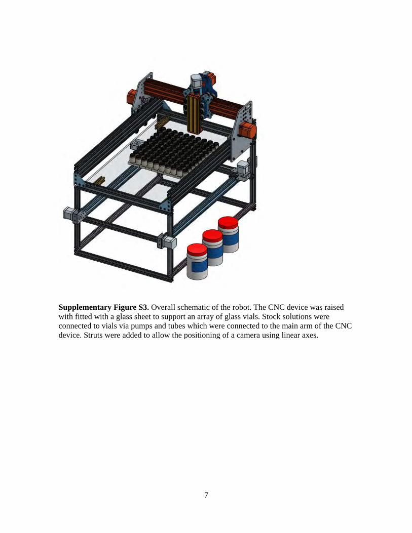
Supplementary Figure S3. Overall schematic of the robot. The CNC device was raised with fitted with a glass sheet to support an array of glass vials. Stock solutions were connected to vials via pumps and tubes which were connected to the main arm of the CNC device. Struts were added to allow the positioning of a camera using linear axes.
8
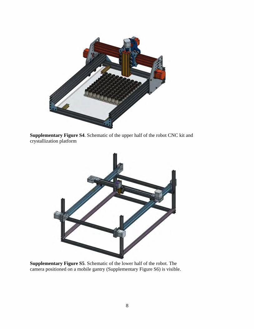
Supplementary Figure S4. Schematic of the upper half of the robot CNC kit and crystallization platform
Supplementary Figure S5. Schematic of the lower half of the robot. The camera positioned on a mobile gantry (Supplementary Figure S6) is visible.
9
Supplementary Figure S6. Mobile camera gantry. The camera is positioned in a 3d printed holder (Supplementary Figure S9) and attached to the gantry of a linear axis via an aluminium strut. Both ends of the linear axis are attached to the gantries of two further linear axes which are themselves attached to the main robot frame (not shown).
Supplementary Figure S9. 3d printed camera holder, with attachment points to an aluminium strut
Supplementary Figure S7. 3d printed vial holder. Design allows individual pieces to be clipped together permitting an array to be created.
Supplementary Figure S8. 3d printed part to direct tubing output into vial.
Supplementary Figure S13. Vial detection image processing method. Top left: original frame; Top right: colorspace conversion from bgr to hsv; Bottom left: separation of crystals from background by applying a pixel color threshold to the hsv image. Bottom right: Identification of large, central, circular contour as corresponding to the vial rim.
12
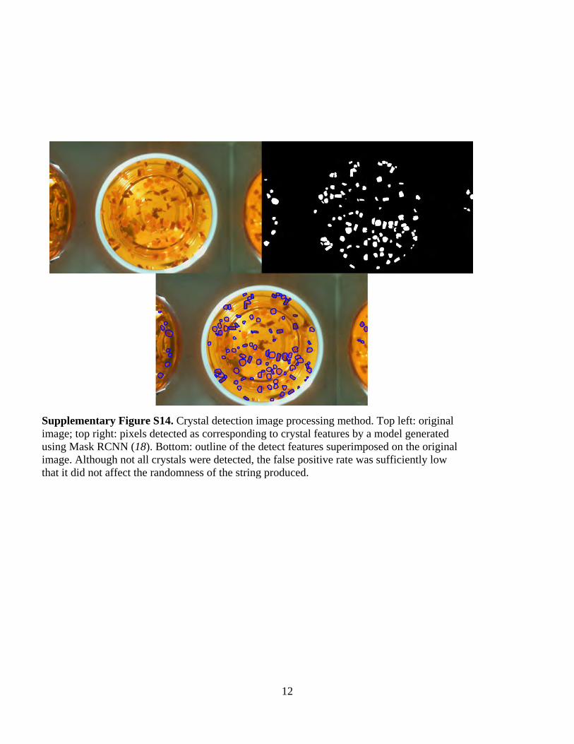
Supplementary Figure S14. Crystal detection image processing method. Top left: original image; top right: pixels detected as corresponding to crystal features by a model generated using Mask RCNN (18). Bottom: outline of the detect features superimposed on the original image. Although not all crystals were detected, the false positive rate was sufficiently low that it did not affect the randomness of the string produced.
13
Supplementary Figure S15. Data for three levels of NIST random number testing (7) for crystallization of CuSO4 after 2 hours. Left: histograms of p-values for each test; top right: uniformity p-value for each histogram. Each of these are well above the threshold of 0.0001 indicating a uniform distribution; bottom right: pass rate for each test. The dashed line indicates the expected pass rate with a significance level set at 0.01. The lower solid line indicates three standard deviations from the expected mean.
14
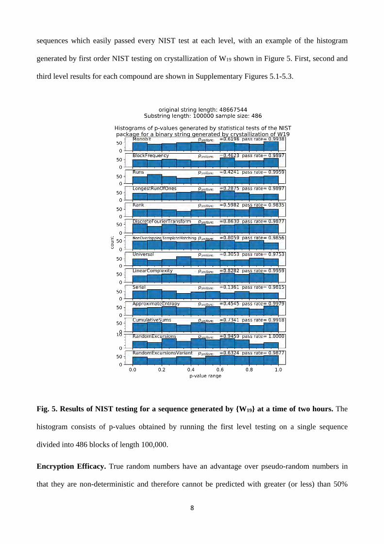
Supplementary Figure S16. Data for three levels of NIST random number testing (7) for crystallization of {W19} after 2 hours. Left: histograms of p-values for each test; top right: uniformity p-value for each histogram. Each of these are well above the threshold of 0.0001 indicating a uniform distribution; bottom right: pass rate for each test. The dashed line indicates the expected pass rate with a significance level set at 0.01. The lower solid line indicates three standard deviations from the expected mean.
15
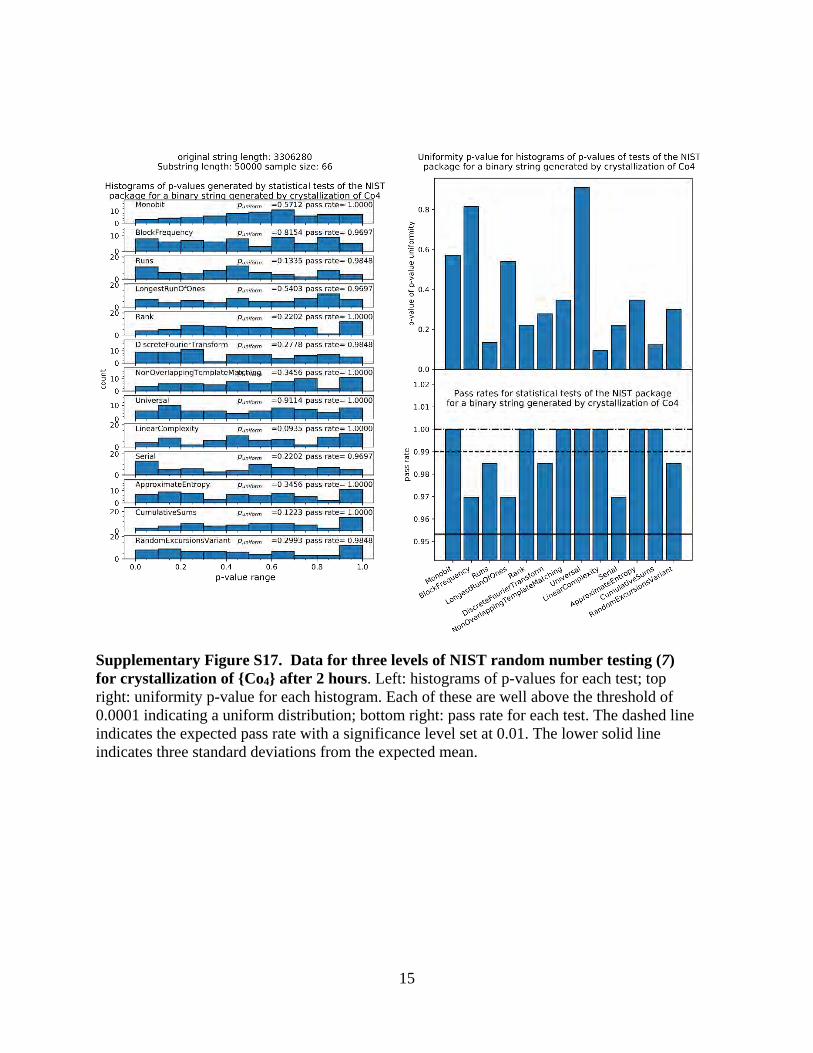
Supplementary Figure S17. Data for three levels of NIST random number testing (7) for crystallization of {Co4} after 2 hours. Left: histograms of p-values for each test; top right: uniformity p-value for each histogram. Each of these are well above the threshold of 0.0001 indicating a uniform distribution; bottom right: pass rate for each test. The dashed line indicates the expected pass rate with a significance level set at 0.01. The lower solid line indicates three standard deviations from the expected mean.
16
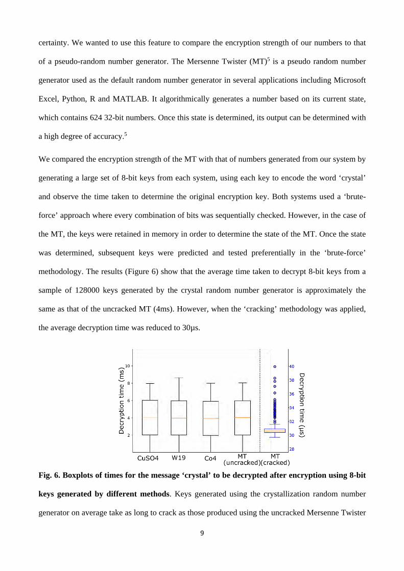
Supplementary Figure S18. Boxplots of times for the message ‘crystal’ to be decrypted after encryption using 8-bit keys generated by different methods. Keys generated using the crystallization random number generator on average take as long to crack as those produced using the uncracked Mersenne Twister (MT). However, once the state of the MT is determined, the average decryption time for this method is substantially shorter than the crystallization method. (5)
17
Supplementary tables
Test name Purpose Monobit To assess whether overall ratio of 0s and 1s is as expected for a
random bitstring. BlockFrequency To assess whether ratio of 0s and 1s in multiple substrings is as
expected for a random bitstring. Runs To assess whether number of uninterrupted sequences of identical
bits (‘runs’) is as expected for a random bitstring LongestRunOfOnes To assess whether longest uninterrupted sequence of 1s is as expected
for a random bitstring Rank To assess whether the number of long-range repetitive patterns
throughout its sequence is as expected for a random bitstring. DFT To assess whether the number of short-range repetitive patterns
throughout its sequence is as expected for a random bitstring. NonOverlapping TemplateMatching
To assess whether the number of sequences without showing repetition is as expected for a random bitstring
Universal To assess whether the compressibility of the bitstring is as expected for a random bitstring
LinearComplexity To assess whether the complexity of the bitstring is as expected for a random bitstring
Serial To assess whether the frequency of different bit patterns of different lengths is as expected for a random bitstring
Approximate Entropy
To assess whether the frequency of different overlapping bit patterns of different lengths is as expected for a random bitstring
Cusums To assess whether any maximum extent of the cumulative sum of the bitstring (treating 1 as +1 and 0 as -1) is as expected for a random bitstring
RandomExcursions To assess whether the number of a particular cusum values is as expected for a random bitstring. Note that substrings in which the cusum crosses 0 less than 500 times are rejected.
RandomExcursions Variant
To assess whether the number of deviations from a particular cusum value is as expected for a random bitstring
Supplementary Table S1. Summary of statistical tests applied to binary strings generated by the platform (7). Note that Overlapping Template Matching was omitted from the barrage due to insufficient bit-stream length in the Co4 test to obtain significant results.
18
Supplementary Equations
𝒑𝒑� ± 𝟑𝟑 �𝒑𝒑�(𝟏𝟏 − 𝒑𝒑�)
𝒎𝒎
Supplementary Equation 1. Determination of pass rate confidence interval where p̂ = 1-α, α is the significance level and m is the sample size. (7)
𝛘𝛘𝟐𝟐 = �(𝑭𝑭𝒊𝒊 − 𝒔𝒔
𝟏𝟏𝟏𝟏� )𝟐𝟐𝒔𝒔𝟏𝟏𝟏𝟏�
𝟏𝟏𝟏𝟏
𝒊𝒊=𝟏𝟏
Supplementary Equation 2. Calculation of histogram uniformity χ2 value, where Fi is the number of p-values in sub-interval I and s is the sample size. (7)
𝒑𝒑 𝒗𝒗𝒗𝒗𝒗𝒗𝒗𝒗𝒗𝒗𝑻𝑻 = 𝒊𝒊𝒊𝒊𝒗𝒗𝒎𝒎𝒊𝒊(𝟗𝟗 𝟐𝟐� , 𝛘𝛘𝟐𝟐
𝟐𝟐� )
Supplementary Equation 3. Calculation of histogram p-value where igamc is the complementary imcomplete gamma function. (7)