Glenn Research Center at Lewis Field Extended Operation of Stirling Convertors at NASA Glenn Research Center International Energy Conversion Engineering Conference August 2, 2011 Salvatore Oriti NASA Glenn Research Center RPT – Thermal Energy Conversion Branch
Transcript
Glenn Research Center at Lewis Field
Extended Operation of Stirling Convertors at NASA Glenn Research Center
International Energy Conversion Engineering Conference August 2, 2011
Salvatore Oriti NASA Glenn Research Center
RPT – Thermal Energy Conversion Branch
Glenn Research Center at Lewis Field
Introduction
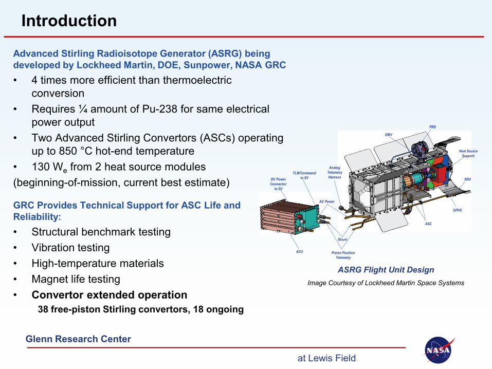
Advanced Stirling Radioisotope Generator (ASRG) being developed by Lockheed Martin, DOE, Sunpower, NASA GRC • 4 times more efficient than thermoelectric
conversion • Requires ¼ amount of Pu-238 for same electrical
power output • Two Advanced Stirling Convertors (ASCs) operating
up to 850 °C hot-end temperature • 130 We from 2 heat source modules (beginning-of-mission, current best estimate)
ASRG Flight Unit Design Image Courtesy of Lockheed Martin Space Systems
GRC Provides Technical Support for ASC Life and Reliability: • Structural benchmark testing • Vibration testing • High-temperature materials • Magnet life testing • Convertor extended operation
38 free-piston Stirling convertors, 18 ongoing
Piston Position Telemetry
Shunt
PRD
GMV
GPHS
ASC
ACU
Heat Source Support
SDU
AC Power
Analog Telemetry HarnessDC Power
Connector to SV
TLM/Command to SV
Glenn Research Center at Lewis Field
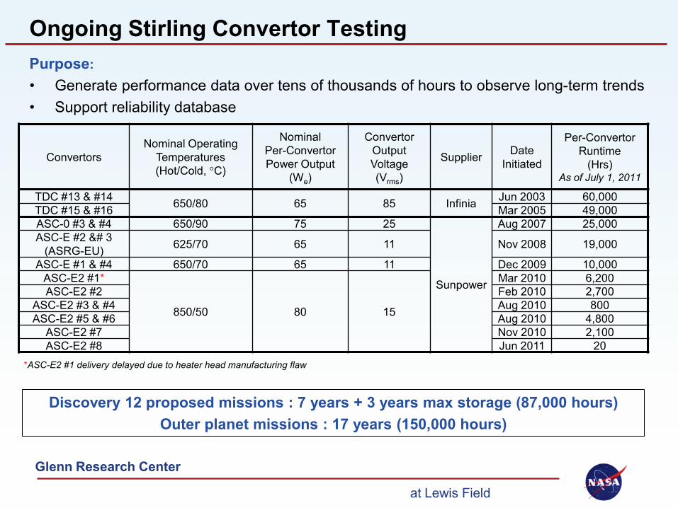
Ongoing Stirling Convertor Testing Purpose: • Generate performance data over tens of thousands of hours to observe long-term trends • Support reliability database
Discovery 12 proposed missions : 7 years + 3 years max storage (87,000 hours) Outer planet missions : 17 years (150,000 hours)
ASC-E2 #3 & #4 Aug 2010 800 ASC-E2 #5 & #6 Aug 2010 4,800
ASC-E2 #7 Nov 2010 2,100 ASC-E2 #8 Jun 2011 20
*ASC-E2 #1 delivery delayed due to heater head manufacturing flaw
Glenn Research Center at Lewis Field
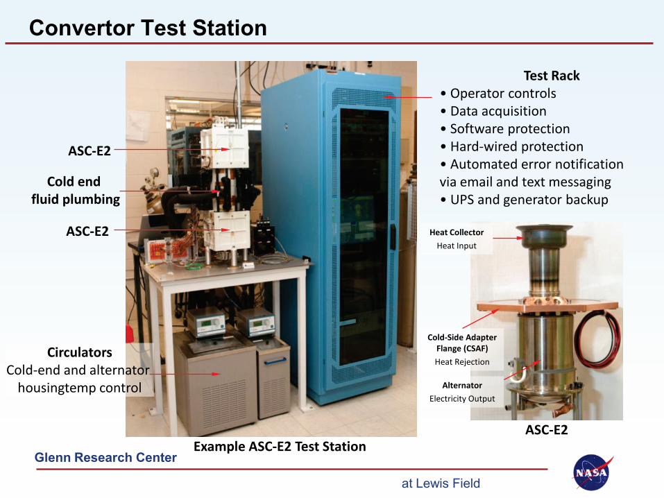
Convertor Test Station
ASC-E2
ASC-E2
Cold end fluid plumbing
Circulators Cold-end and alternator
housingtemp control
Test Rack • Operator controls • Data acquisition • Software protection • Hard-wired protection • Automated error notification via email and text messaging • UPS and generator backup
Example ASC-E2 Test Station ASC-E2
Heat Collector Heat Input
Cold-Side Adapter Flange (CSAF) Heat Rejection
Alternator Electricity Output
Glenn Research Center at Lewis Field
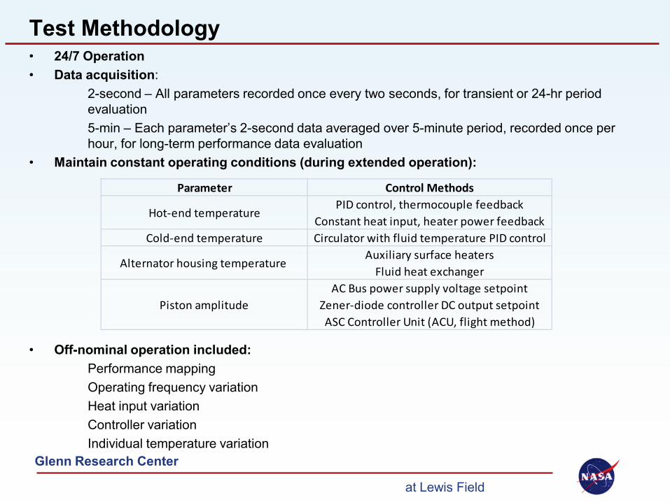
Test Methodology • 24/7 Operation • Data acquisition:
2-second – All parameters recorded once every two seconds, for transient or 24-hr period evaluation
5-min – Each parameter’s 2-second data averaged over 5-minute period, recorded once per hour, for long-term performance data evaluation
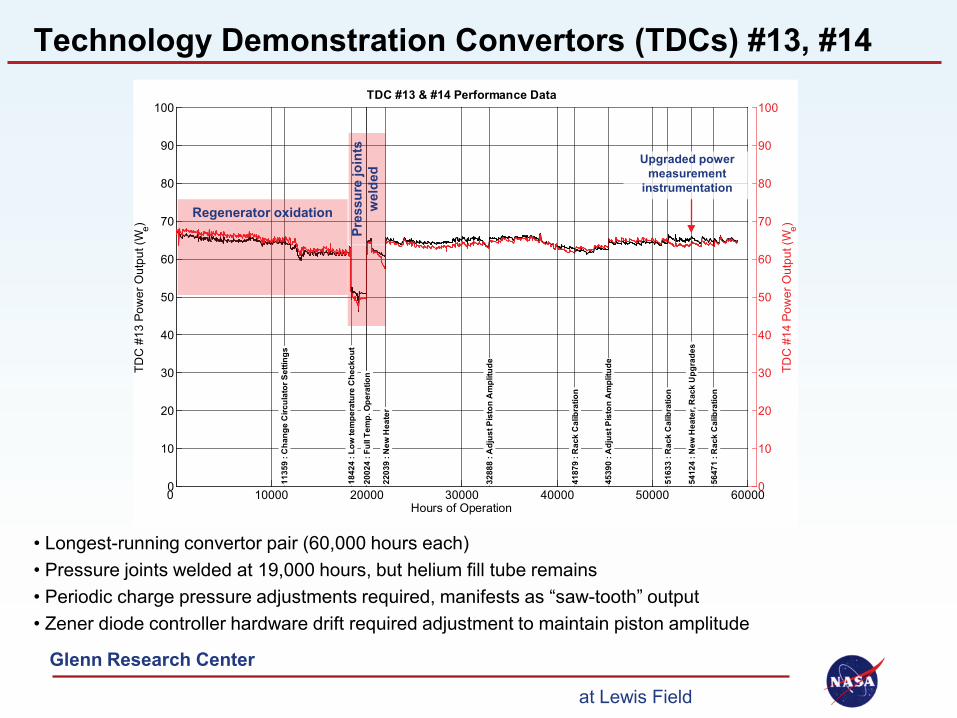
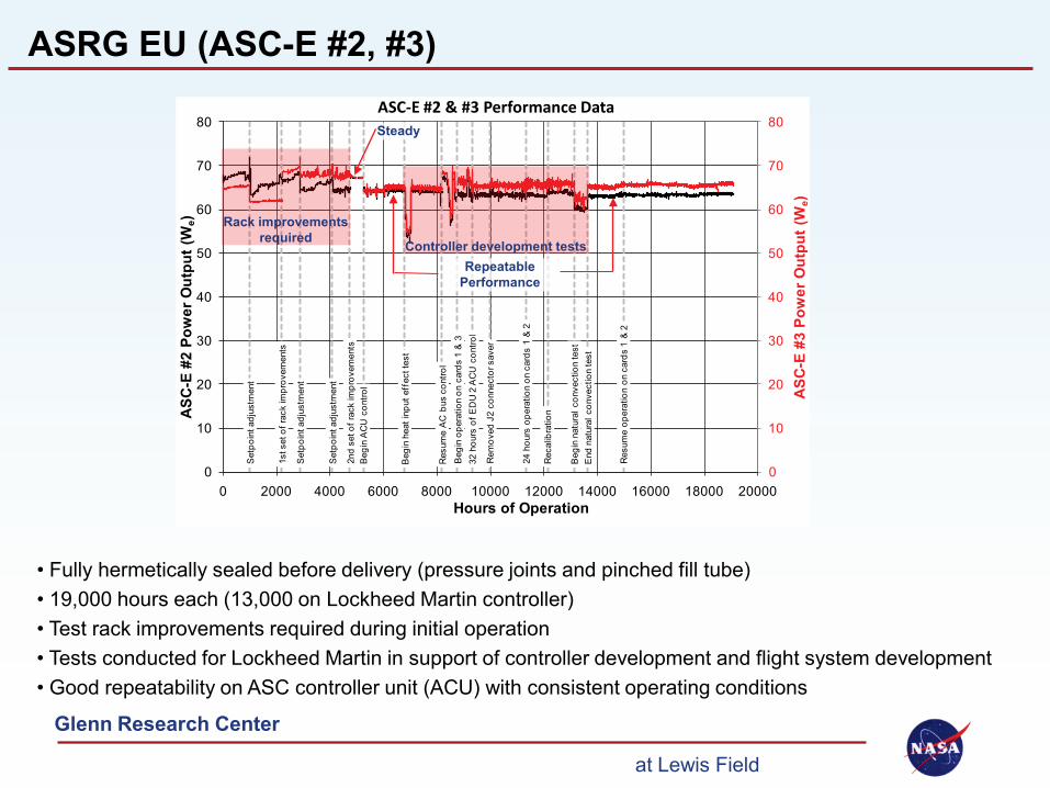
• Fully hermetically sealed before delivery (pressure joints and pinched fill tube) • 19,000 hours each (13,000 on Lockheed Martin controller) • Test rack improvements required during initial operation • Tests conducted for Lockheed Martin in support of controller development and flight system development • Good repeatability on ASC controller unit (ACU) with consistent operating conditions
Hours of OperationEff iciency = (gross heat input)/(alternator power output)
ASRG EU (ASC-E #2, #3)
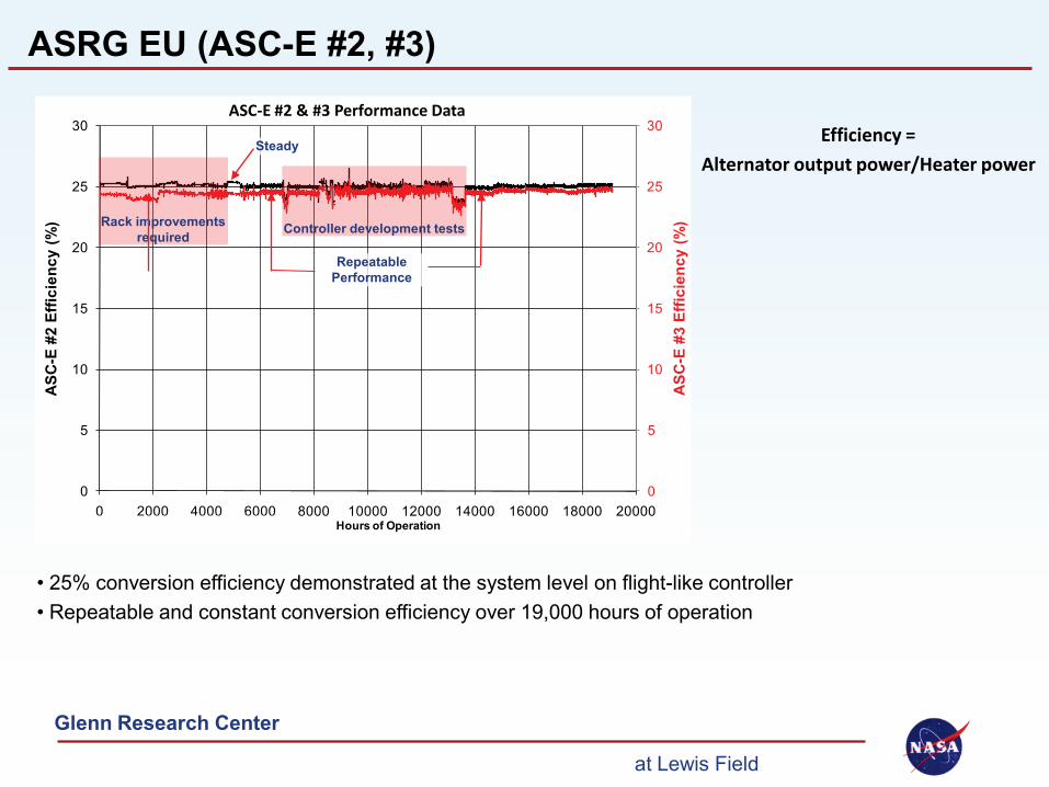
• 25% conversion efficiency demonstrated at the system level on flight-like controller • Repeatable and constant conversion efficiency over 19,000 hours of operation
Rack improvements required
Steady
Controller development tests
Repeatable Performance
Efficiency = Alternator output power/Heater power
ASC-E #2 & #3 Performance Data
Glenn Research Center at Lewis Field
0 1000 2000 3000 4000 5000 6000 0
10
20
30
40
50
60
70
80
90
100
Hours of Operation
ASC
-E2
#1 P
ower
Out
put (
We)
ASC-E2 #1 Performance Data98
: Sh
utdo
wn/
Res
tart
98 :
Initi
ated
Per
form
ance
Map
ping
296
: Ini
tiate
d Ex
tend
ed O
pera
tion
BO
M L
R
605
: Ini
t Fre
quen
cy S
wee
p
888
: Shu
tdow
n
1143
: R
esta
rt w
ith C
ompa
ct H
eat S
ourc
e13
04 :
Initi
ated
Per
form
ance
Map
ping
1476
: In
itiat
ed E
xt O
pera
tion
BO
M L
R
2629
: O
pera
ting
Poin
t Adj
ustm
ent
3223
: O
pera
ting
Poin
t Adj
ustm
ent
3849
: A
C b
us V
aria
tion
Test
4696
: Sh
utdo
wn/
Res
tart
BO
M L
R
4889
: Sh
utdo
wn/
Res
tart
BO
M L
R
5182
: Sh
utdo
wn/
Res
tart
BO
M L
R53
24 :
Tem
pora
ry A
C lo
ss
5520
: Te
mpo
rary
AC
loss
6097
: N
atur
al F
requ
ency
Tes
t61
93 :
Tran
s B
ack
to B
OM
LR
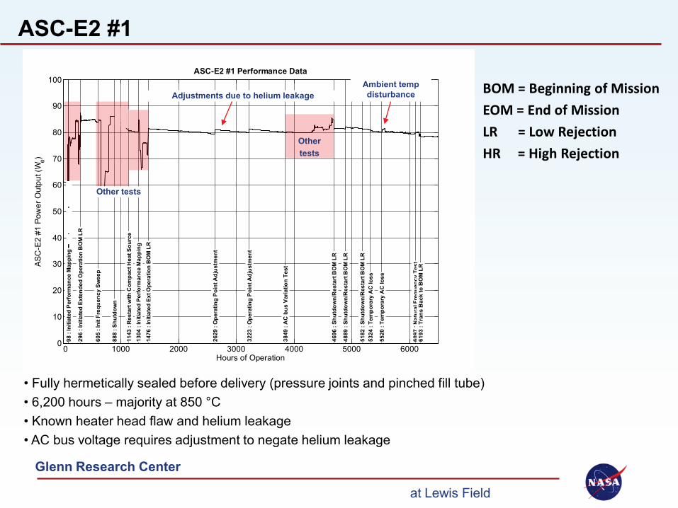
ASC-E2 #1
• Fully hermetically sealed before delivery (pressure joints and pinched fill tube) • 6,200 hours – majority at 850 °C • Known heater head flaw and helium leakage • AC bus voltage requires adjustment to negate helium leakage
Other tests
Adjustments due to helium leakage
Other tests
Ambient temp disturbance BOM = Beginning of Mission
EOM = End of Mission LR = Low Rejection HR = High Rejection
Glenn Research Center at Lewis Field
0
10
20
30
40
50
60
70
80
90
100
ASC
-E2
#6 P
ower
Out
put (
We)
0 1000 2000 3000 4000 5000 0
10
20
30
40
50
60
70
80
90
100
Hours of Operation
ASC
-E2
#5 P
ower
Out
put (
We)
ASC-E2 #5 & #6 Performance Data
855
: Che
ckou
t Com
plet
e, In
itiat
ed P
erf M
ap
1194
: In
itiat
ed E
xten
ded
Ope
ratio
n at
BO
M L
R
1914
: O
pera
ting
Poin
t Adj
ustm
ents
2202
: A
lt H
ousi
ng T
emp
Adj
ustm
ent
2323
: Sh
ut D
own/
Res
tart
EOM
LR
2480
: #5
Hea
t Sou
rce
Failu
re
2665
: Sh
utdo
wn/
Res
tart
EOM
LR
2833
: M
oved
to E
OM
HR
3019
: Se
vera
l Ope
ratin
g Po
int A
djus
tmen
ts
3192
: Sh
utdo
wn/
Res
tart
BO
M H
R
3486
: Sh
utdo
wn/
Res
tart
BO
M H
R
3823
: Te
mpo
rary
AC
loss
4233
: A
djus
ted
to B
OM
LR
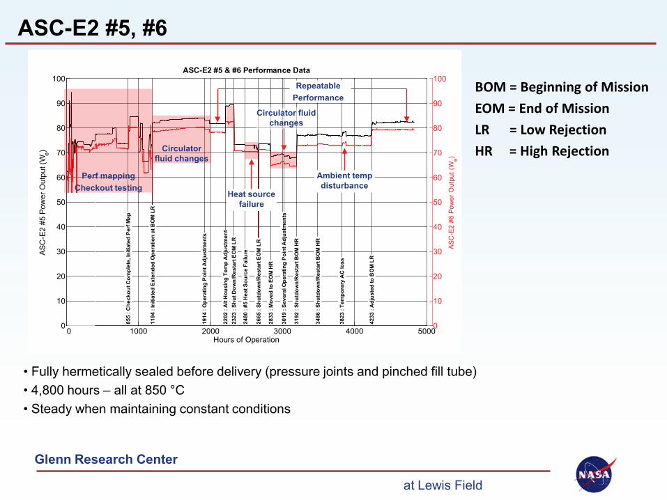
ASC-E2 #5, #6
• Fully hermetically sealed before delivery (pressure joints and pinched fill tube) • 4,800 hours – all at 850 °C • Steady when maintaining constant conditions
Perf mapping Checkout testing
Heat source failure
Circulator fluid changes
Repeatable Performance
Circulator fluid changes
Ambient temp disturbance
BOM = Beginning of Mission EOM = End of Mission LR = Low Rejection HR = High Rejection
Glenn Research Center at Lewis Field
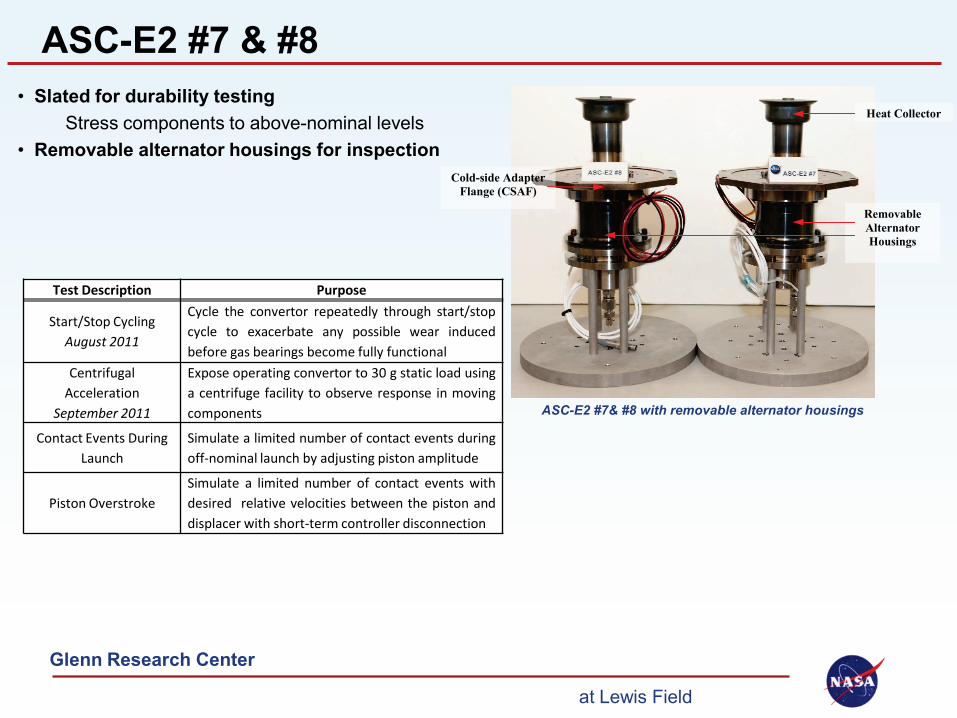
ASC-E2 #7 & #8 • Slated for durability testing
Stress components to above-nominal levels • Removable alternator housings for inspection
ASC-E2 #7& #8 with removable alternator housings
Heat Collector
Cold-side Adapter Flange (CSAF)
Removable Alternator Housings
Test Description Purpose
Start/Stop Cycling August 2011
Cycle the convertor repeatedly through start/stop cycle to exacerbate any possible wear induced before gas bearings become fully functional
Centrifugal Acceleration
September 2011
Expose operating convertor to 30 g static load using a centrifuge facility to observe response in moving components
Contact Events During Launch
Simulate a limited number of contact events during off-nominal launch by adjusting piston amplitude
Piston Overstroke Simulate a limited number of contact events with desired relative velocities between the piston and displacer with short-term controller disconnection
Glenn Research Center at Lewis Field
Conclusion GRC is supporting life and reliability database for free-piston Stirilng conversion via extended convertor operation Ongoing convertor operation: • 18 convertors (4 TDCs from Infinia, 14 ASCs from Sunpower) • 350,000 total convertor hours of operation • 218,000 on Infinia units and 132,000 on Sunpower units
Demonstrating steady convertor performance requires precise maintenance of operating conditions Sources of disruption : • Investigative tests
Varying operating frequency, hot-end temp, cold-end temp • Hot end control method
Constant heat input mode requires more user-adjustment than constant temperature mode Long-term transients in hot end insulation were observed
• Support facility Open-bath circulator fluid concentration drifting Nuisance shutdowns (instrumentation failure, EMI, power outages) Ambient temperature fluctuations due to room HVAC
Glenn Research Center at Lewis Field
Acknowledgements
This work was funded through the NASA Science Mission Directorate and the Radioisotope Power Systems Program Office. Any opinions, findings, and conclusions or recommendations expressed in this article are those of the authors and do not necessarily reflect the views of the National Aeronautics and Space Administration.