Disclosure to Promote the Right To Information Whereas the Parliament of India has set out to provide a practical regime of right to information for citizens to secure access to information under the control of public authorities, in order to promote transparency and accountability in the working of every public authority, and whereas the attached publication of the Bureau of Indian Standards is of particular interest to the public, particularly disadvantaged communities and those engaged in the pursuit of education and knowledge, the attached public safety standard is made available to promote the timely dissemination of this information in an accurate manner to the public. इंटरनेट मानक “!ान $ एक न’ भारत का +नम-ण” Satyanarayan Gangaram Pitroda “Invent a New India Using Knowledge” “प0रा1 को छोड न’ 5 तरफ” Jawaharlal Nehru “Step Out From the Old to the New” “जान1 का अ+धकार, जी1 का अ+धकार” Mazdoor Kisan Shakti Sangathan “The Right to Information, The Right to Live” “!ान एक ऐसा खजाना > जो कभी च0राया नहB जा सकता ह ै” Bhartṛhari—Nītiśatakam “Knowledge is such a treasure which cannot be stolen” IS 12275 (1987): Standard for time-to-amplitude convertors for multichannel amplitude analyzers [LITD 8: Electronic Measuring Instruments, Systems and Accessories]
Transcript
Disclosure to Promote the Right To Information
Whereas the Parliament of India has set out to provide a practical regime of right to information for citizens to secure access to information under the control of public authorities, in order to promote transparency and accountability in the working of every public authority, and whereas the attached publication of the Bureau of Indian Standards is of particular interest to the public, particularly disadvantaged communities and those engaged in the pursuit of education and knowledge, the attached public safety standard is made available to promote the timely dissemination of this information in an accurate manner to the public.
इंटरनेट मानक
“!ान $ एक न' भारत का +नम-ण”Satyanarayan Gangaram Pitroda
“Invent a New India Using Knowledge”
“प0रा1 को छोड न' 5 तरफ”Jawaharlal Nehru
“Step Out From the Old to the New”
“जान1 का अ+धकार, जी1 का अ+धकार”Mazdoor Kisan Shakti Sangathan
“The Right to Information, The Right to Live”
“!ान एक ऐसा खजाना > जो कभी च0राया नहB जा सकता है”Bhartṛhari—Nītiśatakam
“Knowledge is such a treasure which cannot be stolen”
“Invent a New India Using Knowledge”
है”ह”ह
IS 12275 (1987): Standard for time-to-amplitude convertorsfor multichannel amplitude analyzers [LITD 8: ElectronicMeasuring Instruments, Systems and Accessories]
UDC 539*1*075 : 621.374'3
IS : 12275 - 1987 IEC Pub 741 ( 1982)
Indian Standard
STANDARD FOR TIME-TO-AMPLITUDE CONVERTS
FOR MULTICHANNEL AMPLITUDE ANALYZERS
(IEC Title : Multichannel Amplitude Analyzers : Standards for Time-to-Amplitude Converters )
qational Foreword
This Indian Standard, which is identical with IEC Pub 741 ( 1982 ) ‘Multichannel amplitude .nalyzers: Standards for time-to-amplitude converters’ issued by the International Electroterhnical Commission ( IEC ), was adopted by the Bureau of Indian Standards and on the recommendation sf the Nuclear Instrumentation Sectional Committee arid approval of the Electronics and Telecom- nunication Division Council.
Wherever the words ‘International Standard’ appear, referring to this standard, they should le read as ‘Indian Standard’.
:~o&J References
In this Indian Standard, the following International Standards are referred to. Read in their espective places the corresponding Indian Standards:
International Standard Corresponding Indian Standard
EC Pub 578 ( 1977 ) Multichannel amplitude IS : 11885-1987 Specification for multi. analyzers: Types, main characteristics and technical requirements
channel amplitude analyzers ( Identical )
EC Pub 659 ( 1979. ) Test methods for multi- channel amplitude analyzers
IS : 11886-1987 Test methods for multi- ~channel amplitude analyzers ( Identical )
Only the English language text of the International Standard has been retained while adopting t in this Indian Standard.
Adopted 28 January 1987 8 November 1988, BIS I Gr 5
BU-REAU OF INDIAN STANDARDS MANAK BHAVAN, 9 BAHADUR SHAH ZAFAR MARG
NEW DELHI 110002
,
As in the Original Standard, this Page is Intentionally Left Blank
.
-1s -: 12275 - 1987 IEC Pub 741 (1982)
1. Scope
This standard applies to time-to-amplitude converters (TAC) used in conjunction with multi- channel amplitude analyzers (MCA) in the measurement of time intervals. A common application of this technique is in time-of-flight measurements, coincidence measurements, pulse shape dis- crimination technique, etc.
2. Object
The object of this standard is to present terms and definitions relating to the main characteristics of TACs. Test methods.for the major parameters are also stated.
3. General
3.1 The TACs considered in this standard are to be used in conjunction with MCAs having linear conversion characteristics as specified in IEC Publication 578: Multichannel Amplitude Ana- lyzers. Types, Main Characteristics and Technical Requirements. The characteristics measured are those of the complete system (MCA plus TAC).
The characteristics of the TAC given in this standard can only be found if the characteristics of the MCA are significantly better than those of the TAC.
3.2 I EC Pubhcation 659: Test Methods for Multichannel Amplitude Analyzers, specifies test proce- dures to be used for MCAs; reference to it should be~made where appropriate.
3.3 The general procedures of Clause 3 of I EC Publication 659 relating to the testing of MCAs are to be applied to the test procedures described herein for TACs, except that the MCA used for TAC tests shall be maintained at reference conditions whilst the conditions under which the TAC operates are varied.
3.4 This standard is not intended to imply that all the tests described herein are mandatory; but only that such tests as are carried out shall be performed in accordance with the procedures given herein.
4. Definitions
4.1 Pulses
An input signal with two determined levels for which the transition time from one level to the other is negligible in comparison to the present time on any level. The transition time is much less than the resolving time of TAC. The difference between the levels is the amplitude of the input pulse. For each of the following pulses the amplitude, polarity, timing and shape parameters shall be specified.
3 WC page 7)
H :12275 - 1987 IEC Pub 741 (1982)
4.1.1 Start pulse
A pulse whose leading edge is used to initiate a time measurement conversion sequence.
4.1.2 Stop pulse
t A pulse whose leading edge is used to end a time measurement conversion sequence.
41.3 Gate pulse
A pulse which provides a means of gating the TAC with information other than that required for the time conversion.
4.1.-4 TAC output pulse
A pulse whose amplitude is proporti’onal to the time difference between the start and stop pulses.
4.1.5 Maximum TAC output pulse amplitude
The maximum TAC output pulse amplitude obtained when the time difference between start and stop pulses equals the TAC time range set.
4.2 TAC time range
The maximum time interval acceptable between start and stop pulses. A series of time ranges is usually specified.
4.3 Conversion Jactor
The ratio of TAC output pulse amplitude to TAC time interval corresponding to the ideal linear time response. It is expressed in units of volts per unit of time.
4;4 Time response
The relationship between the start and stop pulse time difference and the TAC output pulse amplitude.
4.5 Ideal linear time response
The straight line which represents the time response over the effective range.
4.6 TAC integral non-linearity
The maximum deviation of the time response on any TAC time range from the ideal linear time response, divided by the TAC time range. It is expressed as a percentage over a defined effective range.
4.1 TAC differential non-1inearit.v
The maximum relative deviation of tjme response over a small time interval from the average value of the time response over all equal sized time intervals in any T.4C time range.
(IEC page 9) 4
IS : 12275 - 1987 IEC Pub 741 (1982)
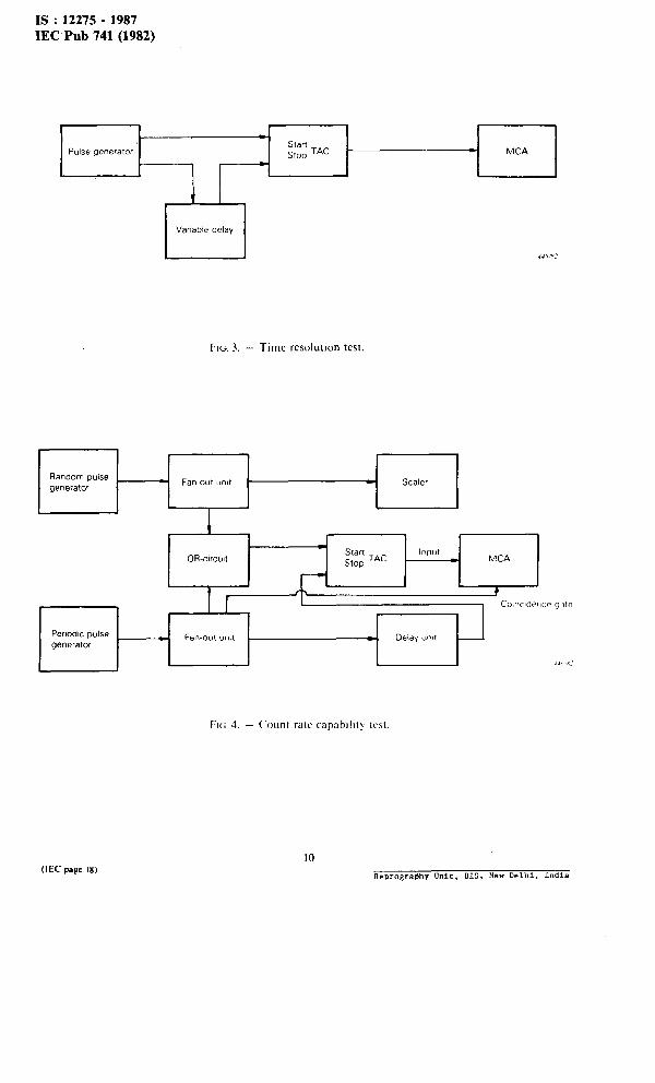
4.8 Time resolution
The full width at half maximum height of the time response peak generated from a precision time calibrator. The resolution is specified for each TAC time range, units are quoted in time units or as a percentage.
4.9 Eflective range
Limits on each TAC time range where the performance is within the stated specification.
4.10 Additional error of conversion factor with temperature change
The change of conversion factor with temperature expressed as time units per Celsius degree or as a percentage per Celsius degree for each TAC time range.
4.11 TAC reset time
The time interval after an output pulse or an over-range event required to restore the TAC to a condition in which a subsequent time conversion sequence may commence.
4.12 Minimum conversion time
The shortest time needed to process valid data completely.
4.13 Count rate capability
The input count rate at which the TAC output pulse amplitude, corresponding to a given time interval, deviates by a stated percentage from the value of the amplitude at a stated count rate.
4.14 TAC busy time
The time interval between start pulse and the end of the reset time.
5. Test methods
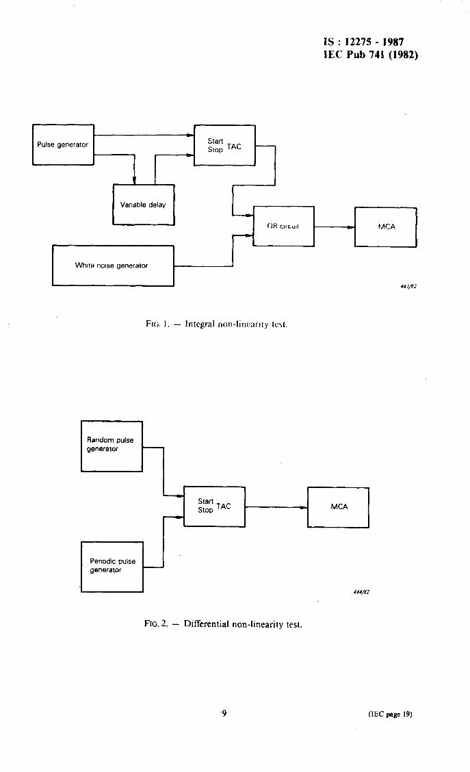
5.1 Integral non-linearity
5.1.1 Apparatus
a) a pulse generator having two coincident outputs whose pulse characteristics match the require- ments of the start and stop pulses of the TAC under test;
b) a precision variable delay unit;
c) an MCA capable of accepting the TAC output pulses;
d) a white noise generator;
e) a linear mixer;
jj a digital printer.
Items d) to f) are specified in Clause 4 of I EC Publication 659.
51.2 Preparation for the test
The apparatus is connected as shown in Figure 1, page 18. The MCA is set up to be compatible with the TAC output pulse height.
5 (IEC page I I)
IS :12275 - 1987 IEC Pub 74-l (1982)
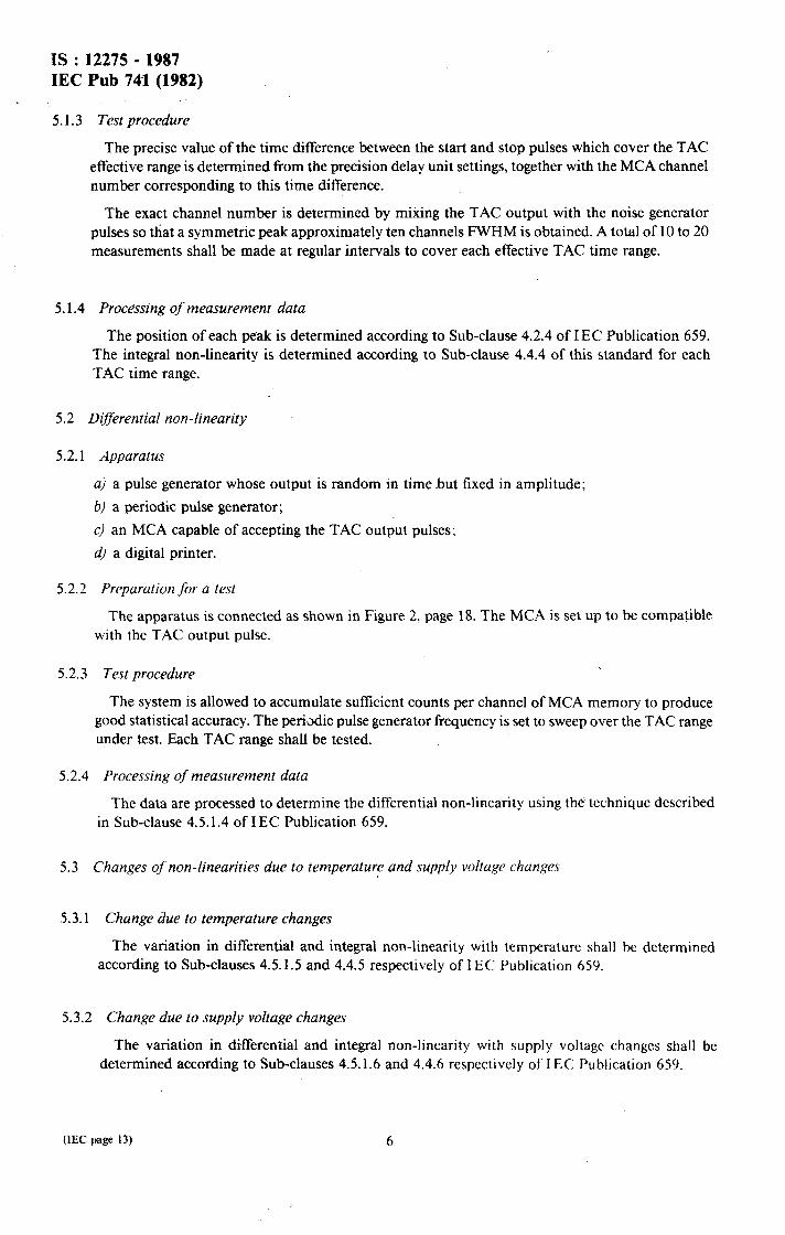
51.3 Test procedure
The precise value of the time difference between the start and stop pulses which cover the TAC ~effective range is determined from the precision delay unit settings, together with the MCA channel number corresponding to this time difference.
The exact channel number is determined by mixing the TAC output with the noise generator pulses so that a symmetric peak approximately ten channels FWHM is obtained. A total of 10 to 20 measurements shall be made at regular intervals to cover each effective TAC time range.
5.1.4 Processing of measurement data
The position of each peak is determined according to Sub-clause 4.2.4 of I EC Publication 659. The iIltegra1 non-linearity is determined according to Sub-clause 4.4.4 of this standard for each TAC time range.
5.2 Diflerential non-linearity
5.2.1 Apparatus
a) a pulse generator whose output is random in time but fixed in amplitude;
b/ a periodic pulse generator;
c) an MCA capable of accepting the TAC output pulses;
d) a digital printer.
5.2.2 Preparation for a test
The apparatus is connected as shown in Figure 2, page 18. The MCA is set up to be compatible with the TAC output pulse.
5.2.3 Test procedure
The system is allowed to accumulate sufficient counts per channel of MCA memory to produce good statistical accuracy. The periodic pulse generator frequency is set to sweep over the TAC range under test. Each TAC range shall be tested.
5.2.4 Processing of measurement data
The data are processed to determine the differential non-linearity using the technique described in Sub-clause 4.5.1.4 of I EC Publication 659.
5.3 Changes of non-linearities due to temperature and supply voltage changes
53.1 Change due to temperature changes
The variation in differential and integral non-linearity with temperature shall be determined according to Sub-clauses 4.5.1.5 and 4.4.5 respectively of I EC Publication 659.
5.3.2 Change due to supply voltage changes
The variation in differential and integral non-linearity with supply voltage changes shall be determined according to Sub-clauses 4.5.1.6 and 4.4.6 respectively of I EC Publication 659.
(1EC page 13)
IS : 12275 - 1987 IEC Pub 741 (1982) .
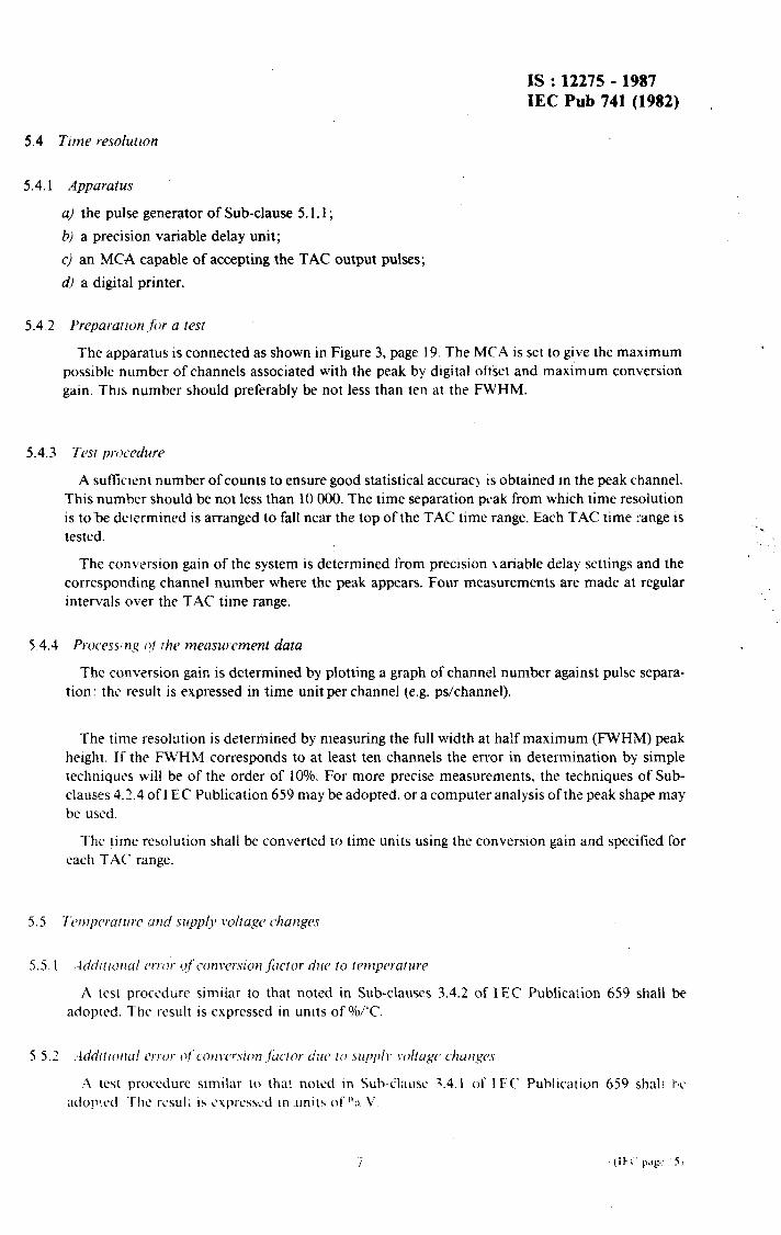
5.4 Time resolution
5.4.1 Apparaius
a) the pulse generator of Sub-clause 5.1.1;
b) a precision variable delay unit;
c) an MCA capable of accepting the TAC output pulses;
d) a digital printer.
5.4.2 Prcpararron .for a test
The apparatus is connected as shown in Figure 3, page 19. The MCA is set to give the maximum possible number of channels associated with the peak by digital of&et and maximum conversion gain. This number should preferably be not less than ten at the FWHM.
5.4.3 Tesr prf.)c.edure
A sufflclent number of counts to ensure good statistical accurac! is obtained in the peak channel. This number should be not less than 10 000. The time separation peak from which time resolution is to-be delermined is arranged to fall near the top of the TAC time range. Each TAC time range is tested.
The conversion gain of the system is determined from precision variable delay settings and the corresponding channel number where the peak appears. Four measurements are made at regular intervals over the TAC time range.
5.4.4 Processng ~1 Ihe measurement data
The conversion gain is determined by plotting a graph of channel number against pulse separa- tion: the result is expressed in time unit per channel (e.g. ps/channel).
The time resolution is determined by measuring the full width at half maximum (FWHM) peak height. If the FWHM corresponds to at least ten channels the error in determination by simple techniques will be of the order of 10%. For more precise measurements, the techniques of Sub- clauses 4.2.4 of I EC Publication 659 may be adopted, or a computer analysis of the peak shape may be used.
The time resolution shall be converted to time units using the conversion gain and specified for each TAC range.
5.5.1 .-ldditlona! error gfcon\‘t>rsion .factor due to tamyerature
A test procedure similar to that noted in Sub-clauses 3.4.2 o f I EC Publication 659 shall be adopted. The result is expressed in units of %/“C.
IS : 12275 - 1987 IEC Pub 741 (1982)
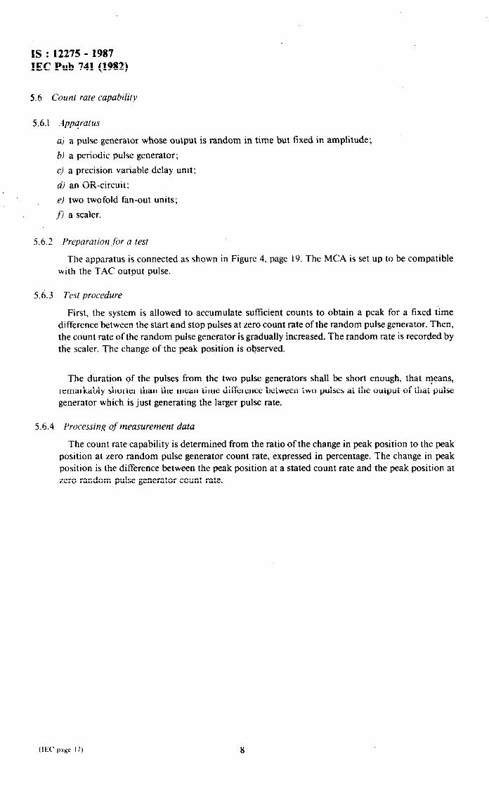
5.6 Count rate capability
5.6.1 Appqratus
a) a pulse generator whose output is random in time but fixed in amplitude;
b) a periodic pulse generator;
c) a precision variable delay unit;
d) an OR-circuit:
e) two twofold fan-out units;
f) a scaler.
5.6.2
5.63
5.6.4
Preparation .fiv a test
The apparatus is connected as shown in Figure 4, page 19. The MCA is set up to be compatible with the TAC output pulse.
Te.yt procedure
First, the system is allowed to accumulate sufficient counts to obtain a peak for a fixed time difference between the start and stop pulses at zero count rate of the random pulse generator. Then, the count rate of the random pulse generator is gradually increased. The random rate is recorded by the scaler. The change of the peak position is observed.
The duration of the pulses from the two pulse generators shall be short enough, that means, remarkably shorter than the mean time difference between two pulses at the output of that pulse generator which is just generating the larger pulse rate.
Processing of measurement data
The count rate capability is determined from the ratio of the change in peak position to the peak position at zero random pulse generator count rate, expressed in percentage. The change in peak position is the difference between the peak position at a stated count rate and the peak position at zero random pulse generator count rate.