Extensions s to Open nFlow Pro otocol in s support C Circuit Sw witching Adde endum to OpenFlow Pro otocol Specif fication (v0.8 8.9) – Circuit t Switch Add dendum v0.2 2 Augu ust 22 nd , 2009 Current M Maintainer: Saurav Das (sd 1. Intro This docu the versi Consortiu functions switches interfaces OpenFlow switch spe 2. Swit An OpenF existing c controller The circu which inp or more where ap Unlike an typically h switch (o controller extension include p interfaces oduction ment describ on v0.8.9 o um website (h of circuit sw such as pack s. According w switches fro ecification fo tch Compo Flow circuit s circuit flows r, which mana it switch flow put channels actions for e propriate it m OpenFlow p have no visib optical or ele r is responsib ns to the Ope packet interfa s. Such switch bes the requir of the Open http://OpenF itches based ket switches ly this docum om a remote r packet swit onents switch consist (or cross‐con ages the swit w table (cros are cross‐con each circuit fl maintains stat Fig acket switch, bility into pa ectronic). Acc le for provisio enFlow proto aces and ca hes should ma rements of an Flow switch FlowSwitch.or on switching with circuit ment specifie controller. T ches and not ts of a cross‐ nnects made ch over the s ss‐connect ta nnected to w low, details o tistics for the g. 1: Circuit flow ta , the cross‐co ckets (the pa cordingly no oning and rem ocol for supp n switch pa aintain separ d2@stanford. .edu ) n OpenFlow c specification rg ). This spec g time‐slots, w interfaces an s OpenFlow This documen independent circuit switch. n for packet cification cov wavelengths a nd conversel protocol cha nt should be v tly. . We recomm t switches o vers the comp and fibers. It ly circuit swi nges require viewed as an mend that you on the Open ponents and also covers h tches with p d to manage addendum t u read nFlow basic hybrid packet e such to the ‐connect tabl e in the swit ecure channe le, which cac tch), and a s el using the O ches the infor secure chann OpenFlow pro rmation abou nel to an ext otocol. ut the ternal able) contains hich output c of which will flow. able (cross‐conne onnect table i ayload). Typi packets are moving conne porting circui ckets electro ate packet an s a set of cir channels (Fig be explaine rcuit flow en . 1). Addition d in followin tries, which nally it mainta ng sections. L detail ains 1 Lastly, ect table) entry is not used to ically there is forwarded t ections in an t switching. onically, or s nd circuit flow o lookup flow s no bufferin to the contr OpenFlow cir Some moder send them o w tables as sh ws, as circuits ng within a c oller as well rcuit switch v rn circuit swi out of the c own in Fig. 2 ports circuit l. The ia the itches circuit a.
Transcript
Extensionss to OpennFlow Prootocol in ssupport CCircuit Swwitching
packet switchface. The SOName as choicbility to adaptow connectenterface on tmunications ponders are npacket switchmitters may eern ROADM/Wy, this configufaces on the ect via ROADM interfaces.
n of terms: DWDM – Time
T/SDH – Synch
OXC – Digital Cr
M/WSS – Reco
/VCG/LCAS – V
GFP – Packet ov
International T
with packet and ci
ways to interc
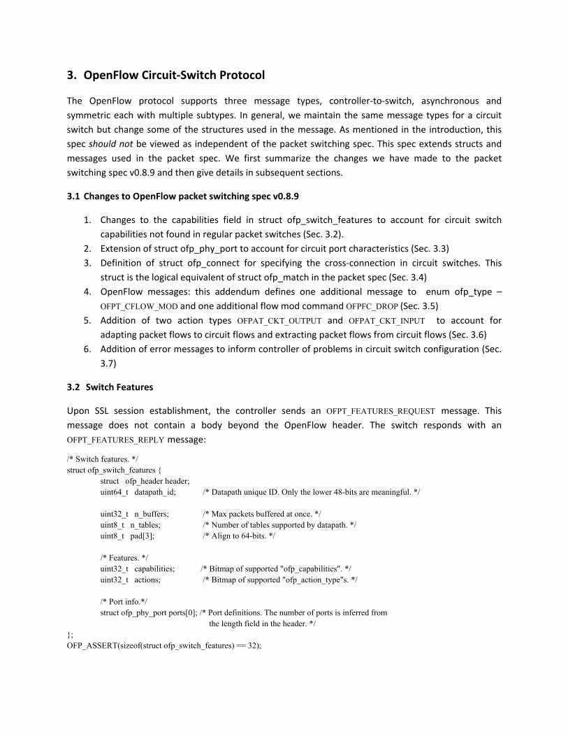
h P is conneNET switches ce I, but nowt IP packets frd via an OXCthe packet swneither doesneeded beforh now uses Deven be tunaWSS based OXuration showspacket switMs. Other int
e Division Mult
ronous Optica
ross‐connect/
onfigurable Op
Virtual Concate
ver SONET fram
Telecommunica
ircuit hardware fl
connect pack
ected to the (DXC) are con
w the P is conrom the Ethe such a fiber witch does nos it use there the signal iDWDM transcble. The statXCs. s that the actch could be terfaces can
tiplexing/ Dens
l NETwork/ Sy
Optical Cross‐c
ptical Add Drop
enation/ Virtua
ming/ Generic
ations Union
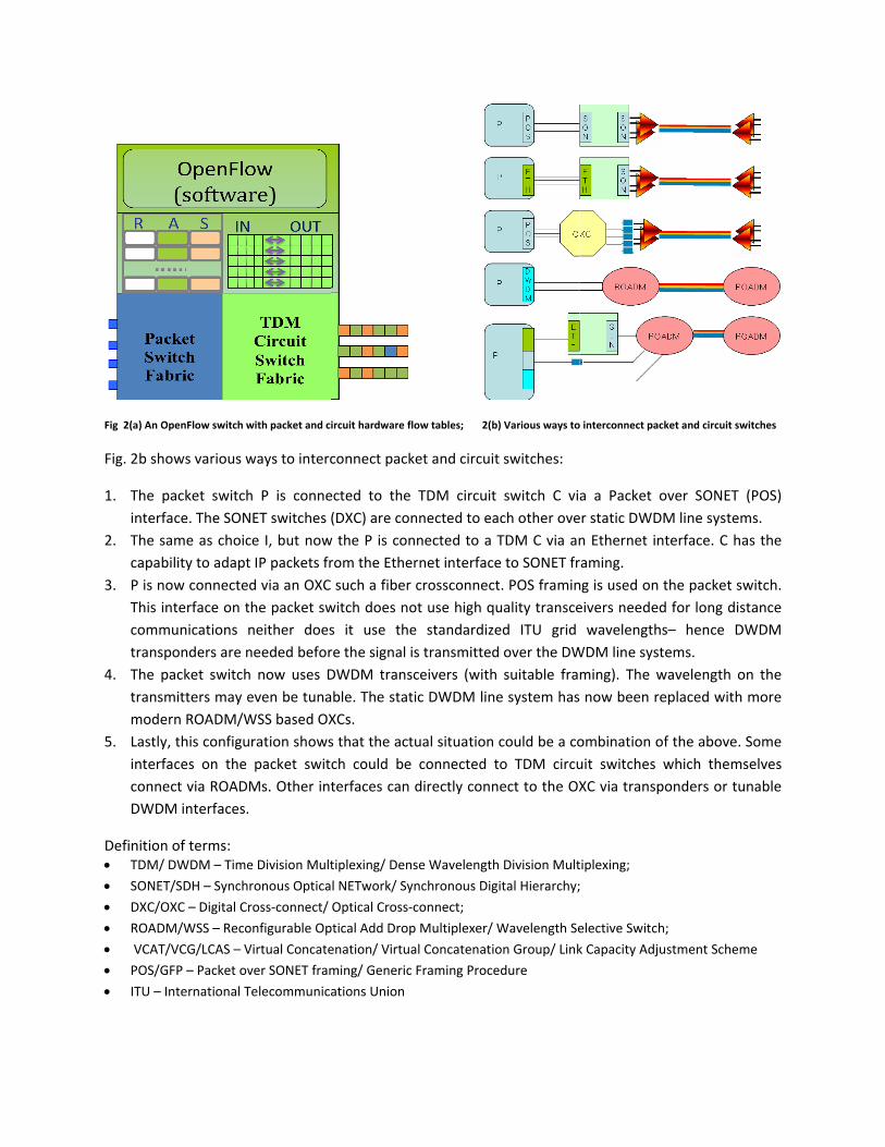
ow tables; 2(b
ket and circuit
TDM circuit nnected to eannected to a rnet interfacecrossconnectot use high que standardizes transmittedceivers (withic DWDM line
ual situation connected tdirectly conn
se Wavelength
nchronous Dig
connect;
p Multiplexer/ W
al Concatenatio
Framing Proce
b) Various ways to
t switches:
switch C viach other oveTDM C via ane to SONET frt. POS framinuality transceed ITU grid d over the DW suitable frae system has
could be a coto TDM circunect to the OX
h Division Mult
gital Hierarchy;
Wavelength Se
on Group/ Link
edure
o interconnect paccket and circuit swwitches
a a Packet oer static DWD
over SONET M line system
(POS) ms.
n Ethernet inraming.
nterface. C haas the
ng is used on eivers neededwavelength
WDM line syst
the packet swd for long diss– hence DWtems.
witch. stance WDM
ming). The w now been re
wavelength oeplaced with
n the more
ombination ouit switches XC via transp
of the above. which themsponders or tu
Some selves nable
tiplexing;
;
elective Switch
k Capacity Adju
h;
ustment Schemme
3. OpenFlow Circuit‐Switch Protocol
The OpenFlow protocol supports three message types, controller‐to‐switch, asynchronous and symmetric each with multiple subtypes. In general, we maintain the same message types for a circuit switch but change some of the structures used in the message. As mentioned in the introduction, this spec should not be viewed as independent of the packet switching spec. This spec extends structs and messages used in the packet spec. We first summarize the changes we have made to the packet switching spec v0.8.9 and then give details in subsequent sections.
3.1 Changes to OpenFlow packet switching spec v0.8.9
1. Changes to the capabilities field in struct ofp_switch_features to account for circuit switch capabilities not found in regular packet switches (Sec. 3.2).
2. Extension of struct ofp_phy_port to account for circuit port characteristics (Sec. 3.3) 3. Definition of struct ofp_connect for specifying the cross‐connection in circuit switches. This
struct is the logical equivalent of struct ofp_match in the packet spec (Sec. 3.4) 4. OpenFlow messages: this addendum defines one additional message to enum ofp_type –
OFPT_CFLOW_MOD and one additional flow mod command OFPFC_DROP (Sec. 3.5) 5. Addition of two action types OFPAT_CKT_OUTPUT and OFPAT_CKT_INPUT to account for
adapting packet flows to circuit flows and extracting packet flows from circuit flows (Sec. 3.6) 6. Addition of error messages to inform controller of problems in circuit switch configuration (Sec.
3.7)
3.2 Switch Features
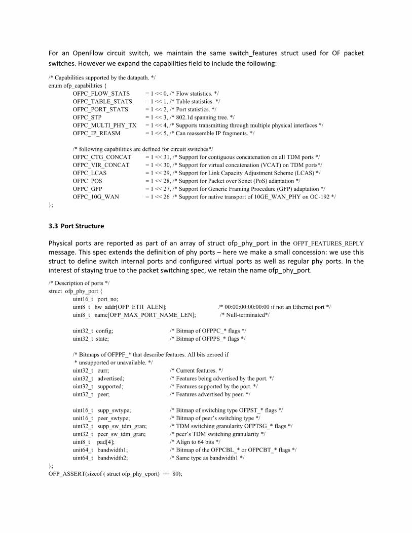
Upon SSL session establishment, the controller sends an OFPT_FEATURES_REQUEST message. This message does not contain a body beyond the OpenFlow header. The switch responds with an OFPT_FEATURES_REPLY message:
struct ofp_header header; uint64_t datapath_id; /* Datapath unique ID. Only the lower 48-bits are meaningful. */ uint32_t n_buffers; /* Max packets buffered at once. */ uint8_t n_tables; /* Number of tables supported by datapath. */ uint8_t pad[3]; /* Align to 64-bits. */ /* Features. */ uint32_t capabilities; /* Bitmap of supported "ofp_capabilities". */ uint32_t actions; /* Bitmap of supported "ofp_action_type"s. */ /* Port info.*/ struct ofp_phy_port ports[0]; /* Port definitions. The number of ports is inferred from
the length field in the header. */ }; OFP_ASSERT(sizeof(struct ofp_switch_features) == 32);
For an OpenFlow circuit switch, we maintain the same switch_features struct used for OF packet switches. However we expand the capabilities field to include the following:
/* Capabilities supported by the datapath. */ enum ofp_capabilities {
OFPC_FLOW_STATS = 1 << 0, /* Flow statistics. */ OFPC_TABLE_STATS = 1 << 1, /* Table statistics. */ OFPC_PORT_STATS = 1 << 2, /* Port statistics. */ OFPC_STP = 1 << 3, /* 802.1d spanning tree. */ OFPC_MULTI_PHY_TX = 1 << 4, /* Supports transmitting through multiple physical interfaces */ OFPC_IP_REASM = 1 << 5, /* Can reassemble IP fragments. */ /* following capabilities are defined for circuit switches*/ OFPC_CTG_CONCAT = 1 << 31, /* Support for contiguous concatenation on all TDM ports */ OFPC_VIR_CONCAT = 1 << 30, /* Support for virtual concatenation (VCAT) on TDM ports*/ OFPC_LCAS = 1 << 29, /* Support for Link Capacity Adjustment Scheme (LCAS) */ OFPC_POS = 1 << 28, /* Support for Packet over Sonet (PoS) adaptation */ OFPC_GFP = 1 << 27, /* Support for Generic Framing Procedure (GFP) adaptation */ OFPC_10G_WAN = 1 << 26 /* Support for native transport of 10GE_WAN_PHY on OC-192 */
};
3.3 Port Structure
Physical ports are reported as part of an array of struct ofp_phy_port in the OFPT_FEATURES_REPLY message. This spec extends the definition of phy ports – here we make a small concession: we use this struct to define switch internal ports and configured virtual ports as well as regular phy ports. In the interest of staying true to the packet switching spec, we retain the name ofp_phy_port.
/* Description of ports */ struct ofp_phy_port { uint16_t port_no; uint8_t hw_addr[OFP_ETH_ALEN]; /* 00:00:00:00:00:00 if not an Ethernet port */ uint8_t name[OFP_MAX_PORT_NAME_LEN]; /* Null-terminated*/ uint32_t config; /* Bitmap of OFPPC_* flags */ uint32_t state; /* Bitmap of OFPPS_* flags */
/* Bitmaps of OFPPF_* that describe features. All bits zeroed if * unsupported or unavailable. */
uint32_t curr; /* Current features. */ uint32_t advertised; /* Features being advertised by the port. */ uint32_t supported; /* Features supported by the port. */ uint32_t peer; /* Features advertised by peer. */
uint16_t supp_swtype; /* Bitmap of switching type OFPST_* flags */ unit16_t peer_swtype; /* Bitmap of peer’s switching type */ uint32_t supp_sw_tdm_gran; /* TDM switching granularity OFPTSG_* flags */ uint32_t peer_sw_tdm_gran; /* peer’s TDM switching granularity */ uint8_t pad[4]; /* Align to 64 bits */ unit64_t bandwidth1; /* Bitmap of the OFPCBL_* or OFPCBT_* flags */ uint64_t bandwidth2; /* Same type as bandwidth1 */ }; OFP_ASSERT(sizeof ( struct ofp_phy_cport) == 80);
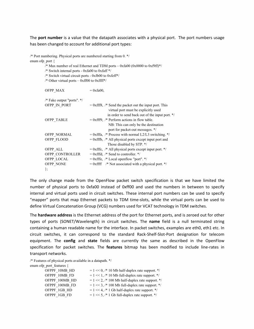
The port number is a value that the datapath associates with a physical port. The port numbers usage has been changed to account for additional port types:
/* Port numbering. Physical ports are numbered starting from 0. */ enum ofp_port {
/* Max number of real Ethernet and TDM ports – 0xfa00 (0x0000 to 0xf9ff)*/ /* Switch internal ports - 0xfa00 to 0xfaff */ /* Switch virtual circuit ports - 0xfb00 to 0xfeff*/ /* Other virtual ports – 0xff00 to 0xffff*/ OFPP_MAX = 0xfa00, /* Fake output "ports". */ OFPP_IN_PORT = 0xfff8, /* Send the packet out the input port. This virtual port must be explicitly used in order to send back out of the input port. */ OFPP_TABLE = 0xfff9, /* Perform actions in flow table. NB: This can only be the destination port for packet-out messages. */ OFPP_NORMAL = 0xfffa, /* Process with normal L2/L3 switching. */ OFPP_FLOOD = 0xfffb, /* All physical ports except input port and Those disabled by STP. */ OFPP_ALL = 0xfffc, /* All physical ports except input port. */ OFPP_CONTROLLER = 0xfffd, /* Send to controller. */ OFPP_LOCAL = 0xfffe, /* Local openflow "port". */ OFPP_NONE = 0xffff /* Not associated with a physical port. */ };
The only change made from the OpenFlow packet switch specification is that we have limited the number of physical ports to 0xfa00 instead of 0xff00 and used the numbers in between to specify internal and virtual ports used in circuit switches. These internal port numbers can be used to specify “mapper” ports that map Ethernet packets to TDM time‐slots, while the virtual ports can be used to define Virtual Concatenation Group (VCG) numbers used for VCAT technology in TDM switches.
The hardware address is the Ethernet address of the port for Ethernet ports, and is zeroed out for other types of ports (SONET/Wavelength) in circuit switches. The name field is a null terminated string containing a human readable name for the interface. In packet switches, examples are eth0, eth1 etc. In circuit switches, it can correspond to the standard Rack‐Shelf‐Slot‐Port designation for telecom equipment. The config and state fields are currently the same as described in the OpenFlow specification for packet switches. The features bitmap has been modified to include line‐rates in transport networks.
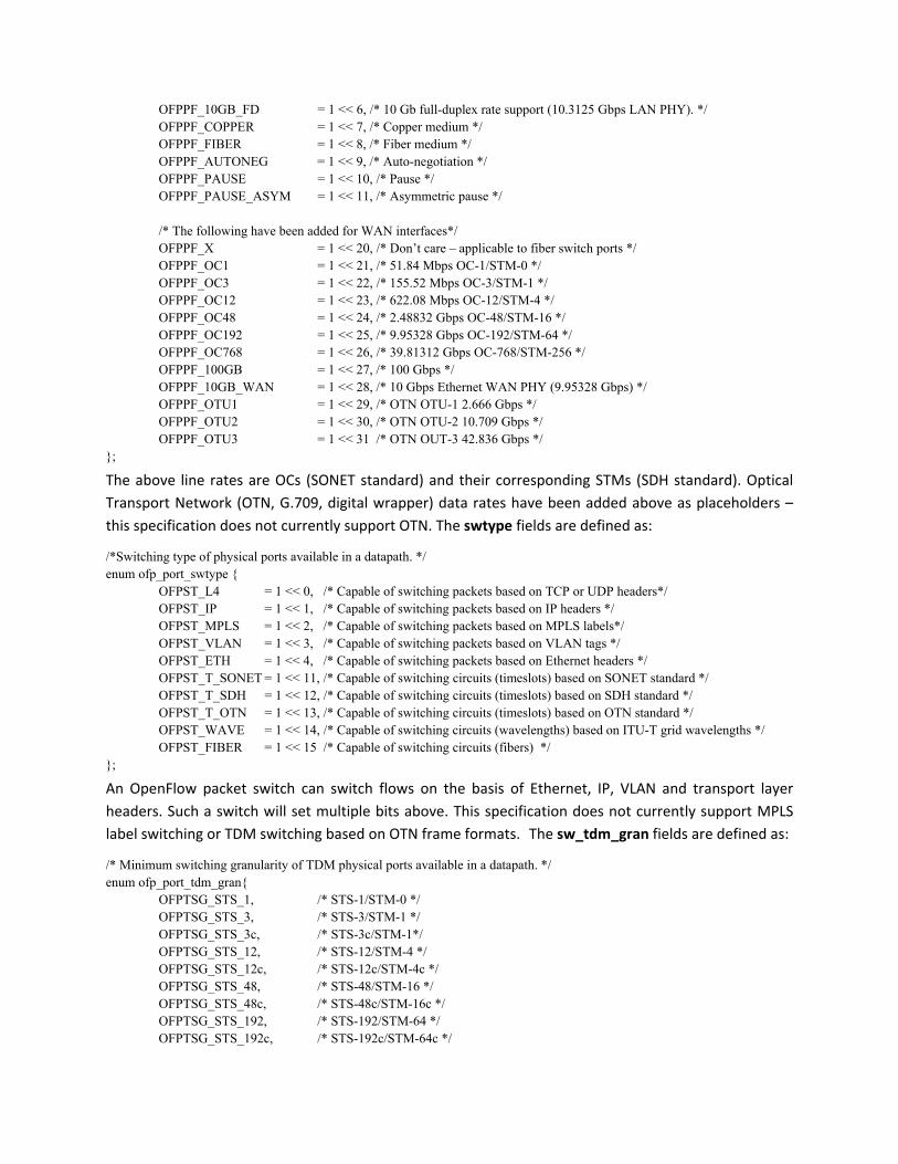
/* Features of physical ports available in a datapath. */ enum ofp_port_features {
The above line rates are OCs (SONET standard) and their corresponding STMs (SDH standard). Optical Transport Network (OTN, G.709, digital wrapper) data rates have been added above as placeholders – this specification does not currently support OTN. The swtype fields are defined as:
/*Switching type of physical ports available in a datapath. */ enum ofp_port_swtype {
OFPST_L4 = 1 << 0, /* Capable of switching packets based on TCP or UDP headers*/ OFPST_IP = 1 << 1, /* Capable of switching packets based on IP headers */ OFPST_MPLS = 1 << 2, /* Capable of switching packets based on MPLS labels*/ OFPST_VLAN = 1 << 3, /* Capable of switching packets based on VLAN tags */ OFPST_ETH = 1 << 4, /* Capable of switching packets based on Ethernet headers */ OFPST_T_SONET = 1 << 11, /* Capable of switching circuits (timeslots) based on SONET standard */ OFPST_T_SDH = 1 << 12, /* Capable of switching circuits (timeslots) based on SDH standard */ OFPST_T_OTN = 1 << 13, /* Capable of switching circuits (timeslots) based on OTN standard */ OFPST_WAVE = 1 << 14, /* Capable of switching circuits (wavelengths) based on ITU-T grid wavelengths */ OFPST_FIBER = 1 << 15 /* Capable of switching circuits (fibers) */
};
An OpenFlow packet switch can switch flows on the basis of Ethernet, IP, VLAN and transport layer headers. Such a switch will set multiple bits above. This specification does not currently support MPLS label switching or TDM switching based on OTN frame formats. The sw_tdm_gran fields are defined as:
/* Minimum switching granularity of TDM physical ports available in a datapath. */ enum ofp_port_tdm_gran{
The STS‐*c signal bits should only be set if the switch supports contiguous concatenation in the switch capabilities. Note that the OpenFlow protocol does not support TDM signals smaller than STS‐1 –i.e. no SONET VT’s or SDH LOVC’s are supported.
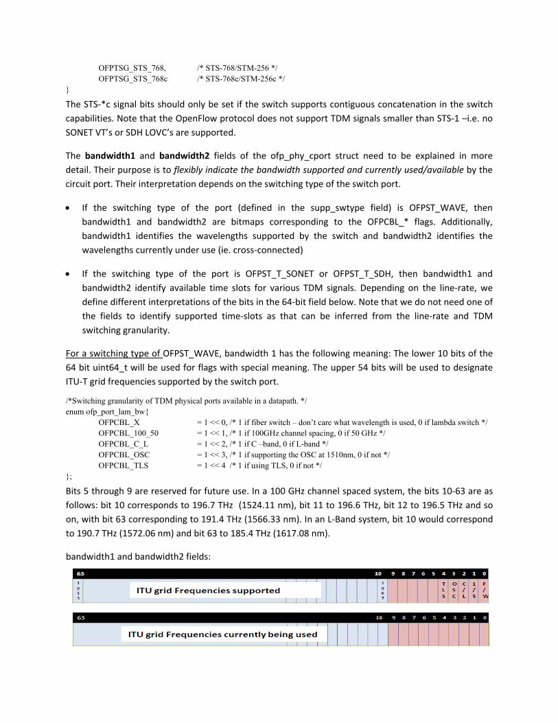
The bandwidth1 and bandwidth2 fields of the ofp_phy_cport struct need to be explained in more detail. Their purpose is to flexibly indicate the bandwidth supported and currently used/available by the circuit port. Their interpretation depends on the switching type of the switch port.
• If the switching type of the port (defined in the supp_swtype field) is OFPST_WAVE, then bandwidth1 and bandwidth2 are bitmaps corresponding to the OFPCBL_* flags. Additionally, bandwidth1 identifies the wavelengths supported by the switch and bandwidth2 identifies the wavelengths currently under use (ie. cross‐connected)
• If the switching type of the port is OFPST_T_SONET or OFPST_T_SDH, then bandwidth1 and bandwidth2 identify available time slots for various TDM signals. Depending on the line‐rate, we define different interpretations of the bits in the 64‐bit field below. Note that we do not need one of the fields to identify supported time‐slots as that can be inferred from the line‐rate and TDM switching granularity.
For a switching type of OFPST_WAVE, bandwidth 1 has the following meaning: The lower 10 bits of the 64 bit uint64_t will be used for flags with special meaning. The upper 54 bits will be used to designate ITU‐T grid frequencies supported by the switch port.
/*Switching granularity of TDM physical ports available in a datapath. */ enum ofp_port_lam_bw{
OFPCBL_X = 1 << 0, /* 1 if fiber switch – don’t care what wavelength is used, 0 if lambda switch */ OFPCBL_100_50 = 1 << 1, /* 1 if 100GHz channel spacing, 0 if 50 GHz */ OFPCBL_C_L = 1 << 2, /* 1 if C –band, 0 if L-band */ OFPCBL_OSC = 1 << 3, /* 1 if supporting the OSC at 1510nm, 0 if not */ OFPCBL_TLS = 1 << 4 /* 1 if using TLS, 0 if not */
};
Bits 5 through 9 are reserved for future use. In a 100 GHz channel spaced system, the bits 10‐63 are as follows: bit 10 corresponds to 196.7 THz (1524.11 nm), bit 11 to 196.6 THz, bit 12 to 196.5 THz and so on, with bit 63 corresponding to 191.4 THz (1566.33 nm). In an L‐Band system, bit 10 would correspond to 190.7 THz (1572.06 nm) and bit 63 to 185.4 THz (1617.08 nm).
bandwidth1 and bandwidth2 fields:
Although not suppomux/dembit indicaidentify awavelengincoming transpondone of bit
bit 1 is used ort a 50GHz
mux filters thates whether a fiber switchths individuafiber and thder on the pots 10‐63 shou
to identify aspaced systet are designethe flags in
h as opposedally. A fiber hus a ‘don’t ort, then the ld be set, and
100GHz system. Bit 2 ideed to operatebit 10‐63 co to a waveleswitch is typcare’ appliesswitch port sd the line‐rate
tem or a 50Gentifies a C oe in either theorrespond to ength switch pically agnos in this caseshould be tree flag OFPPF_
GHz system, tr L band syse C or L bandsC or L bandwhich can dtic to whatee. However ifated as a wa_* should be s
his specificattem. A waves but not bot wavelengthsistinguish beever signals af a fiber switvelength switset).
ion currentlyelength switch. Accordingls. Bit 0 is usetween and sare carried itch is used wtch port (bit
y does h has ly this ed to switch n the with a 0 = 0,
Another rwaveleng(though uWhile it mwithout tmux/demchannel snoise) it chighest lin
Bit 3 is usthe electprocess klaser sourTLS and tITU grid wvice versa
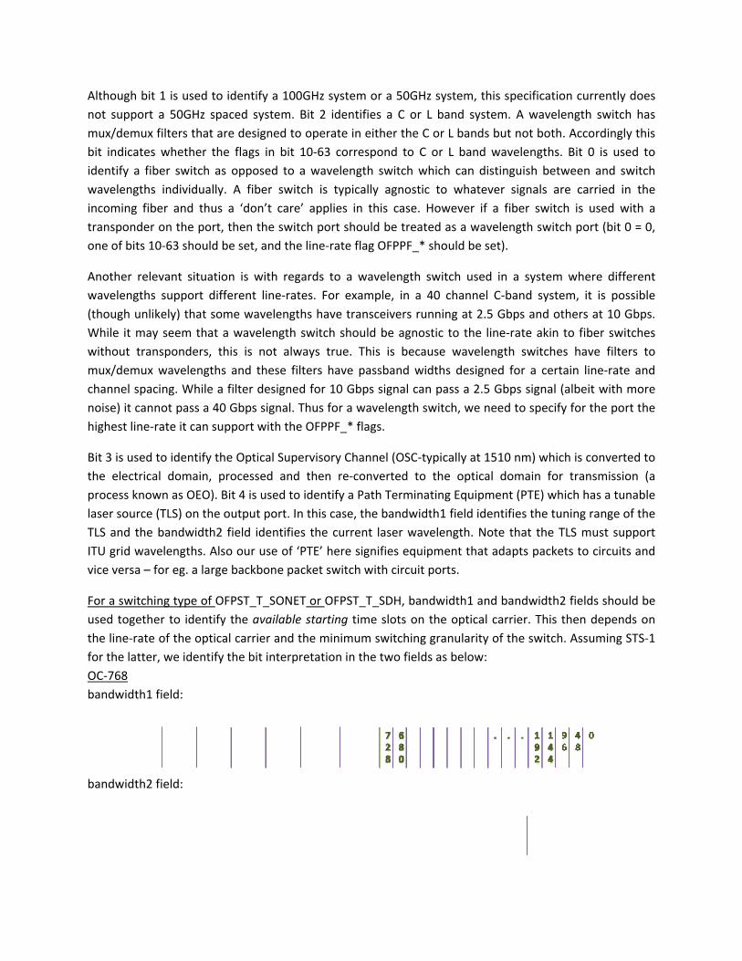
For a switused togethe line‐rafor the latOC‐768 bandwidt
bandwidt
relevant situaths support unlikely) that may seem thatranspondersmux wavelengpacing. Whilecannot pass ane‐rate it can
ed to identifyrical domainnown as OEOrce (TLS) on ththe bandwidtwavelengths. a – for eg. a la
tching type ofether to idenate of the optter, we ident
h1 field:
h2 field:
ation is withdifferent linesome waveleat a wavelen, this is not gths and these a filter desia 40 Gbps sign support with
y the Optical , processed
O). Bit 4 is usehe output poth2 field idenAlso our usearge backbon
f OFPST_T_SOtify the availtical carrier atify the bit int
regards to ae‐rates. For eengths have tgth switch shalways true
se filters havigned for 10 nal. Thus for ah the OFPPF_
Supervisory Cand then re
ed to identify rt. In this casntifies the cur of ‘PTE’ heree packet swit
ONET or OFPSlable startingand the minimterpretation i
a wavelengthexample, in atransceivers hould be agne. This is bece passband wGbps signal ca wavelength* flags.
h switch usea 40 channerunning at 2.nostic to the cause wavelewidths designcan pass a 2.5h switch, we n
d in a systeml C‐band syst5 Gbps and oline‐rate akinength switchned for a cer5 Gbps signalneed to speci
m where difftem, it is poothers at 10 n to fiber swies have filtertain line‐ratel (albeit with ify for the po
ferent ssible Gbps. itches ers to e and more rt the
Channel (OSCe‐converted ta Path Termie, the bandwrrent laser we signifies eqtch with circu
ST_T_SDH, bag time slots omum switchinin the two fie
C‐typically at 1to the opticanating Equipm
width1 field idwavelength. Nuipment thatit ports.
1510 nm) whal domain foment (PTE) wentifies the tote that the t adapts pack
ich is convertor transmissiwhich has a tuuning range oTLS must su
kets to circuit
ted to on (a nable of the pport ts and
andwidth1 anon the opticalng granularityelds as below:
nd bandwidthl carrier. Thisy of the switc:
h2 fields shous then depench. Assuming
uld be ds on STS‐1
For an OCan STS‐191. Of thesignals. Th192c and it if it is aSTS‐12 sigWhen wetime‐slot bits. Thusstarting trepresentand bits 2
C‐768 line‐rat92c signal, 16 ese, the bandhe availabilitySTS‐48c the already being gnal (out of e say 64 poss12, and choics if bits 31‐26time slot – it 4 possible s24‐63 represe
te, there is 1 possible slotsdwidth1 fieldy of time‐slotavailability ofused. Bits 20a total 64).Tsible starting ce 2 is time‐s6 of the bande. time‐slot tarting time‐ent 4 possible
possible stars for an STS‐4d identifies ats for the STS‐f the time‐slo0‐55 indicate he interpretatime‐slot choslot 24 and sowidth1 field 588. Similarlslot choices ( choices (10 b
rting timeslot48c signal, 64 ll possible ch‐768c signal iot is indicated6 possible chation of thesoices, we meo on. The 64 care for examly, bits 56‐63(8 bits each) bits each) for
t for an STS‐7for STS‐12c, hoices for STs shown by sd by setting thhoices of avase bits meritsean that choichoices can bple 110001, 3 of bandwidfor an STS‐3can STS‐1 sign
768c signal, 4256 for STS‐3TS‐768c, STS‐setting all fouhe corresponilable startings a more detice 0 is time‐be representeit represents dth1 and 0‐2c signal (out onal.
4 possible slo3c and 768 fo‐192c and STr bits 0‐3. Foding bit or zeg time‐slots ftailed explana‐slot 0, choiced in binary wthe 49th cho23 of bandwof a possible
ots for r STS‐TS‐48c r STS‐eroing for an ation. e 1 is with 6 ice of
width2 256),
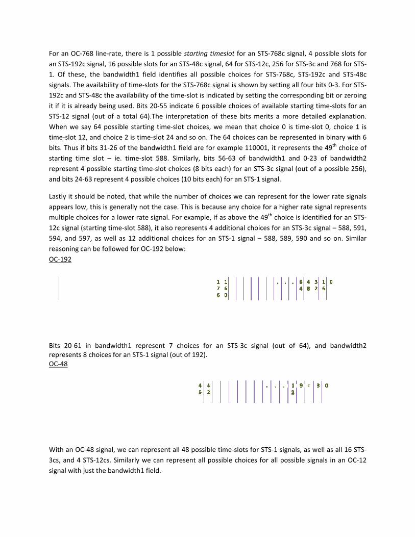
Lastly it sappears lomultiple c12c signa594, and reasoningOC‐192
Bits 20‐6representOC‐48
With an O3cs, and 4signal wit
hould be notow, this is gechoices for a l (starting tim597, as well g can be follow
1 in bandwits 8 choices fo
OC‐48 signal, 4 STS‐12cs. Sh just the ban
ted, that whilnerally not thlower rate si
me‐slot 588), ias 12 additiwed for OC‐1
idth1 represeor an STS‐1 si
we can repreSimilarly we cndwidth1 fiel
le the numbehe case. This gnal. For exait also represonal choices192 below:
ent 7 choicegnal (out of 1
esent all 48 pcan representd.
er of choices is because anmple, if as abents 4 additio for an STS‐1
es for an ST192).
possible time‐t all possible
we can repreny choice for bove the 49th
onal choices 1 signal – 58
esent for the a higher rate
h choice is idefor an STS‐3c8, 589, 590 a
lower rate se signal repreentified for anc signal – 588and so on. S
ignals esents n STS‐, 591, imilar
TS‐3c signal
‐slots for STS‐choices for a
(out of 64),
‐1 signals, as all possible s
and bandw
width2
well as all 16ignals in an O
6 STS‐OC‐12
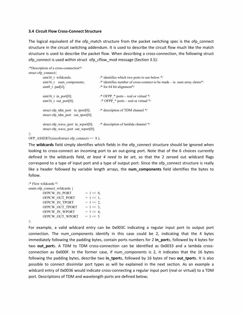
3.4 Circuit Flow Cross‐Connect Structure
The logical equivalent of the ofp_match structure from the packet switching spec is the ofp_connect structure in the circuit switching addendum. It is used to describe the circuit flow much like the match structure is used to describe the packet flow. When describing a cross‐connection, the following struct ofp_connect is used within struct ofp_cflow_mod message (Section 3.5):
/*Description of a cross-connection*/ struct ofp_connect{ uint16_t wildcards; /* identifies which two ports to use below */ uint16_t num_components; /* identifies number of cross-connect to be made – ie. num array elems*/ uint8_t pad[4]; /* for 64 bit alignment*/ uint16_t in_port[0]; /* OFPP_* ports – real or virtual */ uint16_t out_port[0]; /* OFPP_* ports – real or virtual */
The wildcards field simply identifies which fields in the ofp_connect structure should be ignored when looking to cross‐connect an incoming port to an out‐going port. Note that of the 6 choices currently defined in the wildcards field, at least 4 need to be set, so that the 2 zeroed out wildcard flags correspond to a type of input port and a type of output port. Since the ofp_connect structure is really like a header followed by variable length arrays, the num_components field identifies the bytes to follow.
For example, a valid wildcard entry can be 0x003C indicating a regular input port to output port connection. The num_components identify in this case could be 2, indicating that the 4 bytes immediately following the padding bytes, contain ports numbers for 2 in_ports, followed by 4 bytes for two out_ports. A TDM to TDM cross‐connection can be identified as 0x0033 and a lambda cross‐connection as 0x000F. In the former case, if num_components is 2, it indicates that the 16 bytes following the padding bytes, describe two in_tports, followed by 16 bytes of two out_tports. It is also possible to connect dissimilar port types as will be explained in the next section. As an example a wildcard entry of 0x0036 would indicate cross‐connecting a regular input port (real or virtual) to a TDM port. Descriptions of TDM and wavelength ports are defined below;
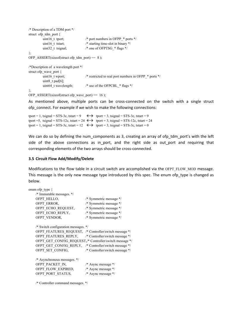
/* Description of a TDM port */ struct ofp_tdm_port { uint16_t tport; /* port numbers in OFPP_* ports */ uint16_t tstart; /* starting time-slot in binary */
uint32_t tsignal; /* one of OFPTSG_* flags */ }; OFP_ASSERT(sizeof(struct ofp_tdm_port) == 8 ); /*Description of a wavelength port */ struct ofp_wave_port { uint16_t wport; /* restricted to real port numbers in OFPP_* ports */ uint8_t pad[6]; uint64_t wavelength; /* use of the OFPCBL_* flags */ }; OFP_ASSERT(sizeof(struct ofp_wave_port) == 16 );
As mentioned above, multiple ports can be cross‐connected on the switch with a single struct ofp_connect. For example if we wish to make the following connections:
We can do so by defining the num_components as 3, creating an array of ofp_tdm_port’s with the left side of the above connections as in_port, and the right side as out_port and requiring that corresponding elements of the two arrays should be cross‐connected.
3.5 Circuit Flow Add/Modify/Delete
Modifications to the flow table in a circuit switch are accomplished via the OFPT_FLOW_MOD message. This message is the only new message type introduced by this spec. The enum ofp_type is changed as below.
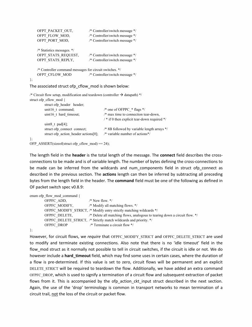
The associated struct ofp_cflow_mod is shown below:
/* Circuit flow setup, modification and teardown (controller datapath) */ struct ofp_cflow_mod { struct ofp_header header; unit16_t command; /* one of OFPPC_* flags */ uint16_t hard_timeout; /* max time to connection tear-down,
/ * if 0 then explicit tear-down required */ uint8_t pad[4]; struct ofp_connect connect; /* 8B followed by variable length arrays */ struct ofp_action_header actions[0]; /* variable number of actions*/
The length field in the header is the total length of the message. The connect field describes the cross‐connections to be made and is of variable length. The number of bytes defining the cross‐connections to be made can be inferred from the wildcards and num_components field in struct ofp_connect as described in the previous section. The actions length can then be inferred by subtracting all preceding bytes from the length field in the header. The command field must be one of the following as defined in OF packet switch spec v0.8.9:
enum ofp_flow_mod_command { OFPFC_ADD, /* New flow. */ OFPFC_MODIFY, /* Modify all matching flows. */ OFPFC_MODIFY_STRICT, /* Modify entry strictly matching wildcards */ OFPFC_DELETE, /* Delete all matching flows, analogous to tearing down a circuit flow. */ OFPFC_DELETE_STRICT, /* Strictly match wildcards and priority. */ OFPFC_DROP /* Terminate a circuit flow */
};
However, for circuit flows, we require that OFPFC_MODIFY_STRICT and OFPFC_DELETE_STRICT are used to modify and terminate existing connections. Also note that there is no ‘idle timeout’ field in the flow_mod struct as it normally not possible to tell in circuit switches, if the circuit is idle or not. We do however include a hard_timeout field, which may find some uses in certain cases, where the duration of a flow is pre‐determined. If this value is set to zero, circuit flows will be permanent and an explicit DELETE_STRICT will be required to teardown the flow. Additionally, we have added an extra command OFPFC_DROP, which is used to signify a termination of a circuit flow and subsequent extraction of packet flows from it. This is accompanied by the ofp_action_ckt_input struct described in the next section. Again, the use of the ‘drop’ terminology is common in transport networks to mean termination of a circuit trail, not the loss of the circuit or packet flow.
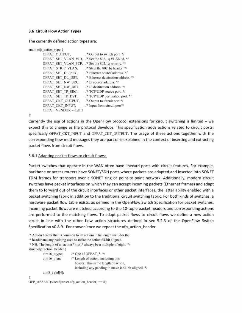
3.6 Circuit Flow Action Types
The currently defined action types are:
enum ofp_action_type { OFPAT_OUTPUT, /* Output to switch port. */ OFPAT_SET_VLAN_VID, /* Set the 802.1q VLAN id. */ OFPAT_SET_VLAN_PCP, /* Set the 802.1q priority. */ OFPAT_STRIP_VLAN, /* Strip the 802.1q header. */ OFPAT_SET_DL_SRC, /* Ethernet source address. */ OFPAT_SET_DL_DST, /* Ethernet destination address. */ OFPAT_SET_NW_SRC, /* IP source address. */ OFPAT_SET_NW_DST, /* IP destination address. */ OFPAT_SET_TP_SRC, /* TCP/UDP source port. */ OFPAT_SET_TP_DST, /* TCP/UDP destination port. */ OFPAT_CKT_OUTPUT, /* Output to circuit port */ OFPAT_CKT_INPUT, /* Input from circuit port*/ OFPAT_VENDOR = 0xffff
};
Currently the use of actions in the OpenFlow protocol extensions for circuit switching is limited – we expect this to change as the protocol develops. This specification adds actions related to circuit ports: specifically OFPAT_CKT_INPUT and OFPAT_CKT_OUTPUT. The usage of these actions together with the corresponding flow mod messages they are part of is explained in the context of inserting and extracting packet flows from circuit flows.
3.6.1 Adapting packet flows to circuit flows:
Packet switches that operate in the WAN often have linecard ports with circuit features. For example, backbone or access routers have SONET/SDH ports where packets are adapted and inserted into SONET TDM frames for transport over a SONET ring or point‐to‐point network. Additionally, modern circuit switches have packet interfaces on which they can accept incoming packets (Ethernet frames) and adapt them to forward out of the circuit interfaces or other packet interfaces, the latter ability enabled with a packet switching fabric in addition to the traditional circuit switching fabric. For both kinds of switches, a hardware packet flow table exists, as defined in the OpenFlow Switch Specification for packet switches. Incoming packet flows are matched according to the 10‐tuple packet headers and corresponding actions are performed to the matching flows. To adapt packet flows to circuit flows we define a new action struct in line with the other flow action structures defined in sec 5.2.3 of the OpenFlow Switch Specification v0.8.9. For convenience we repeat the ofp_action_header
/* Action header that is common to all actions. The length includes the * header and any padding used to make the action 64-bit aligned. * NB: The length of an action *must* always be a multiple of eight. */ struct ofp_action_header {
uint16_t type; /* One of OFPAT_*. */ uint16_t len; /* Length of action, including this
header. This is the length of action, including any padding to make it 64-bit aligned. */
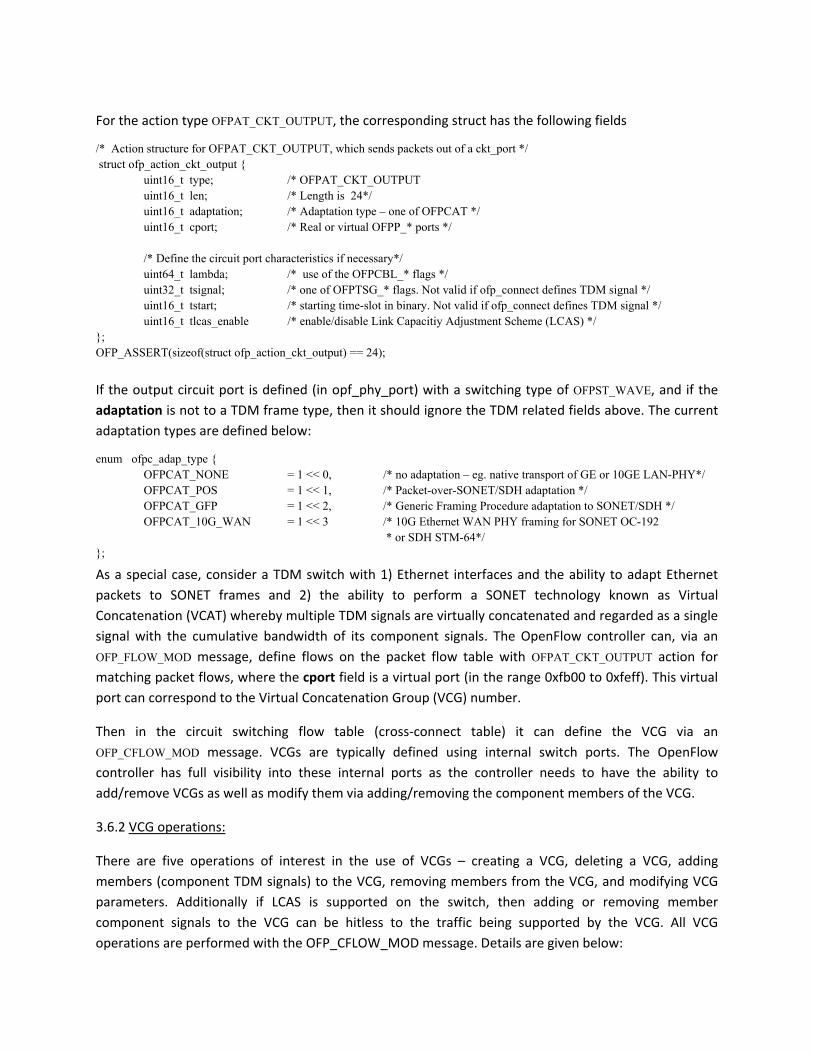
For the action type OFPAT_CKT_OUTPUT, the corresponding struct has the following fields
/* Action structure for OFPAT_CKT_OUTPUT, which sends packets out of a ckt_port */ struct ofp_action_ckt_output { uint16_t type; /* OFPAT_CKT_OUTPUT uint16_t len; /* Length is 24*/ uint16_t adaptation; /* Adaptation type – one of OFPCAT */ uint16_t cport; /* Real or virtual OFPP_* ports */ /* Define the circuit port characteristics if necessary*/ uint64_t lambda; /* use of the OFPCBL_* flags */ uint32_t tsignal; /* one of OFPTSG_* flags. Not valid if ofp_connect defines TDM signal */ uint16_t tstart; /* starting time-slot in binary. Not valid if ofp_connect defines TDM signal */ uint16_t tlcas_enable /* enable/disable Link Capacitiy Adjustment Scheme (LCAS) */ }; OFP_ASSERT(sizeof(struct ofp_action_ckt_output) == 24);
If the output circuit port is defined (in opf_phy_port) with a switching type of OFPST_WAVE, and if the adaptation is not to a TDM frame type, then it should ignore the TDM related fields above. The current adaptation types are defined below:
enum ofpc_adap_type { OFPCAT_NONE = 1 << 0, /* no adaptation – eg. native transport of GE or 10GE LAN-PHY*/ OFPCAT_POS = 1 << 1, /* Packet-over-SONET/SDH adaptation */ OFPCAT_GFP = 1 << 2, /* Generic Framing Procedure adaptation to SONET/SDH */ OFPCAT_10G_WAN = 1 << 3 /* 10G Ethernet WAN PHY framing for SONET OC-192
* or SDH STM-64*/ };
As a special case, consider a TDM switch with 1) Ethernet interfaces and the ability to adapt Ethernet packets to SONET frames and 2) the ability to perform a SONET technology known as Virtual Concatenation (VCAT) whereby multiple TDM signals are virtually concatenated and regarded as a single signal with the cumulative bandwidth of its component signals. The OpenFlow controller can, via an OFP_FLOW_MOD message, define flows on the packet flow table with OFPAT_CKT_OUTPUT action for matching packet flows, where the cport field is a virtual port (in the range 0xfb00 to 0xfeff). This virtual port can correspond to the Virtual Concatenation Group (VCG) number.
Then in the circuit switching flow table (cross‐connect table) it can define the VCG via an OFP_CFLOW_MOD message. VCGs are typically defined using internal switch ports. The OpenFlow controller has full visibility into these internal ports as the controller needs to have the ability to add/remove VCGs as well as modify them via adding/removing the component members of the VCG.
3.6.2 VCG operations:
There are five operations of interest in the use of VCGs – creating a VCG, deleting a VCG, adding members (component TDM signals) to the VCG, removing members from the VCG, and modifying VCG parameters. Additionally if LCAS is supported on the switch, then adding or removing member component signals to the VCG can be hitless to the traffic being supported by the VCG. All VCG operations are performed with the OFP_CFLOW_MOD message. Details are given below:
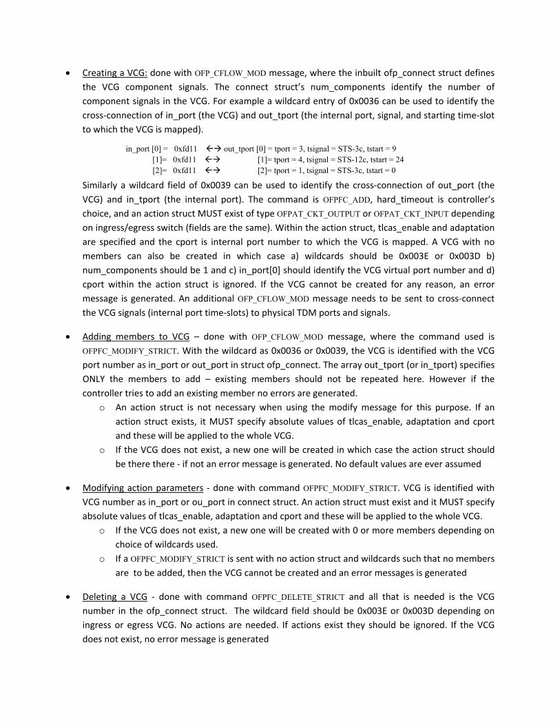
• Creating a VCG: done with OFP_CFLOW_MOD message, where the inbuilt ofp_connect struct defines the VCG component signals. The connect struct’s num_components identify the number of component signals in the VCG. For example a wildcard entry of 0x0036 can be used to identify the cross‐connection of in_port (the VCG) and out_tport (the internal port, signal, and starting time‐slot to which the VCG is mapped).
Similarly a wildcard field of 0x0039 can be used to identify the cross‐connection of out_port (the VCG) and in_tport (the internal port). The command is OFPFC_ADD, hard_timeout is controller’s choice, and an action struct MUST exist of type OFPAT_CKT_OUTPUT or OFPAT_CKT_INPUT depending on ingress/egress switch (fields are the same). Within the action struct, tlcas_enable and adaptation are specified and the cport is internal port number to which the VCG is mapped. A VCG with no members can also be created in which case a) wildcards should be 0x003E or 0x003D b) num_components should be 1 and c) in_port[0] should identify the VCG virtual port number and d) cport within the action struct is ignored. If the VCG cannot be created for any reason, an error message is generated. An additional OFP_CFLOW_MOD message needs to be sent to cross‐connect the VCG signals (internal port time‐slots) to physical TDM ports and signals.
• Adding members to VCG – done with OFP_CFLOW_MOD message, where the command used is OFPFC_MODIFY_STRICT. With the wildcard as 0x0036 or 0x0039, the VCG is identified with the VCG port number as in_port or out_port in struct ofp_connect. The array out_tport (or in_tport) specifies ONLY the members to add – existing members should not be repeated here. However if the controller tries to add an existing member no errors are generated.
o An action struct is not necessary when using the modify message for this purpose. If an action struct exists, it MUST specify absolute values of tlcas_enable, adaptation and cport and these will be applied to the whole VCG.
o If the VCG does not exist, a new one will be created in which case the action struct should be there there ‐ if not an error message is generated. No default values are ever assumed
• Modifying action parameters ‐ done with command OFPFC_MODIFY_STRICT. VCG is identified with VCG number as in_port or ou_port in connect struct. An action struct must exist and it MUST specify absolute values of tlcas_enable, adaptation and cport and these will be applied to the whole VCG.
o If the VCG does not exist, a new one will be created with 0 or more members depending on choice of wildcards used.
o If a OFPFC_MODIFY_STRICT is sent with no action struct and wildcards such that no members are to be added, then the VCG cannot be created and an error messages is generated
• Deleting a VCG ‐ done with command OFPFC_DELETE_STRICT and all that is needed is the VCG number in the ofp_connect struct. The wildcard field should be 0x003E or 0x003D depending on ingress or egress VCG. No actions are needed. If actions exist they should be ignored. If the VCG does not exist, no error message is generated
• Deleting members from VCG – done with command OFPFC_DELETE_STRICT. VCG is identified with VCG number as in_port or out_port in ofp_connect. The wildcard field should not be 0x003E or 0x003D otherwise the entire VCG will be deleted. The array out_tport (or in_tport) specifies ONLY the members to delete – should be an existing member but if not, then no error message is generated. An action struct should not be included in the delete message – if actions exist they should be ignored. Deleting the last member of the VCG should NOT delete the VCG. If the VCG does not exist no error messages are generated.
In general, when adding or modifying members, the time‐slots specified MUST be free – if not an error is generated. In other words, timeslots must be released (deleted) before being re‐assigned. When making regular TDM to TDM time‐slot crossconnects, only ADD and DELETE_STRICT apply.
3.6.3 Extracting Packet Flows from Circuit Flows:
To go back from circuit to packet flows, we need to terminate the circuit flow, de‐encapsulate the payload if an adaption was used and send out the packets to packet interfaces or do flow matching if a packet switching fabric exists in the same switch. Often in a circuit switch the termination of a circuit flow is also accomplished by defining a cross‐connection to a ‘Drop’ port. This can be accomplished with an OFP_CFLOW_MOD message with associated command OFPFC_DROP. Note that this use of ‘drop’ does not have the same meaning as ‘dropping a packet’. A cross‐connection to a Drop port can also be defined with a struct ofp_connect with an associated action struct as defined below:
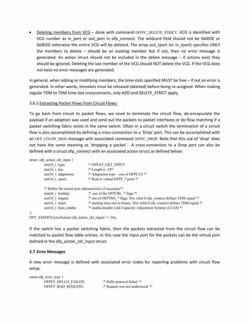
struct ofp_action_ckt_input { uint16_t type; /* OFPAT_CKT_INPUT uint16_t len; /* Length is 24*/ uint16_t adaptation; /* Adaptation type – one of OFPCAT */ uint16_t cport; /* Real or virtual OFPP_* ports */
/* Define the circuit port characteristics if necessary*/
uint64_t lambda; /* use of the OFPCBL_* flags */ uint32_t tsignal; /* one of OFPTSG_* flags. Not valid if ofp_connect defines TDM signal */ uint16_t tstart; /* starting time-slot in binary. Not valid if ofp_connect defines TDM signal */ uint16_t tlcas_enable /* enable/disable Link Capacitiy Adjustment Scheme (LCAS) */ }; OFP_ASSERT(sizeof(struct ofp_action_ckt_input) == 24);
If the switch has a packet switching fabric, then the packets extracted from the circuit flow can be matched to packet flow table entries. In this case the input port for the packets can be the virtual port defined in the ofp_action_ckt_input struct.
3.7 Error Messages
A new error message is defined with associated error codes for reporting problems with circuit flow setup.
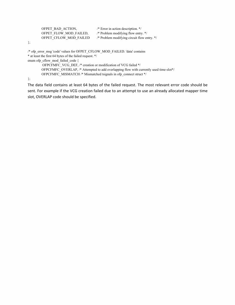
enum ofp_error_type { OFPET_HELLO_FAILED, /* Hello protocol failed. */ OFPET_BAD_REQUEST, /* Request was not understood. */
OFPET_BAD_ACTION, /* Error in action description. */ OFPET_FLOW_MOD_FAILED, /* Problem modifying flow entry. */ OFPET_CFLOW_MOD_FAILED /* Problem modifying circuit flow entry. */ }; /* ofp_error_msg 'code' values for OFPET_CFLOW_MOD_FAILED. 'data' contains * at least the first 64 bytes of the failed request. */ enum ofp_cflow_mod_failed_code { OFPCFMFC_VCG_DEF, /* creation or modification of VCG failed */ OFPCFMFC_OVERLAP, /* Attempted to add overlapping flow with currently used time-slot*/ OFPCFMFC_MISMATCH /* Mismatched tsignals in ofp_connect struct */ };
The data field contains at least 64 bytes of the failed request. The most relevant error code should be sent. For example if the VCG creation failed due to an attempt to use an already allocated mapper time slot, OVERLAP code should be specified.