Instructions for Safe Operation After washing hands, place hands approximately 4 to 6 inches (100 to 150 mm) under hand dryer nozzle until dry. The dryer is activated by an infrared sensor. The dryer operates as long as hands are below the nozzle. There is a maximum 35 second running time with a safety override feature if hands are not removed. The dryer incorporates a non‑self‑resetting thermal cut‑out that is reset by disconnection of the supply mains. CPC models are equipped with Cold Plasma Clean ® technology. EXTREMEAIR High Speed Hand Dryer Owner’s Manual Instructions apply to the following models: CPC9 GXT9 EXT7 CPC9‑M GXT9‑M EXT7‑M CPC9‑BG GXT9‑BG EXT7‑BG CPC9‑C GXT9‑C EXT7‑C CPC9‑SS GXT9‑SS EXT7‑SS User Maintenance Instructions DO NOT spray water or cleaning solvents through dryer vents. DO NOT use abrasive, chlorinated, or highly alkaline cleaners. DO NOT use oil based cleaners. Cleaning should be preformed on a regular basis at least twice per year. Clean cover with a mild soap or detergent and warm water, using a soft cloth or sponge. It is not necessary to disconnect power for cleaning. EXTREMEAIR ® MFD by AMERICAN DRYER, INC. 33067 INDUSTRIAL ROAD, LIVONIA, MI 48150, U.S.A. Telephone (734) 421‑2400 • Fax (734) 421‑5580 americandryer.com • Email: [email protected]Revised October 2014 distributed by RESTROOM DIRECT 70 4 . 937 . 2673 www. RestroomDirect .com
Transcript
Instructions for Safe Operation
After washing hands, place hands approximately 4 to 6 inches (100 to 150 mm) under hand dryer nozzle until dry. The dryer is activated by an infrared sensor. The dryer operates as long as hands are below the nozzle. There is a maximum 35 second running time with a safety override feature if hands are not removed.
The dryer incorporates a non‑self‑resetting thermal cut‑out that is reset by disconnection of the supply mains.
CPC models are equipped with Cold Plasma Clean® technology.
eXtremeAir High Speed Hand DryerOwner’s Manual
Instructions apply to the following models:CPC9 GXT9 EXT7 CPC9‑M GXT9‑M EXT7‑MCPC9‑BG GXT9‑BG EXT7‑BG CPC9‑C GXT9‑C EXT7‑CCPC9‑SS GXT9‑SS EXT7‑SS
User Maintenance Instructions
DO NOT spray water or cleaning solvents through dryer vents. DO NOT use abrasive, chlorinated, or highly alkaline cleaners. DO NOT use oil based cleaners.
Cleaning should be preformed on a regular basis at least twice per year.
Clean cover with a mild soap or detergent and warm water, using a soft cloth or sponge.
It is not necessary to disconnect power for cleaning.
eXtremeAir®
MFD by AMERICAN DRYER, INC.33067 INDUSTRIAL ROAD, LIVONIA, MI 48150, U.S.A.Telephone (734) 421‑2400 • Fax (734) 421‑5580americandryer.com • Email: [email protected] October 2014
distributed by RESTROOM DIRECT 704 . 937. 2673 www.RestroomDirect .com
Installation Instructions
1. Remove cover by removing (2) tamper‑proof screws using security wrench supplied. Pull cover directly toward you. IMPORTANT: Save Security Wrench.
2. Dryers should be placed at least 2 feet (61cm) apart and at least 12” (30cm) from washbasin. Do not install dryer over washbasin. Dryers should be at least 18” (46cm) above any projection which may interfere with the operation of the automatic sensor.
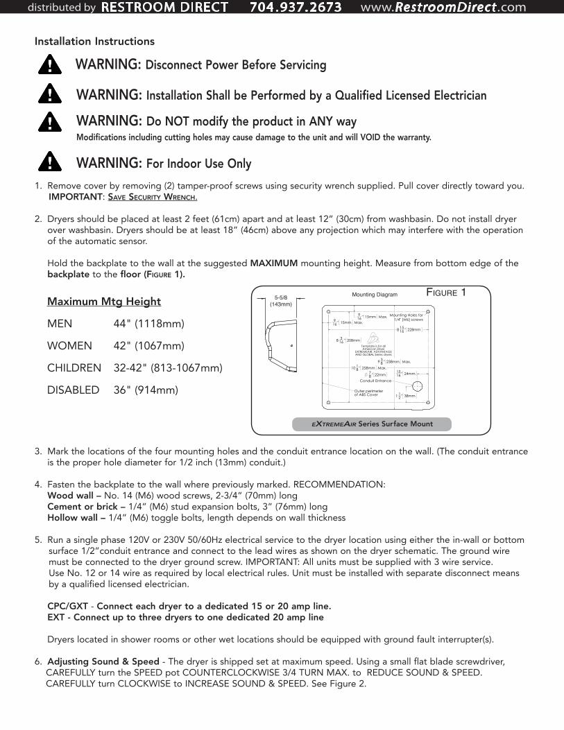
Hold the backplate to the wall at the suggested MAXIMUM mounting height. Measure from bottom edge of the backplate to the floor (Figure 1).
3. Mark the locations of the four mounting holes and the conduit entrance location on the wall. (The conduit entrance is the proper hole diameter for 1/2 inch (13mm) conduit.)
4. Fasten the backplate to the wall where previously marked. RECOMMENDATION: Wood wall – No. 14 (M6) wood screws, 2‑3/4” (70mm) long Cement or brick – 1/4” (M6) stud expansion bolts, 3” (76mm) long Hollow wall – 1/4” (M6) toggle bolts, length depends on wall thickness
5. Run a single phase 120V or 230V 50/60Hz electrical service to the dryer location using either the in‑wall or bottom surface 1/2”conduit entrance and connect to the lead wires as shown on the dryer schematic. The ground wire must be connected to the dryer ground screw. IMPORTANT: All units must be supplied with 3 wire service. Use No. 12 or 14 wire as required by local electrical rules. Unit must be installed with separate disconnect means by a qualified licensed electrician.
CPC/GXT ‑ Connect each dryer to a dedicated 15 or 20 amp line. EXT - Connect up to three dryers to one dedicated 20 amp line
Dryers located in shower rooms or other wet locations should be equipped with ground fault interrupter(s).
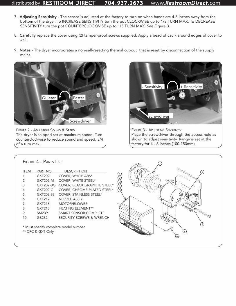
6. Adjusting Sound & Speed ‑ The dryer is shipped set at maximum speed. Using a small flat blade screwdriver, CAREFULLY turn the SPEED pot COUNTERCLOCKWISE 3/4 TURN MAX. to REDUCE SOUND & SPEED. CAREFULLY turn CLOCKWISE to INCREASE SOUND & SPEED. See Figure 2.
WARNING: Disconnect Power Before Servicing
WARNING: Installation Shall be Performed by a Qualified Licensed Electrician
Maximum Mtg Height
MEN 44" (1118mm)
WOMEN 42" (1067mm)
CHILDREN 32‑42" (813‑1067mm)
DISABLED 36" (914mm)
WARNING: Do NOT modify the product in ANY wayModifications including cutting holes may cause damage to the unit and will VOID the warranty.
5-5/8(143mm)
eXtremeAir Series Surface Mount
WARNING: For Indoor Use Only
Figure 1Mounting Diagram
10 18 " 258mm Max.
9 38 " 238mm Max.
78 " 22mm
Conduit Entrance
8 316 " 208mm
916 " 15mm Max.
916 " 15mm Max.
8 1516 " 228mm
1 12 " 38mm
1516 " 24mm
Mounting Holes for1/4" [M6] screws
Template is for all American Dryer
EXTREMEAIR, ADVANTAGE AND GLOBAL Series dryers
Outer perimeterof ABS Cover
Revised 10/06/2014
distributed by RESTROOM DIRECT 704 . 937. 2673 www.RestroomDirect .com
7. Adjusting Sensitivity ‑ The sensor is adjusted at the factory to turn on when hands are 4‑6 inches away from the bottom of the dryer. To INCREASE SENSITIVITY turn the pot CLOCKWISE up to 1/3 TURN MAX. To DECREASE SENSITIVITY turn the pot COUNTERCLOCKWISE up to 1/3 TURN MAX. See Figure 3.
8. Carefully replace the cover using (2) tamper‑proof screws supplied. Apply a bead of caulk around edges of cover to wall.
9. Notes ‑ The dryer incorporates a non‑self‑resetting thermal cut‑out that is reset by disconnection of the supply mains.
Figure 2 - Adjusting sound & speedThe dryer is shipped set at maximum speed. Turn counterclockwise to reduce sound and speed. 3/4 of a turn max.
Screwdriver
Quieter Faster
Figure 3 - Adjusting sensitivityPlace the screwdriver through the access hole as shown to adjust sensitivity. Range is set at the factory for 4 ‑ 6 inches (100‑150mm).
* Must specify complete model number** CPC & GXT Only
7
8
9
6
10
12345
distributed by RESTROOM DIRECT 704 . 937. 2673 www.RestroomDirect .com
Service Instructions
Each component used in your dryer has been designed to provide years of trouble‑free service. However, if trouble should develop, it can normally be located by visual examination. Removal or replacement of most parts is simple and can be done without special tools.
IF THE DRYER WON’T TURN ON: Check electrical service, circuit breaker. Make sure proper voltage is being supplied to the dryer. Check for loose or disconnected terminals to sensor. INCREASE sensitivity (Figure 3) by inserting a flat‑blade screwdriver through the hole and into the pot to CAREFULLY turn the adjustment pot located on the sensor CLOCKWISE 1/3 turn MAX. If necessary, replace sensor.
IF DRYER WILL NOT SHUT OFF: Make certain black foam is attached to lens and lens is clean. If damaged, replace. DECREASE sensitivity (Figure 3) by inserting a flat‑blade screwdriver through the hole and into the pot to CAREFULLY turn the adjustment pot located on the sensor COUNTER‑CLOCKWISE, 1/3 turn MAX. If necessary, replace sensor.
CPC AND GXT ONLY - IF COLD AIR IS COMING FROM THE NOZZLE:Turn off breaker for 30 seconds to reset thermostat. If necessary, inspect heating element by unfastening blower housing from backplate (3 screws). Remove heating element from blower housing to inspect for damage. Replace if necessary.
IF NO AIR IS COMING FROM THE NOZZLE:If the dryer also trips the circuit breaker, replace the motor/blower assembly by unfastening the blower housing from the backplate (3 screws) and remove the inlet shield. Otherwise, replace the sensor.
COLD PLASMA GENERATOR:The cold plasma generator is maintenance free. There are no chemicals to refill and no filters to change.
eXtremeAir LIMITED WARRANTY
All parts of the eXtremeAir models are warranted to the original consumer purchaser to be free from defects in material workmanship for a period of five (5) years from the date of purchase from the manufacturer. All models outside of the U.S.A. one (1) year. We will replace, during the warranty period, any warranted part which proves defective in material and or workmanship under normal installation, use, and service, excluding normal wear. Replacement parts can be obtained by returning the part, TRANSPORTATION CHARGES PREPAID. You must notify factory prior to returning part or dryer. Any damage to this dryer as a result of misuse, abuse, neglect, accident, improper installation, unauthorized repairs, or any other use violative of instructions furnished by us WILL VOID THIS WARRANTY. THIS LIMITED WARRANTY IS THE SOLE WARRANTY ON OUR PRODUCTS, AND WE DISCLAIM AND EXCLUDE ANY AND ALL OTHER WARRANTIED, EXPRESS OR IMPLIED, INCLUDING ANY IMPLIED WARRANTIES OF MERCHANTABILITY OR FITNESS FOR A PARTICULAR PURPOSE. OUR LIABILITY SHALL NOT EXCEED IN ANY EVENT THE REPLACEMENT OR SALE PRICE OF THE ALLEGEDLY NONCONFORMING PRODUCT AND SHALL EXCLUDE LABOR CHARGES. TO THE EXTENT PERMITTED BY LAW WE SHALL NOT BE LIABLE FOR ANY LOSS, COST, EXPENSE, OR INCIDENTAL OR CONSEQUENTIAL DAMAGES OF ANY KIND. WHETHER BASED UPON WARRANTY (EXPRESS OR IMPLIED), CONTRACT, NEGLIGENCE OR STRICT LIABILITY AND ARISING IN ANY WAY IN CONNECTION WITH THE DESIGN, MANUFACTURE, SALE, USE OR REPAIR OF THE PRODUCT.
WARNING: Disconnect Power Before Servicing
WARNING: Installation Shall be Performed by a Qualified Licensed Electrician
distributed by RESTROOM DIRECT 704 . 937. 2673 www.RestroomDirect .com