25
eZ430-RF2500-SEH Solar Energy Harvesting Development Tool User's Guide Literature Number: SLAU273D January 2009–Revised July 2013
eZ430-RF2500-SEH Solar Energy HarvestingDevelopment Tool
User's Guide
Literature Number: SLAU273D
January 2009–Revised July 2013

Contents
Preface ....................................................................................................................................... 4
1 eZ430-RF2500-SEH Overview ................................................................................................ 51.1 Solar Energy Harvesting ................................................................................................... 51.2 Kit Contents, eZ430-RF2500-SEH ........................................................................................ 61.3 Working With the eZ430-RF2500 ......................................................................................... 7
2 Getting Started ................................................................................................................... 82.1 Prepare Solar Energy Harvester Module ................................................................................ 82.2 Install Sensor Monitor Application and Drivers .......................................................................... 82.3 Connect Hardware .......................................................................................................... 82.4 Install Code Composer Studio ............................................................................................ 92.5 Install the eZ430-RF2500-SEH Sensor Monitor Firmware Source ................................................... 9
3 Solar Energy Harvester Module (SEH-01) ............................................................................. 103.1 Functional Description .................................................................................................... 103.2 Solar Energy Harvester Module (SEH-01) Figure and Description ................................................. 103.3 Solar Energy Harvester Module (SEH-01) Operating Characteristics .............................................. 123.4 Solar Energy Harvester Module (SEH-01) Circuit Schematic ....................................................... 123.5 Pulse Discharge Current for a Wireless End Device ................................................................. 13
4 eZ430-RF2500-SEH Sensor Monitor ..................................................................................... 144.1 MSP430 Firmware ......................................................................................................... 14
4.1.1 Downloading Firmware to the MSP430 ........................................................................ 144.2 PC Sensor Monitor Application .......................................................................................... 15
4.2.1 Energy Awareness ............................................................................................... 154.2.2 Remaining Transmissions ....................................................................................... 154.2.3 Menu Bar .......................................................................................................... 154.2.4 PC Sensor Monitor Application Source Code ................................................................ 18
A Frequently Asked Questions ............................................................................................... 19A.1 FAQs ........................................................................................................................ 19
2 Contents SLAU273D–January 2009–Revised July 2013Submit Documentation Feedback
Copyright © 2009–2013, Texas Instruments Incorporated

www.ti.com
List of Figures
1-1. eZ430-RF2500-SEH ........................................................................................................ 6
1-2. eZ430-RF2500-SEH Development Tool Features...................................................................... 7
3-1. Solar Energy Harvester Module (SEH-01) Block Diagram........................................................... 10
3-2. Solar Energy Harvester Module Connections ......................................................................... 11
3-3. Solar Energy Harvester Module Schematic............................................................................ 12
4-1. eZ430-RF2500-SEH Sensor Monitor ................................................................................... 15
4-2. Menu Bar ................................................................................................................... 16
4-3. Console Window........................................................................................................... 16
4-4. Real-Time Node Data from the Graph Window ....................................................................... 17
4-5. Configurations Window ................................................................................................... 17
List of Tables
3-1. SEH-01 Operating Characteristics ...................................................................................... 12
3SLAU273D–January 2009–Revised July 2013 List of FiguresSubmit Documentation Feedback
Copyright © 2009–2013, Texas Instruments Incorporated

PrefaceSLAU273D–January 2009–Revised July 2013
Read This First
If You Need Assistance
If you have any feedback or questions, support for the MSP430 device and the eZ430-RF2500 is providedby the Texas Instruments Product Information Center (PIC) and the TI E2E Forum (http://e2e.ti.com).Contact information for the PIC can be found on the TI web site at http://support.ti.com. Additional device-specific information can be found on the MSP430 web site http://www.ti.com/msp430.
NOTE: Support for the Solar Energy Harvesting Module
The Solar Energy Harvester module (SEH-01) is a product of Cymbet Corporation. For anyquestions specifically on the SEH-01 module, contact Cymbet at www.cymbet.com or +1-763-633-1780.
Related Documentation from Texas Instruments
The primary sources of MSP430 information are the device-specific data sheets and user's guides. Themost up-to-date versions of the user's guide documents available at the time of production have beenprovided on the CD-ROM included with this tool. However, the most current information is found athttp://www.ti.com/msp430.
Information specific to the eZ430-RF2500-SEH development tool can be found athttp://www.ti.com/tool/ez430-rf2500-seh.
MSP430 device user's guides and the FET user's guide (SLAU157) may be accessed on the included CD-ROM under the User's Guides section. The FET user's guide includes detailed information on setting up aproject for the MSP430 using Code Composer Studio.
SimpliciTI is a trademark of Texas Instruments.All other trademarks are the property of their respective owners.
4 Read This First SLAU273D–January 2009–Revised July 2013Submit Documentation Feedback
Copyright © 2009–2013, Texas Instruments Incorporated

Chapter 1SLAU273D–January 2009–Revised July 2013
eZ430-RF2500-SEH Overview
1.1 Solar Energy Harvesting
The eZ430-RF2500-SEH is a complete Solar Energy Harvesting development kit to help create aperpetually powered wireless sensor network based on the ultra-low-power MSP430 microcontroller.
The Solar Energy Harvesting module includes a high-efficiency solar (2.25 in x 2.25 in) panel optimized foroperating indoors under low-intensity florescent lights, which provides enough power to run a wirelesssensor application with no additional batteries. Inputs are also available for external energy harvesterssuch as thermal, piezoelectric, or another solar panel.
The system also manages and stores additional energy in a pair of thin-film rechargeable EnerChipswhich are capable of delivering enough power for 400+ transmissions. The EnerChips act as an energybuffer that stores the energy while the application is sleeping and has light available to harvest. Thebatteries are environmentally friendly and can be recharged thousands of times. They also have a verylow self discharge, which is vital for a no-power, energy harvesting system.
The eZ430-RF2500 is used to run the energy harvesting application. It is a complete USB-based MSP430wireless development tool and provides all the hardware and software necessary to use theMSP430F2274 microcontroller and CC2500 2.4-GHz wireless transceiver. It includes a USB debugginginterface that allows for real-time, in-system debugging and programming for the MSP430, and it is alsothe interface to transfer data to a PC from the wireless system.
The integrated temperature and RF signal strength indicators can be used to monitor the environment,and many external sensors can be used to collect additional data.
eZ430-RF2500-SEH Features• Efficient solar energy harvesting module for the eZ430-RF2500
• Battery-less operation
• Works in low ambient light
• 400+ transmissions in dark
• Adaptable to any RF network or sensor input
• Inputs available for external harvesters (such as thermal or piezoelectric)
• USB debugging and programming interface with an application backchannel to the PC
• 18 available analog and communications input/output pins
• Highly integrated, ultra-low-power MSP430 MCU with 16-MHz performance
• Two green and red LEDs for visual feedback
• Interruptible push button for user feedback
5SLAU273D–January 2009–Revised July 2013 eZ430-RF2500-SEH OverviewSubmit Documentation Feedback
Copyright © 2009–2013, Texas Instruments Incorporated

Kit Contents, eZ430-RF2500-SEH www.ti.com
Figure 1-1. eZ430-RF2500-SEH
1.2 Kit Contents, eZ430-RF2500-SEH• Two eZ430-RF2500T wireless target boards
• One eZ430-RF USB debugging interface
• One AAA battery pack with expansion board (batteries included)
• One SEH-01-DK Solar Energy Harvesting Board
• One MSP430 Development Tool CD containing documentation and development software
– eZ430-RF2500-SEH Demo and Source Code (SLAC219)
– eZ430-RF2500-SEH Development Tool User's Guide (SLAU273)
– eZ430-RF2500 Development Tool User's Guide (SLAU227)
– MSP430x2xx Family User's Guide (SLAU144)
– Code Composer Studio v5.4 for MSP430 User's Guide (SLAU157)
– Code Composer Studio v5.4 (CCSTUDIO)
NOTE: For the latest software and documentation, go to http://www.ti.com/tool/ez430-rf2500-seh.
6 eZ430-RF2500-SEH Overview SLAU273D–January 2009–Revised July 2013Submit Documentation Feedback
Copyright © 2009–2013, Texas Instruments Incorporated

www.ti.com Working With the eZ430-RF2500
Figure 1-2. eZ430-RF2500-SEH Development Tool Features
1.3 Working With the eZ430-RF2500
For detailed information on the eZ430-RF2500 Wireless Development Tool, see its user's guide—theeZ430-RF2500 Development Tool User's Guide (SLAU227) includes the following information that is notcovered in this document:
• eZ430-RF2500T target board pinout
• MSP430F2274 and CC2500 specifications
• List of eZ430 emulator supported devices
• MSP430 application UART description
• Detailed eZ430-RF2500 hardware installation
• eZ430-RF2500 FAQ
• eZ430-RF2500 schematics and layout
7SLAU273D–January 2009–Revised July 2013 eZ430-RF2500-SEH OverviewSubmit Documentation Feedback
Copyright © 2009–2013, Texas Instruments Incorporated

Chapter 2SLAU273D–January 2009–Revised July 2013
Getting Started
2.1 Prepare Solar Energy Harvester Module1. Remove the Battery Enable jumper, J8 (see Figure 1-2).
2. Place the solar module in a well lit location for at least a few minutes prior to use. In average indoorlighting, it may take up to one hour to fully charge the system. However, approximately five minutesshould be sufficient for initial startup.
2.2 Install Sensor Monitor Application and Drivers1. Download the eZ430-RF2500-SEH Demo and Source Code (SLAC219) from the eZ430-RF2500-SEH
Development Tool web page or from the included CD.
2. Unzip the archive and run SEH-demo-setup-vx.x.exe.
3. Respond to the prompts to install the application.
4. Open the eZ430-RF2500-SEH Sensor Monitor program. A shortcut is available on the Desktop and inthe Start Menu under Programs > Texas Instruments > eZ430-RF2500-SEH Sensor Monitor.
2.3 Connect Hardware1. Insert the eZ430-RF2500 into a USB port on the PC. This acts as the Access Point.
If prompted for the driver for the MSP430 Application UART, allow Windows to 'Install the softwareautomatically'. This is only possible if the Sensor Monitor has already been installed.
For more information, see Section 14, Detailed Hardware Installation Guide in the eZ430-RF2500user's guide (SLAU227).
The Sensor Monitor PC application should now detect the MSP430 Application UART on theappropriate COM port, and the center bubble in the program blinks once per second.
2. Attach the second eZ430-RF2500T target board to the Solar Energy Harvesting Module (SEH-01) onconnector J1. All components on the boards should be face up. A second bubble should appear in theSensor Monitor window representing the End Device. If the second bubble does not appear, place theSEH-01 directly under a bright light for a few seconds and try again. Also try using the battery pack tomake sure the hardware is programmed properly.
3. By default, the End Device transmits every 10 seconds. Push the button on the End Device to changethe transmission duty cycle in the following intervals: 10 seconds, 20 seconds, 40 seconds, 2 minutes,4 minutes, and 5 seconds.
4. Cover the solar panel to force the system run from the stored energy. The number of remainingtransmissions is displayed.
5. When finished, remove the eZ430-RF2500T End Device from the SEH-01 module, replace jumper onJ8, and close any open programs.
For troubleshooting tips, see Frequently Asked Questions.
8 Getting Started SLAU273D–January 2009–Revised July 2013Submit Documentation Feedback
Copyright © 2009–2013, Texas Instruments Incorporated
www.ti.com Install Code Composer Studio
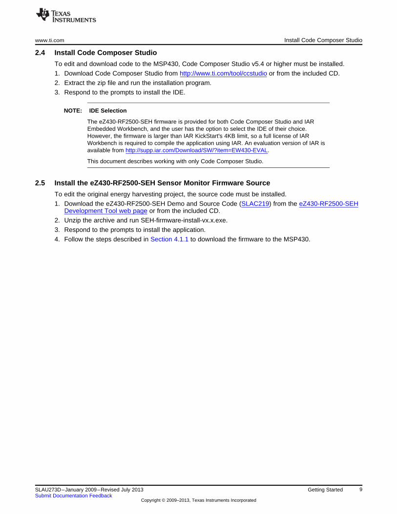
2.4 Install Code Composer Studio
To edit and download code to the MSP430, Code Composer Studio v5.4 or higher must be installed.
1. Download Code Composer Studio from http://www.ti.com/tool/ccstudio or from the included CD.
2. Extract the zip file and run the installation program.
3. Respond to the prompts to install the IDE.
NOTE: IDE Selection
The eZ430-RF2500-SEH firmware is provided for both Code Composer Studio and IAREmbedded Workbench, and the user has the option to select the IDE of their choice.However, the firmware is larger than IAR KickStart's 4KB limit, so a full license of IARWorkbench is required to compile the application using IAR. An evaluation version of IAR isavailable from http://supp.iar.com/Download/SW/?item=EW430-EVAL.
This document describes working with only Code Composer Studio.
2.5 Install the eZ430-RF2500-SEH Sensor Monitor Firmware Source
To edit the original energy harvesting project, the source code must be installed.
1. Download the eZ430-RF2500-SEH Demo and Source Code (SLAC219) from the eZ430-RF2500-SEHDevelopment Tool web page or from the included CD.
2. Unzip the archive and run SEH-firmware-install-vx.x.exe.
3. Respond to the prompts to install the application.
4. Follow the steps described in Section 4.1.1 to download the firmware to the MSP430.
9SLAU273D–January 2009–Revised July 2013 Getting StartedSubmit Documentation Feedback
Copyright © 2009–2013, Texas Instruments Incorporated

PhotovoltaicCell
BoostConverter
ChargeControl
Connector
PowerManagement
(2) EnerChipCBC050
ControlLines VOUT
Chapter 3SLAU273D–January 2009–Revised July 2013
Solar Energy Harvester Module (SEH-01)
3.1 Functional Description
The core technology behind the Solar Energy Harvesting module is the photovoltaic or solar cell thatconverts ambient light into electrical energy. The energy from the solar cell must be converted, managedand stored. This process is handled by the EnerChip EH CBC5300, the small DIP mounted board on theSolar Energy Harvesting Module (SEH-01). A boost converter is used to increase the voltage from thesolar cell to a sufficient level to charge the thin-film battery and run the rest of the system.
The Charge Control block continuously monitors the output of the boost converter. If the output of theboost converter falls below the voltage needed to charge the EnerChip, the charge controller disconnectsthe boost converter from the system to prevent back powering the boost converter in low light conditions.
The Power Management block prevents the EnerChip from discharging too deeply in low-light conditionsor under abnormally high current loads. It also ensures that the load is powered up with a smooth power-on transition. The Power Management block has a control line, CHARGE, which indicates to the MSP430that the solar energy harvester is actively charging the EnerChip. The control line input, BATOFF, isavailable for the MSP430 to isolate itself from the EnerChip to conserve battery life in prolonged low-lightconditions.
The Solar Energy Harvesting Module features two EnerChip batteries mounted on the board with a 100-µAhr capacity and a 1000-µF capacitor for high-current pulses during wireless transmissions.
Using the power management status and control signals on the SEH-01, the firmware on the MSP430 hasbeen written to make the application 'Energy Aware' to maximize the overall lifetime of the system.
Figure 3-1. Solar Energy Harvester Module (SEH-01) Block Diagram
3.2 Solar Energy Harvester Module (SEH-01) Figure and Description
Figure 3-2 shows the connections to the Solar Energy Harvester module.
10 Solar Energy Harvester Module (SEH-01) SLAU273D–January 2009–Revised July 2013Submit Documentation Feedback
Copyright © 2009–2013, Texas Instruments Incorporated

J1 Connector for TI ED
Pin Number(s) Description
1
2
3
4
5
6
Connector Type: Rt Angle SIP
BATOFF
GND
Not Connected
Not Connected
VOUT2
Charge
J5 Connector for User
Pin Number(s) Description
1
2
3
4
5
Connector Type: Upright SIP
Charge
BATOFF
VBAT
GND
VOUT2
PT1 Connector
Pin Number(s) Description
1
2
Connector Type: Trace Vias
Piezo input 2
Piezo input 1
J8 Connector
Pin Number(s) Description
1
2
Connector Type: Trace Vias
GND
Positive input
J7 Connector
Pin Number(s) Description
1
Connector Type: Trace
Cut trace to useexternal source
Solar Panel
PT1
J7 J8
EH
Module
J5
1
J1
1
www.ti.com Solar Energy Harvester Module (SEH-01) Figure and Description
Figure 3-2. Solar Energy Harvester Module Connections
J1 Connector: Connection to the eZ430-RF2500T target board.
J5 Connector: Alternate connection point to power an external device or for measuring SEH-01 outputlevels.
J7 Connector: Trace to cut if an alternate solar panel is connected to J8.
J8 Jumper: Battery enable jumper—the shunt must be removed before the module is charged. Thisconnector can also be used to connect an alternate solar panel to the SEH-01.
PT1 Connector: An alternate piezoelectric energy harvesting transducer can be connected. It can beconnected in parallel with the SEH-01 solar panel by leaving J7 intact or the piezoelectric transducer canbe used standalone by cutting the J7 trace.
CAUTION
The EnerChip EH CBC5300 module is mounted on a DIP socket that isremovable from the Solar Energy Harvesting (SEH-01) board. The pins on theCBC5300 are fragile and care must be taken when removing the module.
11SLAU273D–January 2009–Revised July 2013 Solar Energy Harvester Module (SEH-01)Submit Documentation Feedback
Copyright © 2009–2013, Texas Instruments Incorporated
Solar Energy Harvester Module (SEH-01) Operating Characteristics www.ti.com
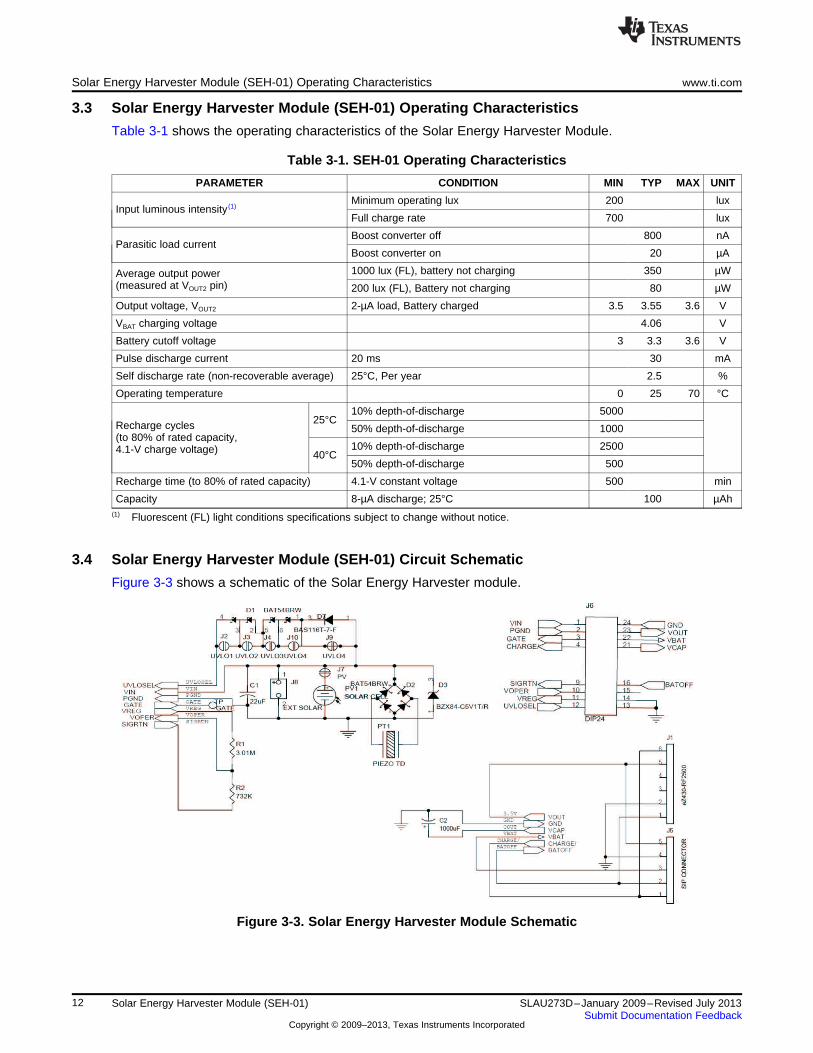
3.3 Solar Energy Harvester Module (SEH-01) Operating Characteristics
Table 3-1 shows the operating characteristics of the Solar Energy Harvester Module.
Table 3-1. SEH-01 Operating Characteristics
PARAMETER CONDITION MIN TYP MAX UNIT
Minimum operating lux 200 luxInput luminous intensity (1)
Full charge rate 700 lux
Boost converter off 800 nAParasitic load current
Boost converter on 20 µA
1000 lux (FL), battery not charging 350 µWAverage output power(measured at VOUT2 pin) 200 lux (FL), Battery not charging 80 µW
Output voltage, VOUT2 2-µA load, Battery charged 3.5 3.55 3.6 V
VBAT charging voltage 4.06 V
Battery cutoff voltage 3 3.3 3.6 V
Pulse discharge current 20 ms 30 mA
Self discharge rate (non-recoverable average) 25°C, Per year 2.5 %
Operating temperature 0 25 70 °C
10% depth-of-discharge 500025°CRecharge cycles 50% depth-of-discharge 1000
(to 80% of rated capacity,10% depth-of-discharge 25004.1-V charge voltage) 40°C50% depth-of-discharge 500
Recharge time (to 80% of rated capacity) 4.1-V constant voltage 500 min
Capacity 8-µA discharge; 25°C 100 µAh(1) Fluorescent (FL) light conditions specifications subject to change without notice.
3.4 Solar Energy Harvester Module (SEH-01) Circuit Schematic
Figure 3-3 shows a schematic of the Solar Energy Harvester module.
Figure 3-3. Solar Energy Harvester Module Schematic
12 Solar Energy Harvester Module (SEH-01) SLAU273D–January 2009–Revised July 2013Submit Documentation Feedback
Copyright © 2009–2013, Texas Instruments Incorporated

www.ti.com Pulse Discharge Current for a Wireless End Device
3.5 Pulse Discharge Current for a Wireless End Device
High current pulses place special demands on batteries. Repeated delivery of pulse currents exceedingthe recommended load current of a given chemistry diminishes the useful life of the cell. The effects canbe severe, depending on the amplitude of the current and the particular cell chemistry and construction.Pulse currents of tens of milliamperes are common in wireless sensor systems during transmit and receivemodes. Moreover, the internal impedance of the cell often results in an internal voltage drop thatprecludes the cell from delivering the pulse current at the voltage necessary to operate the external circuit.
One method of mitigating such effects is to place a low equivalent series resistance (ESR) capacitoracross the battery. The battery charges the capacitor between discharge pulses, and the capacitordelivers the pulse current to the load. Specifying the capacitance for a given battery in an application is astraightforward procedure once a few key parameters are known. The key parameters are:
• Battery impedance (at temperature and state-of-charge)
• Battery voltage (as a function of state-of-charge)
• Operating temperatures
• Pulse current amplitude
• Pulse current duration
• Allowable voltage drop during pulse discharge
Two equations are used to calculate two unknown parameters:
• The output capacitance needed to deliver the specified pulse current of a known duration
• The latency time that must be imposed between pulses to allow the capacitor to be recharged by thebattery
Both formulas assume that the capacitor ESR is sufficiently low to result in negligible internal voltage dropwhile delivering the specified pulse current; consequently, only the battery resistance is considered in theformula used to compute capacitor charging time, and only the load resistance is considered whencomputing the capacitance needed to deliver the discharge current.
The first step in creating a battery-capacitor couple for pulse-current applications is to size the capacitanceusing the following formula:
Discharge formula: C = t / R × [–ln (Vmin / Vmax)]
Where:C = output capacitance in parallel with batteryt = pulse durationR = load resistance = VOUT(average) / Ipulse
Vmin and Vmax are determined by the combination of the battery voltage at a given state-of-charge and theoperating voltage requirement of the external circuit.
Once the capacitance has been determined, the capacitor charging time can be calculated using thefollowing formula:
Charge formula: t = R × C × [–ln (1 – Vmin / Vmax)]
Where:t = capacitor charging time from Vmin to Vmax
R = battery resistanceC = output capacitance in parallel with battery
Again, Vmin and Vmax are functions of the battery voltage and the circuit operating specifications. Batteryresistance varies according to temperature and state-of-charge as described above. Worst-caseconditions are often applied to the calculations to ensure proper system operation over temperatureextremes, battery condition, capacitance tolerance, etc.
13SLAU273D–January 2009–Revised July 2013 Solar Energy Harvester Module (SEH-01)Submit Documentation Feedback
Copyright © 2009–2013, Texas Instruments Incorporated

Chapter 4SLAU273D–January 2009–Revised July 2013
eZ430-RF2500-SEH Sensor Monitor
The eZ430-RF2500-SEH Sensor Monitor is a full demonstration application that includes both thefirmware for the MSP430 that takes into consideration the constraints of running in an energy harvestingenvironment as well as a PC application that can display all connected wireless nodes and the data thatthey are reporting. Both the MSP430 firmware and the PC application (both binary and full source) areincluded in SLAC219.
4.1 MSP430 Firmware
The eZ430-RF2500-SEH Sensor Monitor firmware is preloaded on the MSP430 devices and consists of awireless temperature sensor network and may be reprogrammed at any time. The network consists of anAccess Point that measures its own temperature and also receives data from End Devices. End Devicesmeasure their own temperature periodically and then enter low-power mode to reduce energyconsumption. The Access Point receives the information and transmits it to the PC through USB.SimpliciTI™ is the RF network protocol used to establish the network. For more information on SimpliciTI,visit www.ti.com/simpliciti.
4.1.1 Downloading Firmware to the MSP430
The firmware comes preloaded onto the MSP430 devices; however, it can be restored with the followingsteps. The source code will be installed on the PC with the setup program included in SLAC219.
1. Open Code Composer Studio.
2. Open any available Workspace.
3. Import the project to the Workspace.
(a) Click Project > Open Existing Project > Browse.
(b) Navigate to the source code location. The default location isC:\Texas Instruments\eZ430-RF2500-SEH_Sensor_Monitor-v2.0\CCS_Source.
(c) Ensure "SEH Sensor Monitor" is selected under Projects.
(d) Click Finish.
4. Connect one of the eZ430-RF2500T target boards to the eZ430 Emulator and plug it into a USB porton the computer.
5. Right-click the project name "SEH Sensor Monitor" in the Project Explorer panel and click BuildConfigurations > Set Active > End Device - Debug.
6. Click Project > Clean...
7. Click Run > Debug Active Project.
8. Click the Terminate button (red square in the top left 'Debug' view) to terminate the debugging session.
9. Remove the eZ430-RF2500T target board from the emulator. It has now been programmed as the EndDevice.
10. Connect the second eZ430-RF2500T target board to the eZ430 Emulator and plug it into a USB porton the computer.
11. If not already in the CCS Edit perspective, return to it by clicking the CCS Edit button at the top rightcorner of the screen. Click the >> arrows if the button has moved off-screen.
12. Right-click the "SEH Sensor Monitor" project name in the Project Explorer panel and click BuildConfigurations > Set Active > Access Point - Debug.
13. Click Project > Clean...
14 eZ430-RF2500-SEH Sensor Monitor SLAU273D–January 2009–Revised July 2013Submit Documentation Feedback
Copyright © 2009–2013, Texas Instruments Incorporated

www.ti.com PC Sensor Monitor Application
14. Click Run > Debug Active Project and click the green Run arrow button.
15. Connect the first eZ430-RF2500T (End Device) target board to the battery pack or the Solar EnergyHarvesting board.
16. Open the eZ430-RF2500 Sensor Monitor PC program installed on the PC to watch the network formor receive data from the wireless node.
4.2 PC Sensor Monitor Application
The Sensor Monitor PC application is a graphical representation of the star network and displays thesampled data from each wireless device. The center node is the Access Point and the attached nodes arethe End Devices, which display their temperature, voltage, and their transmission frequency. The physicaldistance of the End Device from the Access Point is simulated on-screen by measuring the signal strength(RSSI) of the received signal. The number of End Devices can be expanded by adding more wirelessnodes to the network as shown in Figure 4-1.
Figure 4-1. eZ430-RF2500-SEH Sensor Monitor
4.2.1 Energy Awareness
Because the End Devices are 'Energy Aware', they dynamically switch power sources from the solar cellto the EnerChip if sufficient ambient light is not available to run the system. The node's color on the PCSensor Monitor window also displays its current power source. The node is yellow when powered from thesolar panel or the traditional battery back and is blue when running from the EnerChip.
4.2.2 Remaining Transmissions
When running from the EnerChip, the application also display the number of transmissions left before thestored energy is depleted. On average, ~400 transmissions are possible before the system needs to berecharged.
4.2.3 Menu Bar
Figure 4-2 describes the eZ430-RF2500-SEH Sensor Monitor menu bar.
15SLAU273D–January 2009–Revised July 2013 eZ430-RF2500-SEH Sensor MonitorSubmit Documentation Feedback
Copyright © 2009–2013, Texas Instruments Incorporated

Play
Pause
StopCOM Port Selection
Console
Graph node data
User's guide
Configurations
About
PC Sensor Monitor Application www.ti.com
Figure 4-2. Menu Bar
4.2.3.1 Action Toolbar: Play, Pause, Stop
By default, the Sensor Monitor scans all available COM ports until it finds an MSP430 Application UARTand begins receiving data. The Play, Pause, and Stop controls are available to control the connection withthe COM port.
Play — Opens the MSP430 application UART COM port and resumes receiving data.
Pause — Closes the COM port, which stops the application from receiving data.
Stop — Closes the COM port, which stops the application from receiving data and clears the nodes fromthe window.
4.2.3.2 Console Window
The console window (see Figure 4-3) is used to view a real-time output of all node data in text format.Individual nodes, including the access point, can be removed from the console if necessary. This can beuseful when looking for a specific node's information. It is also possible to save the data in the console toa text file for further analysis and processing.
Figure 4-3. Console Window
4.2.3.3 Graph Window
Temperature data and RF signal strength (RSSI) for all nodes can be plotted in a graph (see Figure 4-4).The signal strength is displayed as a percentage. The last 60 transmissions are stored and displayed.Only 24 hours worth of data can be displayed.
16 eZ430-RF2500-SEH Sensor Monitor SLAU273D–January 2009–Revised July 2013Submit Documentation Feedback
Copyright © 2009–2013, Texas Instruments Incorporated

www.ti.com PC Sensor Monitor Application
Figure 4-4. Real-Time Node Data from the Graph Window
4.2.3.4 COM Port Selection
By default, the application selects and opens the first available MSP430 Application UART and refreshesthe drop down whenever a new COM port is available. This means it is rarely necessary to use the COMport selection list unless multiple MSP430 Applications UARTs are available on the PC.
4.2.3.5 Configurations
Settings for the Sensor Monitor application can be changed in the configurations window. The defaulttemperature unit can be modified as well as the time required before a node is removed if a packet hasnot been received in a while.
Figure 4-5. Configurations Window
17SLAU273D–January 2009–Revised July 2013 eZ430-RF2500-SEH Sensor MonitorSubmit Documentation Feedback
Copyright © 2009–2013, Texas Instruments Incorporated

PC Sensor Monitor Application www.ti.com
4.2.4 PC Sensor Monitor Application Source Code
The eZ430-RF2500-SEH Sensor Monitor application is open source and is licensed under GNU GeneralPublic License v2. The source code is included in SLAC219. It was developed using the open source Qtcross-platform applications framework (QWT) and compiled using Microsoft Visual C++ 2008 ExpressEdition, which are freely available. For detailed instructions on how to setup the environment to edit theproject, see the README.txt in the source code directory.
18 eZ430-RF2500-SEH Sensor Monitor SLAU273D–January 2009–Revised July 2013Submit Documentation Feedback
Copyright © 2009–2013, Texas Instruments Incorporated

Appendix ASLAU273D–January 2009–Revised July 2013
Frequently Asked Questions
A.1 FAQs1. My End Device doesn't join the network or it takes several tries to successfully join the
network?The startup and network linking process is a very demanding from a power-consumption perspective,because both the MSP430 and the CC2500 turn on in a full active mode at startup, which is a drain onpower when working with such a limited power budget. Also, linking to an RF network requiresscanning the area and exchanging packets between the ED and AP with the potential for re-transmissions. High-current pulses, such as RF communication, are sourced from the 1000-µFcapacitor, and if all the energy is drained in a short period of time, it must be recharged prior byholding the solar cell under a bright light prior to another attempt to join the network.
2. I've left the Solar Energy Harvesting Module under a bright light for three days, but it stilldoesn't work in the dark?The shunt on J8 must be removed to charge the EnerChip from the solar cell. With J8 in place, thebattery is isolated to prevent potential damage caused by it draining while in transport or storage.
3. Why does the Solar Energy Harvester Module use thin film rechargeable batteries instead of arechargeable AA, super cap, or other exotic storage solution?Energy harvesting applications can also run from any other storage element. Thin film batteries havethe advantage of being easily recharged, have a small profile and, most importantly, have a negligibleself-discharge. Self discharge is the property of batteries or capacitors to lose charge over time;however, thin film batteries lose only a small percentage of their charge over a long period of time.
4. Why is the battery pack included if the eZ430-RF2500T is intended to run from the Solar EnergyHarvester?The battery pack is may be useful when trying to debug an application that has not been optimallytuned to run in an efficient energy harvesting environment.
5. The reported temperature is incorrect, how can I calibrate the sensor?A temperature offset is stored in Flash, which is calibrated at production. If the offset is erased or isincorrect, it can be changed to an appropriate level for your application.
6. Where can I get the part number for the solar panel or the rest of build of material (BOM) for theSolar Energy Harvesting module?Please send all questions on the Solar Energy Harvesting Module to Cymbet (www.cymbet.com)
7. Where do I find more information on the eZ430-RF2500 wireless development tool?The eZ430-RF2500 Development Tool User's Guide (SLAU227)
8. When I try to compile the source code with IAR Kickstart, I get the following error:Fatal Error[e89]: Too much object code produced (more than 0x1000 bytes) for this packageIAR KickStart currently has a 4KB code size limitation, and the project being compiled is larger than4KB. (0x1000 = 4096). To compile, a full license of IAR is required. A 30-day evaluation version of IARis available from http://supp.iar.com/Download/SW/?item=EW430-EVAL.
19SLAU273D–January 2009–Revised July 2013 Frequently Asked QuestionsSubmit Documentation Feedback
Copyright © 2009–2013, Texas Instruments Incorporated
FAQs www.ti.com
9. Why is the solar panel on the energy harvesting board so large when my TI-36X works finewith a tiny solar panel?
The current required to run a calculator and LCD is relatively small. Running a wireless sensornetwork, however, consumes approximately 10 mA to 25 mA when trying to simultaneously samplesensors and transmit data wirelessly. This current might be 100 to 1000 times more than a calculatorapplication. A larger solar panel allows collection of more solar energy to keep up with the real-timedemands of a wireless system with a high duty cycle. The design could be optimized with a smallersolar cell, but the frequency of RF transmissions would have to be reduced.
20 Frequently Asked Questions SLAU273D–January 2009–Revised July 2013Submit Documentation Feedback
Copyright © 2009–2013, Texas Instruments Incorporated

EVALUATION BOARD/KIT/MODULE (EVM) ADDITIONAL TERMS
Texas Instruments (TI) provides the enclosed Evaluation Board/Kit/Module (EVM) under the following conditions:
The user assumes all responsibility and liability for proper and safe handling of the goods. Further, the user indemnifies TI from all claimsarising from the handling or use of the goods.
Should this evaluation board/kit not meet the specifications indicated in the User’s Guide, the board/kit may be returned within 30 days fromthe date of delivery for a full refund. THE FOREGOING LIMITED WARRANTY IS THE EXCLUSIVE WARRANTY MADE BY SELLER TOBUYER AND IS IN LIEU OF ALL OTHER WARRANTIES, EXPRESSED, IMPLIED, OR STATUTORY, INCLUDING ANY WARRANTY OFMERCHANTABILITY OR FITNESS FOR ANY PARTICULAR PURPOSE. EXCEPT TO THE EXTENT OF THE INDEMNITY SET FORTHABOVE, NEITHER PARTY SHALL BE LIABLE TO THE OTHER FOR ANY INDIRECT, SPECIAL, INCIDENTAL, OR CONSEQUENTIALDAMAGES.
Please read the User's Guide and, specifically, the Warnings and Restrictions notice in the User's Guide prior to handling the product. Thisnotice contains important safety information about temperatures and voltages. For additional information on TI's environmental and/or safetyprograms, please visit www.ti.com/esh or contact TI.
No license is granted under any patent right or other intellectual property right of TI covering or relating to any machine, process, orcombination in which such TI products or services might be or are used. TI currently deals with a variety of customers for products, andtherefore our arrangement with the user is not exclusive. TI assumes no liability for applications assistance, customer product design,software performance, or infringement of patents or services described herein.
REGULATORY COMPLIANCE INFORMATION
As noted in the EVM User’s Guide and/or EVM itself, this EVM and/or accompanying hardware may or may not be subject to the FederalCommunications Commission (FCC) and Industry Canada (IC) rules.
For EVMs not subject to the above rules, this evaluation board/kit/module is intended for use for ENGINEERING DEVELOPMENT,DEMONSTRATION OR EVALUATION PURPOSES ONLY and is not considered by TI to be a finished end product fit for general consumeruse. It generates, uses, and can radiate radio frequency energy and has not been tested for compliance with the limits of computingdevices pursuant to part 15 of FCC or ICES-003 rules, which are designed to provide reasonable protection against radio frequencyinterference. Operation of the equipment may cause interference with radio communications, in which case the user at his own expense willbe required to take whatever measures may be required to correct this interference.
General Statement for EVMs including a radio
User Power/Frequency Use Obligations: This radio is intended for development/professional use only in legally allocated frequency andpower limits. Any use of radio frequencies and/or power availability of this EVM and its development application(s) must comply with locallaws governing radio spectrum allocation and power limits for this evaluation module. It is the user’s sole responsibility to only operate thisradio in legally acceptable frequency space and within legally mandated power limitations. Any exceptions to this are strictly prohibited andunauthorized by Texas Instruments unless user has obtained appropriate experimental/development licenses from local regulatoryauthorities, which is responsibility of user including its acceptable authorization.
For EVMs annotated as FCC – FEDERAL COMMUNICATIONS COMMISSION Part 15 Compliant
Caution
This device complies with part 15 of the FCC Rules. Operation is subject to the following two conditions: (1) This device may not causeharmful interference, and (2) this device must accept any interference received, including interference that may cause undesired operation.
Changes or modifications not expressly approved by the party responsible for compliance could void the user's authority to operate theequipment.
FCC Interference Statement for Class A EVM devices
This equipment has been tested and found to comply with the limits for a Class A digital device, pursuant to part 15 of the FCC Rules.These limits are designed to provide reasonable protection against harmful interference when the equipment is operated in a commercialenvironment. This equipment generates, uses, and can radiate radio frequency energy and, if not installed and used in accordance with theinstruction manual, may cause harmful interference to radio communications. Operation of this equipment in a residential area is likely tocause harmful interference in which case the user will be required to correct the interference at his own expense.

FCC Interference Statement for Class B EVM devices
This equipment has been tested and found to comply with the limits for a Class B digital device, pursuant to part 15 of the FCC Rules.These limits are designed to provide reasonable protection against harmful interference in a residential installation. This equipmentgenerates, uses and can radiate radio frequency energy and, if not installed and used in accordance with the instructions, may causeharmful interference to radio communications. However, there is no guarantee that interference will not occur in a particular installation. Ifthis equipment does cause harmful interference to radio or television reception, which can be determined by turning the equipment off andon, the user is encouraged to try to correct the interference by one or more of the following measures:
• Reorient or relocate the receiving antenna.• Increase the separation between the equipment and receiver.• Connect the equipment into an outlet on a circuit different from that to which the receiver is connected.• Consult the dealer or an experienced radio/TV technician for help.
For EVMs annotated as IC – INDUSTRY CANADA Compliant
This Class A or B digital apparatus complies with Canadian ICES-003.
Changes or modifications not expressly approved by the party responsible for compliance could void the user’s authority to operate theequipment.
Concerning EVMs including radio transmitters
This device complies with Industry Canada licence-exempt RSS standard(s). Operation is subject to the following two conditions: (1) thisdevice may not cause interference, and (2) this device must accept any interference, including interference that may cause undesiredoperation of the device.
Concerning EVMs including detachable antennas
Under Industry Canada regulations, this radio transmitter may only operate using an antenna of a type and maximum (or lesser) gainapproved for the transmitter by Industry Canada. To reduce potential radio interference to other users, the antenna type and its gain shouldbe so chosen that the equivalent isotropically radiated power (e.i.r.p.) is not more than that necessary for successful communication.
This radio transmitter has been approved by Industry Canada to operate with the antenna types listed in the user guide with the maximumpermissible gain and required antenna impedance for each antenna type indicated. Antenna types not included in this list, having a gaingreater than the maximum gain indicated for that type, are strictly prohibited for use with this device.
Cet appareil numérique de la classe A ou B est conforme à la norme NMB-003 du Canada.
Les changements ou les modifications pas expressément approuvés par la partie responsable de la conformité ont pu vider l’autorité del'utilisateur pour actionner l'équipement.
Concernant les EVMs avec appareils radio
Le présent appareil est conforme aux CNR d'Industrie Canada applicables aux appareils radio exempts de licence. L'exploitation estautorisée aux deux conditions suivantes : (1) l'appareil ne doit pas produire de brouillage, et (2) l'utilisateur de l'appareil doit accepter toutbrouillage radioélectrique subi, même si le brouillage est susceptible d'en compromettre le fonctionnement.
Concernant les EVMs avec antennes détachables
Conformément à la réglementation d'Industrie Canada, le présent émetteur radio peut fonctionner avec une antenne d'un type et d'un gainmaximal (ou inférieur) approuvé pour l'émetteur par Industrie Canada. Dans le but de réduire les risques de brouillage radioélectrique àl'intention des autres utilisateurs, il faut choisir le type d'antenne et son gain de sorte que la puissance isotrope rayonnée équivalente(p.i.r.e.) ne dépasse pas l'intensité nécessaire à l'établissement d'une communication satisfaisante.
Le présent émetteur radio a été approuvé par Industrie Canada pour fonctionner avec les types d'antenne énumérés dans le manueld’usage et ayant un gain admissible maximal et l'impédance requise pour chaque type d'antenne. Les types d'antenne non inclus danscette liste, ou dont le gain est supérieur au gain maximal indiqué, sont strictement interdits pour l'exploitation de l'émetteur.
SPACER
SPACER
SPACER
SPACER
SPACER
SPACER
SPACER
SPACER
【【Important Notice for Users of EVMs for RF Products in Japan】】This development kit is NOT certified as Confirming to Technical Regulations of Radio Law of Japan
If you use this product in Japan, you are required by Radio Law of Japan to follow the instructions below with respect to this product:
1. Use this product in a shielded room or any other test facility as defined in the notification #173 issued by Ministry of Internal Affairs andCommunications on March 28, 2006, based on Sub-section 1.1 of Article 6 of the Ministry’s Rule for Enforcement of Radio Law ofJapan,
2. Use this product only after you obtained the license of Test Radio Station as provided in Radio Law of Japan with respect to thisproduct, or
3. Use of this product only after you obtained the Technical Regulations Conformity Certification as provided in Radio Law of Japan withrespect to this product. Also, please do not transfer this product, unless you give the same notice above to the transferee. Please notethat if you could not follow the instructions above, you will be subject to penalties of Radio Law of Japan.
Texas Instruments Japan Limited(address) 24-1, Nishi-Shinjuku 6 chome, Shinjuku-ku, Tokyo, Japan
http://www.tij.co.jp
【無線電波を送信する製品の開発キットをお使いになる際の注意事項】
本開発キットは技術基準適合証明を受けておりません。
本製品のご使用に際しては、電波法遵守のため、以下のいずれかの措置を取っていただく必要がありますのでご注意ください。1. 電波法施行規則第6条第1項第1号に基づく平成18年3月28日総務省告示第173号で定められた電波暗室等の試験設備でご使用いただく。2. 実験局の免許を取得後ご使用いただく。3. 技術基準適合証明を取得後ご使用いただく。
なお、本製品は、上記の「ご使用にあたっての注意」を譲渡先、移転先に通知しない限り、譲渡、移転できないものとします。
上記を遵守頂けない場合は、電波法の罰則が適用される可能性があることをご留意ください。
日本テキサス・インスツルメンツ株式会社東京都新宿区西新宿6丁目24番1号西新宿三井ビルhttp://www.tij.co.jp
SPACER
SPACER
SPACER
SPACER
SPACER
SPACER
SPACER
SPACER
SPACER
SPACER
SPACER
SPACER
SPACER
SPACER
SPACER
SPACER
SPACER

EVALUATION BOARD/KIT/MODULE (EVM)WARNINGS, RESTRICTIONS AND DISCLAIMERS
For Feasibility Evaluation Only, in Laboratory/Development Environments. Unless otherwise indicated, this EVM is not a finishedelectrical equipment and not intended for consumer use. It is intended solely for use for preliminary feasibility evaluation inlaboratory/development environments by technically qualified electronics experts who are familiar with the dangers and application risksassociated with handling electrical mechanical components, systems and subsystems. It should not be used as all or part of a finished endproduct.
Your Sole Responsibility and Risk. You acknowledge, represent and agree that:
1. You have unique knowledge concerning Federal, State and local regulatory requirements (including but not limited to Food and DrugAdministration regulations, if applicable) which relate to your products and which relate to your use (and/or that of your employees,affiliates, contractors or designees) of the EVM for evaluation, testing and other purposes.
2. You have full and exclusive responsibility to assure the safety and compliance of your products with all such laws and other applicableregulatory requirements, and also to assure the safety of any activities to be conducted by you and/or your employees, affiliates,contractors or designees, using the EVM. Further, you are responsible to assure that any interfaces (electronic and/or mechanical)between the EVM and any human body are designed with suitable isolation and means to safely limit accessible leakage currents tominimize the risk of electrical shock hazard.
3. Since the EVM is not a completed product, it may not meet all applicable regulatory and safety compliance standards (such as UL,CSA, VDE, CE, RoHS and WEEE) which may normally be associated with similar items. You assume full responsibility to determineand/or assure compliance with any such standards and related certifications as may be applicable. You will employ reasonablesafeguards to ensure that your use of the EVM will not result in any property damage, injury or death, even if the EVM should fail toperform as described or expected.
4. You will take care of proper disposal and recycling of the EVM’s electronic components and packing materials.
Certain Instructions. It is important to operate this EVM within TI’s recommended specifications and environmental considerations per theuser guidelines. Exceeding the specified EVM ratings (including but not limited to input and output voltage, current, power, andenvironmental ranges) may cause property damage, personal injury or death. If there are questions concerning these ratings please contacta TI field representative prior to connecting interface electronics including input power and intended loads. Any loads applied outside of thespecified output range may result in unintended and/or inaccurate operation and/or possible permanent damage to the EVM and/orinterface electronics. Please consult the EVM User's Guide prior to connecting any load to the EVM output. If there is uncertainty as to theload specification, please contact a TI field representative. During normal operation, some circuit components may have case temperaturesgreater than 60°C as long as the input and output are maintained at a normal ambient operating temperature. These components includebut are not limited to linear regulators, switching transistors, pass transistors, and current sense resistors which can be identified using theEVM schematic located in the EVM User's Guide. When placing measurement probes near these devices during normal operation, pleasebe aware that these devices may be very warm to the touch. As with all electronic evaluation tools, only qualified personnel knowledgeablein electronic measurement and diagnostics normally found in development environments should use these EVMs.
Agreement to Defend, Indemnify and Hold Harmless. You agree to defend, indemnify and hold TI, its licensors and their representativesharmless from and against any and all claims, damages, losses, expenses, costs and liabilities (collectively, "Claims") arising out of or inconnection with any use of the EVM that is not in accordance with the terms of the agreement. This obligation shall apply whether Claimsarise under law of tort or contract or any other legal theory, and even if the EVM fails to perform as described or expected.
Safety-Critical or Life-Critical Applications. If you intend to evaluate the components for possible use in safety critical applications (suchas life support) where a failure of the TI product would reasonably be expected to cause severe personal injury or death, such as deviceswhich are classified as FDA Class III or similar classification, then you must specifically notify TI of such intent and enter into a separateAssurance and Indemnity Agreement.
Mailing Address: Texas Instruments, Post Office Box 655303, Dallas, Texas 75265Copyright © 2013, Texas Instruments Incorporated

IMPORTANT NOTICE
Texas Instruments Incorporated and its subsidiaries (TI) reserve the right to make corrections, enhancements, improvements and otherchanges to its semiconductor products and services per JESD46, latest issue, and to discontinue any product or service per JESD48, latestissue. Buyers should obtain the latest relevant information before placing orders and should verify that such information is current andcomplete. All semiconductor products (also referred to herein as “components”) are sold subject to TI’s terms and conditions of salesupplied at the time of order acknowledgment.
TI warrants performance of its components to the specifications applicable at the time of sale, in accordance with the warranty in TI’s termsand conditions of sale of semiconductor products. Testing and other quality control techniques are used to the extent TI deems necessaryto support this warranty. Except where mandated by applicable law, testing of all parameters of each component is not necessarilyperformed.
TI assumes no liability for applications assistance or the design of Buyers’ products. Buyers are responsible for their products andapplications using TI components. To minimize the risks associated with Buyers’ products and applications, Buyers should provideadequate design and operating safeguards.
TI does not warrant or represent that any license, either express or implied, is granted under any patent right, copyright, mask work right, orother intellectual property right relating to any combination, machine, or process in which TI components or services are used. Informationpublished by TI regarding third-party products or services does not constitute a license to use such products or services or a warranty orendorsement thereof. Use of such information may require a license from a third party under the patents or other intellectual property of thethird party, or a license from TI under the patents or other intellectual property of TI.
Reproduction of significant portions of TI information in TI data books or data sheets is permissible only if reproduction is without alterationand is accompanied by all associated warranties, conditions, limitations, and notices. TI is not responsible or liable for such altereddocumentation. Information of third parties may be subject to additional restrictions.
Resale of TI components or services with statements different from or beyond the parameters stated by TI for that component or servicevoids all express and any implied warranties for the associated TI component or service and is an unfair and deceptive business practice.TI is not responsible or liable for any such statements.
Buyer acknowledges and agrees that it is solely responsible for compliance with all legal, regulatory and safety-related requirementsconcerning its products, and any use of TI components in its applications, notwithstanding any applications-related information or supportthat may be provided by TI. Buyer represents and agrees that it has all the necessary expertise to create and implement safeguards whichanticipate dangerous consequences of failures, monitor failures and their consequences, lessen the likelihood of failures that might causeharm and take appropriate remedial actions. Buyer will fully indemnify TI and its representatives against any damages arising out of the useof any TI components in safety-critical applications.
In some cases, TI components may be promoted specifically to facilitate safety-related applications. With such components, TI’s goal is tohelp enable customers to design and create their own end-product solutions that meet applicable functional safety standards andrequirements. Nonetheless, such components are subject to these terms.
No TI components are authorized for use in FDA Class III (or similar life-critical medical equipment) unless authorized officers of the partieshave executed a special agreement specifically governing such use.
Only those TI components which TI has specifically designated as military grade or “enhanced plastic” are designed and intended for use inmilitary/aerospace applications or environments. Buyer acknowledges and agrees that any military or aerospace use of TI componentswhich have not been so designated is solely at the Buyer's risk, and that Buyer is solely responsible for compliance with all legal andregulatory requirements in connection with such use.
TI has specifically designated certain components as meeting ISO/TS16949 requirements, mainly for automotive use. In any case of use ofnon-designated products, TI will not be responsible for any failure to meet ISO/TS16949.
Products Applications
Audio www.ti.com/audio Automotive and Transportation www.ti.com/automotive
Amplifiers amplifier.ti.com Communications and Telecom www.ti.com/communications
Data Converters dataconverter.ti.com Computers and Peripherals www.ti.com/computers
DLP® Products www.dlp.com Consumer Electronics www.ti.com/consumer-apps
DSP dsp.ti.com Energy and Lighting www.ti.com/energy
Clocks and Timers www.ti.com/clocks Industrial www.ti.com/industrial
Interface interface.ti.com Medical www.ti.com/medical
Logic logic.ti.com Security www.ti.com/security
Power Mgmt power.ti.com Space, Avionics and Defense www.ti.com/space-avionics-defense
Microcontrollers microcontroller.ti.com Video and Imaging www.ti.com/video
RFID www.ti-rfid.com
OMAP Applications Processors www.ti.com/omap TI E2E Community e2e.ti.com
Wireless Connectivity www.ti.com/wirelessconnectivity
Mailing Address: Texas Instruments, Post Office Box 655303, Dallas, Texas 75265Copyright © 2013, Texas Instruments Incorporated

![Operating the A/D Converter of the MSP430 Microcontroller€¦ · Section 4 supports you to start TI’s eZ430-RF2500 kit [4] used for this lab exercises. Section 5 offers some information](https://static.documents.pub/doc/80x56/60ba51e9bf76c53b1d3def8e/operating-the-ad-converter-of-the-msp430-microcontroller-section-4-supports-you.jpg)


