102
eZ430-Chronos™ Development Tool User's Guide Literature Number: SLAU292C November 2009 – Revised December 2010
eZ430-Chronos™ Development Tool
User's Guide
Literature Number: SLAU292C
November 2009–Revised December 2010
Contents
Preface ....................................................................................................................................... 7
1 eZ430-Chronos™ Overview .................................................................................................. 81.1 Overview ..................................................................................................................... 81.2 Kit Contents .................................................................................................................. 9
2 Getting Started .................................................................................................................. 102.1 Using the eZ430-Chronos Watch Stand Alone ........................................................................ 10
2.1.1 Setting the Time .................................................................................................. 102.1.2 Setting the Date .................................................................................................. 112.1.3 Feature Overview and Menu Structure ........................................................................ 11
2.2 Install Demo Application, Drivers and Firmware ...................................................................... 122.2.1 Windows® Installation ........................................................................................... 122.2.2 Linux® Installation ................................................................................................ 12
2.3 Using the eZ430-Chronos Watch With a PC .......................................................................... 132.3.1 Transmission of Acceleration Data and Button Pushes ..................................................... 13
3 eZ430-Chronos Software .................................................................................................... 163.1 Overview .................................................................................................................... 163.2 eZ430-Chronos Sports Watch Software ................................................................................ 16
3.2.1 Detailed Feature Overview - Modes Using the Top LCD Line ............................................. 183.2.2 Detailed Feature Overview - Modes Using the Bottom LCD Line .......................................... 21
3.3 eZ430-Chronos Control Center PC Software .......................................................................... 243.3.1 SimpliciTI™ Acc/PPT Tab (Mouse and PowerPoint Control) ............................................... 253.3.2 Key Configuration Tab ........................................................................................... 283.3.3 SimpliciTI™ Sync ................................................................................................. 293.3.4 BlueRobin™ Heart Rate Simulator ............................................................................. 303.3.5 Wireless Update .................................................................................................. 31
3.4 eZ430-Chronos Watch Data Logger .................................................................................... 333.4.1 Detailed Feature Overview ...................................................................................... 34
3.5 Data Logger PC Software ................................................................................................ 343.5.1 SimpliciTI Data Logger ........................................................................................... 353.5.2 Wireless Update .................................................................................................. 37
3.6 eZ430-Chronos Software Projects ...................................................................................... 383.6.1 IDE Installation .................................................................................................... 383.6.2 eZ430-Chronos Watch Software Flow ......................................................................... 393.6.3 eZ430-Chronos Wireless Update Feature .................................................................... 413.6.4 eZ430-Chronos Firmware ....................................................................................... 463.6.5 eZ430-Chronos GUI Sources ................................................................................... 47
4 eZ430-Chronos Hardware ................................................................................................... 534.1 Programming/Reprogramming the eZ430-Chronos Watch: Disassembly and Assembly of the Housing ..... 53
4.1.1 Disassembly of eZ430-Chronos Watch ........................................................................ 534.1.2 Assembly of eZ430-Chronos Watch ........................................................................... 55
4.2 Functional Description of the eZ430-Chronos Watch ................................................................. 574.3 Functional Description of the eZ430-Chronos RF Access Point .................................................... 594.4 Functional Description of the eZ430-Chronos Debug Interface ..................................................... 60
4.4.1 MSP430 Application UART ..................................................................................... 60
2 Contents SLAU292C–November 2009–Revised December 2010Submit Documentation Feedback
© 2009–2010, Texas Instruments Incorporated
www.ti.com
4.5 Schematics, Layout, BOM, and LCD ................................................................................... 614.5.1 eZ430-Chronos-433 Watches ................................................................................... 614.5.2 eZ430-Chronos-868 and -915 Watches ....................................................................... 69
4.6 Access Point Schematics, Layout and BOM ........................................................................... 794.6.1 eZ430-Chronos-433 RF Access Point ......................................................................... 794.6.2 eZ430-Chronos-868 and 915 RF Access Point .............................................................. 844.6.3 Debugging Interface Schematics and Layout ................................................................. 90
A Frequently Asked Questions ............................................................................................... 93A.1 FAQs ........................................................................................................................ 93
B Detailed Hardware Driver Installation Guide .......................................................................... 96B.1 eZ430-Chronos RF Access Point ....................................................................................... 96B.2 eZ430-RF Debug Interface ............................................................................................. 100
3SLAU292C–November 2009–Revised December 2010 ContentsSubmit Documentation Feedback
© 2009–2010, Texas Instruments Incorporated
www.ti.com
List of Figures
1-1. eZ430-Chronos.............................................................................................................. 8
2-1. eZ430-Chronos Watch Push Buttons ................................................................................... 10
2-2. Overview eZ430-Chronos LCD .......................................................................................... 10
2-3. eZ430-Chronos Feature Overview and Menu Structure ............................................................. 11
2-4. eZ430-Chronos Control Center .......................................................................................... 13
2-5. eZ430-Chronos Control Center With Acceleration Data ............................................................. 14
3-1. eZ430-Chronos Feature Overview and Menu Structure ............................................................. 17
3-2. eZ430-Chronos Control Center .......................................................................................... 25
3-3. eZ430-Chronos Control Center With Acceleration Data ............................................................. 26
3-4. eZ430-Chronos Control Center With PPT Control .................................................................... 27
3-5. eZ430-Chronos Control Center Key Configuration ................................................................... 28
3-6. eZ430-Chronos Control Center Sync ................................................................................... 29
3-7. eZ430-Chronos Control Center Heart Rate Simulator................................................................ 30
3-8. eZ430-Chronos Control Center Wireless Update ..................................................................... 32
3-9. eZ430-Chronos Data Logger Feature Overview and Menu Structure.............................................. 33
3-10. eZ430-Chronos Data Logger ............................................................................................ 36
3-11. eZ430-Chronos Control Center Wireless Update ..................................................................... 38
3-12. eZ430-Chronos Software Flowchart .................................................................................... 40
3-13. Flow Chart of Wireless Updater on Access Point ..................................................................... 42
3-14. Flow Chart of Flash Based Wireless Updater on eZ430-Chronos Watch Module ................................ 43
3-15. eZ430-Chronos RF Access Point Connection to CC Debugger .................................................... 44
3-16. SmartRF Flash Programmer ............................................................................................. 45
4-1. Removing Watch Module from Housing................................................................................ 53
4-2. Removing Watch Battery ................................................................................................. 54
4-3. eZ430-Chronos Watch Module Attached to eZ430-RF Debug Interface........................................... 55
4-4. eZ430-Chronos Watch Module Insertion Into Housing ............................................................... 55
4-5. Metal Strips of Watch Housing and Buttons of Housing ............................................................. 56
4-6. Push Metal Strips Inward................................................................................................. 56
4-7. eZ430-Chronos Watch Block Diagram ................................................................................. 57
4-8. eZ430-Chronos Watch Module Front ................................................................................... 57
4-9. eZ430-Chronos Watch Module Back ................................................................................... 58
4-10. eZ430-Chronos RF Access Point ....................................................................................... 59
4-11. eZ430-Chronos RF Access Point Connection to CC Debugger .................................................... 59
4-12. eZ430-Chronos Debug Interface ........................................................................................ 60
4-13. eZ430-Chronos-433 Watch, Schematics ............................................................................... 61
4-14. eZ430-Chronos-433 Watch, PCB Components on Top Layer ...................................................... 62
4-15. eZ430-Chronos-433 Watch, Layout Top Layer (LCD Side) ......................................................... 63
4-16. eZ430-Chronos-433 Watch, Layout Second Layer ................................................................... 64
4-17. eZ430-Chronos-433 Watch, Layout 3rd Layer ........................................................................ 65
4-18. eZ430-Chronos-433, Layout Bottom Layer (Battery Side) ........................................................... 66
4-19. eZ430-Chronos-868 and -915 Watch, Schematics ................................................................... 69
4-20. eZ430-Chronos-868 and -915 Watch, PCB Components on Top Layer ........................................... 70
4-21. eZ430-Chronos-868 and -915 Watch, Layout Top Layer (LCD Side) .............................................. 71
4-22. eZ430-Chronos-868 and -915 Watch, Layout 2nd Layer ............................................................ 72
4-23. eZ430-Chronos-868 and -915 Watch, Layout 3rd Layer ............................................................. 73
4-24. eZ430-Chronos-868 and -915 Watch, Layout Bottom Layer (Battery Side) ....................................... 74
4-25. LCD Segment Map ........................................................................................................ 77
4 List of Figures SLAU292C–November 2009–Revised December 2010Submit Documentation Feedback
© 2009–2010, Texas Instruments Incorporated
www.ti.com
4-26. LCD Pinout ................................................................................................................. 78
4-27. eZ430-Chronos-433 RF Access Point, Schematics .................................................................. 79
4-28. eZ430-Chronos-433 RF Access Point, PCB Components on Top Layer .......................................... 80
4-29. eZ430-Chronos-433 RF Access Point, Layout Top Layer ........................................................... 81
4-30. eZ430-Chronos-433 RF Access Point, Layout Bottom Layer ....................................................... 82
4-31. eZ430-Chronos-868 and -915 RF Access Point, Schematics ....................................................... 84
4-32. eZ430-Chronos-868 and -915 RF Access Point, PCB Components on Top Layer .............................. 85
4-33. eZ430-Chronos-868 and -915 RF Access Point, Layout Top Layer................................................ 86
4-34. eZ430-Chronos-868 and -915 RF Access Point, Layout Bottom Layer ............................................ 87
4-35. USB Debug Interface, Schematic ....................................................................................... 90
4-36. USB Debug Interface, Schematic ....................................................................................... 91
4-37. USB Debug Interface, PCB Components on Top Layer ............................................................. 92
4-38. USB Debug Interface, PCB Components on Bottom Layer ......................................................... 92
4-39. USB Debug Interface, Layout Top Layer............................................................................... 92
4-40. USB Debug Interface, Layout Bottom Layer........................................................................... 92
B-1. Device Driver installation Wizard for the Access Point ............................................................... 96
B-2. Successful Driver Installation for Access Point........................................................................ 97
B-3. Access Point Detection ................................................................................................... 97
B-4. Windows Found New Hardware Wizard................................................................................ 98
B-5. Automatic Driver installation ............................................................................................. 98
B-6. Windows Uncertified Driver Installation Warning...................................................................... 99
B-7. Access Point in Windows Device Manager ............................................................................ 99
B-8. CC1111 Port Settings ................................................................................................... 100
B-9. eZ430-RF Windows Driver Installation ................................................................................ 100
B-10. eZ430-RF in Windows Device Manager as HID and COM Port Devices ........................................ 101
5SLAU292C–November 2009–Revised December 2010 List of FiguresSubmit Documentation Feedback
© 2009–2010, Texas Instruments Incorporated
www.ti.com
List of Tables
4-1. Estimated Battery Life (Sports Watch Software) ...................................................................... 58
4-2. eZ430-Chronos-433 Watch, BOM List.................................................................................. 67
4-3. eZ430-Chronos-868 and -915 Watch, BOM List ...................................................................... 75
4-4. eZ430-Chronos-433 Access Point, BOM List.......................................................................... 83
4-5. eZ430-Chronos-868 Access Point, BOM List.......................................................................... 88
4-6. eZ430-Chronos-915 Access Point, BOM List.......................................................................... 89
6 List of Tables SLAU292C–November 2009–Revised December 2010Submit Documentation Feedback
© 2009–2010, Texas Instruments Incorporated

PrefaceSLAU292C–November 2009–Revised December 2010
Read This First
If You Need Assistance
If you have any feedback or questions, support for the MSP430™ devices and the eZ430-Chronos™software development tool is provided by the Texas Instruments Product Information Center (PIC) (seesupport.ti.com), the TI E2E Forum (http://e2e.ti.com/support/microcontrollers/msp43016-bit_ultra-low_power_mcus/f/166.aspx), and the eZ430-Chronos wiki at www.ti.com/chronoswiki. Additional device-specific information can be found on the MSP430 web site, www.ti.com/msp430.
Related Documentation from Texas Instruments
The primary sources of MSP430 information are the device-specific data sheets and user's guides. Themost up-to-date versions of the user's guide documents available at the time of production have beenprovided on the CD-ROM included with this tool. However, the most current information is found atwww.ti.com/msp430.
Information specific to the eZ430-Chronos development tool can be found at www.ti.com/chronos.
MSP430 device and IDE user's guides may be accessed on the included CD-ROM under the user'sguides section. The IDE user's guides include detailed information on setting up a project for the MSP430using Code Composer Studio™ v4.2 integrated development environment (IDE) (SLAU157) and the IAREmbedded Workbench™ IDE (SLAU138).
FCC Warning
This equipment is intended for use in a laboratory test environment only. It generates, uses, and canradiate radio frequency energy and has not been tested for compliance with the limits of computingdevices pursuant to subpart J of part 15 of FCC rules, which are designed to provide reasonableprotection against radio frequency interference. Operation of this equipment in other environments maycause interference with radio communications, in which case, the user is required to take whatevermeasures may be required to correct this interference his own expense.
Export Control Regulations
This development kit is subject to the export / import control regulations of the United States per the
harmonization code: ECCN 5A002A1A TSPA. Note that it may also be subject to export
control policies of local authorities.
Patents
German utility model and patent pending.
SimpliciTI, MSP430, eZ430-Chronos, Code Composer Studio are trademarks of Texas Instruments.BlueRobin is a trademark of BM innovations GmbH.IAR Embedded Workbench, KickStart are trademarks of IAR Systems.Linux is a registered trademark of Linus Torvalds.Windows, PowerPoint are registered trademarks of Microsoft Corporation.All other trademarks are the property of their respective owners.
7SLAU292C–November 2009–Revised December 2010 Read This FirstSubmit Documentation Feedback
© 2009–2010, Texas Instruments Incorporated
Chapter 1SLAU292C–November 2009–Revised December 2010
eZ430-Chronos™ Overview
1.1 Overview
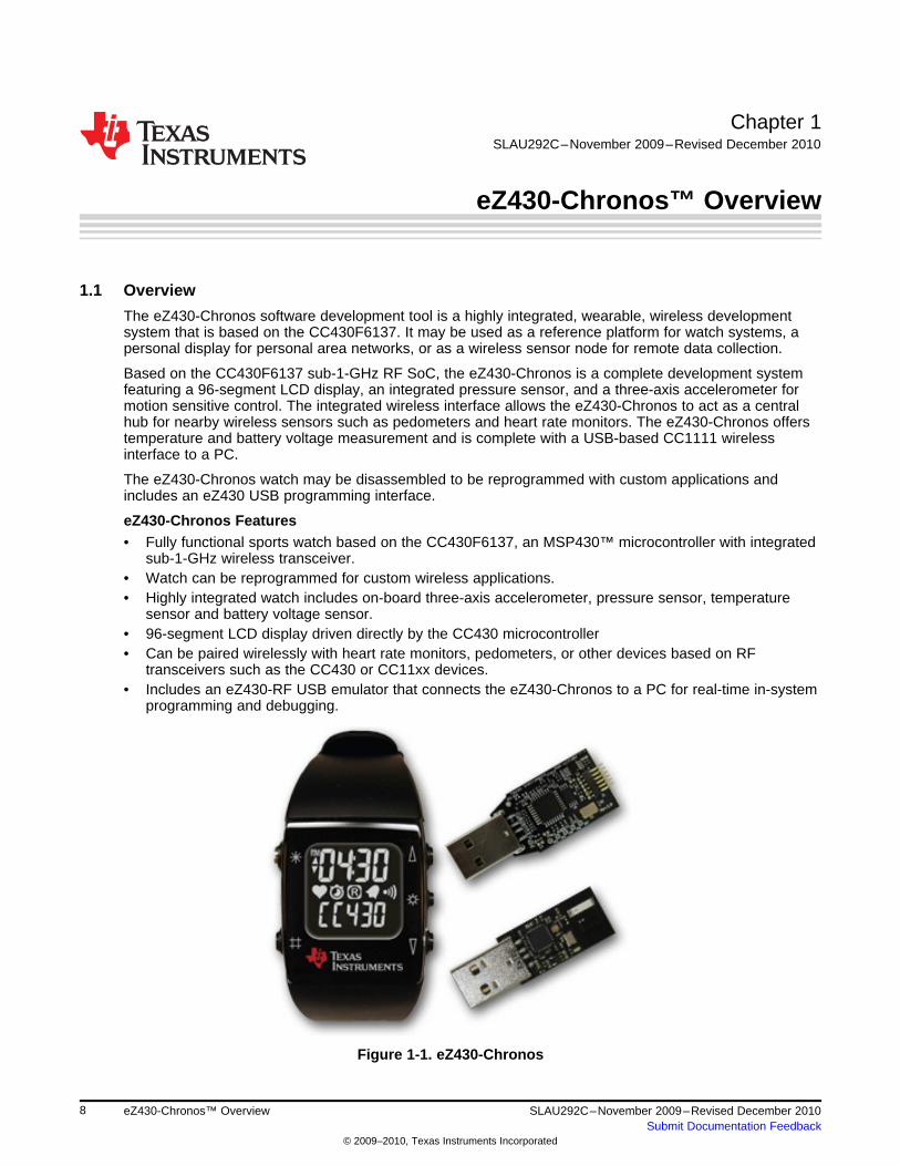
The eZ430-Chronos software development tool is a highly integrated, wearable, wireless developmentsystem that is based on the CC430F6137. It may be used as a reference platform for watch systems, apersonal display for personal area networks, or as a wireless sensor node for remote data collection.
Based on the CC430F6137 sub-1-GHz RF SoC, the eZ430-Chronos is a complete development systemfeaturing a 96-segment LCD display, an integrated pressure sensor, and a three-axis accelerometer formotion sensitive control. The integrated wireless interface allows the eZ430-Chronos to act as a centralhub for nearby wireless sensors such as pedometers and heart rate monitors. The eZ430-Chronos offerstemperature and battery voltage measurement and is complete with a USB-based CC1111 wirelessinterface to a PC.
The eZ430-Chronos watch may be disassembled to be reprogrammed with custom applications andincludes an eZ430 USB programming interface.
eZ430-Chronos Features• Fully functional sports watch based on the CC430F6137, an MSP430™ microcontroller with integrated
sub-1-GHz wireless transceiver.• Watch can be reprogrammed for custom wireless applications.• Highly integrated watch includes on-board three-axis accelerometer, pressure sensor, temperature
sensor and battery voltage sensor.• 96-segment LCD display driven directly by the CC430 microcontroller• Can be paired wirelessly with heart rate monitors, pedometers, or other devices based on RF
transceivers such as the CC430 or CC11xx devices.• Includes an eZ430-RF USB emulator that connects the eZ430-Chronos to a PC for real-time in-system
programming and debugging.
Figure 1-1. eZ430-Chronos
8 eZ430-Chronos™ Overview SLAU292C–November 2009–Revised December 2010Submit Documentation Feedback
© 2009–2010, Texas Instruments Incorporated
www.ti.com Kit Contents
1.2 Kit Contents• One eZ430-Chronos watch (battery included)• One eZ430-RF USB debugging interface• One CC1111 USB RF access point• One mini Phillips screwdriver• Two spare screws• One MSP430™ development tool CD containing documentation and development software
– eZ430-Chronos™ Windows® PC-Software and Source Code SLAC341– eZ430-Chronos™ Linux® PC-Software and Source Code SLAC388– eZ430-Chronos™ Development Tool User's Guide SLAU292– eZ430-RF2500 Development Tool User's Guide SLAU227– CC430 Family User's Guide SLAU259– Code Composer Studio™ v4.2 Core Edition CCS Mediawiki– Code Composer Studio™ v4.2 User’s Guide for MSP430 SLAU157– IAR Embedded Workbench™ KickStart™ SLAC050– IAR Embedded Workbench™ User's Guide for MSP430 SLAU138
NOTE: For the latest software and documentation, visit www.ti.com/chronos orwww.ti.com/chronoswiki.
9SLAU292C–November 2009–Revised December 2010 eZ430-Chronos™ OverviewSubmit Documentation Feedback
© 2009–2010, Texas Instruments Incorporated
Chapter 2SLAU292C–November 2009–Revised December 2010
Getting Started
2.1 Using the eZ430-Chronos Watch Stand Alone
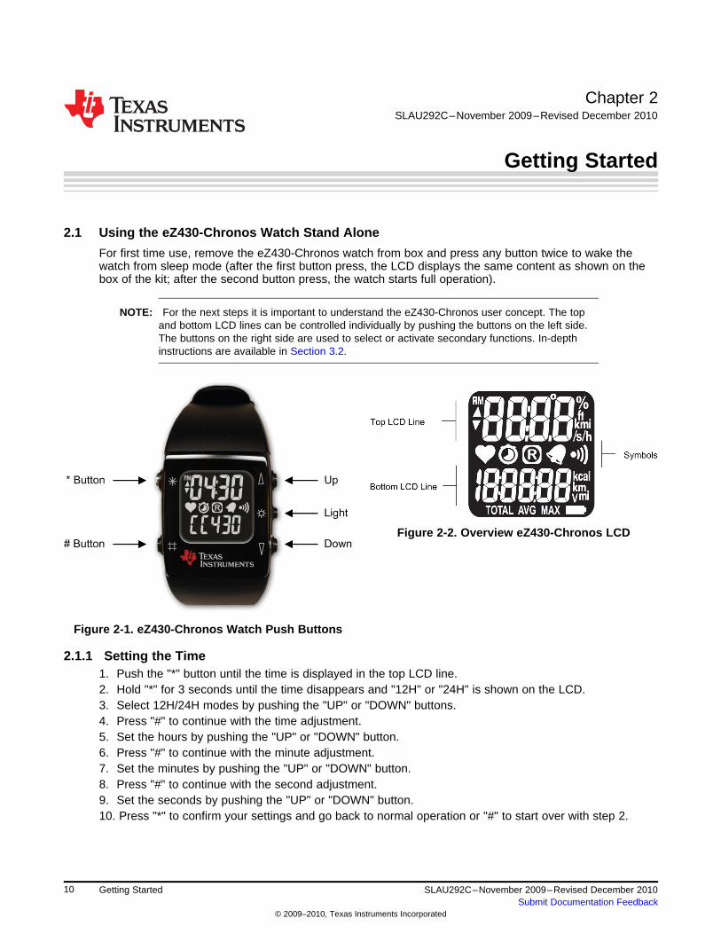
For first time use, remove the eZ430-Chronos watch from box and press any button twice to wake thewatch from sleep mode (after the first button press, the LCD displays the same content as shown on thebox of the kit; after the second button press, the watch starts full operation).
NOTE: For the next steps it is important to understand the eZ430-Chronos user concept. The topand bottom LCD lines can be controlled individually by pushing the buttons on the left side.The buttons on the right side are used to select or activate secondary functions. In-depthinstructions are available in Section 3.2.
Figure 2-2. Overview eZ430-Chronos LCD
Figure 2-1. eZ430-Chronos Watch Push Buttons
2.1.1 Setting the Time1. Push the "*" button until the time is displayed in the top LCD line.2. Hold "*" for 3 seconds until the time disappears and "12H" or "24H" is shown on the LCD.3. Select 12H/24H modes by pushing the "UP" or "DOWN" buttons.4. Press "#" to continue with the time adjustment.5. Set the hours by pushing the "UP" or "DOWN" button.6. Press "#" to continue with the minute adjustment.7. Set the minutes by pushing the "UP" or "DOWN" button.8. Press "#" to continue with the second adjustment.9. Set the seconds by pushing the "UP" or "DOWN" button.10. Press "*" to confirm your settings and go back to normal operation or "#" to start over with step 2.
10 Getting Started SLAU292C–November 2009–Revised December 2010Submit Documentation Feedback
© 2009–2010, Texas Instruments Incorporated
www.ti.com Using the eZ430-Chronos Watch Stand Alone
NOTE: If no button is pushed for more than 30 seconds, the previous settings are restored.
Alternatively, the time and date may be set wirelessly using the eZ430-Chronos ControlCenter (see Section 3.3.3).
2.1.2 Setting the Date1. Push the "#" button until the date is displayed in the bottom LCD line.2. Hold "#" for 3 seconds until the year flashes on the bottom LCD line.3. Set the year by pushing the "UP" or "DOWN" button.4. Press "#" to continue with the month adjustment.5. Set the month by pushing the "UP" or "DOWN" button.6. Press "#" to continue with the day adjustment.7. Set the day by pushing the "UP" or "DOWN" button.8. Press "*" to confirm your settings and go back to normal operation or "#" to start over with step 3.
NOTE: If no button is pushed for more than 30 seconds, the previous settings are restored.
2.1.3 Feature Overview and Menu Structure
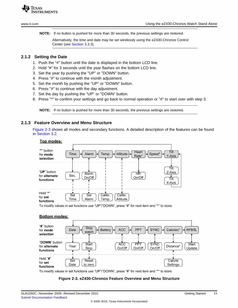
Figure 2-3 shows all modes and secondary functions. A detailed description of the features can be foundin Section 3.2.
Figure 2-3. eZ430-Chronos Feature Overview and Menu Structure
11SLAU292C–November 2009–Revised December 2010 Getting StartedSubmit Documentation Feedback
© 2009–2010, Texas Instruments Incorporated
Install Demo Application, Drivers and Firmware www.ti.com
2.2 Install Demo Application, Drivers and Firmware
The eZ430-Chronos PC software supports Windows® and Linux® (Ubuntu 9.10) operating systems.Download the latest eZ430-Chronos Software and Source Code Installer (SLAC341) for Windows and(SLAC388) for Linux from the eZ430-Chronos web page at www.ti.com/chronos or open it from theincluded CD.
2.2.1 Windows® Installation1. Unzip the archive and run Chronos-Setup.exe.2. Respond to the prompts to install the software. During the installation a separate window opens for the
Windows driver installation. Accept the driver installation.
NOTE: The eZ430-Chronos access point driver may not be certified by Microsoft. Therefore,Windows may generate a warning. Allow the driver installation to continue.
3. When installation finishes, connect the eZ430-Chronos RF USB access point to the PC and follow theWindows driver installation (see Section 2.3).
4. If prompted for the driver for the TI CC1111 Low-Power RF to USB CDC Serial Port, allow Windows to'Install the software automatically'. This can be done only if the eZ430-Chronos PC Software packagehas already been installed.
5. Open the eZ430-Chronos Control Center program. A shortcut is available on the Desktop and the StartMenu under Programs > Texas Instruments > eZ430-Chronos > eZ430-Chronos Control Center.
For a detailed driver installation, see Appendix B.
2.2.2 Linux® Installation
The eZ430-Chronos PC software for Linux requires TCL/Tk. If your Linux distribution does not alreadyinclude TCL/Tk yet, install both with the apt-get command:
sudo apt-get install tcl8.5sudo apt-get install tk8.5
To generate keyboard events and mouse clicks through the watch buttons, xdotool is required. Install withthe apt-get command:
sudo apt-get install xdotool
The PC now has the infrastructure for the eZ430-Chronos PC Software. Continue with the eZ430-Chronosinstallation:
1. Unzip the archive and run Chronos-Setup.2. Respond to the prompts to install the software.3. Insert the eZ430-Chronos RF USB access point to the PC.4. Check the /dev directory for new entry /dev/ttyACMx, where x specifies the number of the port.5. Set the COM variable in eZ430-Chronos_CC_1_2.tcl and eZ430-Chronos_Datalogger_1_2.tcl if the
USB RF access point is not mounted as /dev/ttyACM06. Set script files to executable: chmod u+x ./eZ430-Chronos_CC_1_2.tcl and chmod u+x ./eZ430-
Chronos_Datalogger_1_2.tcl7. Launch the script from terminal ./eZ430-Chronos_CC_1_2.tcl
NOTE: Linux is supported by the eZ430-Chronos Control Center and eZ430-Chronos Data LoggerPC applications. The eZ430-Chronos software package also contains all source code for thewatch module and access point, which are provided for Code Composer Studio and the IAREmbedded Workbench. Both IDEs are currently only available for Windows. CrossWorksfrom Rowley Associates supports Linux and MacOS but requires manual project setup.MSPGCC may be used for Linux as well.
12 Getting Started SLAU292C–November 2009–Revised December 2010Submit Documentation Feedback
© 2009–2010, Texas Instruments Incorporated
www.ti.com Using the eZ430-Chronos Watch With a PC
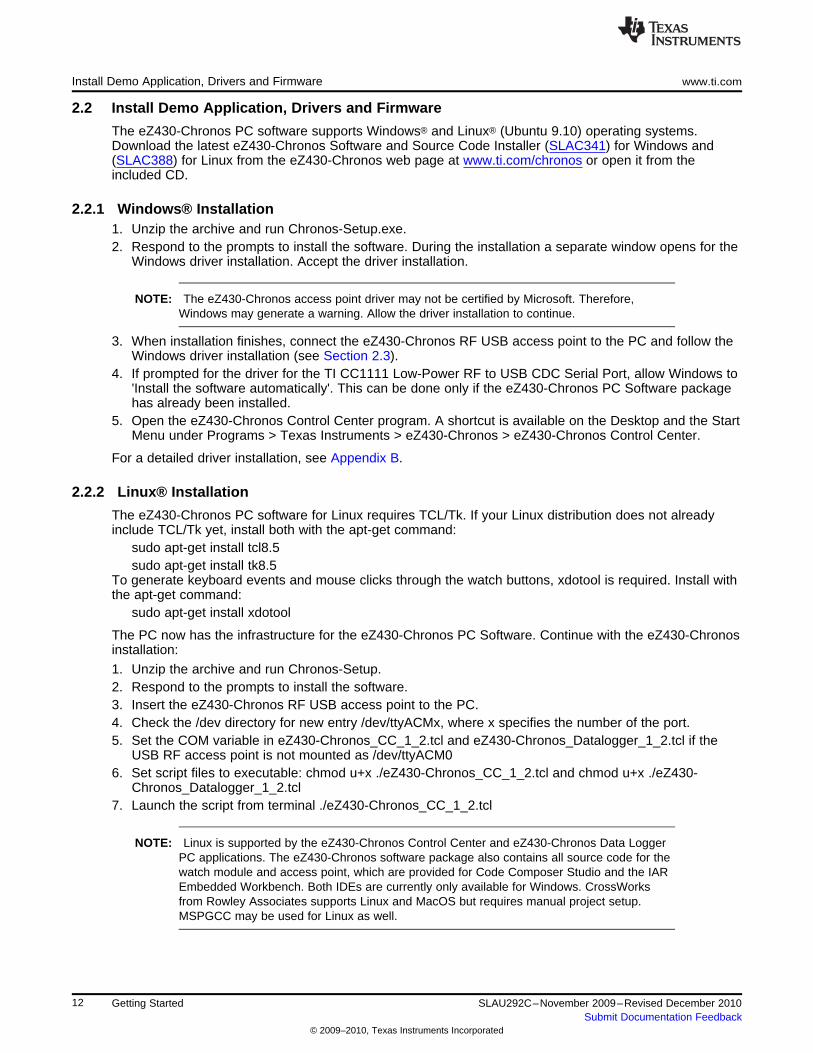
2.3 Using the eZ430-Chronos Watch With a PC1. The Control Center provides a variety of demos. A detailed description can be found in Section 3.3.
The following sections describe only how to use the eZ430-Chronos watch to control the mousepointer on your PC and to use it to control PowerPoint® presentation software.
Figure 2-4. eZ430-Chronos Control Center
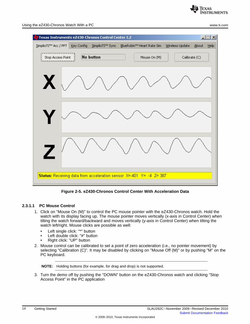
2.3.1 Transmission of Acceleration Data and Button Pushes1. Select "SimpliciTI Acc/PPT" tab.2. Click on "Start Access Point" to start PC. The control center status line displays "Access point started.
Now start watch in ACC, PPT or synch mode" when the PC is ready3. Select "ACC" mode in the bottom LCD line of the eZ430-Chronos watch and active the data
transmission by pressing the "DOWN" button. The watch connects to the PC (this may take a fewseconds) and starts transmitting 3-Axis acceleration values
4. Once connected, the Control Center status bar reports Receiving data from acceleration sensor andthe values according to the axis. The graphs display the acceleration data of the watch for each axis.
13SLAU292C–November 2009–Revised December 2010 Getting StartedSubmit Documentation Feedback
© 2009–2010, Texas Instruments Incorporated
Using the eZ430-Chronos Watch With a PC www.ti.com
Figure 2-5. eZ430-Chronos Control Center With Acceleration Data
2.3.1.1 PC Mouse Control1. Click on "Mouse On (M)" to control the PC mouse pointer with the eZ430-Chronos watch. Hold the
watch with its display facing up. The mouse pointer moves vertically (x-axis in Control Center) whentilting the watch forward/backward and moves vertically (y-axis in Control Center) when tilting thewatch left/right. Mouse clicks are possible as well:
• Left single click: "*" button• Left double click: "#" button• Right click: "UP" button
2. Mouse control can be calibrated to set a point of zero acceleration (i.e., no pointer movement) byselecting "Calibration (C)". It may be disabled by clicking on "Mouse Off (M)" or by pushing "M" on thePC keyboard.
NOTE: Holding buttons (for example, for drag and drop) is not supported.
3. Turn the demo off by pushing the "DOWN" button on the eZ430-Chronos watch and clicking "StopAccess Point" in the PC application
14 Getting Started SLAU292C–November 2009–Revised December 2010Submit Documentation Feedback
© 2009–2010, Texas Instruments Incorporated
www.ti.com Using the eZ430-Chronos Watch With a PC
2.3.1.2 PowerPoint Control
The Control Center allows the user to map button pushes on the watch into keystrokes on the PC. Thedefault setting is PowerPoint control, which allows switching slides forward/backward and to start the slideshow.
1. Select "SimpliciTI Acc/PPT tab.2. Click on "Start Access Point" to start linking. The control center status line displays "Access point
started".3. Select "PPt" mode in the bottom LCD line of the eZ430-Chronos watch and activate the RF link by
pressing the "DOWN" button. The watch connects to the PC, this may take a moment.4. Once connected, the Control Center status bar show when a button is pushed.5. Open a PowerPoint presentation. Press "#" to go to presentation mode (slide show - F5), "UP" to
switch to next slide (right arrow key) and "*" (left arrow key) to switch to previous slide.
NOTE: To avoid bouncing of the watch buttons, a delay of 0.6 s between transmissions isimplemented; i.e., if a button is pressed twice within less than 0.6, it is translated into onekeystroke only.
The eZ430-Chronos Control Center allows to the user to define other short cuts; for example,to control a music or video player. See Section 3.3.2 for details.
For troubleshooting tips, see Appendix A, Frequently Asked Questions.
15SLAU292C–November 2009–Revised December 2010 Getting StartedSubmit Documentation Feedback
© 2009–2010, Texas Instruments Incorporated
Chapter 3SLAU292C–November 2009–Revised December 2010
eZ430-Chronos Software
3.1 Overview
This chapter describes the software that is included in the eZ430-Chronos kit. Different projects and PCuser interfaces are available:
1. eZ430-Chronos sports watch software2. Control Center PC software for Windows and Linux3. eZ430-Chronos watch data logger4. Data logger PC software for Windows and Linux
Many features of the eZ430-Chronos kit are based on TI's SimpliciTI protocol stack. However, the eZ430-Chronos watch can also be used as a heart rate monitor. For this purpose, the BlueRobin™ ultra-low-power protocol stack can be used. (1) is implemented on the watch and USB access point. The protocolstacks are selected automatically, depending on which feature is used.
3.2 eZ430-Chronos Sports Watch Software
The sports watch firmware (default) provides a broad set of features. Besides basic watch functions suchas time, date, alarm and stopwatch advanced sports watch features such as an altimeter, heart ratemonitor*, calorie*, vertical speed* and distance information* are available. The internal accelerometerprovides acceleration data on the watch LCD and allows controlling a PC by transferring the sensor'smeasurements. The watch can also be used to control PowerPoint or other PC software with its buttons.
User concept:
The different features are either available in the top or bottom LCD line.
There are three user modes available: Modes such as Time or Date,... , Secondary Functions, whichallow (de-)activation of features (for example, to start or stop the stopwatch, enable/disable alarm, etc.),and the Set Functions, which allow changing settings (setting time, date,...) or resetting the stopwatch forexample (see Figure 3-1).
• Modes: The different modes can be selected by using the button left of the corresponding LCD line.Examples:The "*" button allows selecting the top line modeThe "#" button allows changing the bottom line modes
• Secondary Functions: Secondary functions provide an extension to the selected mode and areavailable through the button to the right of the corresponding LCD line.Examples:Toggling between time (HH:MM) and seconds (.SS) in time mode: push "UP" button to toggle betweenmodes.Start/Stop in stopwatch mode: push "DOWN" to start or stop stopwatch
• Set Functions: Time, date and other options can be set by holding the button left of the correspondingLCD line.Examples:Setting the time (shown in top LCD line): hold the "*" button to enter the time set menu.Resetting the stopwatch (shown in bottom LCD line): hold the "#" button to reset.
(1) BlueRobin is available from BM wireless at www.bmwireless.com.
16 eZ430-Chronos Software SLAU292C–November 2009–Revised December 2010Submit Documentation Feedback
© 2009–2010, Texas Instruments Incorporated
www.ti.com eZ430-Chronos Sports Watch Software
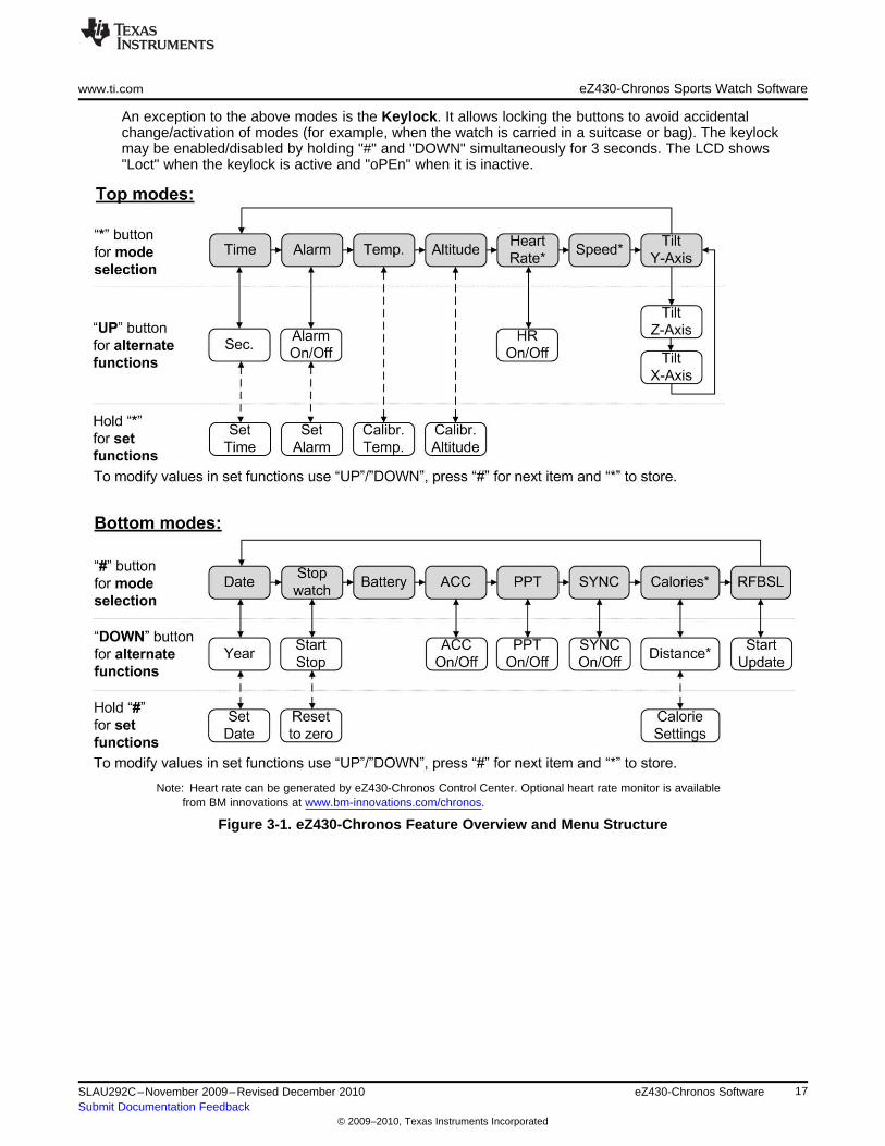
An exception to the above modes is the Keylock. It allows locking the buttons to avoid accidentalchange/activation of modes (for example, when the watch is carried in a suitcase or bag). The keylockmay be enabled/disabled by holding "#" and "DOWN" simultaneously for 3 seconds. The LCD shows"Loct" when the keylock is active and "oPEn" when it is inactive.
Note: Heart rate can be generated by eZ430-Chronos Control Center. Optional heart rate monitor is availablefrom BM innovations at www.bm-innovations.com/chronos.
Figure 3-1. eZ430-Chronos Feature Overview and Menu Structure
17SLAU292C–November 2009–Revised December 2010 eZ430-Chronos SoftwareSubmit Documentation Feedback
© 2009–2010, Texas Instruments Incorporated
eZ430-Chronos Sports Watch Software www.ti.com
3.2.1 Detailed Feature Overview - Modes Using the Top LCD Line
3.2.1.1 Time Mode
Press "*" until the time mode is active (see Figure 3-1 for details).
Secondary function: Seconds. Press "UP" to activate the alternative display. To return to the HH:MMmode, push the "UP" button again.
Set function: Setting the time.
1. Hold "*" for 3 seconds until the time disappears and "12H" or "24H" is shown on the LCD2. Select 12H/24H modes by pushing the "UP" or "DOWN" buttons3. Press "#" to continue with the time adjustment4. Set the hours by pushing the "UP" or "DOWN" button5. Press "#" to continue with the minutes adjustment6. Set the minutes by pushing the "UP" or "DOWN" button7. Press "#" to continue with the second adjustment8. Set the seconds by pushing the "UP" or "DOWN" button9. Press "*" to confirm your settings and go back to normal operation or "#" to start over with step 2
NOTE: If you do not press any button for more than 30 seconds, the previous settings are restored.
3.2.1.2 Alarm Mode
Press "*" until the alarm mode is active (see Figure 3-1 for details). The alarm mode can be distinguishedfrom time mode, as an alarm symbol (bell) flashes when the alarm time is displayed.
Secondary function: Alarm on/off. Press "UP" to enable/disable the alarm. The settings are confirmed by"on" and "off" in the top LCD line. The bell icon stays on in all other modes when the alarm is enabled anddoes not appear when it is disabled.
Set function: Setting the alarm time.
1. Hold "*" for 3 seconds until the alarm time hour starts to flash2. Set the hours by pushing the "UP" or "DOWN" button3. Press "#" to continue with the minutes adjustment4. Set the minutes by pushing the "UP" or "DOWN" button5. Press "*" to confirm your settings and go back to normal operation or "#" to start over with step 2
NOTE: If you do not press any button for more than 30 seconds, the previous settings are restored.
18 eZ430-Chronos Software SLAU292C–November 2009–Revised December 2010Submit Documentation Feedback
© 2009–2010, Texas Instruments Incorporated
www.ti.com eZ430-Chronos Sports Watch Software
3.2.1.3 Temperature Mode
Press "*" until the temperature mode is active (see Figure 3-1 for details). The temperature can be shownin degree Celsius or Fahrenheit. The selection depends on the time mode setting. In 12H mode, thetemperature is shown in degrees Fahrenheit, in 24H mode in degrees Celsius. The temperature ismeasured in 1-second intervals. Positive temperatures are marked with a small arrow pointing up in theupper LCD line, left of the temperature. An arrow pointing down indicated temperatures below zero.
Secondary function: None
Set function: Temperature calibration (can also calibrated from PC software in Sync mode, seeSection 3.3).
1. Hold "*" for 3 seconds until the temperature starts to flash2. Set the temperatures by pushing the "UP" or "DOWN" button3. Press "*" to confirm your settings
NOTE: The temperature is measured inside the watch right inside the CC430 device. When thewatch is worn, the temperature of the watch may be different due to the body heat. Foraccurate temperature measurements, do not wear the watch and allow a sufficient amount oftime for the watch to adapt to the surrounding temperature.
3.2.1.4 Altimeter Mode
Press "*" until the altimeter alarm mode is active (see Figure 3-1 for details). The altitude can be shown inmetric or imperial units. In 12H time mode, the altitude is shown in imperial, in 24H time mode in metricunits. The altitude is measured only when the altimeter mode is active, and measurement happen inintervals of 1 second.
The implementation of the altitude algorithm is done according to the VTI's application report AN33 withoutany additional low-power optimizations. Therefore, the altimeter is active only in altimeter mode. Inaddition, a timeout deactivates the measurements after 60 minutes. Altitudes above sea level areindicated with a small arrow pointing up in the upper LCD line, left of the altitude. Altitudes below sea levelare indicated with a small arrow pointing down.
The altimeter algorithm is based on the air pressure and the ambient temperature. Therefore, changes inair pressure affect the altitude accuracy. For precise measurements, the altimeter needs to be calibratedmanually upon weather changes.
NOTE: For most accurate altitude measurement, the watch needs to have ambient temperature(i.e., should not be worn directly on the arm), as temperature is part of the altitudemeasurement (see Section 3.2.1.3).
Secondary function: Re-activate altimeter after timeout
Set function: Altitude calibration
1. Hold "*" for 3 seconds until the altitude starts to flash2. Set the altitude by pushing the "UP" or "DOWN" button3. Press "*" to confirm your settings.
19SLAU292C–November 2009–Revised December 2010 eZ430-Chronos SoftwareSubmit Documentation Feedback
© 2009–2010, Texas Instruments Incorporated
eZ430-Chronos Sports Watch Software www.ti.com
3.2.1.5 Heart Rate Mode - RF (2)
Press "*" until the heart icon appears on the display i.e. heart rate mode is active (see Figure 3-1 fordetails). When this mode is active, heart rate is shown and burned calories are determined (additionalsettings must be made for first time use, see Section 3.2.2.7). For information on how to use the chestbelt, see to the documentation included with the heart rate monitor device.
NOTE: This mode requires a heart rate monitor (chest belt) that is not included in this kit, butavailable from BM innovations, Germany (see www.bm-innovations.com/chronos). However,a heart rate can be simulated without a chest belt by the eZ430-Chronos Control Center, seeSection 3.3 for details.
While almost all other eZ430-Chronos functions are based on TI's SimpliciTI protocol, theheart rate monitoring uses BlueRobin, an ultra-low-power low-data-rate wirelesscommunication protocol from BM innovations.
Secondary function: Heart rate display on/off. Press "UP" to enable/disable the heart rate monitoring.Once a connection is established, the heart rate is shown on the top LCD line
Set function: None
3.2.1.6 Speed Mode - RF (3)
Press "*" until the "mi/h" or "km/h" icon is shown on the display; i.e., the speed mode is active (seeFigure 3-1). Your running speed is shown on the LCD top line.
NOTE: This mode requires a heart rate monitor (chest belt) which includes an accelerometer todetermine running speed. Visit BM innovations at www.bm-innovations.com/chronos foravailable additions. However, speed can be simulated without a chest belt by the eZ430-Chronos Control Center, see Section 3.3.4 for details.
While almost all other eZ430-Chronos functions are based on TI's SimpliciTI protocol, thespeed mode uses BlueRobin, an ultra-low-power low-data-rate wireless communicationprotocol from BM innovations.
Secondary function: None
Set function: None
3.2.1.7 Tilt Mode
Press "*" until the tilt mode is active (see Figure 3-1). The acceleration is shown in G (9.81 m/s2) for allthree axes. After entering the tilt mode, the y-axis acceleration is shown by default, and the z-axis or x-axis can be selected. Positive acceleration values are marked with a small arrow pointing up in the topLCD line, left of the acceleration. Negative acceleration values are marked with a small arrow pointingdown. After 60 minutes, a timeout deactivates the measurements.
Secondary function: Select axis. The default is y-axis, followed by z-axis and x-axis.
Set function: None(2) Additional accessory or eZ430-Chronos Control Center heart rate simulation required.(3) Additional accessory or eZ430-Chronos Control Center heart rate simulation required.
20 eZ430-Chronos Software SLAU292C–November 2009–Revised December 2010Submit Documentation Feedback
© 2009–2010, Texas Instruments Incorporated

www.ti.com eZ430-Chronos Sports Watch Software
3.2.2 Detailed Feature Overview - Modes Using the Bottom LCD Line
3.2.2.1 Date Mode
Press "#" until the date mode is active (see Figure 3-1).
Secondary function: Year. Press "DOWN" to activate the alternative display. To return to day and month,push the "DOWN" button again.
Set function: Setting the date
1. Push the "#" button until the date is displayed in the bottom LCD line.
2. Hold "#" for 3 seconds until the year flashes on the bottom LCD line.
3. Set the year by pushing the "UP" or "DOWN" button.
4. Press "#" to continue with the month adjustment.
5. Set the month by pushing the "UP" or "DOWN" button.
6. Press "#" to continue with the day adjustment.
7. Set the day by pushing the "UP" or "DOWN" button. Press "*" to confirm your settings and go back tonormal operation or "#" to start over with step 3.
NOTE: If no key is pressed for more than 30 seconds, the previous settings are restored.
3.2.2.2 Stopwatch Mode
Press "#" until the stopwatch mode is active (see Figure 3-1). It supports up time intervals up to 19 hours,59 minutes and 59 seconds. For the first 20 minutes, the resolution is 1/100 second, after 20 minutes theresolution changes to 1 second.
Secondary function: Start/stop. Press "DOWN" to start or stop the stopwatch
Set function: Reset stopwatch.
Hold the "#" button until the stopwatch is set to zero
3.2.2.3 Battery Voltage Mode
Press "#" until the battery voltage is shown (see Figure 3-1). It is updated once per minute.
Secondary function: None
Set function: None
3.2.2.4 Acceleration Mode - RF
This mode requires the eZ430-Chronos Control Center PC software.
Press "#" until "ACC" is shown on the LCD (see Figure 3-1). This mode provide a continuous transmissionof 3D acceleration from the watch using TI's SimpliciTI protocol stack. In addition, the watch transmits asignal when the "#", "*" or "UP" buttons are pushed.
Secondary function: Start/stop transmission of acceleration data. Pushing "DOWN" starts/stops thepairing process or stop the transmission (the access point on the PC must be started first from the eZ430-Chronos Control Center (see Section 3.3.1). The RF icon on the LCD flashes when the radio is active. Ifthe pairing fails, it disappears. The top LCD line shows the time during the pairing and until the datatransmission is disabled.
Set function: None
21SLAU292C–November 2009–Revised December 2010 eZ430-Chronos SoftwareSubmit Documentation Feedback
© 2009–2010, Texas Instruments Incorporated
eZ430-Chronos Sports Watch Software www.ti.com
3.2.2.5 PowerPoint Mode - RF
This mode requires the eZ430-Chronos Control Center PC software.
Press "#" until "PPt" is shown (see Figure 3-1). This mode allows control of a PowerPoint presentation bytranslating button pushes on the watch into keystrokes of the PC keyboard. No acceleration or other datais transmitted. The default settings are:
• "#" - Go to presentation mode (F5)• "*" - Previous slide (Left)• "UP" - Next slide (Right)
The Control Center allows user defined key settings (including combinations) - see Section 3.3.2.
Secondary function: Start/stop transmission of button pushes. Pushing "DOWN" starts/stops the pairingprocess or stops the transmission (the access point on the PC must be started from the eZ430-ChronosControl Center (see Section 3.3.1). The RF icon on the LCD flashes when the radio is active; if pairingfails, the icon disappears. The top LCD line shows the time during the pairing until the data transmission isdisabled.
Set function: None
3.2.2.6 Sync Mode - RF
This mode requires the eZ430-Chronos Control Center PC software.
Press "#" until "SYnC" is shown (see Figure 3-1). This mode allows doing a variety of watch settingsconveniently from the eZ430-Chronos Control Center PC software over the air (see Section 3.3.3).
• Time settings• Date settings• Altitude calibration• Temperature calibration
Secondary function: Start/stop link for Sync Mode. Pushing "DOWN" starts/stops the pairing process orstop the link (the access point on the PC must be started first from the eZ430-Chronos Control Center(see Section 3.3.3). The RF icon on the LCD flashes when the radio is active. If the pairing fails, itdisappears. After a successfully received message, the LCD shows "DONE". The top LCD line is offduring the pairing and until the Sync Mode is disabled.
Set function: None
22 eZ430-Chronos Software SLAU292C–November 2009–Revised December 2010Submit Documentation Feedback
© 2009–2010, Texas Instruments Incorporated
www.ti.com eZ430-Chronos Sports Watch Software
3.2.2.7 Calorie/Distance Mode - RF (4)
Press "#" until the "kcal" icon appears (see Figure 3-1). This mode shows the amount of calories that wereburned while exercising, if the optional chest belt is used and heart rate mode is active. This mode alsoprovides the distance (for example, when running) if a chest belt with build-in accelerometer is used. Foraccurate calorie determination, users need to set their sex and weight.
Secondary function: Distance. Press "DOWN" to activate the alternative display. To return to CalorieMode, push the "DOWN" button again.
Set function: (Re-)setting calories and setting user weight and sex.
1. Push the "#" button until the calories is displayed in the bottom LCD line2. Hold "#" for 3 seconds until the calorie value flashes on the bottom LCD line3. (Re-)set the calories by pushing "UP" or "DOWN"4. Press "#" to continue with the user sex adjustment5. Set the user sex by pushing "UP" or "DOWN"6. Press "#" to continue with user weight adjustment7. Set the user weight (lb in 12H time mode, kg in 24H time mode) by pushing "UP" or "DOWN"8. Press "*" to confirm your settings and go back to normal operation or "#" to start over with step 3
NOTE: If no key is pressed for more than 30 seconds, the previous settings are restored.
3.2.2.8 Wireless Update - RF
This mode requires the eZ430-Chronos Control Center PC software.
Press "#" until the "rFbSL" is shown (see Figure 3-1). This mode allows updating the firmware of theeZ430-Chronos watch wirelessly.
Secondary function: Start/re-start update process. Push "DOWN" once to switch to the confirmationmenu "CONF". Pushing "DOWN" again starts/re-starts the update process (the wireless update on the PCmust be started from the eZ430-Chronos Control Center first (see Section 3.3.1)). At the beginning of theupdate the LCD shows "rAM" for a few seconds. During this time, the actual updater software isdownloaded from the PC to the RAM of the CC430 on the watch. This program contains all memory writeand LCD routines. Once this transfer was finished, the code is executed from RAM. At this point, thedownload of the actual firmware file is started. The LCD shows the progress in percent on the upper LCDline. Once the transfer was complete successfully, a reset starts the software on the watch. SeeSection 3.6.3 for details.
NOTE: Whenever the wireless update was activated on the watch, it only returns to the mainapplication with a reset, regardless if an update was performed or not. Time, data, alarm andother RAM-based data are lost.
(4) Additional accessory or eZ430-Chronos Control Center heart rate simulation required.
23SLAU292C–November 2009–Revised December 2010 eZ430-Chronos SoftwareSubmit Documentation Feedback
© 2009–2010, Texas Instruments Incorporated
eZ430-Chronos Control Center PC Software www.ti.com
3.3 eZ430-Chronos Control Center PC Software
The eZ430-Chronos Control Center software provides several features demonstrating the wirelesscapabilities of the kit on Windows and Linux PCs. Different RF protocol stacks are automatically selectedfor use, depending on the function. Available features:
• 3D acceleration graph with PC mouse control• Wireless remote control / PowerPoint control• Time, date and calibration data synchronization tool• Heart rate and speed simulator• Wireless firmware update
NOTE: Connect the USB RF access point to the PC before launching the Control Center software.For first time use, you may also have to wait until Windows has finished the access pointdriver installation.
In case of problems on Windows PCs, please check if the settings for the RF access pointare correct in the Windows Device Manager Start > Control Panel > System > Hardware >Device Manager. The RF access point is listed under Ports (COM & LPT) as TI CC1111Low-Power RF to USB CDC Serial Port. The port settings should be:
• Baud Rate: 115200
• Data bits: 8
• Parity: None
• Stop bits: 1
• Flow control: None
In case of problems on Linux PCs, ensure that the correct tty setting is specified. Check /devfor the new tty device after plugging in the RF access point. If you see that the RF accesspoint gets assigned to a different device other than ttyACM0, either remove the serial devicethat occupies this slot (for example, a modem), or change the script file variable "com" ineZ430-Chronos_CC_1_2.tcl located in /home/<user name>/Texas Instruments/eZ430-Chronos/Control Center/eZ430-Chronos Control Center.
To launch the Control Center software on a Windows PC, shortcuts are available on the Desktop and inthe Start Menu under Programs > Texas Instruments > eZ430-Chronos > eZ430-Chronos Control Center.
To launch the Control Center software on a Linux PC, browse to /home/<user name>/TexasInstruments/eZ430-Chronos/Control Center/eZ430-Chronos Control Center and run eZ430-Chronos_CC_1_2.tcl.
The different features are grouped onto tabs of the Control Center window. The tabs also indicate whichradio protocol is used.
24 eZ430-Chronos Software SLAU292C–November 2009–Revised December 2010Submit Documentation Feedback
© 2009–2010, Texas Instruments Incorporated
www.ti.com eZ430-Chronos Control Center PC Software
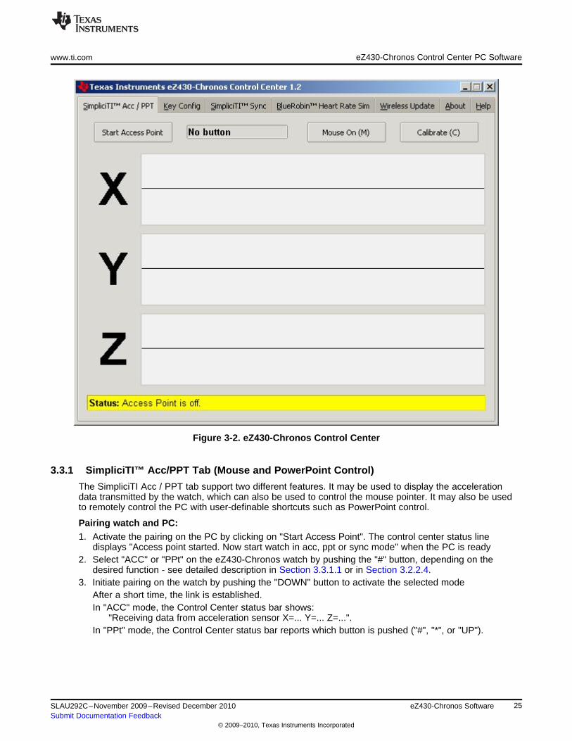
Figure 3-2. eZ430-Chronos Control Center
3.3.1 SimpliciTI™ Acc/PPT Tab (Mouse and PowerPoint Control)
The SimpliciTI Acc / PPT tab support two different features. It may be used to display the accelerationdata transmitted by the watch, which can also be used to control the mouse pointer. It may also be usedto remotely control the PC with user-definable shortcuts such as PowerPoint control.
Pairing watch and PC:1. Activate the pairing on the PC by clicking on "Start Access Point". The control center status line
displays "Access point started. Now start watch in acc, ppt or sync mode" when the PC is ready2. Select "ACC" or "PPt" on the eZ430-Chronos watch by pushing the "#" button, depending on the
desired function - see detailed description in Section 3.3.1.1 or in Section 3.2.2.4.3. Initiate pairing on the watch by pushing the "DOWN" button to activate the selected mode
After a short time, the link is established.In "ACC" mode, the Control Center status bar shows:
"Receiving data from acceleration sensor X=... Y=... Z=...".In "PPt" mode, the Control Center status bar reports which button is pushed ("#", "*", or "UP").
25SLAU292C–November 2009–Revised December 2010 eZ430-Chronos SoftwareSubmit Documentation Feedback
© 2009–2010, Texas Instruments Incorporated

eZ430-Chronos Control Center PC Software www.ti.com
3.3.1.1 Acc Mode
In this mode, the watch constantly transmits acceleration data to the PC. In addition, "#", "*" and "UP"button pushes are transferred. The Control Center software shows the 3D acceleration in graphs.Optionally, mouse control can be activated by clicking on "Mouse On (M)" or by pushing "M" on thekeyboard.
Once active, the PC mouse pointer can be controlled by tilting the watch. Hold the watch with its displayfacing up. The mouse pointer moves vertically (x-axis in Control Center) when tilting the watchforward/backward and move vertically (y-axis in Control Center) when tilting it left/right. Mouse clicks arepossible as well - see below. Mouse control can be calibrated (to set a point of zero acceleration i.e. nopointer movement) by selecting "Calibration (C)". It may be disabled by clicking on "Mouse Off (M)" or bypushing "M" on the PC keyboard.
• Left single click: "*" button• Left double click: "#" button• Right click: "UP" button
NOTE: Holding buttons (for example, to drag and drop) is not supported.
Turn the demo off by pushing the "DOWN" button on the eZ430-Chronos watch and clicking "Stop AccessPoint" in the PC application.
Figure 3-3. eZ430-Chronos Control Center With Acceleration Data
26 eZ430-Chronos Software SLAU292C–November 2009–Revised December 2010Submit Documentation Feedback
© 2009–2010, Texas Instruments Incorporated
www.ti.com eZ430-Chronos Control Center PC Software
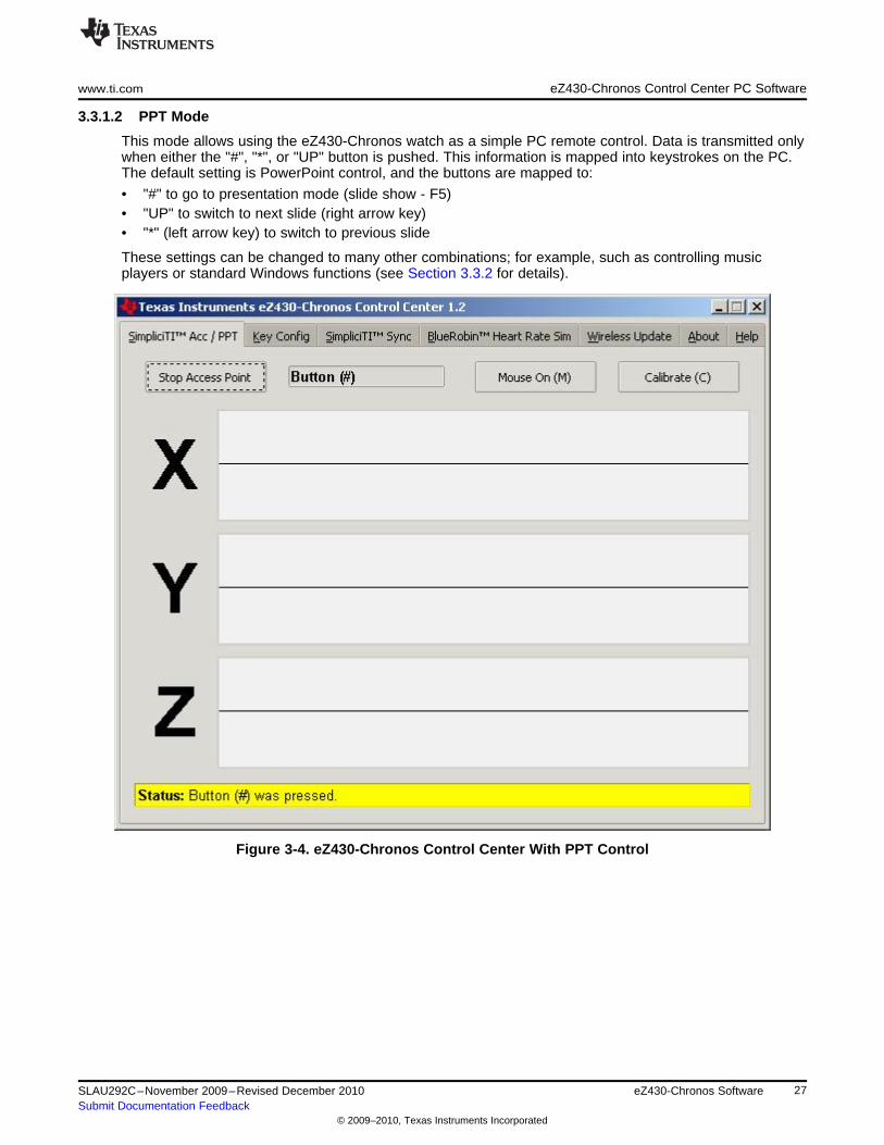
3.3.1.2 PPT Mode
This mode allows using the eZ430-Chronos watch as a simple PC remote control. Data is transmitted onlywhen either the "#", "*", or "UP" button is pushed. This information is mapped into keystrokes on the PC.The default setting is PowerPoint control, and the buttons are mapped to:
• "#" to go to presentation mode (slide show - F5)• "UP" to switch to next slide (right arrow key)• "*" (left arrow key) to switch to previous slide
These settings can be changed to many other combinations; for example, such as controlling musicplayers or standard Windows functions (see Section 3.3.2 for details).
Figure 3-4. eZ430-Chronos Control Center With PPT Control
27SLAU292C–November 2009–Revised December 2010 eZ430-Chronos SoftwareSubmit Documentation Feedback
© 2009–2010, Texas Instruments Incorporated
eZ430-Chronos Control Center PC Software www.ti.com
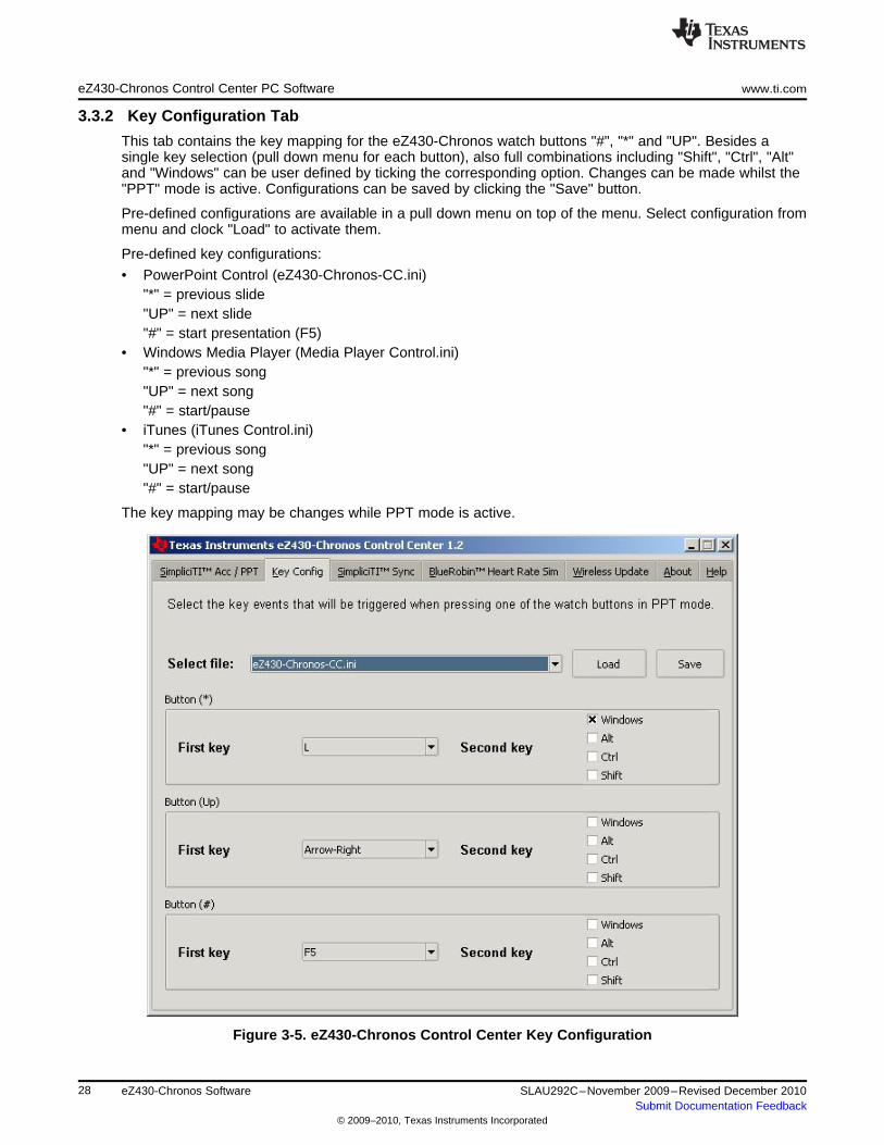
3.3.2 Key Configuration Tab
This tab contains the key mapping for the eZ430-Chronos watch buttons "#", "*" and "UP". Besides asingle key selection (pull down menu for each button), also full combinations including "Shift", "Ctrl", "Alt"and "Windows" can be user defined by ticking the corresponding option. Changes can be made whilst the"PPT" mode is active. Configurations can be saved by clicking the "Save" button.
Pre-defined configurations are available in a pull down menu on top of the menu. Select configuration frommenu and clock "Load" to activate them.
Pre-defined key configurations:
• PowerPoint Control (eZ430-Chronos-CC.ini)"*" = previous slide"UP" = next slide"#" = start presentation (F5)
• Windows Media Player (Media Player Control.ini)"*" = previous song"UP" = next song"#" = start/pause
• iTunes (iTunes Control.ini)"*" = previous song"UP" = next song"#" = start/pause
The key mapping may be changes while PPT mode is active.
Figure 3-5. eZ430-Chronos Control Center Key Configuration
28 eZ430-Chronos Software SLAU292C–November 2009–Revised December 2010Submit Documentation Feedback
© 2009–2010, Texas Instruments Incorporated
www.ti.com eZ430-Chronos Control Center PC Software
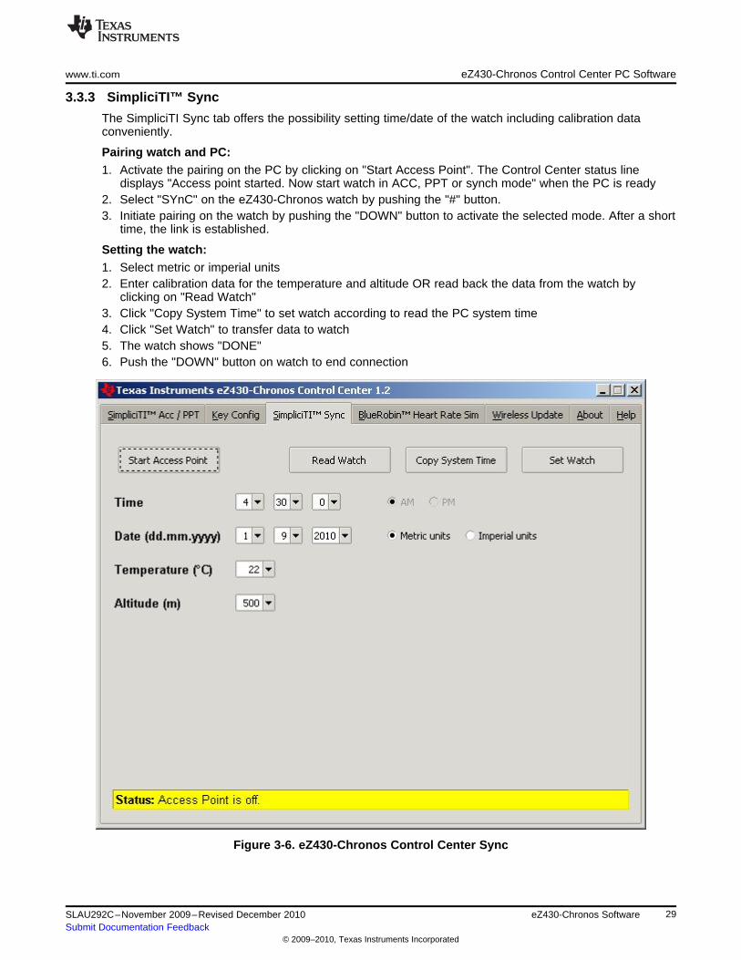
3.3.3 SimpliciTI™ Sync
The SimpliciTI Sync tab offers the possibility setting time/date of the watch including calibration dataconveniently.
Pairing watch and PC:1. Activate the pairing on the PC by clicking on "Start Access Point". The Control Center status line
displays "Access point started. Now start watch in ACC, PPT or synch mode" when the PC is ready2. Select "SYnC" on the eZ430-Chronos watch by pushing the "#" button.3. Initiate pairing on the watch by pushing the "DOWN" button to activate the selected mode. After a short
time, the link is established.
Setting the watch:1. Select metric or imperial units2. Enter calibration data for the temperature and altitude OR read back the data from the watch by
clicking on "Read Watch"3. Click "Copy System Time" to set watch according to read the PC system time4. Click "Set Watch" to transfer data to watch5. The watch shows "DONE"6. Push the "DOWN" button on watch to end connection
Figure 3-6. eZ430-Chronos Control Center Sync
29SLAU292C–November 2009–Revised December 2010 eZ430-Chronos SoftwareSubmit Documentation Feedback
© 2009–2010, Texas Instruments Incorporated
eZ430-Chronos Control Center PC Software www.ti.com
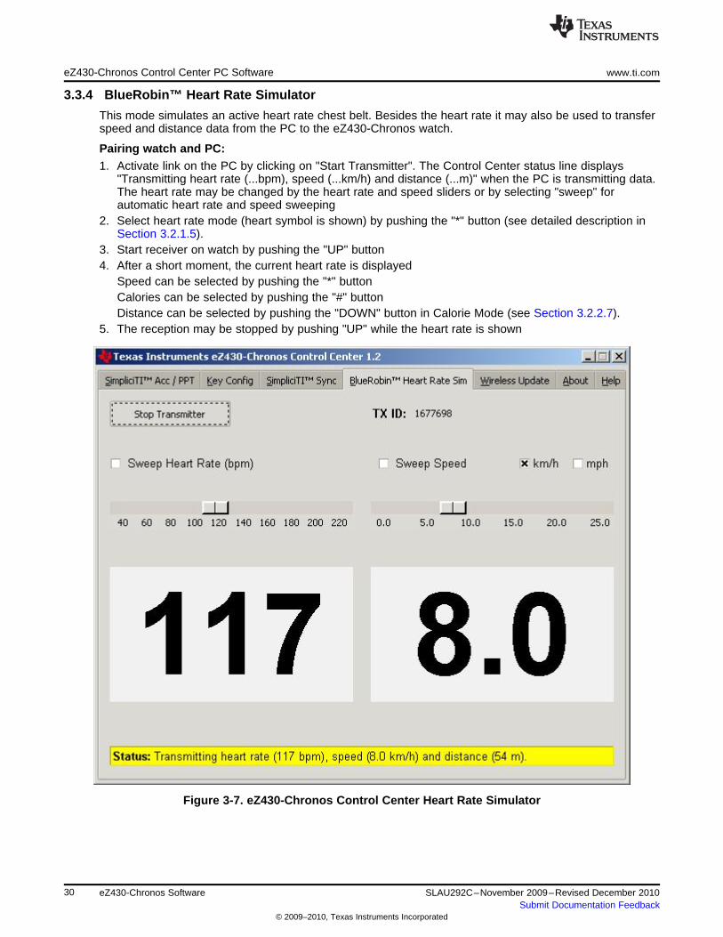
3.3.4 BlueRobin™ Heart Rate Simulator
This mode simulates an active heart rate chest belt. Besides the heart rate it may also be used to transferspeed and distance data from the PC to the eZ430-Chronos watch.
Pairing watch and PC:1. Activate link on the PC by clicking on "Start Transmitter". The Control Center status line displays
"Transmitting heart rate (...bpm), speed (...km/h) and distance (...m)" when the PC is transmitting data.The heart rate may be changed by the heart rate and speed sliders or by selecting "sweep" forautomatic heart rate and speed sweeping
2. Select heart rate mode (heart symbol is shown) by pushing the "*" button (see detailed description inSection 3.2.1.5).
3. Start receiver on watch by pushing the "UP" button4. After a short moment, the current heart rate is displayed
Speed can be selected by pushing the "*" buttonCalories can be selected by pushing the "#" buttonDistance can be selected by pushing the "DOWN" button in Calorie Mode (see Section 3.2.2.7).
5. The reception may be stopped by pushing "UP" while the heart rate is shown
Figure 3-7. eZ430-Chronos Control Center Heart Rate Simulator
30 eZ430-Chronos Software SLAU292C–November 2009–Revised December 2010Submit Documentation Feedback
© 2009–2010, Texas Instruments Incorporated
www.ti.com eZ430-Chronos Control Center PC Software
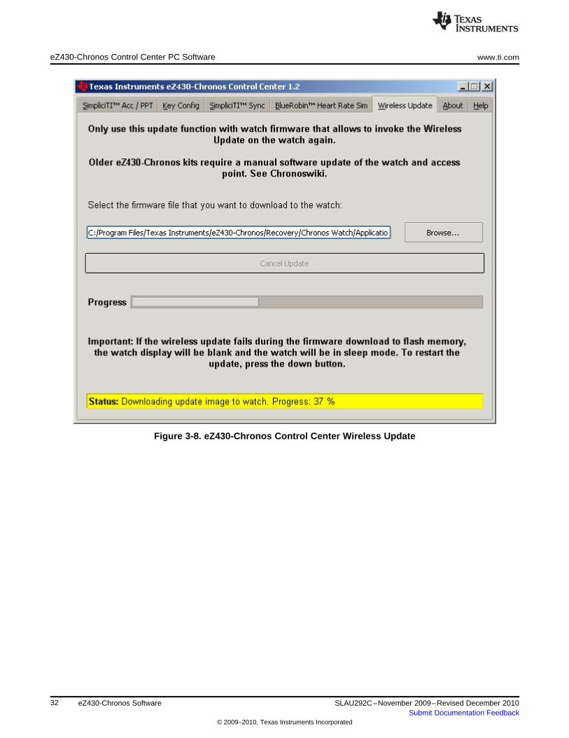
3.3.5 Wireless Update
This mode allows updating the firmware of the eZ430-Chronos watch wirelessly, without disassembling it.
Update procedure:1. Select CC430 flash image (.txt file) by clicking on "Browse...". Example images for the sports watch
software and the data logger application are located for Windows in C:\Program Files\TexasInstruments\eZ430-Chronos\Recovery\eZ430-Chronos Watch\Applications and for Linux in/home/<user name>/Texas Instruments/eZ430-Chronos/Recovery/eZ430-Chronos Watch/Applications.
NOTE: Ensure selecting the correct version of the flash images. If the wrong frequency is selected,no wireless communication is possible anymore. In that case, the watch must be updatedusing the eZ430 debug interface.
Only transfer flash images to the watch, which allow invoking the updater software on thewatch.
The file to be downloaded to the watch must be in TI-TXT format to work with this updateprocedure. This new firmware must reside within the main memory flash (0x8000 to0xFFFF), otherwise the update procedure fails due to boundary checks on the watch side.
2. Activate the update mechanism on the PC by clicking on "Update eZ430-Chronos Watch". The ControlCenter status line displays "Access point started. Now start watch in rFbSL mode" when the PC isready.
3. Select "rFbSL" on the eZ430-Chronos watch by pushing the "#" button4. Initiate update by pushing the "DOWN" button5. After a short moment, the update is started
At the beginning of the update the LCD shows "rAM" for a few seconds. During this time, the actualupdater software is downloaded from the PC to the RAM of the CC430 on the watch. This programcontains all memory write and LCD routines. Once this transfer was finished, the code is executedfrom RAM. At this point, the download of the actual firmware file is started. The LCD shows theprogress in percent on the upper LCD line. Once the transfer was complete successfully, a reset startsthe software on the watch (see Section 3.6.3).
NOTE: If the update fails, it can be activated again by pushing the "DOWN" button again on theeZ430-Chronos watch, given that the wireless update is active in the eZ430-Chronos ControlCenter.
31SLAU292C–November 2009–Revised December 2010 eZ430-Chronos SoftwareSubmit Documentation Feedback
© 2009–2010, Texas Instruments Incorporated
eZ430-Chronos Control Center PC Software www.ti.com
Figure 3-8. eZ430-Chronos Control Center Wireless Update
32 eZ430-Chronos Software SLAU292C–November 2009–Revised December 2010Submit Documentation Feedback
© 2009–2010, Texas Instruments Incorporated
www.ti.com eZ430-Chronos Watch Data Logger
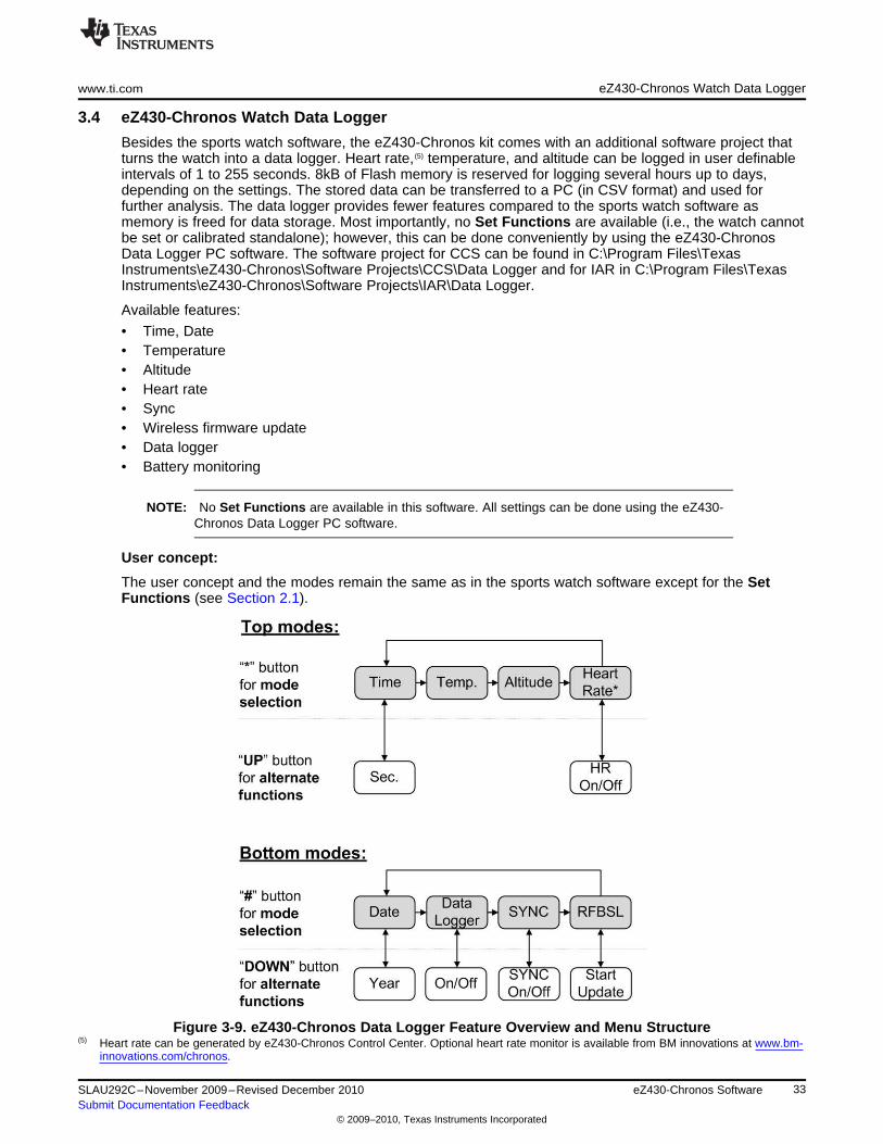
3.4 eZ430-Chronos Watch Data Logger
Besides the sports watch software, the eZ430-Chronos kit comes with an additional software project thatturns the watch into a data logger. Heart rate, (5) temperature, and altitude can be logged in user definableintervals of 1 to 255 seconds. 8kB of Flash memory is reserved for logging several hours up to days,depending on the settings. The stored data can be transferred to a PC (in CSV format) and used forfurther analysis. The data logger provides fewer features compared to the sports watch software asmemory is freed for data storage. Most importantly, no Set Functions are available (i.e., the watch cannotbe set or calibrated standalone); however, this can be done conveniently by using the eZ430-ChronosData Logger PC software. The software project for CCS can be found in C:\Program Files\TexasInstruments\eZ430-Chronos\Software Projects\CCS\Data Logger and for IAR in C:\Program Files\TexasInstruments\eZ430-Chronos\Software Projects\IAR\Data Logger.
Available features:
• Time, Date• Temperature• Altitude• Heart rate• Sync• Wireless firmware update• Data logger• Battery monitoring
NOTE: No Set Functions are available in this software. All settings can be done using the eZ430-Chronos Data Logger PC software.
User concept:
The user concept and the modes remain the same as in the sports watch software except for the SetFunctions (see Section 2.1).
Figure 3-9. eZ430-Chronos Data Logger Feature Overview and Menu Structure(5) Heart rate can be generated by eZ430-Chronos Control Center. Optional heart rate monitor is available from BM innovations at www.bm-
innovations.com/chronos.
33SLAU292C–November 2009–Revised December 2010 eZ430-Chronos SoftwareSubmit Documentation Feedback
© 2009–2010, Texas Instruments Incorporated
Data Logger PC Software www.ti.com
3.4.1 Detailed Feature Overview
As all available modes remain the same in the Data Logger software, only the additions are described inthis section.
3.4.1.1 Data Logger Mode
The data logger mode can be selected by pushing the "*" button until the bottom LCD line shows "dLog". Itmay be enabled/disabled by pushing the "DOWN" button. If the heart rate data logging is selected (seeSection 3.5 ) in data logger PC software, the heart rate monitor is automatically enabled (the RF iconflashes until linked to a heart rate monitor). When active, the record icon on the LCD is on (see Figure 1-1).
NOTE: Connect the USB RF access point to the PC before launching the Control Center software.For first time use, you may also have to wait until Windows has finished the access pointdriver installation.
In case of problems on Windows PCs, please check if the settings for the RF access pointare correct in the Windows Device Manager Start > Control Panel > System > Hardware >Device Manager. The RF access point is listed under Ports (COM & LPT) as TI CC1111Low-Power RF to USB CDC Serial Port. The port settings should be:
• Baud Rate: 115200
• Data bits: 8
• Parity: None
• Stop bits: 1
• Flow control: None
In case of problems on Linux PCs, ensure that the correct tty setting is specified. Check /devfor the new tty device after plugging in the RF access point. If you see that the RF accesspoint gets assigned to a different device other than ttyACM0, either remove the serial devicethat occupies this slot (for example, a modem), or change the script file variable "com" ineZ430-Chronos_Datalogger_1_2.tcl located in /home/<user name>/TexasInstruments/eZ430-Chronos/Control Center/eZ430-Chronos Data Logger.
To launch the Control Center software, shortcuts are available in the Start Menu under Programs >Texas Instruments > eZ430-Chronos > eZ430-Chronos Data Logger.
3.5 Data Logger PC Software
The eZ430-Chronos data logger PC software allows reading out logged data from the watch. It can alsobe used to set and calibrate the watch, as its set modes were removed to free up as much memory aspossible for data logging. Available features:
• Time, date and calibration data synchronization tool• Read out of logged data• Wireless firmware update
To launch the eZ430-Chronos Data Logger software on a Windows PC, shortcuts are available on theDesktop and in the Start Menu under Programs > Texas Instruments > eZ430-Chronos > eZ430-ChronosData Logger.
To launch the eZ430-Chronos Data Logger software on a Linux PC, browse to /home/<user name>/TexasInstruments/eZ430-Chronos/Control Center/eZ430-Chronos Data Logger and run eZ430-Chronos_Datalogger_1_2.tcl.
34 eZ430-Chronos Software SLAU292C–November 2009–Revised December 2010Submit Documentation Feedback
© 2009–2010, Texas Instruments Incorporated
www.ti.com Data Logger PC Software
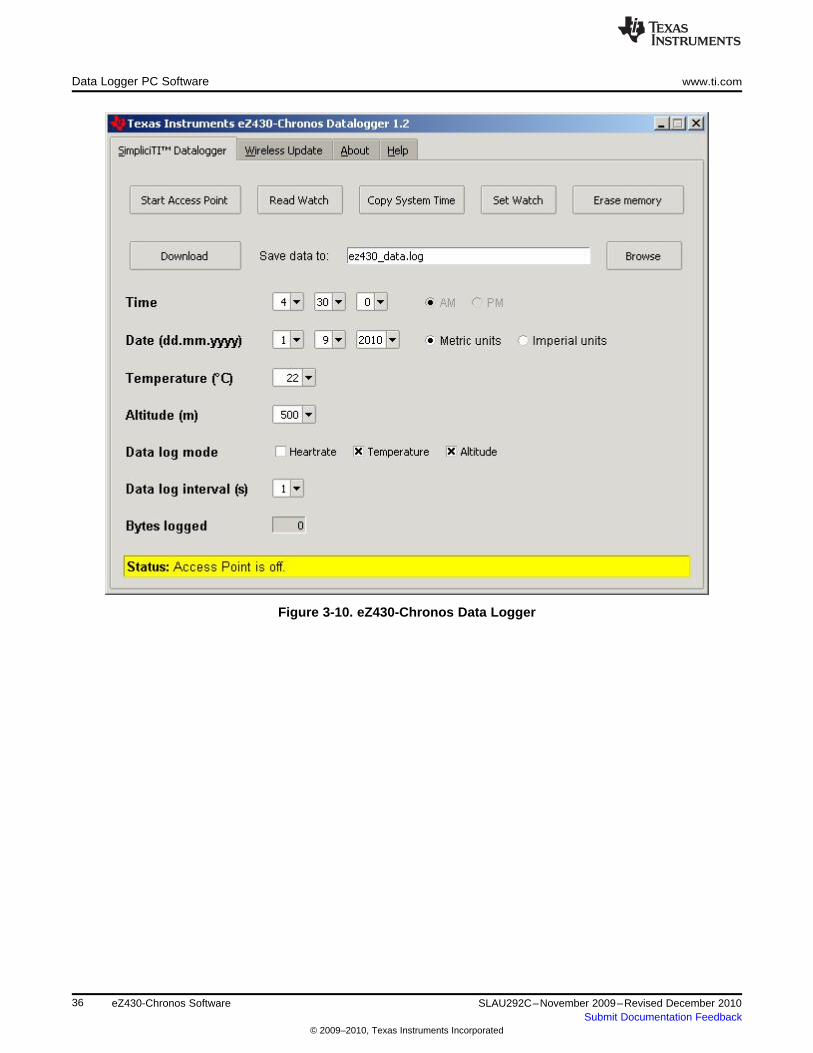
3.5.1 SimpliciTI Data Logger
The SimpliciTI Sync tab offers the possibility setting time/date of the watch including calibration databesides reading out logged data.
Pairing watch and PC:1. Activate the pairing on the PC by clicking on "Start Access Point". The eZ430-Chronos Data Logger
status line displays "Access point started. Now start watch in acc, ppt or sync mode" when the PC isready
2. Select "SYnC" on the eZ430-Chronos watch by pushing the "#" button (see detailed description inSection 3.3.3).
3. Initiate pairing on the watch by pushing the "DOWN" button to activate the selected mode. After a shorttime, the link is established
Setting the watch:1. Select metric or imperial units.2. Enter calibration data for the temperature and altitude OR read back the data from the watch by
clicking on "Read Watch"3. Specify, which data should be logged4. Define logging time interval (1 to 255 seconds), in which data is stored5. Click "Copy System Time" to set watch according to read the PC's system time6. Click "Set Watch" to transfer data to watch7. The watch shows "DONE"8. Push the "DOWN" button on watch to end connection
Reading out logged data:1. Pair watch with PC in case not linked yet - see Pairing watch and PC above2. Specify file name and location of log file3. Click on "Download" to start data transfer4. Push the "DOWN" button to stop connection when the transfer has finished.
The log file is stored in CSV format. Its content appears as one line per log. Each line starts with date,time, heart rate, temperature, and altitude. Parameters which were not logged are set to zero (accordingto settings in eZ430-Chronos Data Logger PC software).
35SLAU292C–November 2009–Revised December 2010 eZ430-Chronos SoftwareSubmit Documentation Feedback
© 2009–2010, Texas Instruments Incorporated
Data Logger PC Software www.ti.com
Figure 3-10. eZ430-Chronos Data Logger
36 eZ430-Chronos Software SLAU292C–November 2009–Revised December 2010Submit Documentation Feedback
© 2009–2010, Texas Instruments Incorporated
www.ti.com Data Logger PC Software
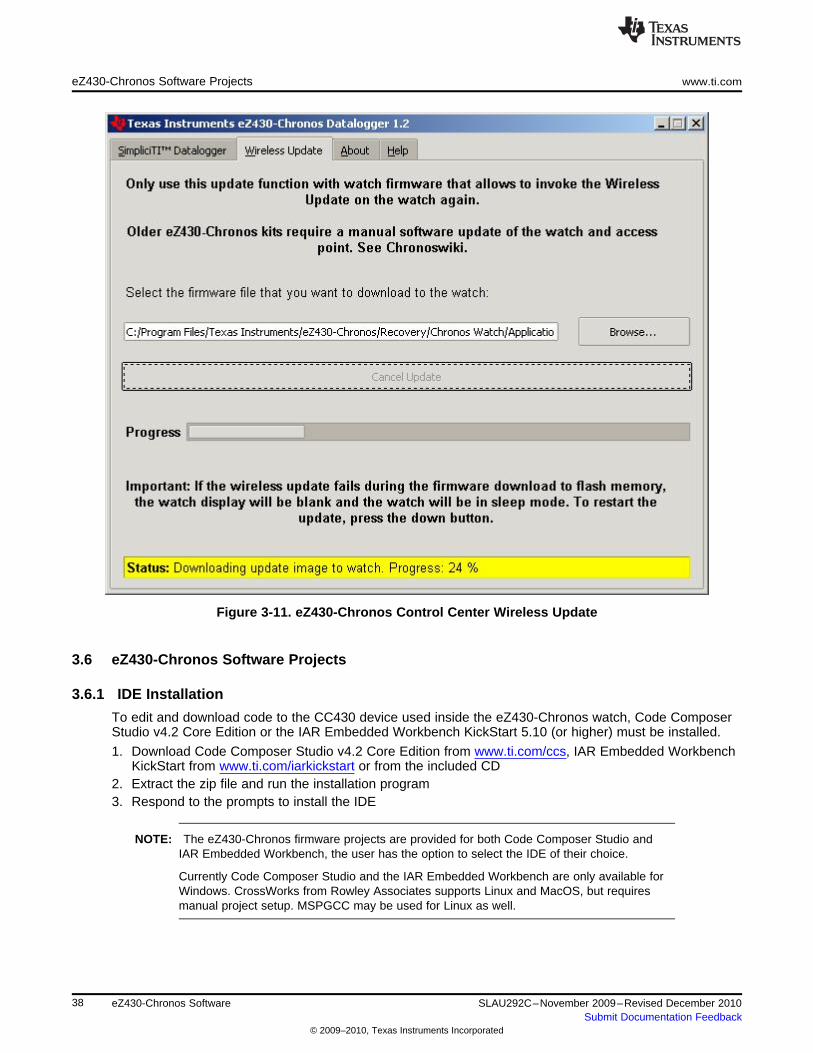
3.5.2 Wireless Update
This mode allows updating the firmware of the eZ430-Chronos watch wirelessly, without having todisassemble the watch.
Update procedure:1. Select CC430 flash image (.txt file) by clicking on "Browse...". Example images for the sports watch
software and the data logger application are located for Windows in C:\Program Files\TexasInstruments\eZ430-Chronos\Recovery\eZ430-Chronos Watch\Applications and for Linux in/home/<user name>/Texas Instruments/eZ430-Chronos/Recovery/eZ430-Chronos Watch/Applications.
NOTE: Ensure selecting the correct version of the flash images. If the wrong frequency is selected,no wireless communication is possible anymore. In that case, the watch must be updatedusing the eZ430 debug interface.
Only transfer flash images to the watch, which allow invoking the updater software on thewatch.
The file to be downloaded to the watch must be in TI-TXT format to work with this updateprocedure. This new firmware must reside within the main memory flash (0x8000 to0xFFFF), otherwise the update procedure fails due to boundary checks on the watch side.
2. Activate the update mechanism on the PC by clicking on "Update eZ430-Chronos Watch". The ControlCenter status line displays "Access point started. Now start watch in rFbSL mode" when the PC isready.
3. Select "rFbSL" on the eZ430-Chronos watch by pushing the "#" button4. Push once "DOWN" button to switch to confirmation menu5. Push "DOWN" again to initiate update6. After a short moment, the update is started
At the beginning of the update the LCD shows "rAM" for a few seconds. During this time, the actualupdater software is downloaded from the PC to the RAM of the CC430 on the watch. This programcontains all memory write and LCD routines. Once this transfer was finished, the code is executedfrom RAM. At this point, the download of the actual firmware file is started. The LCD shows theprogress in percent on the upper LCD line. Once the transfer was complete successfully, a reset startsthe software on the watch. See Section 3.6.3 for details.
NOTE: If the update fails, it can be activated again by pushing the "DOWN" button again on theeZ430-Chronos watch, given that the wireless update is active in the eZ430-Chronos ControlCenter.
37SLAU292C–November 2009–Revised December 2010 eZ430-Chronos SoftwareSubmit Documentation Feedback
© 2009–2010, Texas Instruments Incorporated
eZ430-Chronos Software Projects www.ti.com
Figure 3-11. eZ430-Chronos Control Center Wireless Update
3.6 eZ430-Chronos Software Projects
3.6.1 IDE Installation
To edit and download code to the CC430 device used inside the eZ430-Chronos watch, Code ComposerStudio v4.2 Core Edition or the IAR Embedded Workbench KickStart 5.10 (or higher) must be installed.
1. Download Code Composer Studio v4.2 Core Edition from www.ti.com/ccs, IAR Embedded WorkbenchKickStart from www.ti.com/iarkickstart or from the included CD
2. Extract the zip file and run the installation program3. Respond to the prompts to install the IDE
NOTE: The eZ430-Chronos firmware projects are provided for both Code Composer Studio andIAR Embedded Workbench, the user has the option to select the IDE of their choice.
Currently Code Composer Studio and the IAR Embedded Workbench are only available forWindows. CrossWorks from Rowley Associates supports Linux and MacOS, but requiresmanual project setup. MSPGCC may be used for Linux as well.
38 eZ430-Chronos Software SLAU292C–November 2009–Revised December 2010Submit Documentation Feedback
© 2009–2010, Texas Instruments Incorporated
www.ti.com eZ430-Chronos Software Projects
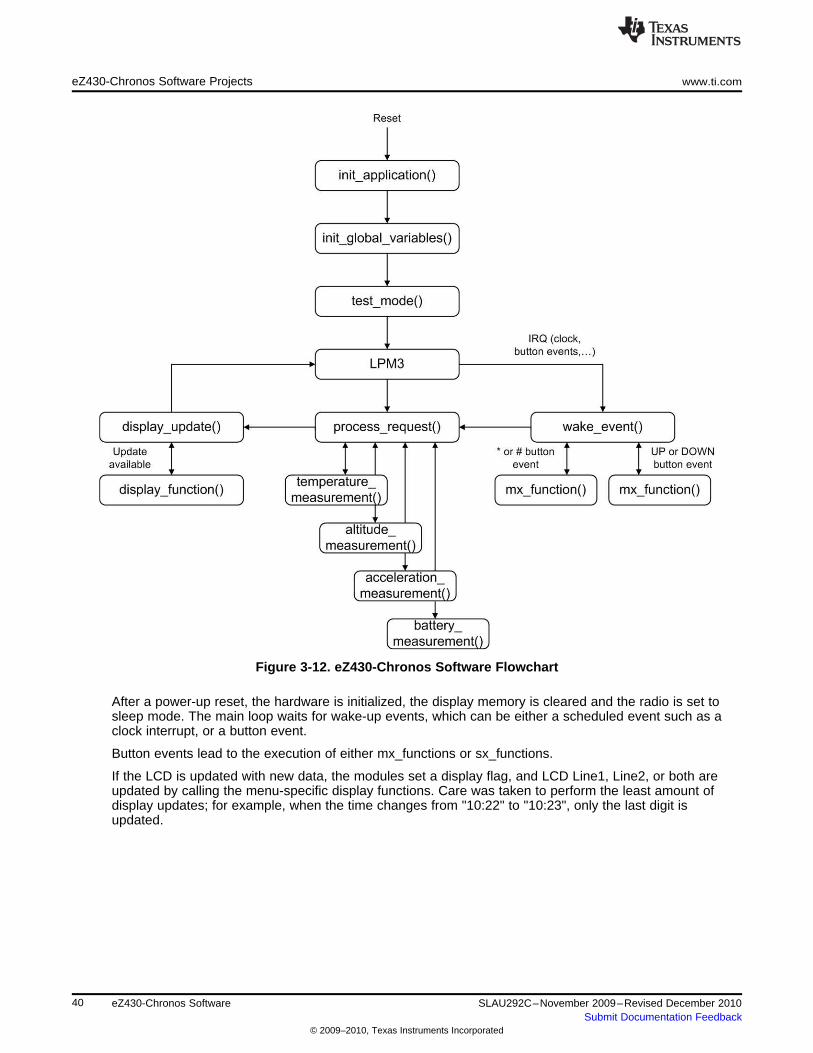
3.6.2 eZ430-Chronos Watch Software Flow
The watch software is structured according to the menu items. The source for each menu item is stored ina separate source file (for example, "temperate.c" for the temperature menu and its functions). Details canbe found in the flow chart below. The data logger application works in a very similar way and therefore isnot described separately.
Each menu item has at least the following functions:
• "UP" or "DOWN" button pushed• "*" or "#" button is pressed for more than 3 seconds
The source code file "menu.c" contains two linked lists with menu items, one for the upper (Line1), one forthe lower LCD line (Line2). Each list entry contains the following pointers
• Pointer to next menu item• "UP" or "DOWN" button is pressed• "*" or "#" button is pressed for more than 3 seconds
To support the various RF frequencies and compiler licenses, the following configurations are available:
RF Frequencies• 915 MHz (USA)• 868 MHz (Europe)• 433 MHz (Other regions)
IDE Versions (CCS, IAR)• Unrestricted IDE versions• Free IDE versions (CCS Core Edition, IAR KickStart). To allow recompilation of the source code, parts
of the source code files have been embedded in libraries; for example, the SimpliciTI stack and most ofthe hardware drivers.
Figure 3-12 shows the basic software flow of the sports watch application.
39SLAU292C–November 2009–Revised December 2010 eZ430-Chronos SoftwareSubmit Documentation Feedback
© 2009–2010, Texas Instruments Incorporated
eZ430-Chronos Software Projects www.ti.com
Figure 3-12. eZ430-Chronos Software Flowchart
After a power-up reset, the hardware is initialized, the display memory is cleared and the radio is set tosleep mode. The main loop waits for wake-up events, which can be either a scheduled event such as aclock interrupt, or a button event.
Button events lead to the execution of either mx_functions or sx_functions.
If the LCD is updated with new data, the modules set a display flag, and LCD Line1, Line2, or both areupdated by calling the menu-specific display functions. Care was taken to perform the least amount ofdisplay updates; for example, when the time changes from "10:22" to "10:23", only the last digit isupdated.
40 eZ430-Chronos Software SLAU292C–November 2009–Revised December 2010Submit Documentation Feedback
© 2009–2010, Texas Instruments Incorporated
www.ti.com eZ430-Chronos Software Projects
3.6.3 eZ430-Chronos Wireless Update Feature
The wireless update feature allows to perform a firmware update of the eZ430-Chronos watch wirelessly,i.e. the watch does not need to be opened. The wireless updater should be seen as an application and notas an universal BSL. It can only be invoked by the main application, which needs to be created in acertain way (see Section 3.6.3.2). In addition it may must be modified to comply local RF regulatory. Thecurrent consumption during the update process may be significant. Considering the small battery capacity,the updater is intended to be used occasionally only.
NOTE: References in the software projects and the menu items of the watch refer to it as "RF BSL"and "WBSL" for simplicity reasons.
Whenever the wireless update is activated on the watch, it returns to the main applicationwith a reset, regardless if an update was performed or not. Time, data, alarm and other RAMbased data are lost.
3.6.3.1 Overview and Components of the Wireless Update Feature
As described in the previous section, the wireless update feature allows updating the eZ430-Chronosfirmware wirelessly. One of the requirements for the wireless update was to spend as little flash memoryas possible. Therefore, the lightweight radio protocol was developed, which resides in the BSL Flash areaof the CC430. The software part handing the LCD progress information and the Flash memoryprogramming is download over the air and executed in RAM. Components of the wireless updater:
• Radio protocol in BSL memory area of the CC430 (eZ430-Chronos watch module)• The "RAM based updater" contains LCD and Flash write routines (transferred from PC to RAM of
watch module)• Radio protocol stack of the wireless update on RF access point (CC1111)• PC application supporting the update functionality
The update procedure works as follows:
1. Wireless update functionality was activated in PC application, after a valid flash image was selected2. RF access point ready - awaits request from watch3. Wireless update is activated on watch4. Watch downloads LCD and flash write routines (RAM based updater) from the PC into RAM of CC430.
Watch shows "rAN" (=RAM).5. Watch executes the RAM based updater. This starts the actual code (flash image) download process.
The LCD shows the progress.6. A reset starts the new application on the watch when the update is finished.
The FAQ in Appendix A also list common questions on the wireless update Feature.
3.6.3.2 Detailed Description of the Wireless Update Feature
To invoke the wireless update procedure, the main application must call the start of the wireless updater,which is located at address 0x1000. Therefore, the sports watch and data logger projects contain an extramenu item called "rFbSL". Once activated, it checks if the battery level of the watch is sufficient to start awireless update and then calls address 0x1000. At this point the user application is no longer running.
NOTE: Whenever the wireless update is activated on the watch, it returns to the main applicationwith a reset, regardless if an update was performed or not. Time, data, alarm and otherRAM-based data is lost.
41SLAU292C–November 2009–Revised December 2010 eZ430-Chronos SoftwareSubmit Documentation Feedback
© 2009–2010, Texas Instruments Incorporated
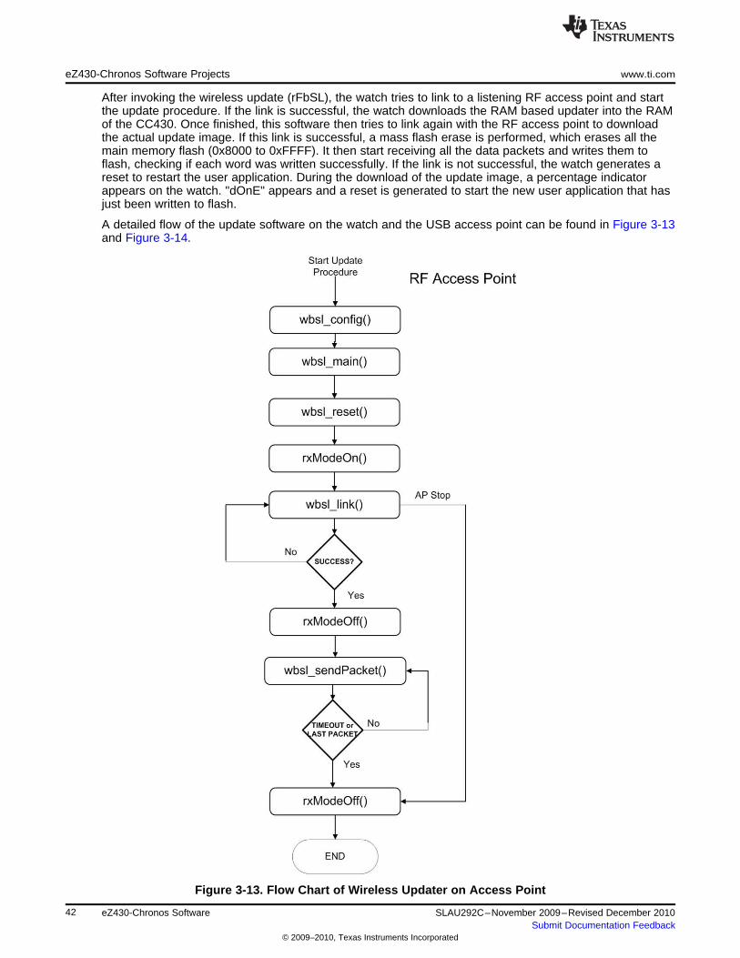
eZ430-Chronos Software Projects www.ti.com
After invoking the wireless update (rFbSL), the watch tries to link to a listening RF access point and startthe update procedure. If the link is successful, the watch downloads the RAM based updater into the RAMof the CC430. Once finished, this software then tries to link again with the RF access point to downloadthe actual update image. If this link is successful, a mass flash erase is performed, which erases all themain memory flash (0x8000 to 0xFFFF). It then start receiving all the data packets and writes them toflash, checking if each word was written successfully. If the link is not successful, the watch generates areset to restart the user application. During the download of the update image, a percentage indicatorappears on the watch. "dOnE" appears and a reset is generated to start the new user application that hasjust been written to flash.
A detailed flow of the update software on the watch and the USB access point can be found in Figure 3-13and Figure 3-14.
Figure 3-13. Flow Chart of Wireless Updater on Access Point
42 eZ430-Chronos Software SLAU292C–November 2009–Revised December 2010Submit Documentation Feedback
© 2009–2010, Texas Instruments Incorporated

www.ti.com eZ430-Chronos Software Projects
Figure 3-14. Flow Chart of Flash Based Wireless Updater on eZ430-Chronos Watch Module
43SLAU292C–November 2009–Revised December 2010 eZ430-Chronos SoftwareSubmit Documentation Feedback
© 2009–2010, Texas Instruments Incorporated
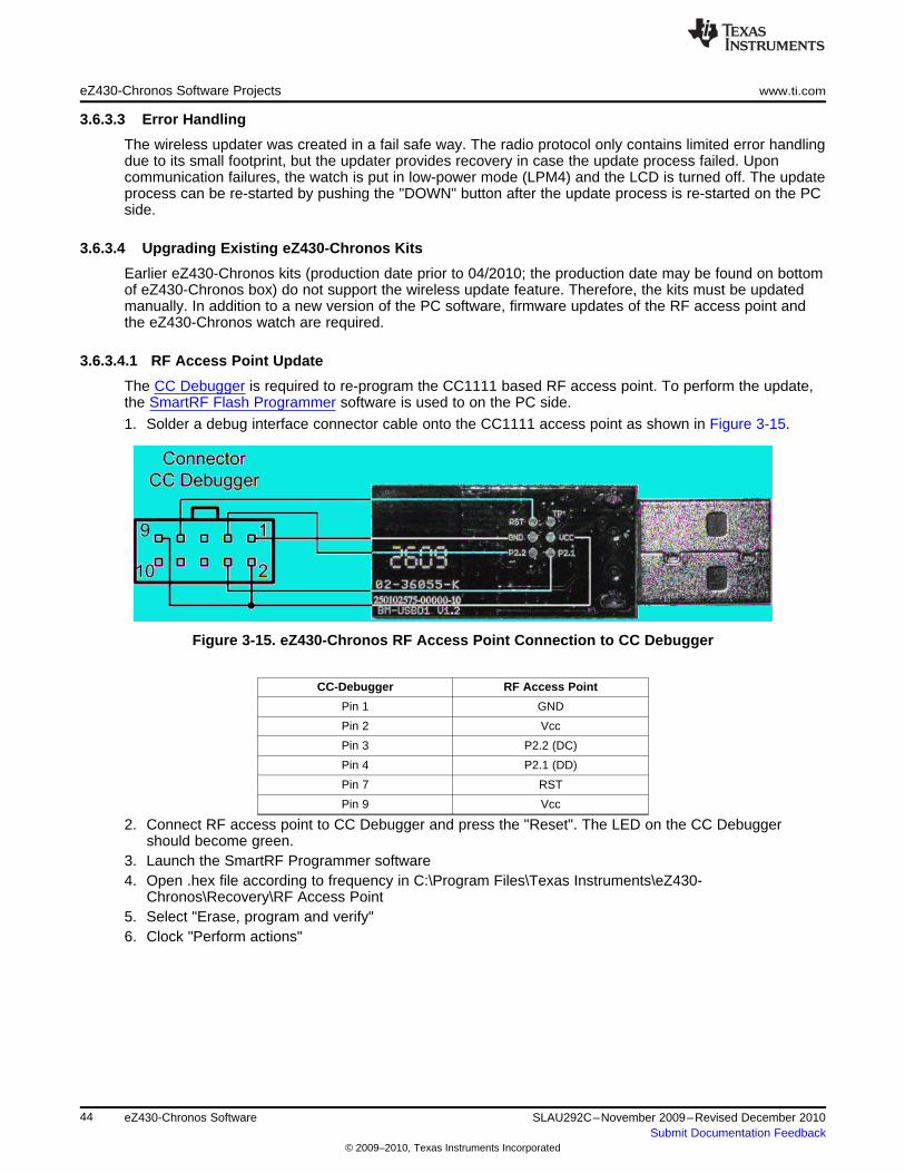
eZ430-Chronos Software Projects www.ti.com
3.6.3.3 Error Handling
The wireless updater was created in a fail safe way. The radio protocol only contains limited error handlingdue to its small footprint, but the updater provides recovery in case the update process failed. Uponcommunication failures, the watch is put in low-power mode (LPM4) and the LCD is turned off. The updateprocess can be re-started by pushing the "DOWN" button after the update process is re-started on the PCside.
3.6.3.4 Upgrading Existing eZ430-Chronos Kits
Earlier eZ430-Chronos kits (production date prior to 04/2010; the production date may be found on bottomof eZ430-Chronos box) do not support the wireless update feature. Therefore, the kits must be updatedmanually. In addition to a new version of the PC software, firmware updates of the RF access point andthe eZ430-Chronos watch are required.
3.6.3.4.1 RF Access Point Update
The CC Debugger is required to re-program the CC1111 based RF access point. To perform the update,the SmartRF Flash Programmer software is used to on the PC side.
1. Solder a debug interface connector cable onto the CC1111 access point as shown in Figure 3-15.
Figure 3-15. eZ430-Chronos RF Access Point Connection to CC Debugger
CC-Debugger RF Access Point
Pin 1 GND
Pin 2 Vcc
Pin 3 P2.2 (DC)
Pin 4 P2.1 (DD)
Pin 7 RST
Pin 9 Vcc
2. Connect RF access point to CC Debugger and press the "Reset". The LED on the CC Debuggershould become green.
3. Launch the SmartRF Programmer software4. Open .hex file according to frequency in C:\Program Files\Texas Instruments\eZ430-
Chronos\Recovery\RF Access Point5. Select "Erase, program and verify"6. Clock "Perform actions"
44 eZ430-Chronos Software SLAU292C–November 2009–Revised December 2010Submit Documentation Feedback
© 2009–2010, Texas Instruments Incorporated
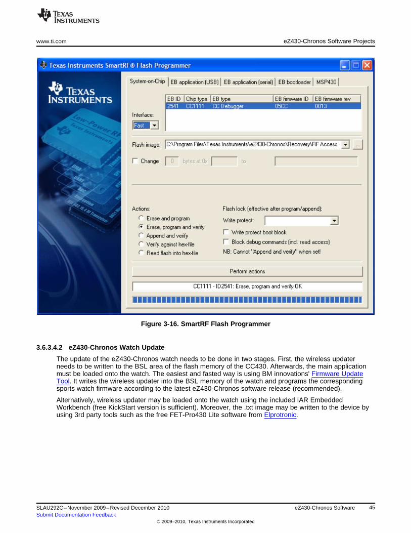
www.ti.com eZ430-Chronos Software Projects
Figure 3-16. SmartRF Flash Programmer
3.6.3.4.2 eZ430-Chronos Watch Update
The update of the eZ430-Chronos watch needs to be done in two stages. First, the wireless updaterneeds to be written to the BSL area of the flash memory of the CC430. Afterwards, the main applicationmust be loaded onto the watch. The easiest and fasted way is using BM innovations' Firmware UpdateTool. It writes the wireless updater into the BSL memory of the watch and programs the correspondingsports watch firmware according to the latest eZ430-Chronos software release (recommended).
Alternatively, wireless updater may be loaded onto the watch using the included IAR EmbeddedWorkbench (free KickStart version is sufficient). Moreover, the .txt image may be written to the device byusing 3rd party tools such as the free FET-Pro430 Lite software from Elprotronic.
45SLAU292C–November 2009–Revised December 2010 eZ430-Chronos SoftwareSubmit Documentation Feedback
© 2009–2010, Texas Instruments Incorporated
eZ430-Chronos Software Projects www.ti.com
3.6.3.4.2.1 eZ430-Chronos Watch Update Using IAR
The project is available in C:\Program Files\Texas Instruments\eZ430-Chronos\Software Projects\eZ430-Chronos Watch\IAR\Wireless Update. The eZ430-Chronos watch module needs to be connected to theemulator which must be connected to the PC.
1. Open project by double clicking "Wireless Updater.eww"2. Select build configuration according to frequency in Project > Edit Configurations...3. Click Project > Download and Debug4. Close the Embedded Workbench after code was written5. Program watch main application as described in Section 3.6.4.
3.6.4 eZ430-Chronos Firmware
To restore or modify the original watch projects, the source code must be installed. This happens duringthe installation of the demo software package (SLAC341), which contains two different sets of examples.Code Composer Studio v4.2 or the IAR Workbench can be used, regardless if code limited or not.
3.6.4.1 Using Code Composer Studio™ v4.21. Launch Code Composer Studio v4.2: Start > All Programs > Texas Instruments > Code Composer
Studio v4 > Code Composer Studio v42. Create new Workspace or open existing Workspace that does not yet contain eZ430-Chronos projects
NOTE: Workspaces should not be located in a long path of directories as Windows only supportspath names up to 255 characters. Keep in mind that the projects contain subdirectories aswell.
3. Import eZ430-Chronos Projects by clicking: Project > Import Existing CCE/CCS Eclipse Project4. Click Browse and browse to eZ430-Chronos Projects (default directory: C:\Program Files\Texas
Instruments\eZ430-Chronos\Software Projects\eZ430-Chronos Watch\CCS). Confirm directory byclicking OK
5. The eZ430-Chronos sports watch project appears as ez430_chronos, the eZ430-Chronos data loggerappears as ez430_chronos_datalogger. Select Copy projects into workspace to create a new copy ofthe projects
6. Click Finish to finalize the project import. The projects appear in the C/C++ Projects view of CCS7. Select the right version of the project. Each project comes with six different project settings (build
configurations), which can be selected in Project > Properties > C/C++ Build > Active Configuration >Configuration:915 MHz – Limited CCS Core Edition (USA)868 MHz – Limited CCS Core Edition (Europe)433 MHz – Limited CCS Core Edition (Other regions)915 MHz – Unrestricted CCS Platinum (USA)868 MHz – Unrestricted CCS Platinum (Europe)433 MHz – Unrestricted CCS Platinum (Other regions)
8. Go to Target > Debug Active > Debug Active Project to launch the debugger
46 eZ430-Chronos Software SLAU292C–November 2009–Revised December 2010Submit Documentation Feedback
© 2009–2010, Texas Instruments Incorporated
www.ti.com eZ430-Chronos Software Projects
3.6.4.2 Using IAR Embedded Workbench™1. Launch the Embedded Workbench:Start > All Programs > IAR Systems > IAR Embedded Workbench
KickStart for MSP430 5.10 > IAR Embedded Workbench2. Open eZ430-Chronos Workspace by: File > Open > Workspace...3. Browse to eZ430-Chronos Projects (default directory: C:\Program Files\Texas Instruments\eZ430-
Chronos\Software Projects\IAR\eZ430-Chronos Watch\Sports Watch or C:\Program Files\TexasInstruments\eZ430-Chronos\Software Projects\IAR\eZ430-Chronos Watch\Data Logger)
4. Select *.eww file and click Open5. Select the right version of the project. Each project comes with four different project settings (build
configurations), which can be selected on top of the Workspace window:915 MHz – Limited IAR KickStart (USA)868 MHz – Limited IAR KickStart (Europe)433 MHz – Limited IAR KickStart (Other regions)915 MHz – Unrestricted IAR Workbench (USA)868 MHz – Unrestricted IAR Workbench (Europe)433 MHz – Unrestricted IAR Workbench (Other regions)
6. Go to Project > Download and Debug to launch the debugger
3.6.5 eZ430-Chronos GUI Sources
Full sources of the eZ430-Chronos Control Center and eZ430-Chronos Data Logger are available in theeZ430-Chronos software packages for Windows SLAC341 and Linux SLAC388. The sources are copiedto your system during the software installation. The graphical user interfaces are based on TCL/Tk.
3.6.5.1 eZ430-Chronos GUI for Windows
The eZ430-Chronos PC software consists of a TCL/Tk executable and a DLL, which handles thecommunication with the RF access Point. Download TCL/Tk for Windows for free fromhttp://www.activestate.com/activetcl. Once TCL/Tk was installed on the computer, a double-click on a TCLscript (*.tcl) starts the interpreter and executes the script. Alternatively, start the TCL interpreter wish.exeand execute the script with the "source" command. If the script filename contains blanks, put it into quotes.The sources files are located in C:\Program Files\Texas Instruments\eZ430-Chronos\Control Center\GUISources
3.6.5.1.1 TCL/TK Handling
A wrapping tool is needed to compile all TCL/Tk components into standalone applications. The freewaretool Freewrap http://freewrap.sourceforge.net may be used for that purpose.
1. Open Command Prompt2. Navigate to the Freewrap directory; for example, C:\Tcl\freewrap3. Start Freewrap with the complete path to the TCL script to be wrapped; for example, freewrap.exe
C:\Program Files\Texas Instruments\eZ430-Chronos\Control Center\eZ430-Chronos ControlCenter\eZ430-Chronos CC 1_2.tcl
A standalone application, which only requires the corresponding Windows DLL is generated. It can beused on every PC, TCL/Tk must not be installed.
47SLAU292C–November 2009–Revised December 2010 eZ430-Chronos SoftwareSubmit Documentation Feedback
© 2009–2010, Texas Instruments Incorporated
eZ430-Chronos Software Projects www.ti.com
3.6.5.1.2 Control Center DLL
The sources for the DLL are available in the eZ430-Chronos Windows package and can be found inC:\Program Files\Texas Instruments\eZ430-Chronos\Control Center\GUI Sources\DLL.
The eZ430-Chronos Windows DLL has been developed using Microsoft Visual C++ 2008 Express Edition.In order to rebuild the DLL file the Microsoft Visual Studio must be installed, since the registry enumerationcode uses MFC functions. If Microsoft Visual Studio is not present, it is still possible to rebuild the DLL, butthe "enumser" source code part needs to be removed from the project. Therefore, the BM_GetCOM()function won’t work anymore.
The DLL has two interface sections, one that exports standard C functions, and a second one exportingTCL-compliant functions. These TCL-compliant functions are used by the graphical user interface. Hence,when compiling the DLL, TCL needs to be present in the default directory (C:\Tcl); otherwise, thereference to the TCL libraries (tcl85.lib, tclstub85.lib) is invalid. If the DLL is compiled without the TCLinterface, the respective source code file and the references to the TCL libraries must be deleted.
COM Port Management1. Opening the COM port
Prior to any communication, the COM port where the RF access point is connected must be opened.The hardware is powered up immediately after the unit is connected. Some parts of the hardwarerequire a startup time of several hundred milliseconds. As a result, any access to the hardware shouldnot be done within one second after connecting the device.
NOTE: To address COM ports higher than COM9 in Windows, precede the "COMxx" string with thesequence "\\.\".
The COM port is opened with the following function:bool BM_OpenCOM( char * strPortName,
DWORD dwBaudrate = 115200,WORD wTimeout = 30,bool bRTS = false,bool bDTR = false);
ParametersstrPortName
Name of the COM port (for example, "\\.\COM11").wTimeout
Time in milliseconds a reply to a command is expected; default value is 30 ms, should not bechanged
dwBaudrateBaudrate for the serial interface; default is 115200 Baud, should not be changed
bRTSState of RTS line during normal operation; default is false (=GND), should not be changed
bDTRState of DTR line during normal operation; default is false (=GND), should not be changed
Return ValueReturns true if COM port could be opened, otherwise returns false.
2. Closing the COM portA successfully opened COM port must be closed when quitting the application to release all allocatedmemory and the port itself.The COM port is closed with the following function:void BM_CloseCOM(void);
48 eZ430-Chronos Software SLAU292C–November 2009–Revised December 2010Submit Documentation Feedback
© 2009–2010, Texas Instruments Incorporated
www.ti.com eZ430-Chronos Software Projects
3. Locating the RF access pointThis function checks the Windows registry for the friendly name "TI CC1111 Low-Power RF to USBCDC Serial Port" and returns the COM port number if the device was found.bool BM_GetCOM(unsigned char& bPortNb);
ParametersbPortNb
Number of the COM port (for example, „11")Return Value
Returns true if device was found, otherwise returns false.4. Resetting the RF access point
After power-up, the hardware is not automatically reset. Use the following function to initialize the RFaccess point hardware. This function can also be used during normal operation if an error conditionwas detected.bool BM_Reset(void);
Return ValueReturns true if RF access point could be initialized successfully and false if the reset failed.
5. Read status from RF access pointThis command returns the current RF access point status.bool BM_GetStatus(WORD& wStatus);
ParameterswStatus
Current status of RF access point HW_IDLE, HW_SIMPLICITI_STOPPED,HW_SIMPLICITI_TRYING_TO_LINK, HW_SIMPLICITI_LINKED, HW_BLUEROBIN_STOPPED,HW_BLUEROBIN_TRANSMITTING, HW_ERROR, HW_NO_ERROR, HW_NOT_CONNECTED
Return ValueReturns true if command could be executed and false if the command execution failed.
BlueRobin Functions1. Set BlueRobin Heart Rate
This command sets the heart rate value that is transmitted in each BlueRobin packet.bool BM_BR_SetHeartrate(WORD wHeartrate);
ParameterswHeartrate
Heart rate in bpmReturn Value
Returns true if command could be executed and false if the command execution failed.2. Set BlueRobin ID
This command sets the transmitter ID for BlueRobin transmission.bool BM_BR_SetID(DWORD dwID);
ParametersdwID
24-bit transmitter IDReturn Value
Returns true if command could be executed and false if the command execution failed.
49SLAU292C–November 2009–Revised December 2010 eZ430-Chronos SoftwareSubmit Documentation Feedback
© 2009–2010, Texas Instruments Incorporated
eZ430-Chronos Software Projects www.ti.com
3. Read BlueRobin IDThis command reads the transmitter ID for BlueRobin transmission.bool BM_BR_GetID(DWORD& dwID);
ParametersdwID
24-bit transmitter IDReturn Value
Returns true if command could be executed and false if the command execution failed.4. Start BlueRobin transmission
This command starts the BlueRobin transmission.bool BM_BR_Start(void);
Return ValueReturns true if command could be executed and false if the command execution failed.
5. Stop BlueRobin transmissionThis command stops the BlueRobin transmission.bool BM_BR_Stop(void);
Return ValueReturns true if command could be executed and false if the command execution failed.
SimpliciTI Functions1. Start SimpliciTI in acc/ppt mode
This command starts SimpliciTI in acc/ppt mode.bool BM_SPL_Start(void);
Return ValueReturns true if command could be executed and false if the command execution failed.
2. Start SimpliciTI in sync modeThis command starts SimpliciTI in sync mode.bool BM_SYNC_Start(void);
Return ValueReturns true if command could be executed and false if the command execution failed.
3. Stop SimpliciTIThis command exits the SimpliciTI stack.bool BM_SPL_Stop(void);
Return ValueReturns true if command could be executed and false if the command execution failed.
50 eZ430-Chronos Software SLAU292C–November 2009–Revised December 2010Submit Documentation Feedback
© 2009–2010, Texas Instruments Incorporated
www.ti.com eZ430-Chronos Software Projects
4. Read SimpliciTI acc/ppt dataThis command reads the received data from the RF access point buffer.bool BM_SPL_GetData(DWORD& wData);
ParameterswData
4 byte data (byte3, byte2, byte1, byte0)byte3 = Acceleration value Z-axisbyte2 = Acceleration value Y-axisbyte1 = Acceleration value X-axisbyte0 = 0x11 → Left mouse click (acc mode)byte0 = 0x21 → Left mouse double-click (acc mode)byte0 = 0x31 → Right mouse click (acc mode)byte0 = 0x12 → Button * (ppt mode)byte0 = 0x22 → Button # (ppt mode)byte0 = 0x32 → Button ↑ (ppt mode)byte0 = 0xFF → Data has been read before
Return ValueReturns true if command could be executed and false if the command execution failed.
5. Read SimpliciTI sync buffer statusThis command reads the buffer status during sync mode from the RF access point buffer.bool BM_SYNC_GetBufferStatus(WORD& wStatus);
ParameterswStatus
Buffer status0 = Buffer empty1 = Data available for download
Return ValueReturns true if command could be executed and false if the command execution failed.
6. Read SimpliciTI sync bufferThis command reads the buffer content during sync mode.bool BM_SYNC_ReadBuffer(BYTE * bData);
ParametersbData
19-byte SimpliciTI data Packet content defined watch sending routineReturn Value
Returns true if command could be executed and false if the command execution failed.
Wireless Update Functions1. Start wireless update
This command starts SimpliciTI in acc/ppt mode.BR_COMM_API bool BM_WBSL_Start(void)
Return ValueReturns true if command could be executed and false if the command execution failed.
2. Stop wireless updateThis command exits the SimpliciTI stack.BR_COMM_API bool BM_WBSL_Stop(void)
Return ValueReturns true if command could be executed and false if the command execution failed.
51SLAU292C–November 2009–Revised December 2010 eZ430-Chronos SoftwareSubmit Documentation Feedback
© 2009–2010, Texas Instruments Incorporated
eZ430-Chronos Software Projects www.ti.com
3. Get status of updateThis command reads the buffer status during sync mode from the RF access point buffer.BR_COMM_API bool BM_WBSL_GetStatus(DWORD& wData)
ParametersdwData
Status1 = linking2 = linked4 = error
Return ValueReturns true if command could be executed and false if the command execution failed.
4. Send Data (Text File parts) to the End DeviceThis command reads the buffer status during sync mode from the RF access point buffer.BR_COMM_API bool BM_WBSL_Send_Data(BYTE * data, int len, DWORD& dwData)
Parametersdata
Pointer to byte arraylen
Array lengthdwData
Return valueReturn Value
dwData = Length of last transmitted package.5. Get status of packet (checks if a new packet needs to be sent from the GUI)
This command reads the buffer status during sync mode from the RF access point buffer.BR_COMM_API bool BM_WBSL_GetPacketStatus(DWORD& wData)
Return ValuedwData
0x80 = error0x01 = disabled0x02 = processing packet0x04 = send info packet0x08 = send new data packet
3.6.5.2 eZ430-Chronos GUI for Linux
The eZ430-Chronos PC software for Linux consists of a TCL/Tk scrips, similar to its Windows equivalent.The scripts are available in/home/<user name>/Texas Instruments/eZ430-Chronos/Control Center/eZ430-Chronos Control Center.
See Section 3.3 for instructions on how to run these scripts on Linux machines.
52 eZ430-Chronos Software SLAU292C–November 2009–Revised December 2010Submit Documentation Feedback
© 2009–2010, Texas Instruments Incorporated
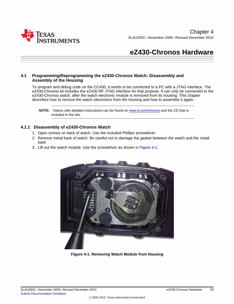
Chapter 4SLAU292C–November 2009–Revised December 2010
eZ430-Chronos Hardware
4.1 Programming/Reprogramming the eZ430-Chronos Watch: Disassembly andAssembly of the Housing
To program and debug code on the CC430, it needs to be connected to a PC with a JTAG interface. TheeZ430-Chronos kit includes the eZ430-RF JTAG interface for that purpose. It can only be connected to theeZ430-Chronos watch, after the watch electronic module is removed from its housing. This chapterdescribes how to remove the watch electronics from the housing and how to assemble it again.
NOTE: Videos with detailed instructions can be found on www.ti.com/chronos and the CD that isincluded in the kits.
4.1.1 Disassembly of eZ430-Chronos Watch1. Open screws on back of watch. Use the included Phillips screwdriver2. Remove metal back of watch. Be careful not to damage the gasket between the watch and the metal
back3. Lift out the watch module. Use the screwdriver as shown in Figure 4-1.
Figure 4-1. Removing Watch Module from Housing
53SLAU292C–November 2009–Revised December 2010 eZ430-Chronos HardwareSubmit Documentation Feedback
© 2009–2010, Texas Instruments Incorporated
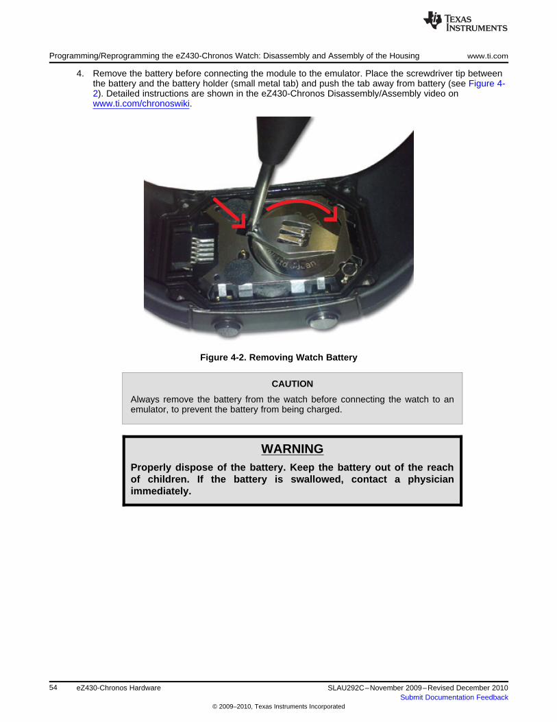
Programming/Reprogramming the eZ430-Chronos Watch: Disassembly and Assembly of the Housing www.ti.com
4. Remove the battery before connecting the module to the emulator. Place the screwdriver tip betweenthe battery and the battery holder (small metal tab) and push the tab away from battery (see Figure 4-2). Detailed instructions are shown in the eZ430-Chronos Disassembly/Assembly video onwww.ti.com/chronoswiki.
Figure 4-2. Removing Watch Battery
CAUTION
Always remove the battery from the watch before connecting the watch to anemulator, to prevent the battery from being charged.
WARNINGProperly dispose of the battery. Keep the battery out of the reachof children. If the battery is swallowed, contact a physicianimmediately.
54 eZ430-Chronos Hardware SLAU292C–November 2009–Revised December 2010Submit Documentation Feedback
© 2009–2010, Texas Instruments Incorporated
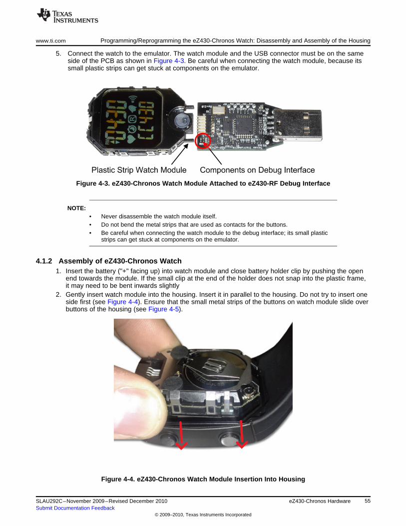
www.ti.com Programming/Reprogramming the eZ430-Chronos Watch: Disassembly and Assembly of the Housing
5. Connect the watch to the emulator. The watch module and the USB connector must be on the sameside of the PCB as shown in Figure 4-3. Be careful when connecting the watch module, because itssmall plastic strips can get stuck at components on the emulator.
Figure 4-3. eZ430-Chronos Watch Module Attached to eZ430-RF Debug Interface
NOTE:• Never disassemble the watch module itself.• Do not bend the metal strips that are used as contacts for the buttons.• Be careful when connecting the watch module to the debug interface; its small plastic
strips can get stuck at components on the emulator.
4.1.2 Assembly of eZ430-Chronos Watch1. Insert the battery ("+" facing up) into watch module and close battery holder clip by pushing the open
end towards the module. If the small clip at the end of the holder does not snap into the plastic frame,it may need to be bent inwards slightly
2. Gently insert watch module into the housing. Insert it in parallel to the housing. Do not try to insert oneside first (see Figure 4-4). Ensure that the small metal strips of the buttons on watch module slide overbuttons of the housing (see Figure 4-5).
Figure 4-4. eZ430-Chronos Watch Module Insertion Into Housing
55SLAU292C–November 2009–Revised December 2010 eZ430-Chronos HardwareSubmit Documentation Feedback
© 2009–2010, Texas Instruments Incorporated
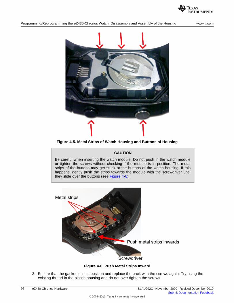
Programming/Reprogramming the eZ430-Chronos Watch: Disassembly and Assembly of the Housing www.ti.com
Figure 4-5. Metal Strips of Watch Housing and Buttons of Housing
CAUTION
Be careful when inserting the watch module. Do not push in the watch moduleor tighten the screws without checking if the module is in position. The metalstrips of the buttons may get stuck at the buttons of the watch housing. If thishappens, gently push the strips towards the module with the screwdriver untilthey slide over the buttons (see Figure 4-6).
Figure 4-6. Push Metal Strips Inward
3. Ensure that the gasket is in its position and replace the back with the screws again. Try using theexisting thread in the plastic housing and do not over tighten the screws.
56 eZ430-Chronos Hardware SLAU292C–November 2009–Revised December 2010Submit Documentation Feedback
© 2009–2010, Texas Instruments Incorporated
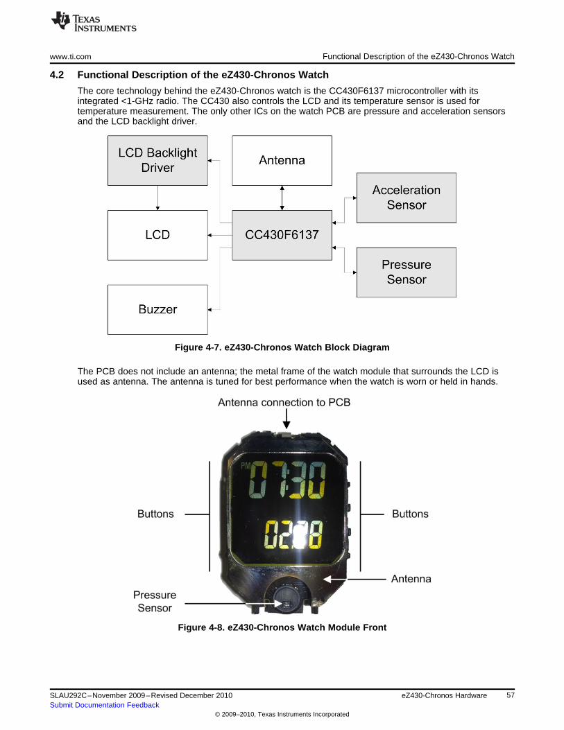
www.ti.com Functional Description of the eZ430-Chronos Watch
4.2 Functional Description of the eZ430-Chronos Watch
The core technology behind the eZ430-Chronos watch is the CC430F6137 microcontroller with itsintegrated <1-GHz radio. The CC430 also controls the LCD and its temperature sensor is used fortemperature measurement. The only other ICs on the watch PCB are pressure and acceleration sensorsand the LCD backlight driver.
Figure 4-7. eZ430-Chronos Watch Block Diagram
The PCB does not include an antenna; the metal frame of the watch module that surrounds the LCD isused as antenna. The antenna is tuned for best performance when the watch is worn or held in hands.
Figure 4-8. eZ430-Chronos Watch Module Front
57SLAU292C–November 2009–Revised December 2010 eZ430-Chronos HardwareSubmit Documentation Feedback
© 2009–2010, Texas Instruments Incorporated
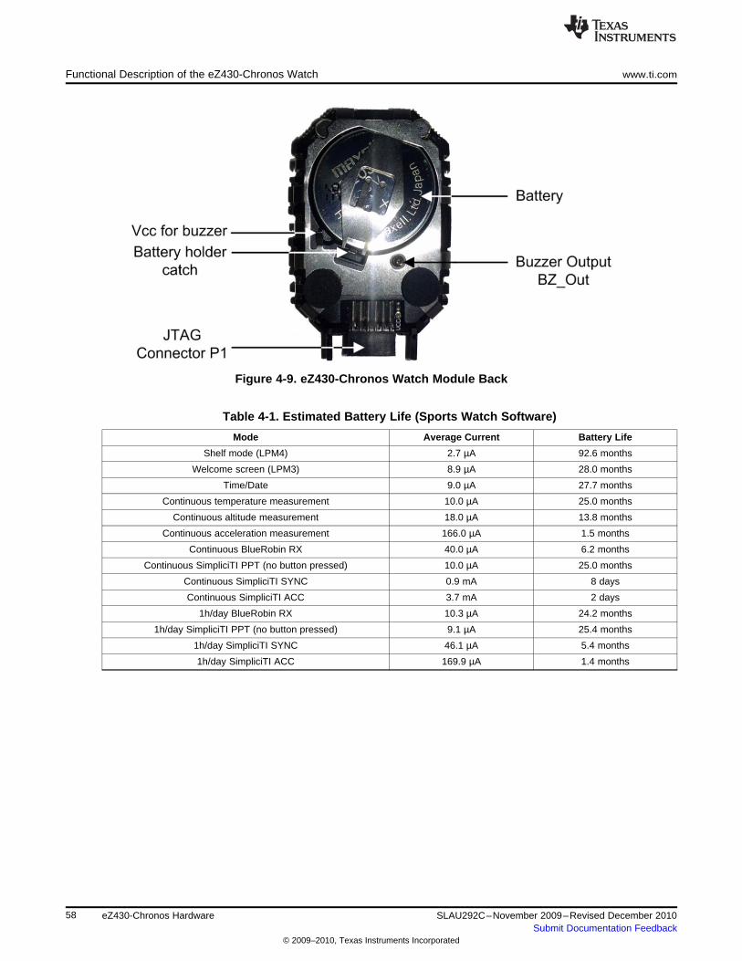
Functional Description of the eZ430-Chronos Watch www.ti.com
Figure 4-9. eZ430-Chronos Watch Module Back
Table 4-1. Estimated Battery Life (Sports Watch Software)
Mode Average Current Battery Life
Shelf mode (LPM4) 2.7 µA 92.6 months
Welcome screen (LPM3) 8.9 µA 28.0 months
Time/Date 9.0 µA 27.7 months
Continuous temperature measurement 10.0 µA 25.0 months
Continuous altitude measurement 18.0 µA 13.8 months
Continuous acceleration measurement 166.0 µA 1.5 months
Continuous BlueRobin RX 40.0 µA 6.2 months
Continuous SimpliciTI PPT (no button pressed) 10.0 µA 25.0 months
Continuous SimpliciTI SYNC 0.9 mA 8 days
Continuous SimpliciTI ACC 3.7 mA 2 days
1h/day BlueRobin RX 10.3 µA 24.2 months
1h/day SimpliciTI PPT (no button pressed) 9.1 µA 25.4 months
1h/day SimpliciTI SYNC 46.1 µA 5.4 months
1h/day SimpliciTI ACC 169.9 µA 1.4 months
58 eZ430-Chronos Hardware SLAU292C–November 2009–Revised December 2010Submit Documentation Feedback
© 2009–2010, Texas Instruments Incorporated
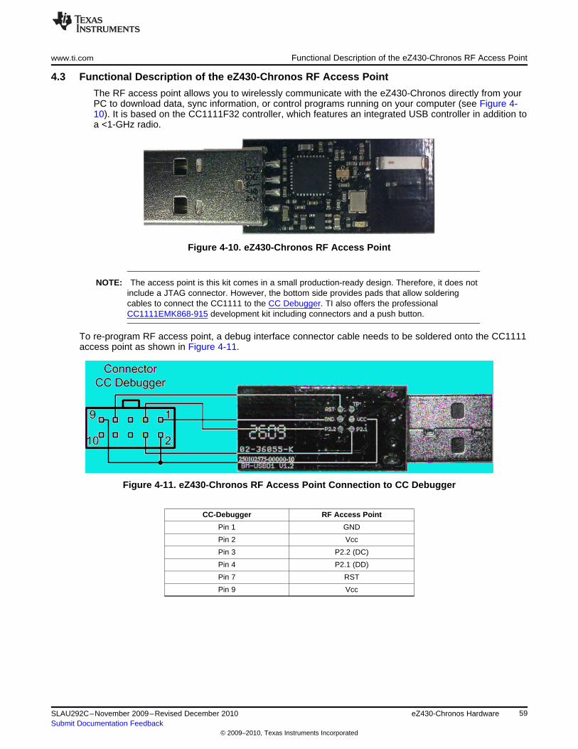
www.ti.com Functional Description of the eZ430-Chronos RF Access Point
4.3 Functional Description of the eZ430-Chronos RF Access Point
The RF access point allows you to wirelessly communicate with the eZ430-Chronos directly from yourPC to download data, sync information, or control programs running on your computer (see Figure 4-10). It is based on the CC1111F32 controller, which features an integrated USB controller in addition toa <1-GHz radio.
Figure 4-10. eZ430-Chronos RF Access Point
NOTE: The access point is this kit comes in a small production-ready design. Therefore, it does notinclude a JTAG connector. However, the bottom side provides pads that allow solderingcables to connect the CC1111 to the CC Debugger. TI also offers the professionalCC1111EMK868-915 development kit including connectors and a push button.
To re-program RF access point, a debug interface connector cable needs to be soldered onto the CC1111access point as shown in Figure 4-11.
Figure 4-11. eZ430-Chronos RF Access Point Connection to CC Debugger
CC-Debugger RF Access Point
Pin 1 GND
Pin 2 Vcc
Pin 3 P2.2 (DC)
Pin 4 P2.1 (DD)
Pin 7 RST
Pin 9 Vcc
59SLAU292C–November 2009–Revised December 2010 eZ430-Chronos HardwareSubmit Documentation Feedback
© 2009–2010, Texas Instruments Incorporated
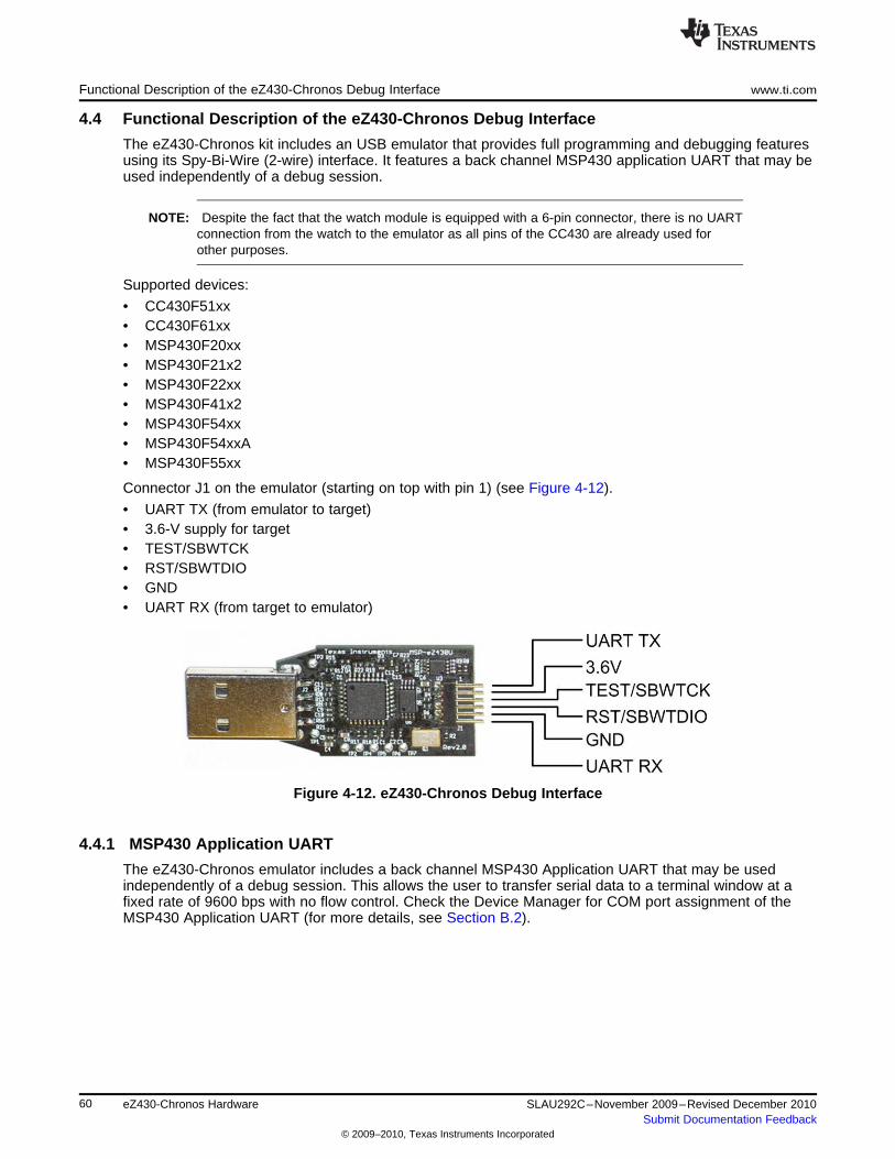
Functional Description of the eZ430-Chronos Debug Interface www.ti.com
4.4 Functional Description of the eZ430-Chronos Debug Interface
The eZ430-Chronos kit includes an USB emulator that provides full programming and debugging featuresusing its Spy-Bi-Wire (2-wire) interface. It features a back channel MSP430 application UART that may beused independently of a debug session.
NOTE: Despite the fact that the watch module is equipped with a 6-pin connector, there is no UARTconnection from the watch to the emulator as all pins of the CC430 are already used forother purposes.
Supported devices:
• CC430F51xx• CC430F61xx• MSP430F20xx• MSP430F21x2• MSP430F22xx• MSP430F41x2• MSP430F54xx• MSP430F54xxA• MSP430F55xx
Connector J1 on the emulator (starting on top with pin 1) (see Figure 4-12).
• UART TX (from emulator to target)• 3.6-V supply for target• TEST/SBWTCK• RST/SBWTDIO• GND• UART RX (from target to emulator)
Figure 4-12. eZ430-Chronos Debug Interface
4.4.1 MSP430 Application UART
The eZ430-Chronos emulator includes a back channel MSP430 Application UART that may be usedindependently of a debug session. This allows the user to transfer serial data to a terminal window at afixed rate of 9600 bps with no flow control. Check the Device Manager for COM port assignment of theMSP430 Application UART (for more details, see Section B.2).
60 eZ430-Chronos Hardware SLAU292C–November 2009–Revised December 2010Submit Documentation Feedback
© 2009–2010, Texas Instruments Incorporated
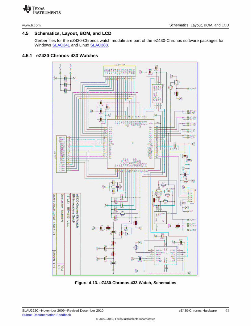
www.ti.com Schematics, Layout, BOM, and LCD
4.5 Schematics, Layout, BOM, and LCD
Gerber files for the eZ430-Chronos watch module are part of the eZ430-Chronos software packages forWindows SLAC341 and Linux SLAC388.
4.5.1 eZ430-Chronos-433 Watches
Figure 4-13. eZ430-Chronos-433 Watch, Schematics
61SLAU292C–November 2009–Revised December 2010 eZ430-Chronos HardwareSubmit Documentation Feedback
© 2009–2010, Texas Instruments Incorporated
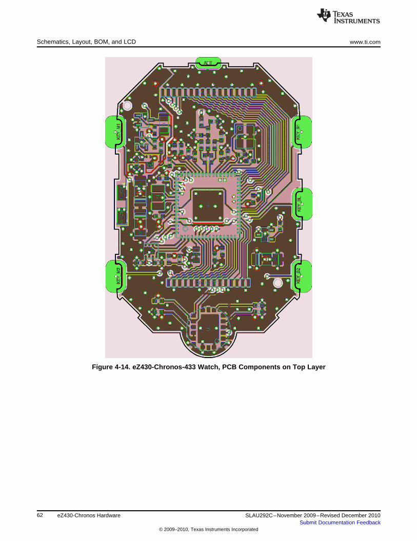
Schematics, Layout, BOM, and LCD www.ti.com
Figure 4-14. eZ430-Chronos-433 Watch, PCB Components on Top Layer
62 eZ430-Chronos Hardware SLAU292C–November 2009–Revised December 2010Submit Documentation Feedback
© 2009–2010, Texas Instruments Incorporated
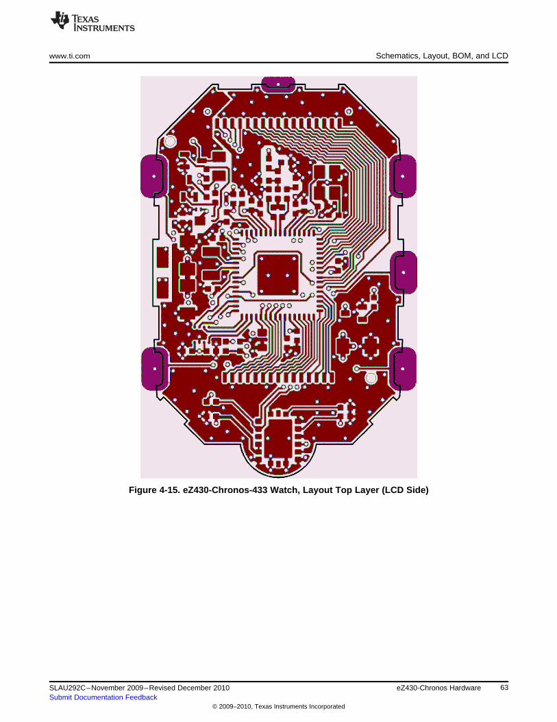
www.ti.com Schematics, Layout, BOM, and LCD
Figure 4-15. eZ430-Chronos-433 Watch, Layout Top Layer (LCD Side)
63SLAU292C–November 2009–Revised December 2010 eZ430-Chronos HardwareSubmit Documentation Feedback
© 2009–2010, Texas Instruments Incorporated
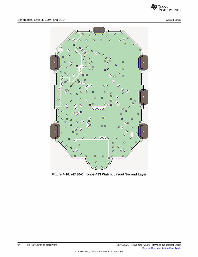
Schematics, Layout, BOM, and LCD www.ti.com
Figure 4-16. eZ430-Chronos-433 Watch, Layout Second Layer
64 eZ430-Chronos Hardware SLAU292C–November 2009–Revised December 2010Submit Documentation Feedback
© 2009–2010, Texas Instruments Incorporated
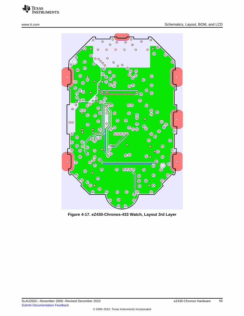
www.ti.com Schematics, Layout, BOM, and LCD
Figure 4-17. eZ430-Chronos-433 Watch, Layout 3rd Layer
65SLAU292C–November 2009–Revised December 2010 eZ430-Chronos HardwareSubmit Documentation Feedback
© 2009–2010, Texas Instruments Incorporated
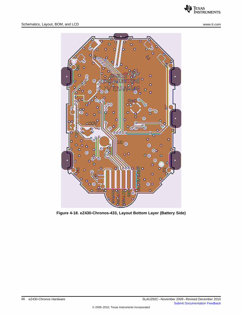
Schematics, Layout, BOM, and LCD www.ti.com
Figure 4-18. eZ430-Chronos-433, Layout Bottom Layer (Battery Side)
66 eZ430-Chronos Hardware SLAU292C–November 2009–Revised December 2010Submit Documentation Feedback
© 2009–2010, Texas Instruments Incorporated
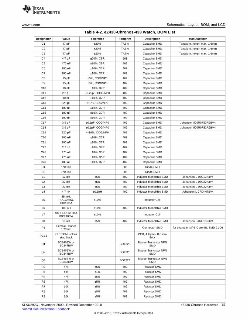
www.ti.com Schematics, Layout, BOM, and LCD
Table 4-2. eZ430-Chronos-433 Watch, BOM List
Designator Value Tolerance Footprint Description Manufacturer
C1 47 µF ±20% TAJ-A Capacitor SMD Tantalum, height max. 1.6mm
C2 47 µF ±20% TAJ-A Capacitor SMD Tantalum, height max. 1.6mm
C3 47 µF ±20% TAJ-A Capacitor SMD Tantalum, height max. 1.6mm
C4 4.7 µF ±20%, X5R 603 Capacitor SMD
C5 470 nF ±10%, X5R 402 Capacitor SMD
C6 100 nF ±10%, X7R 402 Capacitor SMD
C7 100 nF ±10%, X7R 402 Capacitor SMD
C8 15 pF ±5%, COG/NP0 402 Capacitor SMD
C9 15 pF ±5%, COG/NP0 402 Capacitor SMD
C10 10 nF ±10%, X7R 402 Capacitor SMD
C11 2.2 pF ±0.25pF, COG/NP0 402 Capacitor SMD
C12 10 nF ±10%, X7R 402 Capacitor SMD
C13 220 pF ±10%, COG/NP0 402 Capacitor SMD
C14 100 nF ±10%, X7R 402 Capacitor SMD
C15 100 nF ±10%, X7R 402 Capacitor SMD
C16 100 nF ±10%, X7R 402 Capacitor SMD
C17 3.9 pF ±0.1pF, COG/NP0 402 Capacitor SMD Johanson 500R07S3R9BV4
C18 3.9 pF ±0.1pF, COG/NP0 402 Capacitor SMD Johanson 500R07S3R9BV4
C19 220 pF +-10%, COG/NP0 402 Capacitor SMD
C20 100 nF ±10%, X7R 402 Capacitor SMD
C21 100 nF ±10%, X7R 402 Capacitor SMD
C22 2.2 nF ±10%, X7R 402 Capacitor SMD
C26 470 nF ±10%, X5R 402 Capacitor SMD
C27 470 nF ±10%, X5R 402 Capacitor SMD
C28 100 nF ±10%, X7R 402 Capacitor SMD
D1 1N4148 805 Diode SMD
D2 1N4148 805 Diode SMD
L1 12 nH ±5% 402 Inductor Monolithic SMD Johanson L-07C12NJV4
L2 27 nH ±5% 402 Inductor Monolithic SMD Johanson L-07C27NJV4
L3 27 nH ±5% 402 Inductor Monolithic SMD Johanson L-07C27NJV4
L4 4.7 nH ±0.3nH 402 Inductor Monolithic SMD Johanson L-07C4N7SV4
35 mH,L5 RDC≤250Ω, ±10% Inductor Coil
IDC≥1mA
L6 100 nH ±10% 402 Inductor Monolithic SMD
4mH, RDC≤100Ω,L7 ±10% Inductor CoilIDC≥10mA
L8 18 nH ±5% 402 Inductor Monolithic SMD Johanson L-07C18NJV4
Female HeaderP1 Connector SMD for example, MPE-Garry BL SMD 91-061.27mm
CUSTOM, solder PCB, 4 layers, 0.6 mmPCB1 stop black thick
BC846BW or Bipolar Transistor NPNQ1 SOT323BC847BW SMD
BC846BW or Bipolar Transistor NPNQ2 SOT323BC847BW SMD
BC846BW or Bipolar Transistor NPNQ3 SOT323BC847BW SMD
R2 47k ±5% 402 Resistor SMD
R3 56k ±1% 402 Resistor SMD
R4 47k ±5% 402 Resistor SMD
R5 47k ±5% 402 Resistor SMD
R7 10k ±5% 402 Resistor SMD
R8 10k ±5% 402 Resistor SMD
R9 10k ±5% 402 Resistor SMD
67SLAU292C–November 2009–Revised December 2010 eZ430-Chronos HardwareSubmit Documentation Feedback
© 2009–2010, Texas Instruments Incorporated
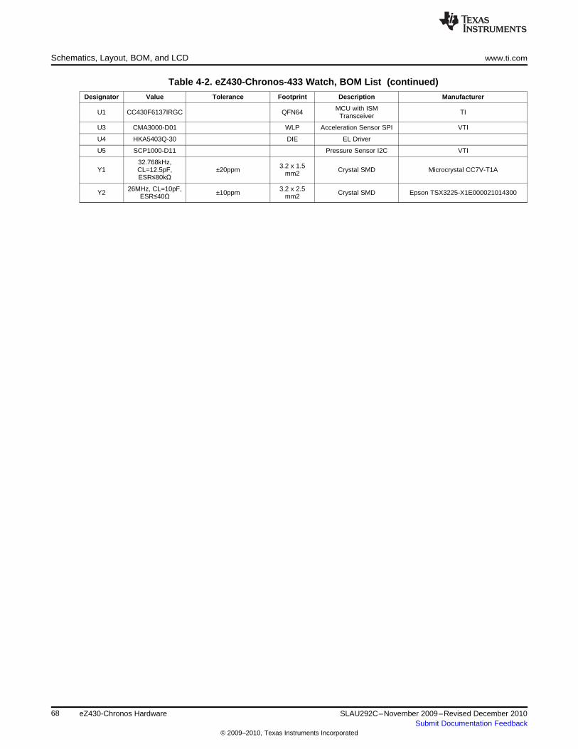
Schematics, Layout, BOM, and LCD www.ti.com
Table 4-2. eZ430-Chronos-433 Watch, BOM List (continued)
Designator Value Tolerance Footprint Description Manufacturer
MCU with ISMU1 CC430F6137IRGC QFN64 TITransceiver
U3 CMA3000-D01 WLP Acceleration Sensor SPI VTI
U4 HKA5403Q-30 DIE EL Driver
U5 SCP1000-D11 Pressure Sensor I2C VTI
32.768kHz, 3.2 x 1.5Y1 CL=12.5pF, ±20ppm Crystal SMD Microcrystal CC7V-T1Amm2ESR≤80kΩ
26MHz, CL=10pF, 3.2 x 2.5Y2 ±10ppm Crystal SMD Epson TSX3225-X1E000021014300ESR≤40Ω mm2
68 eZ430-Chronos Hardware SLAU292C–November 2009–Revised December 2010Submit Documentation Feedback
© 2009–2010, Texas Instruments Incorporated
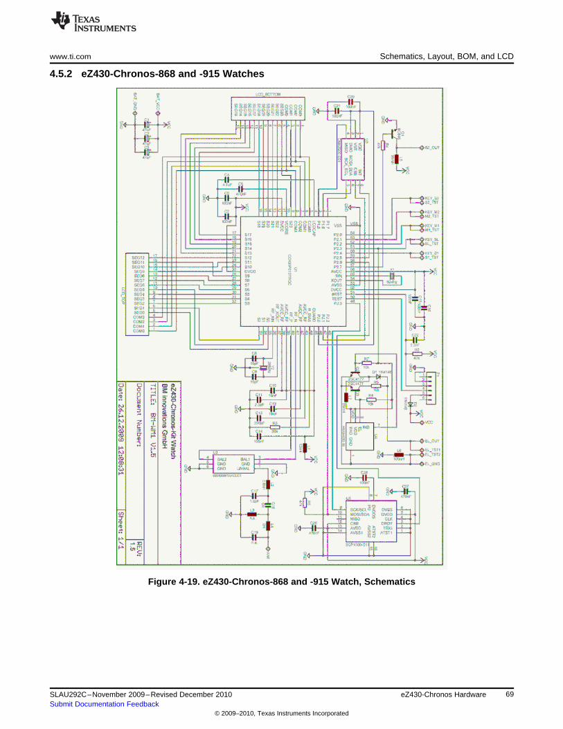
www.ti.com Schematics, Layout, BOM, and LCD
4.5.2 eZ430-Chronos-868 and -915 Watches
Figure 4-19. eZ430-Chronos-868 and -915 Watch, Schematics
69SLAU292C–November 2009–Revised December 2010 eZ430-Chronos HardwareSubmit Documentation Feedback
© 2009–2010, Texas Instruments Incorporated
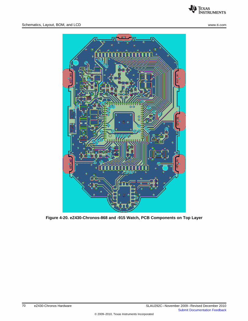
Schematics, Layout, BOM, and LCD www.ti.com
Figure 4-20. eZ430-Chronos-868 and -915 Watch, PCB Components on Top Layer
70 eZ430-Chronos Hardware SLAU292C–November 2009–Revised December 2010Submit Documentation Feedback
© 2009–2010, Texas Instruments Incorporated
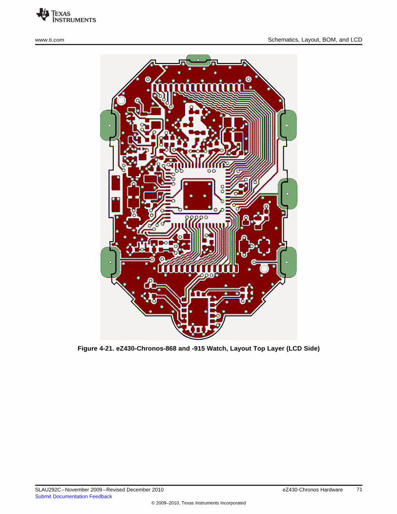
www.ti.com Schematics, Layout, BOM, and LCD
Figure 4-21. eZ430-Chronos-868 and -915 Watch, Layout Top Layer (LCD Side)
71SLAU292C–November 2009–Revised December 2010 eZ430-Chronos HardwareSubmit Documentation Feedback
© 2009–2010, Texas Instruments Incorporated
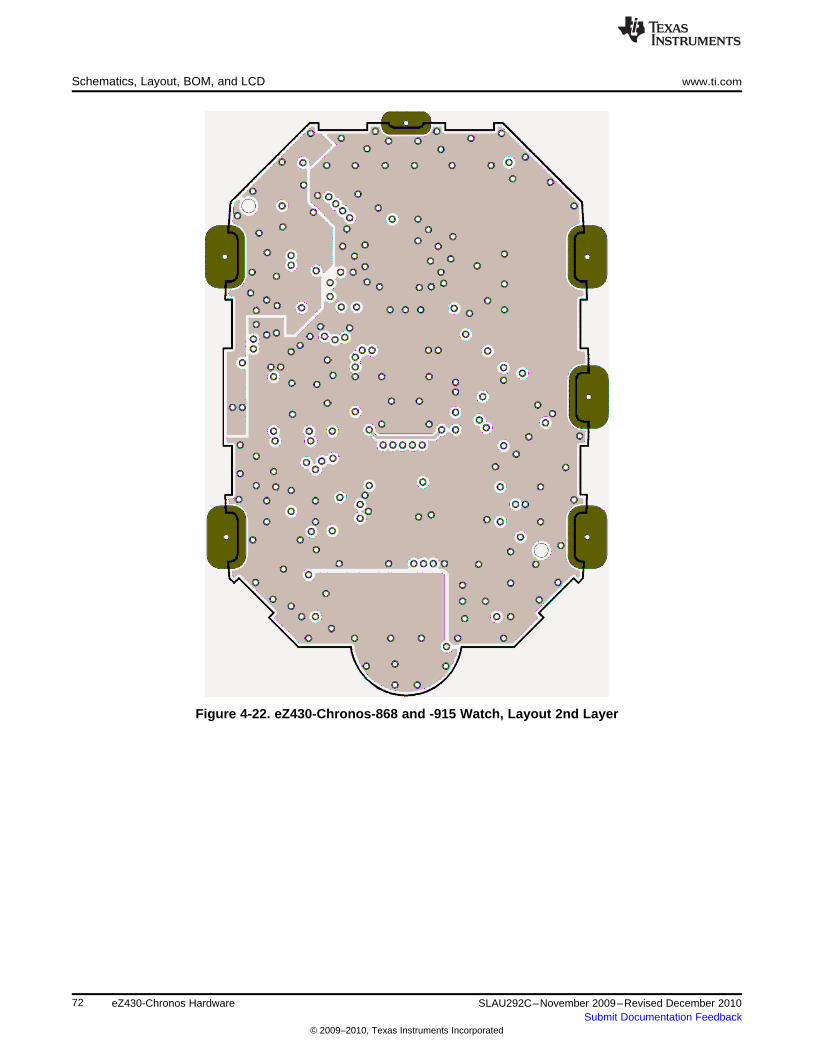
Schematics, Layout, BOM, and LCD www.ti.com
Figure 4-22. eZ430-Chronos-868 and -915 Watch, Layout 2nd Layer
72 eZ430-Chronos Hardware SLAU292C–November 2009–Revised December 2010Submit Documentation Feedback
© 2009–2010, Texas Instruments Incorporated
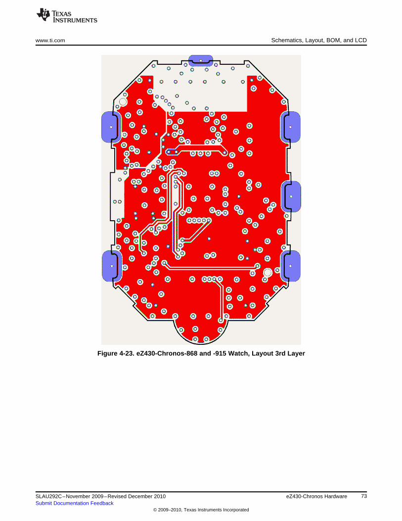
www.ti.com Schematics, Layout, BOM, and LCD
Figure 4-23. eZ430-Chronos-868 and -915 Watch, Layout 3rd Layer
73SLAU292C–November 2009–Revised December 2010 eZ430-Chronos HardwareSubmit Documentation Feedback
© 2009–2010, Texas Instruments Incorporated
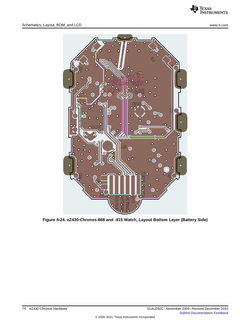
Schematics, Layout, BOM, and LCD www.ti.com
Figure 4-24. eZ430-Chronos-868 and -915 Watch, Layout Bottom Layer (Battery Side)
74 eZ430-Chronos Hardware SLAU292C–November 2009–Revised December 2010Submit Documentation Feedback
© 2009–2010, Texas Instruments Incorporated
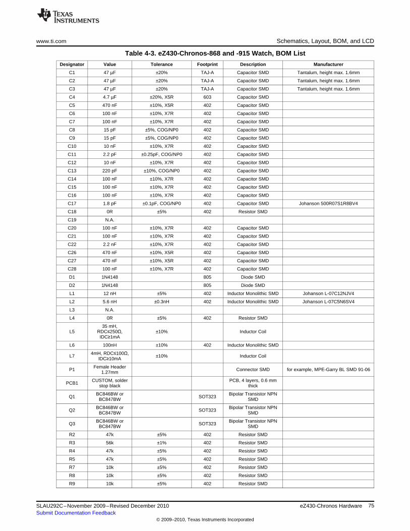
www.ti.com Schematics, Layout, BOM, and LCD
Table 4-3. eZ430-Chronos-868 and -915 Watch, BOM List
Designator Value Tolerance Footprint Description Manufacturer
C1 47 µF ±20% TAJ-A Capacitor SMD Tantalum, height max. 1.6mm
C2 47 µF ±20% TAJ-A Capacitor SMD Tantalum, height max. 1.6mm
C3 47 µF ±20% TAJ-A Capacitor SMD Tantalum, height max. 1.6mm
C4 4.7 µF ±20%, X5R 603 Capacitor SMD
C5 470 nF ±10%, X5R 402 Capacitor SMD
C6 100 nF ±10%, X7R 402 Capacitor SMD
C7 100 nF ±10%, X7R 402 Capacitor SMD
C8 15 pF ±5%, COG/NP0 402 Capacitor SMD
C9 15 pF ±5%, COG/NP0 402 Capacitor SMD
C10 10 nF ±10%, X7R 402 Capacitor SMD
C11 2.2 pF ±0.25pF, COG/NP0 402 Capacitor SMD
C12 10 nF ±10%, X7R 402 Capacitor SMD
C13 220 pF ±10%, COG/NP0 402 Capacitor SMD
C14 100 nF ±10%, X7R 402 Capacitor SMD
C15 100 nF ±10%, X7R 402 Capacitor SMD
C16 100 nF ±10%, X7R 402 Capacitor SMD
C17 1.8 pF ±0.1pF, COG/NP0 402 Capacitor SMD Johanson 500R07S1R8BV4
C18 0R ±5% 402 Resistor SMD
C19 N.A.
C20 100 nF ±10%, X7R 402 Capacitor SMD
C21 100 nF ±10%, X7R 402 Capacitor SMD
C22 2.2 nF ±10%, X7R 402 Capacitor SMD
C26 470 nF ±10%, X5R 402 Capacitor SMD
C27 470 nF ±10%, X5R 402 Capacitor SMD
C28 100 nF ±10%, X7R 402 Capacitor SMD
D1 1N4148 805 Diode SMD
D2 1N4148 805 Diode SMD
L1 12 nH ±5% 402 Inductor Monolithic SMD Johanson L-07C12NJV4
L2 5.6 nH ±0.3nH 402 Inductor Monolithic SMD Johanson L-07C5N6SV4
L3 N.A.
L4 0R ±5% 402 Resistor SMD
35 mH,L5 RDC≤250Ω, ±10% Inductor Coil
IDC≥1mA
L6 100nH ±10% 402 Inductor Monolithic SMD
4mH, RDC≤100Ω,L7 ±10% Inductor CoilIDC≥10mA
Female HeaderP1 Connector SMD for example, MPE-Garry BL SMD 91-061.27mm
CUSTOM, solder PCB, 4 layers, 0.6 mmPCB1 stop black thick
BC846BW or Bipolar Transistor NPNQ1 SOT323BC847BW SMD
BC846BW or Bipolar Transistor NPNQ2 SOT323BC847BW SMD
BC846BW or Bipolar Transistor NPNQ3 SOT323BC847BW SMD
R2 47k ±5% 402 Resistor SMD
R3 56k ±1% 402 Resistor SMD
R4 47k ±5% 402 Resistor SMD
R5 47k ±5% 402 Resistor SMD
R7 10k ±5% 402 Resistor SMD
R8 10k ±5% 402 Resistor SMD
R9 10k ±5% 402 Resistor SMD
75SLAU292C–November 2009–Revised December 2010 eZ430-Chronos HardwareSubmit Documentation Feedback
© 2009–2010, Texas Instruments Incorporated
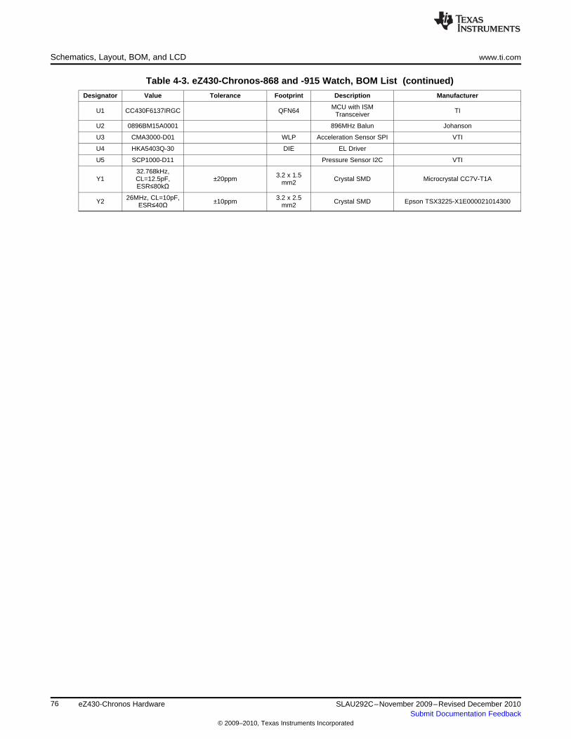
Schematics, Layout, BOM, and LCD www.ti.com
Table 4-3. eZ430-Chronos-868 and -915 Watch, BOM List (continued)
Designator Value Tolerance Footprint Description Manufacturer
MCU with ISMU1 CC430F6137IRGC QFN64 TITransceiver
U2 0896BM15A0001 896MHz Balun Johanson
U3 CMA3000-D01 WLP Acceleration Sensor SPI VTI
U4 HKA5403Q-30 DIE EL Driver
U5 SCP1000-D11 Pressure Sensor I2C VTI
32.768kHz, 3.2 x 1.5Y1 CL=12.5pF, ±20ppm Crystal SMD Microcrystal CC7V-T1Amm2ESR≤80kΩ
26MHz, CL=10pF, 3.2 x 2.5Y2 ±10ppm Crystal SMD Epson TSX3225-X1E000021014300ESR≤40Ω mm2
76 eZ430-Chronos Hardware SLAU292C–November 2009–Revised December 2010Submit Documentation Feedback
© 2009–2010, Texas Instruments Incorporated
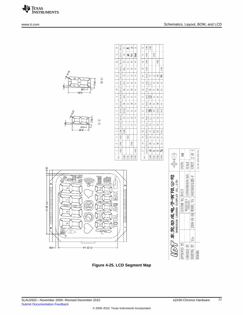
www.ti.com Schematics, Layout, BOM, and LCD
Figure 4-25. LCD Segment Map
77SLAU292C–November 2009–Revised December 2010 eZ430-Chronos HardwareSubmit Documentation Feedback
© 2009–2010, Texas Instruments Incorporated
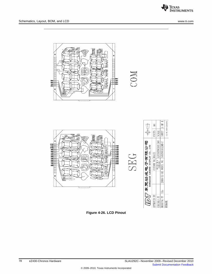
Schematics, Layout, BOM, and LCD www.ti.com
Figure 4-26. LCD Pinout
78 eZ430-Chronos Hardware SLAU292C–November 2009–Revised December 2010Submit Documentation Feedback
© 2009–2010, Texas Instruments Incorporated
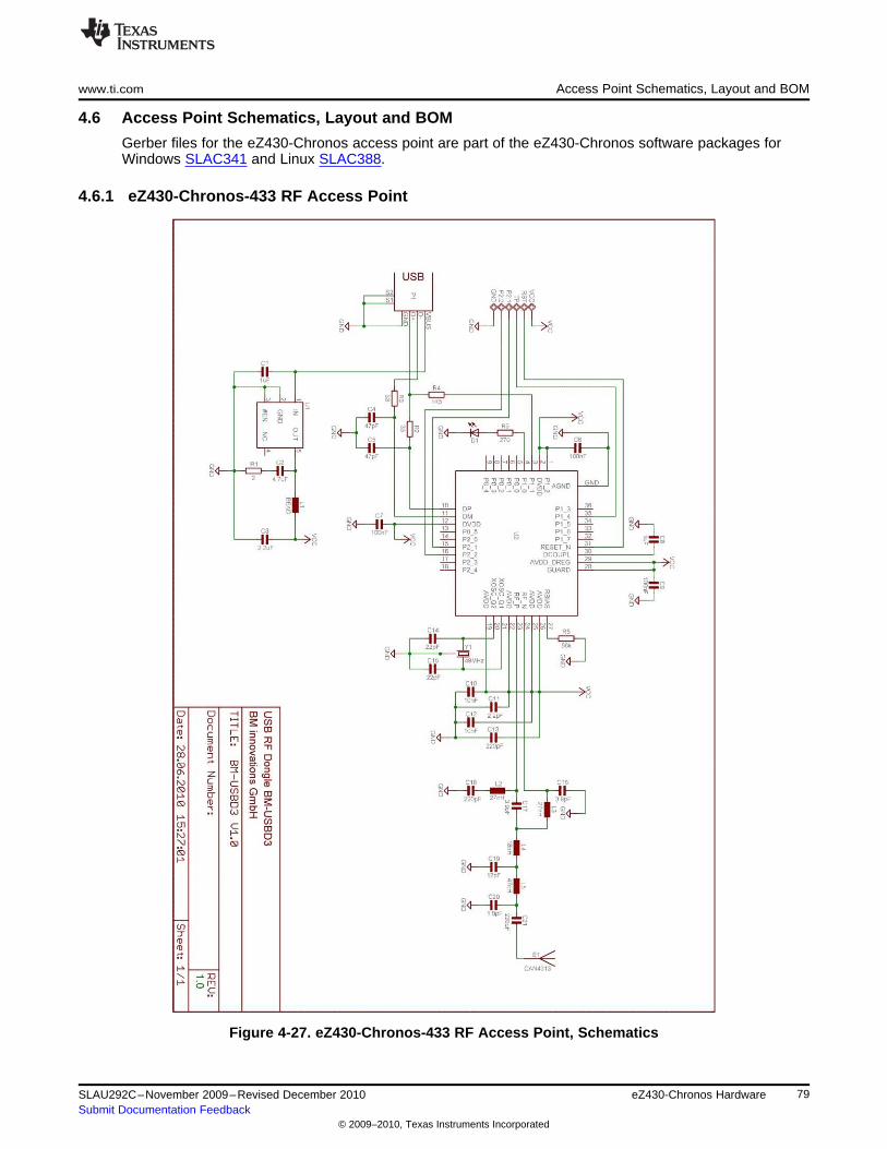
www.ti.com Access Point Schematics, Layout and BOM
4.6 Access Point Schematics, Layout and BOM
Gerber files for the eZ430-Chronos access point are part of the eZ430-Chronos software packages forWindows SLAC341 and Linux SLAC388.
4.6.1 eZ430-Chronos-433 RF Access Point
Figure 4-27. eZ430-Chronos-433 RF Access Point, Schematics
79SLAU292C–November 2009–Revised December 2010 eZ430-Chronos HardwareSubmit Documentation Feedback
© 2009–2010, Texas Instruments Incorporated
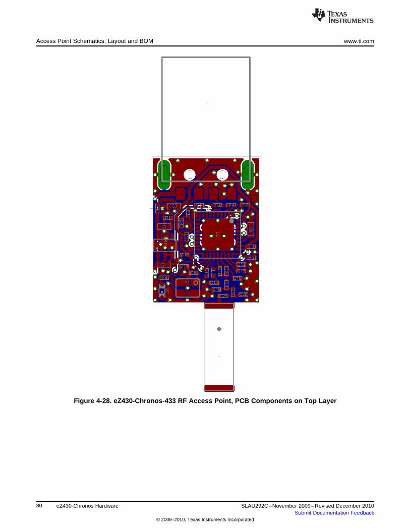
Access Point Schematics, Layout and BOM www.ti.com
Figure 4-28. eZ430-Chronos-433 RF Access Point, PCB Components on Top Layer
80 eZ430-Chronos Hardware SLAU292C–November 2009–Revised December 2010Submit Documentation Feedback
© 2009–2010, Texas Instruments Incorporated
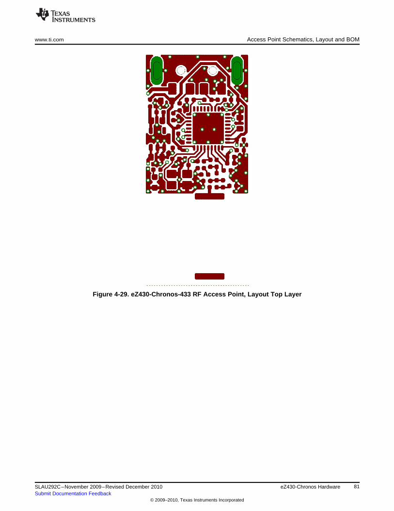
www.ti.com Access Point Schematics, Layout and BOM
Figure 4-29. eZ430-Chronos-433 RF Access Point, Layout Top Layer
81SLAU292C–November 2009–Revised December 2010 eZ430-Chronos HardwareSubmit Documentation Feedback
© 2009–2010, Texas Instruments Incorporated

Access Point Schematics, Layout and BOM www.ti.com
Figure 4-30. eZ430-Chronos-433 RF Access Point, Layout Bottom Layer
82 eZ430-Chronos Hardware SLAU292C–November 2009–Revised December 2010Submit Documentation Feedback
© 2009–2010, Texas Instruments Incorporated
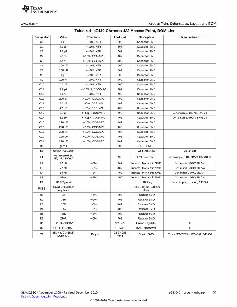
www.ti.com Access Point Schematics, Layout and BOM
Table 4-4. eZ430-Chronos-433 Access Point, BOM List
Designator Value Tolerance Footprint Description Manufacturer
C1 1 µF +-10%, X5R 603 Capacitor SMD
C2 4.7 µF +-10%, X5R 603 Capacitor SMD
C3 2.2 µF +-10%, X5R 603 Capacitor SMD
C4 47 pF +-10%, COG/NP0 402 Capacitor SMD
C5 47 pF +-10%, COG/NP0 402 Capacitor SMD
C6 100 nF +-10%, X7R 402 Capacitor SMD
C7 100 nF +-10%, X7R 402 Capacitor SMD
C8 1 µF +-10%, X5R 603 Capacitor SMD
C9 100 nF +-10%, X7R 402 Capacitor SMD
C10 10 nF +-10%, X7R 402 Capacitor SMD
C11 2.2 pF +-0.25pF, COG/NP0 402 Capacitor SMD
C12 10 nF +-10%, X7R 402 Capacitor SMD
C13 220 pF +-10%, COG/NP0 402 Capacitor SMD
C14 22 pF +-5%, COG/NP0 402 Capacitor SMD
C15 22 pF +-5%, COG/NP0 402 Capacitor SMD
C16 3.9 pF +-0.1pF, COG/NP0 402 Capacitor SMD Johanson 500R07S3R9BV4
C17 3.9 pF +-0.1pF, COG/NP0 402 Capacitor SMD Johanson 500R07S3R9BV4
C18 220 pF +-10%, COG/NP0 402 Capacitor SMD
C18 220 pF +-10%, COG/NP0 402 Capacitor SMD
C19 220 pF +-10%, COG/NP0 402 Capacitor SMD
C20 220 pF +-10%, COG/NP0 402 Capacitor SMD
C21 220 pF +-10%, COG/NP0 402 Capacitor SMD
D1 green 603 LED SMD
E1 0868AT43A0020 Chip Antenna Johanson
Ferrite Bead 1k,L1 402 EMI Filter SMD for example, TDK MMZ1005S102C1R, min. 100mA
L2 27 nH +-5% 402 Inductor Monolithic SMD Johanson L-07C27NJV4
L3 27 nH +-5% 402 Inductor Monolithic SMD Johanson L-07C27NJV4
L4 18 nH +-5% 402 Inductor Monolithic SMD Johanson L-07C18NJV4
L5 47nH +-5% 402 Inductor Monolithic SMD Johanson L-07C47NJV4
P1 USB Type A USB Plug for example, Lumberg 241007
CUSTOM, solder PCB, 2 layers, 0.8 mmPCB1 stop black thick
R1 2R +-5% 402 Resistor SMD
R2 33R +-5% 402 Resistor SMD
R3 33R +-5% 402 Resistor SMD
R4 1.5k +-5% 402 Resistor SMD
R5 56k +-1% 402 Resistor SMD
R6 270R +-5% 402 Resistor SMD
U1 TPS76933DBV SOT-23 Linear Regulator TI
U2 CC1111F32RSP QFN36 ISM Transceiver TI
48MHz, CL=16pF, 23.2 x 2.5Y1 +-10ppm Crystal SMD Epson TSX3225-X1E000021040300ESR≤40Ω mm2
83SLAU292C–November 2009–Revised December 2010 eZ430-Chronos HardwareSubmit Documentation Feedback
© 2009–2010, Texas Instruments Incorporated
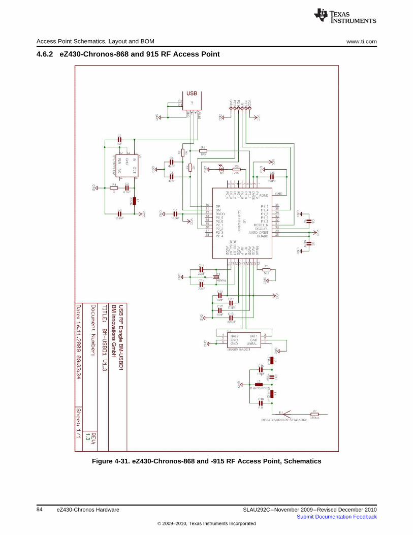
Access Point Schematics, Layout and BOM www.ti.com
4.6.2 eZ430-Chronos-868 and 915 RF Access Point
Figure 4-31. eZ430-Chronos-868 and -915 RF Access Point, Schematics
84 eZ430-Chronos Hardware SLAU292C–November 2009–Revised December 2010Submit Documentation Feedback
© 2009–2010, Texas Instruments Incorporated
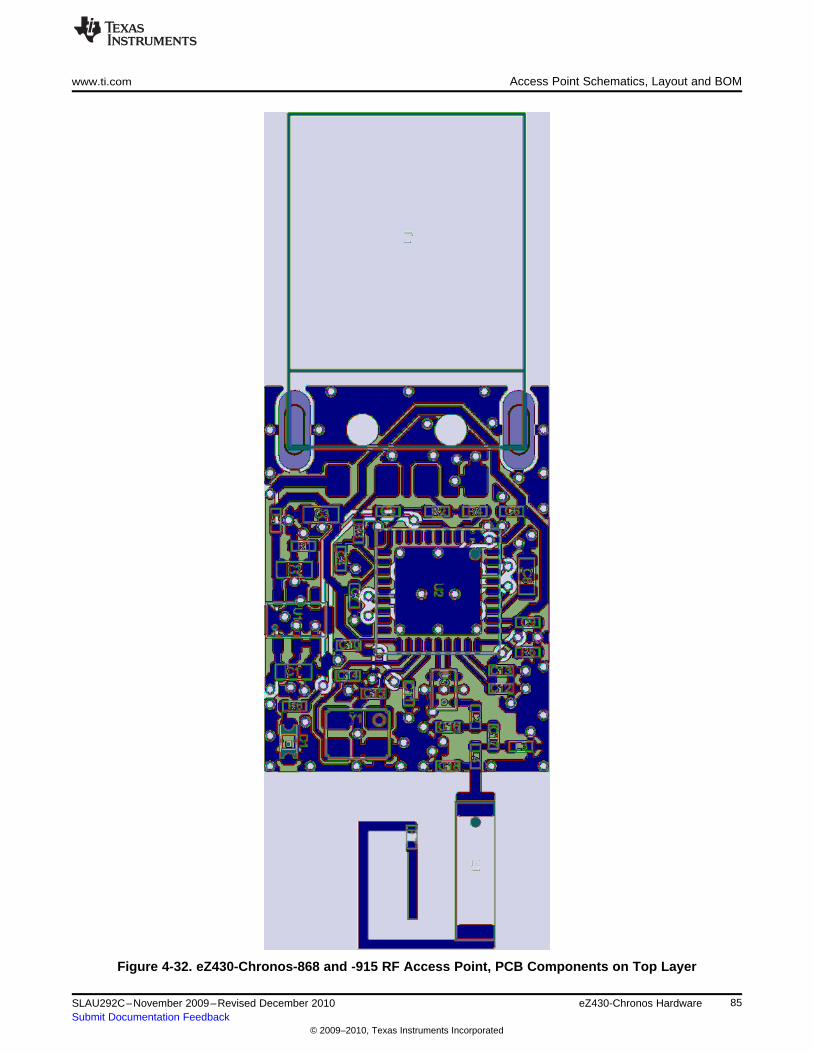
www.ti.com Access Point Schematics, Layout and BOM
Figure 4-32. eZ430-Chronos-868 and -915 RF Access Point, PCB Components on Top Layer
85SLAU292C–November 2009–Revised December 2010 eZ430-Chronos HardwareSubmit Documentation Feedback
© 2009–2010, Texas Instruments Incorporated
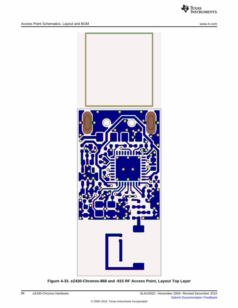
Access Point Schematics, Layout and BOM www.ti.com
Figure 4-33. eZ430-Chronos-868 and -915 RF Access Point, Layout Top Layer
86 eZ430-Chronos Hardware SLAU292C–November 2009–Revised December 2010Submit Documentation Feedback
© 2009–2010, Texas Instruments Incorporated

www.ti.com Access Point Schematics, Layout and BOM
Figure 4-34. eZ430-Chronos-868 and -915 RF Access Point, Layout Bottom Layer
87SLAU292C–November 2009–Revised December 2010 eZ430-Chronos HardwareSubmit Documentation Feedback
© 2009–2010, Texas Instruments Incorporated
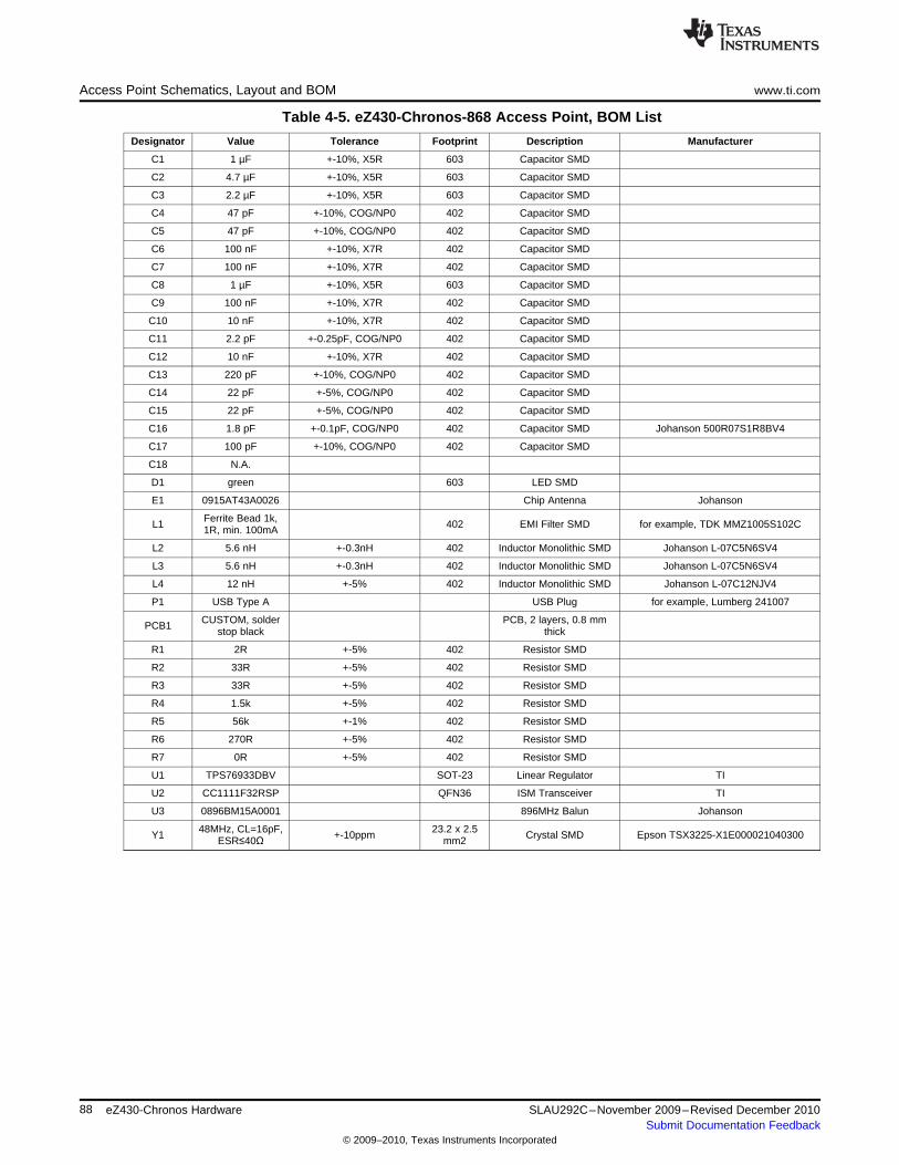
Access Point Schematics, Layout and BOM www.ti.com
Table 4-5. eZ430-Chronos-868 Access Point, BOM List
Designator Value Tolerance Footprint Description Manufacturer
C1 1 µF +-10%, X5R 603 Capacitor SMD
C2 4.7 µF +-10%, X5R 603 Capacitor SMD
C3 2.2 µF +-10%, X5R 603 Capacitor SMD
C4 47 pF +-10%, COG/NP0 402 Capacitor SMD
C5 47 pF +-10%, COG/NP0 402 Capacitor SMD
C6 100 nF +-10%, X7R 402 Capacitor SMD
C7 100 nF +-10%, X7R 402 Capacitor SMD
C8 1 µF +-10%, X5R 603 Capacitor SMD
C9 100 nF +-10%, X7R 402 Capacitor SMD
C10 10 nF +-10%, X7R 402 Capacitor SMD
C11 2.2 pF +-0.25pF, COG/NP0 402 Capacitor SMD
C12 10 nF +-10%, X7R 402 Capacitor SMD
C13 220 pF +-10%, COG/NP0 402 Capacitor SMD
C14 22 pF +-5%, COG/NP0 402 Capacitor SMD
C15 22 pF +-5%, COG/NP0 402 Capacitor SMD
C16 1.8 pF +-0.1pF, COG/NP0 402 Capacitor SMD Johanson 500R07S1R8BV4
C17 100 pF +-10%, COG/NP0 402 Capacitor SMD
C18 N.A.
D1 green 603 LED SMD
E1 0915AT43A0026 Chip Antenna Johanson
Ferrite Bead 1k,L1 402 EMI Filter SMD for example, TDK MMZ1005S102C1R, min. 100mA
L2 5.6 nH +-0.3nH 402 Inductor Monolithic SMD Johanson L-07C5N6SV4
L3 5.6 nH +-0.3nH 402 Inductor Monolithic SMD Johanson L-07C5N6SV4
L4 12 nH +-5% 402 Inductor Monolithic SMD Johanson L-07C12NJV4
P1 USB Type A USB Plug for example, Lumberg 241007
CUSTOM, solder PCB, 2 layers, 0.8 mmPCB1 stop black thick
R1 2R +-5% 402 Resistor SMD
R2 33R +-5% 402 Resistor SMD
R3 33R +-5% 402 Resistor SMD
R4 1.5k +-5% 402 Resistor SMD
R5 56k +-1% 402 Resistor SMD
R6 270R +-5% 402 Resistor SMD
R7 0R +-5% 402 Resistor SMD
U1 TPS76933DBV SOT-23 Linear Regulator TI
U2 CC1111F32RSP QFN36 ISM Transceiver TI
U3 0896BM15A0001 896MHz Balun Johanson
48MHz, CL=16pF, 23.2 x 2.5Y1 +-10ppm Crystal SMD Epson TSX3225-X1E000021040300ESR≤40Ω mm2
88 eZ430-Chronos Hardware SLAU292C–November 2009–Revised December 2010Submit Documentation Feedback
© 2009–2010, Texas Instruments Incorporated
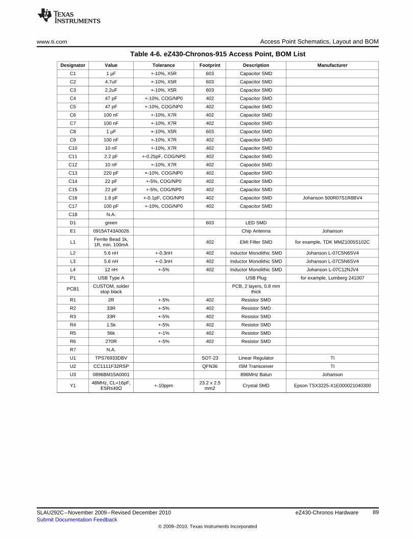
www.ti.com Access Point Schematics, Layout and BOM
Table 4-6. eZ430-Chronos-915 Access Point, BOM List
Designator Value Tolerance Footprint Description Manufacturer
C1 1 µF +-10%, X5R 603 Capacitor SMD
C2 4.7uF +-10%, X5R 603 Capacitor SMD
C3 2.2uF +-10%, X5R 603 Capacitor SMD
C4 47 pF +-10%, COG/NP0 402 Capacitor SMD
C5 47 pF +-10%, COG/NP0 402 Capacitor SMD
C6 100 nF +-10%, X7R 402 Capacitor SMD
C7 100 nF +-10%, X7R 402 Capacitor SMD
C8 1 µF +-10%, X5R 603 Capacitor SMD
C9 100 nF +-10%, X7R 402 Capacitor SMD
C10 10 nF +-10%, X7R 402 Capacitor SMD
C11 2.2 pF +-0.25pF, COG/NP0 402 Capacitor SMD
C12 10 nF +-10%, X7R 402 Capacitor SMD
C13 220 pF +-10%, COG/NP0 402 Capacitor SMD
C14 22 pF +-5%, COG/NP0 402 Capacitor SMD
C15 22 pF +-5%, COG/NP0 402 Capacitor SMD
C16 1.8 pF +-0.1pF, COG/NP0 402 Capacitor SMD Johanson 500R07S1R8BV4
C17 100 pF +-10%, COG/NP0 402 Capacitor SMD
C18 N.A.
D1 green 603 LED SMD
E1 0915AT43A0026 Chip Antenna Johanson
Ferrite Bead 1k,L1 402 EMI Filter SMD for example, TDK MMZ1005S102C1R, min. 100mA
L2 5.6 nH +-0.3nH 402 Inductor Monolithic SMD Johanson L-07C5N6SV4
L3 5.6 nH +-0.3nH 402 Inductor Monolithic SMD Johanson L-07C5N6SV4
L4 12 nH +-5% 402 Inductor Monolithic SMD Johanson L-07C12NJV4
P1 USB Type A USB Plug for example, Lumberg 241007
CUSTOM, solder PCB, 2 layers, 0.8 mmPCB1 stop black thick
R1 2R +-5% 402 Resistor SMD
R2 33R +-5% 402 Resistor SMD
R3 33R +-5% 402 Resistor SMD
R4 1.5k +-5% 402 Resistor SMD
R5 56k +-1% 402 Resistor SMD
R6 270R +-5% 402 Resistor SMD
R7 N.A.
U1 TPS76933DBV SOT-23 Linear Regulator TI
U2 CC1111F32RSP QFN36 ISM Transceiver TI
U3 0896BM15A0001 896MHz Balun Johanson
48MHz, CL=16pF, 23.2 x 2.5Y1 +-10ppm Crystal SMD Epson TSX3225-X1E000021040300ESR≤40Ω mm2
89SLAU292C–November 2009–Revised December 2010 eZ430-Chronos HardwareSubmit Documentation Feedback
© 2009–2010, Texas Instruments Incorporated
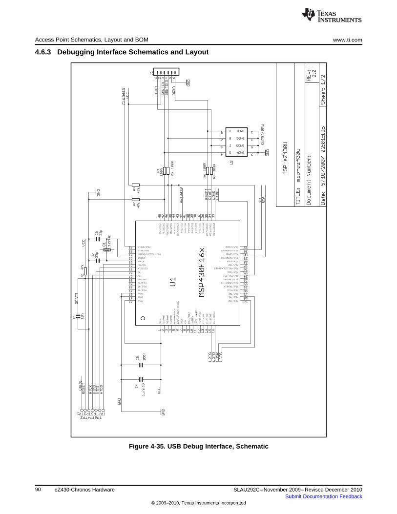
Access Point Schematics, Layout and BOM www.ti.com
4.6.3 Debugging Interface Schematics and Layout
Figure 4-35. USB Debug Interface, Schematic
90 eZ430-Chronos Hardware SLAU292C–November 2009–Revised December 2010Submit Documentation Feedback
© 2009–2010, Texas Instruments Incorporated
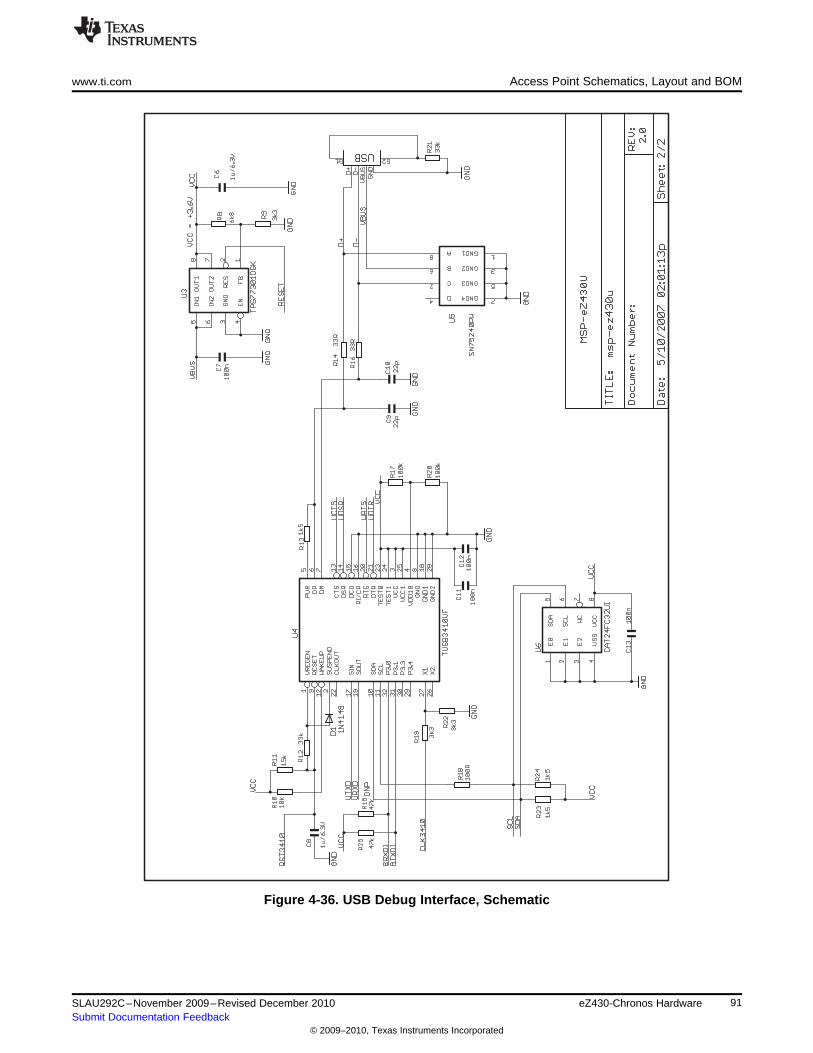
www.ti.com Access Point Schematics, Layout and BOM
Figure 4-36. USB Debug Interface, Schematic
91SLAU292C–November 2009–Revised December 2010 eZ430-Chronos HardwareSubmit Documentation Feedback
© 2009–2010, Texas Instruments Incorporated
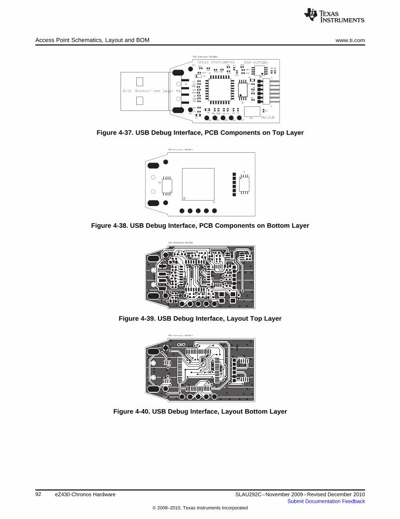
Access Point Schematics, Layout and BOM www.ti.com
Figure 4-37. USB Debug Interface, PCB Components on Top Layer
Figure 4-38. USB Debug Interface, PCB Components on Bottom Layer
Figure 4-39. USB Debug Interface, Layout Top Layer
Figure 4-40. USB Debug Interface, Layout Bottom Layer
92 eZ430-Chronos Hardware SLAU292C–November 2009–Revised December 2010Submit Documentation Feedback
© 2009–2010, Texas Instruments Incorporated
Appendix ASLAU292C–November 2009–Revised December 2010
Frequently Asked Questions
A.1 FAQs1. My eZ430-Chronos watch doesn't respond when I push buttons, instead it shows "Loct" in the
LCD?"Loct" on the 7-segment LCD stands for "Lock" and indicates that the keylock is active. By holding "#"and "DOWN" for 3 seconds simultaneously unlocks or locks the buttons. The LCDs shows "oPEn"when the keylock is disabled.
2. Why doesn't my eZ430-Chronos watch always respond when buttons are pushed?If buttons are pushed slowly (i.e., held down too long), button pushes are ignored.
3. Why doesn't my eZ430-Chronos respond when I try to push buttons in short intervals in PPT orACC mode?Especially in PPT mode it is important to avoid bouncing of the buttons. Therefore, an artificial delay onthe receiver side is implemented. Button pushes are translated into keystrokes or mouse clicks only ifthere is at least 0.5 seconds between two of them.
4. Is my eZ430-Chronos waterproof?Yes, it is 30-m waterproof. This indicates that it resists splashes and rain. However, it cannot be usedwhile taking a shower, swimming, diving, surfing, snorkeling or any other water sports. Set the watchbefore exposing it to excessive water. Pressing the buttons in water or heavy rainstorms may causewater to enter the watch.
5. The reported temperature is incorrect, how can I calibrate the sensor?A temperature offset is stored in Flash, which is calibrated at production. If the offset is erased or isincorrect, it can be changed to an appropriate level; see Section 3.2.1.3 for details.
6. The reported altitude is incorrect, why is that and how can I calibrate the sensor?The altitude is determined from barometric pressure. Therefore, the altimeter needs to be re-calibratedas the pressure changes with the weather. See Section 3.2.1.4 for details on how to calibrate thealtimeter. In addition, the altitude is a function of the temperature in addition to the barometricpressure. Therefore, the watch needs to have ambient temperature, wearing it on the arm or close tothe body may cause inaccurate measurements.
7. Why is there a timeout for the altimeter?The altimeter algorithm is implemented according to an application report from VTI. It is not optimizedfor ultra-low current consumption. For enhanced battery life, the altimeter stops operation after onehour. It can be re-activated by pushing the "UP" button.
8. How can TI sell the eZ430-Chronos for only US$49?The eZ430-Chronos kit is intended to be an attractive development kit and is not intended to be aconsumer product. Texas Instruments and the partner companies are sponsoring components orservices to increase the accessibility of flexible and innovative development systems to a broaderaudience. Consumer products usually retail for higher prices.
9. Why are the backchannel pins not connected on the eZ430-Chronos PCB despite the fact thatthe eZ430-Chronos debug interface supports the backchannel?All pins of the CC430 were used for the LCD, buttons, or sensors.
10. Why is there no JTAG connector on the RF access point?The access point is designed to be production ready and as small as possible. Therefore, no debugconnector is added. However, it may be reprogrammed by attaching a TI low power wireless debuginterface to the corresponding pads on the bottom side of the PCB, or using TI's CC1111EMK868-915.
93SLAU292C–November 2009–Revised December 2010 Frequently Asked QuestionsSubmit Documentation Feedback
© 2009–2010, Texas Instruments Incorporated
FAQs www.ti.com
11. When I try to compile the source code with IAR KickStart, I get the following error:Fatal Error[e89]: Too much object code produced (more than 0x4000 bytes) for this packageIAR KickStart currently has a 16KB code size limitation, and the project being compiled is larger than16KB (0x4000 = 16384). Select the limited project version in the Workspace pull-down menu of theIDE or use a full license of IAR. A 30-day evaluation version of IAR is available fromhttp://supp.iar.com/Download/SW/?item=EW430-EVAL.
12. When I try to compile the source code with Code Composer Studio v4.2, I get the followingerror:error: output file "eZ430_chronos_ISM_xxx.out exceeds code size limitCode Composer Studio v4.2 Core Edition is limited to 16kB of code size and the project beingcompiles is larger than 16KB. Select the limited project version in the Build Property Configuration pull-down menu of the IDE or use the Platinum Edition of CCS. A 30-day evaluation version is availablefrom http://tiexpressdsp.com/index.php/Category:Code_Composer_Studio_v4
13. What is the range of the eZ430-Chronos kit?In free field distances of up to 100 m (328 ft) have been measured. The range in other conditions,especially within buildings, is hard to predict. It also depends on the protocol stack that is used.
14. A button fell of the eZ430-Chronos housing after I re-assembled it.The buttons of the eZ430-Chronos watch housing are held by small C-clips. If the metal strips for thebuttons of the watch module bent and stuck at the watch housing buttons, they could have removedthe C-clip. Open the watch, locate the C-clip, and re-assemble the button.
15. How do I know whether I have a 915-MHz, 868-MHz, or 433-MHz kit?Each eZ430-Chronos kit has a sticker on the box that includes the part number/frequency. The 915-MHz/868-MHz watches are the same for both frequencies from a hardware perspective. The USBaccess points are slightly different. The 868-MHz version has a 0-Ω resistor next to the antenna, andthe 915-MHz version does not. The 433-MHz watches and access points (with blue antenna, largerthan 915-MHz/868-MHz versions) are different from a hardware and software perspective and cannotbe used for other frequencies.
16. How do I restore the original software on my eZ430-Chronos watch?The eZ430-Chronos software on the PC contains source code projects as well as Flash images, whichmay be used to restore the original software state of the watch module. The .txt files are located inC:\Program Files\Texas Instruments\eZ430-Chronos\Software Projects\Recovery. To program the .txtflash images tool such as the Flash Pro Lite software from Elprotronic (www.elprotronic.com) can beused. Ensure that the information memory block D is not erased, as it contains calibration data and theID of the watch module.
17. I have erased the watch module ID and calibration data. What happens now?If information memory block D was erased, default values for the calibration data and ID are used. Seefunction read_calibration_values() in main.c for details.
18. I have more than one eZ430-Chronos watch connecting to one access point at the same time.How can I prevent this?Each eZ430-Chronos kit has a unique ID stored in information memory block D. If this block waserased, the ID is equal on all watches. See FAQ item 17 about restoring the ID value.
19. Can I purchase the eZ430-Chronos kit or components of it in quantities? Can I get acustomized version?Yes, our partner BM innovations (http://www.bm-innovations.com) provides all components of theeZ430-Chronos kit in volume as well as a range of other products.
20. Which version of SimpliciTI is used with eZ430-Chronos?The current software release used SimpliciTI 1.1.1.
21. The LCD of my eZ430-Chronos remains blank after a wireless update. What can I do?In case of an error during the wireless update, the watch does not go back to the previous softwareversion as its Flash memory was deleted. To reduce current consumption, the watch is put in low-power mode (LPM4) and the LCD is turned off. As the wireless update software is still active, theupdate procedure can be started again despite the fact that the LCD remains blank. This can be done,by selecting a flash image (.txt file) on the wireless update tabs of the eZ430-Chronos Control CenterPC software and clicking on "Update eZ430-Chronos Watch". To start the update on the watch, pressthe "DOWN" button. The update is started. For details, see Section 3.6.3.
94 Frequently Asked Questions SLAU292C–November 2009–Revised December 2010Submit Documentation Feedback
© 2009–2010, Texas Instruments Incorporated
www.ti.com FAQs
22. The wireless update procedure always returns an error while downloading to flash.Please make sure that the file you are trying to download does not include data outside the main flashboundaries, which are 0x8000 – 0xFFFF. This protection mechanism avoids writing of data to non-existent or restricted addresses. Please try to download one of the original example project’s .txt,which are available for Windows in C:\Program Files\Texas Instruments\eZ430-Chronos\Recovery\eZ430-Chronos Watch\Applications and for Linux in /home/<user name>/TexasInstruments/eZ430-Chronos/Recovery/eZ430-Chronos Watch/Applications. If the update still doesn'twork, the RAM based updater may be corrupted. Please see next FAQ item.
23. The wireless update always returns an error while downloading to RAM.Please make sure that the file named "ram_based_updater.txt", which is located on the workingdirectory of your Control Center or Data Logger GUI has not been changed. If so, please re-install theeZ430-Chronos Software to restore the original file.
24. I get an error message right after I start the wireless update on the PC.Failed to start Wireless Update.Check if the RF access point contains right software version. Kits older than 04/2010 (date code canbe found on bottom of the eZ430-Chronos box) require a manual update as described in Section 3.6.3.
25. Activating the rFbSL mode on the watch always results in a rest.This is normal. Whenever the wireless update was activated on the watch, it returns to the mainapplication with a reset, regardless if an update was performed or not. Time, data, alarm, and otherRAM-based data is lost. For details, see Section 3.6.3.
26. The buzzer doesn't work when the watch is not inside the housing. What's wrong?This is normal as the buzzer is located on the metal back of the watch. It is only connected to thewatch module when the back is mounted on the watch.
95SLAU292C–November 2009–Revised December 2010 Frequently Asked QuestionsSubmit Documentation Feedback
© 2009–2010, Texas Instruments Incorporated
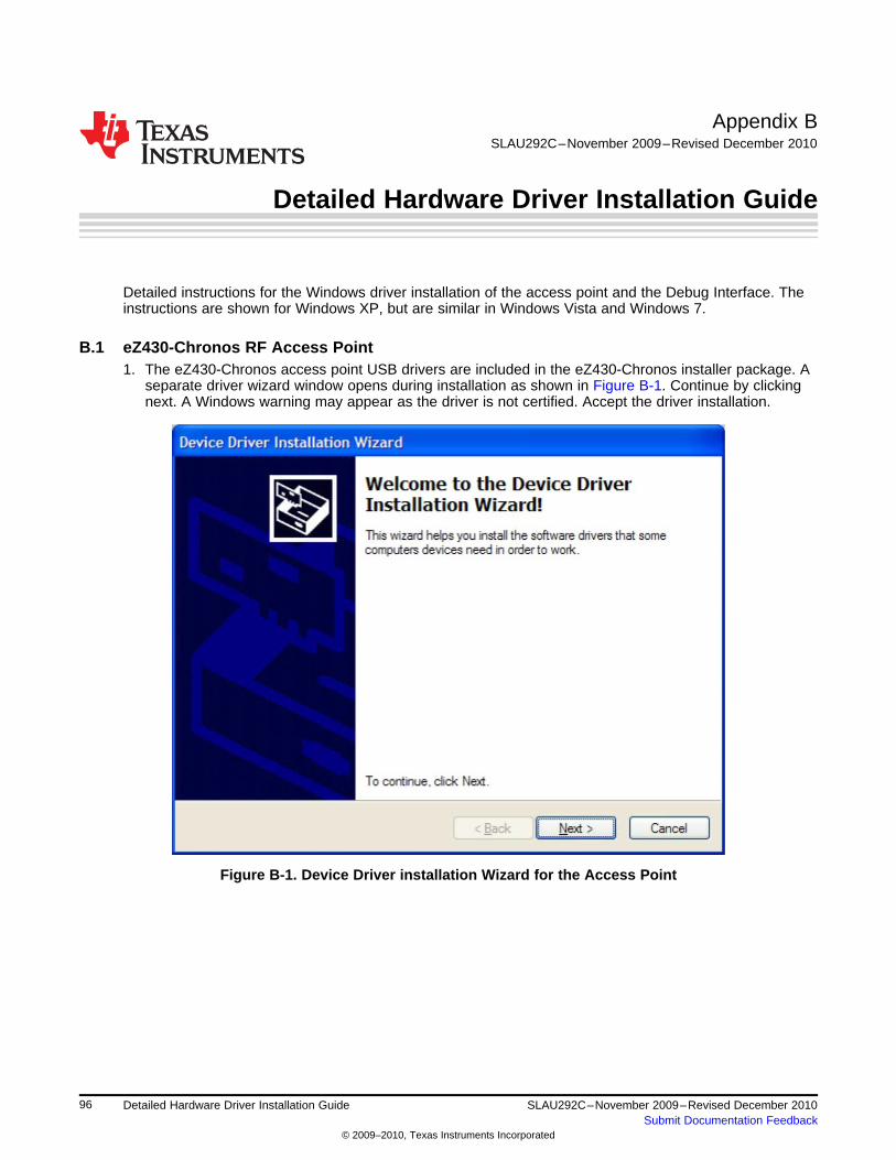
Appendix BSLAU292C–November 2009–Revised December 2010
Detailed Hardware Driver Installation Guide
Detailed instructions for the Windows driver installation of the access point and the Debug Interface. Theinstructions are shown for Windows XP, but are similar in Windows Vista and Windows 7.
B.1 eZ430-Chronos RF Access Point1. The eZ430-Chronos access point USB drivers are included in the eZ430-Chronos installer package. A
separate driver wizard window opens during installation as shown in Figure B-1. Continue by clickingnext. A Windows warning may appear as the driver is not certified. Accept the driver installation.
Figure B-1. Device Driver installation Wizard for the Access Point
96 Detailed Hardware Driver Installation Guide SLAU292C–November 2009–Revised December 2010Submit Documentation Feedback
© 2009–2010, Texas Instruments Incorporated
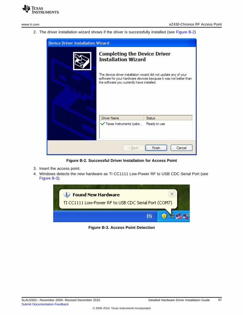
www.ti.com eZ430-Chronos RF Access Point
2. The driver installation wizard shows if the driver is successfully installed (see Figure B-2)
Figure B-2. Successful Driver Installation for Access Point
3. Insert the access point.4. Windows detects the new hardware as TI CC1111 Low-Power RF to USB CDC Serial Port (see
Figure B-3).
Figure B-3. Access Point Detection
97SLAU292C–November 2009–Revised December 2010 Detailed Hardware Driver Installation GuideSubmit Documentation Feedback
© 2009–2010, Texas Instruments Incorporated
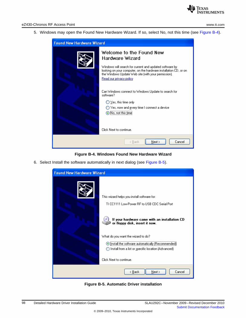
eZ430-Chronos RF Access Point www.ti.com
5. Windows may open the Found New Hardware Wizard. If so, select No, not this time (see Figure B-4).
Figure B-4. Windows Found New Hardware Wizard
6. Select Install the software automatically in next dialog (see Figure B-5).
Figure B-5. Automatic Driver installation
98 Detailed Hardware Driver Installation Guide SLAU292C–November 2009–Revised December 2010Submit Documentation Feedback
© 2009–2010, Texas Instruments Incorporated
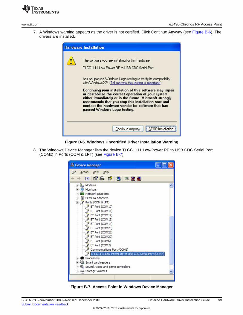
www.ti.com eZ430-Chronos RF Access Point
7. A Windows warning appears as the driver is not certified. Click Continue Anyway (see Figure B-6). Thedrivers are installed.
Figure B-6. Windows Uncertified Driver Installation Warning
8. The Windows Device Manager lists the device TI CC1111 Low-Power RF to USB CDC Serial Port(COMx) in Ports (COM & LPT) (see Figure B-7).
Figure B-7. Access Point in Windows Device Manager
99SLAU292C–November 2009–Revised December 2010 Detailed Hardware Driver Installation GuideSubmit Documentation Feedback
© 2009–2010, Texas Instruments Incorporated
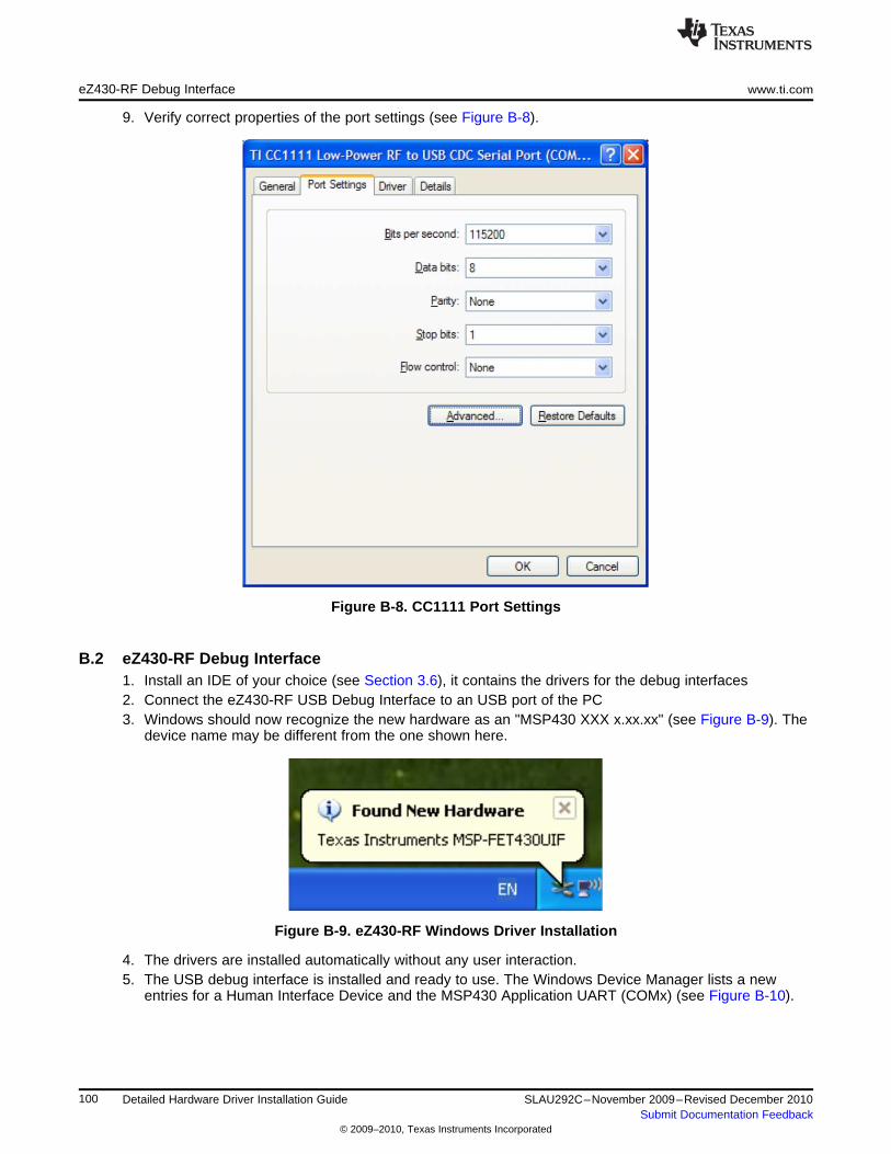
eZ430-RF Debug Interface www.ti.com
9. Verify correct properties of the port settings (see Figure B-8).
Figure B-8. CC1111 Port Settings
B.2 eZ430-RF Debug Interface1. Install an IDE of your choice (see Section 3.6), it contains the drivers for the debug interfaces2. Connect the eZ430-RF USB Debug Interface to an USB port of the PC3. Windows should now recognize the new hardware as an "MSP430 XXX x.xx.xx" (see Figure B-9). The
device name may be different from the one shown here.
Figure B-9. eZ430-RF Windows Driver Installation
4. The drivers are installed automatically without any user interaction.5. The USB debug interface is installed and ready to use. The Windows Device Manager lists a new
entries for a Human Interface Device and the MSP430 Application UART (COMx) (see Figure B-10).
100 Detailed Hardware Driver Installation Guide SLAU292C–November 2009–Revised December 2010Submit Documentation Feedback
© 2009–2010, Texas Instruments Incorporated
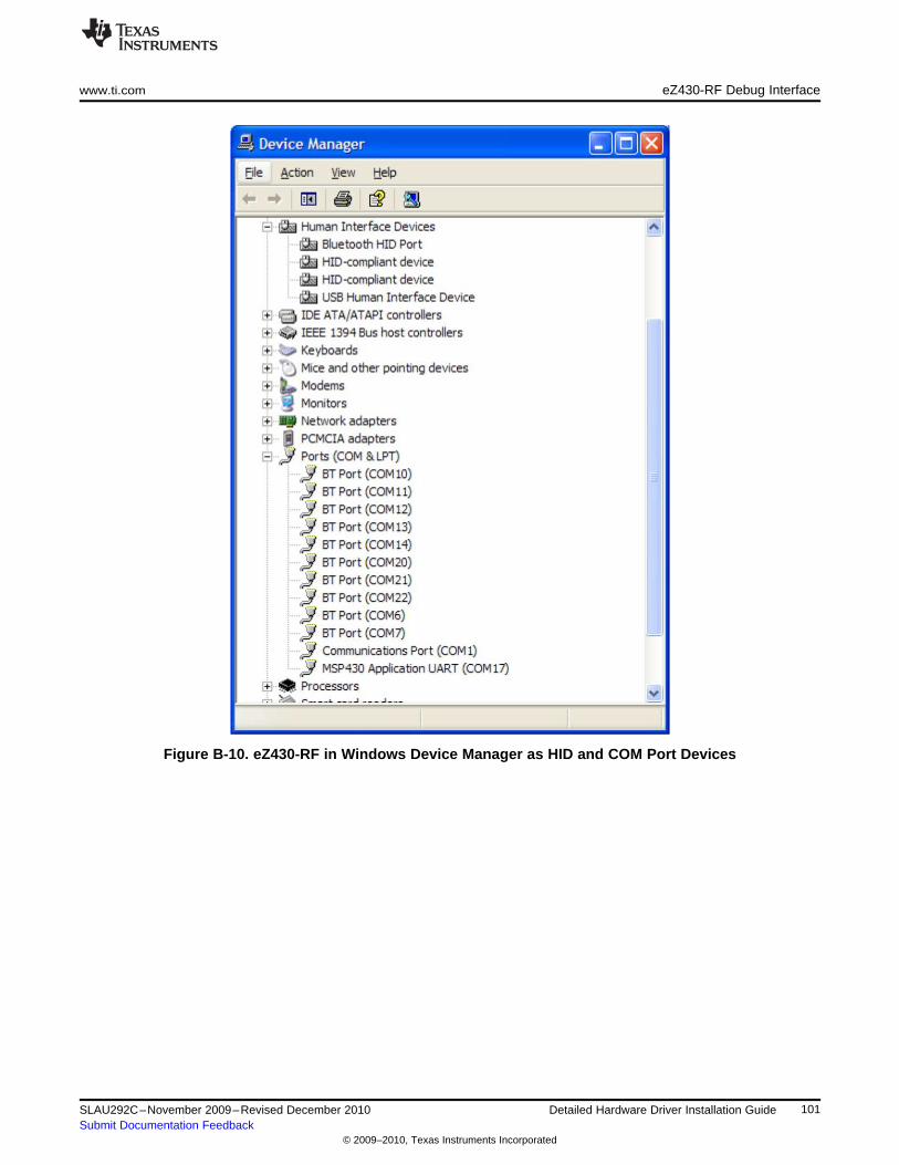
www.ti.com eZ430-RF Debug Interface
Figure B-10. eZ430-RF in Windows Device Manager as HID and COM Port Devices
101SLAU292C–November 2009–Revised December 2010 Detailed Hardware Driver Installation GuideSubmit Documentation Feedback
© 2009–2010, Texas Instruments Incorporated
IMPORTANT NOTICE
Texas Instruments Incorporated and its subsidiaries (TI) reserve the right to make corrections, modifications, enhancements, improvements,and other changes to its products and services at any time and to discontinue any product or service without notice. Customers shouldobtain the latest relevant information before placing orders and should verify that such information is current and complete. All products aresold subject to TI’s terms and conditions of sale supplied at the time of order acknowledgment.
TI warrants performance of its hardware products to the specifications applicable at the time of sale in accordance with TI’s standardwarranty. Testing and other quality control techniques are used to the extent TI deems necessary to support this warranty. Except wheremandated by government requirements, testing of all parameters of each product is not necessarily performed.
TI assumes no liability for applications assistance or customer product design. Customers are responsible for their products andapplications using TI components. To minimize the risks associated with customer products and applications, customers should provideadequate design and operating safeguards.
TI does not warrant or represent that any license, either express or implied, is granted under any TI patent right, copyright, mask work right,or other TI intellectual property right relating to any combination, machine, or process in which TI products or services are used. Informationpublished by TI regarding third-party products or services does not constitute a license from TI to use such products or services or awarranty or endorsement thereof. Use of such information may require a license from a third party under the patents or other intellectualproperty of the third party, or a license from TI under the patents or other intellectual property of TI.
Reproduction of TI information in TI data books or data sheets is permissible only if reproduction is without alteration and is accompaniedby all associated warranties, conditions, limitations, and notices. Reproduction of this information with alteration is an unfair and deceptivebusiness practice. TI is not responsible or liable for such altered documentation. Information of third parties may be subject to additionalrestrictions.
Resale of TI products or services with statements different from or beyond the parameters stated by TI for that product or service voids allexpress and any implied warranties for the associated TI product or service and is an unfair and deceptive business practice. TI is notresponsible or liable for any such statements.
TI products are not authorized for use in safety-critical applications (such as life support) where a failure of the TI product would reasonablybe expected to cause severe personal injury or death, unless officers of the parties have executed an agreement specifically governingsuch use. Buyers represent that they have all necessary expertise in the safety and regulatory ramifications of their applications, andacknowledge and agree that they are solely responsible for all legal, regulatory and safety-related requirements concerning their productsand any use of TI products in such safety-critical applications, notwithstanding any applications-related information or support that may beprovided by TI. Further, Buyers must fully indemnify TI and its representatives against any damages arising out of the use of TI products insuch safety-critical applications.
TI products are neither designed nor intended for use in military/aerospace applications or environments unless the TI products arespecifically designated by TI as military-grade or "enhanced plastic." Only products designated by TI as military-grade meet militaryspecifications. Buyers acknowledge and agree that any such use of TI products which TI has not designated as military-grade is solely atthe Buyer's risk, and that they are solely responsible for compliance with all legal and regulatory requirements in connection with such use.
TI products are neither designed nor intended for use in automotive applications or environments unless the specific TI products aredesignated by TI as compliant with ISO/TS 16949 requirements. Buyers acknowledge and agree that, if they use any non-designatedproducts in automotive applications, TI will not be responsible for any failure to meet such requirements.
Following are URLs where you can obtain information on other Texas Instruments products and application solutions:
Products Applications
Amplifiers amplifier.ti.com Audio www.ti.com/audio
Data Converters dataconverter.ti.com Automotive www.ti.com/automotive
DLP® Products www.dlp.com Communications and www.ti.com/communicationsTelecom
DSP dsp.ti.com Computers and www.ti.com/computersPeripherals
Clocks and Timers www.ti.com/clocks Consumer Electronics www.ti.com/consumer-apps
Interface interface.ti.com Energy www.ti.com/energy
Logic logic.ti.com Industrial www.ti.com/industrial
Power Mgmt power.ti.com Medical www.ti.com/medical
Microcontrollers microcontroller.ti.com Security www.ti.com/security
RFID www.ti-rfid.com Space, Avionics & www.ti.com/space-avionics-defenseDefense
RF/IF and ZigBee® Solutions www.ti.com/lprf Video and Imaging www.ti.com/video
Wireless www.ti.com/wireless-apps
Mailing Address: Texas Instruments, Post Office Box 655303, Dallas, Texas 75265Copyright © 2010, Texas Instruments Incorporated


