93
Ezetrol®plus Controller WT.050.425.001.GE.IM.0109
Ezetrol®plusController
WT.050.425.001.GE.IM.0109


Water Technologies
Chemfeed Limited, Priory Works, Tonbridge, Kent, TN11 0QL, England
Telephone Fax Internet
+44 (0) 1732 771777 +44 (0) 1732 771800 www.chemfeed.co.uk
IMPORTANT ANNOUNCEMENT Supply of Spares - Payment by Credit/Debit Card
Siemens Water Technologies are pleased to announce that we are now able to accept payment for spare parts by major credit/debit cards. We appreciate that some of our Customers periodically require quantities of spare parts, possibly to repair plant breakdowns. Standard procedures, whereby an official order has to be issued before parts can be supplied, often hinders this process, leaving the operations/maintenance personnel frustrated and without vital spares to complete the job. If you, or your staff, have a valid credit/debit card, that is all you need. We will not require an official order to cover credit/debit card transactions. To order freephone 0800 7834628. Our staff will take all the details and advise you on price and availability of your parts requirements. Your order will be despatched the same day wherever possible (depending on the time the order is placed). If ordered late in the day, it will be despatched the next working day. An invoice will be sent to your designated invoice address with a copy of the credit payment slip for your records. We are sure that this “Fast Track” facility will be welcomed by your “sharp end” personnel who keep plant operational. R. Russ General Manager Sales & Marketing


1Form RD1013 Issue 2 Dec 2003
Did we …… Excellent HighlySatisfactory Satisfactory Unsatisfactory Highly
Unsatisfactory
1 Treat you in a helpful & friendly manner? ¡ ¡ ¡ ¡ ¡
2 Provide sound advice, which demonstrates professionalism and knowledge of your application?
¡ ¡ ¡ ¡ ¡
3 Provide products and services that meet your range of chemical dosing & disinfection needs?
¡ ¡ ¡ ¡ ¡
4 Provide products and services of the quality that meets your needs?
¡ ¡ ¡ ¡ ¡
5 If we have recently supplied equipment to you, did it meet its stated performance?
¡ ¡ ¡ ¡ ¡
6 Provide a clear & easy to understand instruction manual?
¡ ¡ ¡ ¡ ¡
7 Give efficient, prompt service and keep you up to date on progress of your order?
¡ ¡ ¡ ¡ ¡
8 Act responsively and obligingly to your needs? ¡ ¡ ¡ ¡ ¡
9 Are we there when you need us – accessible and supportive?
¡ ¡ ¡ ¡ ¡
10 Did we take ownership of any problems you may have arisen?
¡ ¡ ¡ ¡ ¡
11 Overall how do you find our service? ¡ ¡ ¡ ¡ ¡
Much Better Better The same Worse Much Worse
12 Compared to 12 months ago, how do you rate our company’s performance?
¡ ¡ ¡ ¡ ¡
13 Compared to other equipment companies, how do you rate our service?
¡ ¡ ¡ ¡ ¡
Definitely Probably Might/might not
Probably not Definitely not
13 Would you recommend our company to your colleague? ¡ ¡ ¡ ¡ ¡
INSTRUCTION MANUAL - CUSTOMER FEEDBACK
Please help us to help you. As part of our commitment to providing the service you require, we are very interested to obtain your views of the current service we provide and any ideas for improvement. We want to deliver a service that is tailored to meet your needs, so we would be most grateful if you take a few moments to complete this feedback form.
We read every comment, good or bad, highlighted on returned questionnaires and will take the comments extremely seriously. The results will be reported to our management team as part of our quality procedures.
Would you please complete the form below. This will help us assess your responses accurately.
If you have any comments that that will help us improve our service, could you tell us what could have been done differently using the space in the appropriate sections.
WALLACE & TIERNAN STRANCO
2Form RD1013 Issue 2 Dec 2003
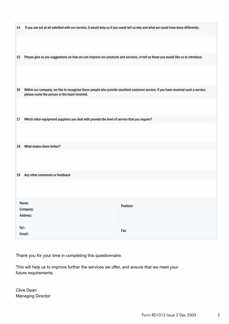
14 If you are not at all satisfied with our service, it would help us if you could tell us why and what we could have done differently.
15 Please give us you suggestions on how we can improve our products and services, or tell us those you would like us to introduce.
16 Within our company, we like to recognise those people who provide excellent customer service. If you have received such a service, please name the person or the team involved.
17 Which other equipment suppliers you deal with provide the level of service that you require?
18 What makes them better?
19 Any other comments or feedback
Thank you for your time in completing this questionnaire.
This will help us to improve further the services we offer, and ensure that we meet your future requirements.
Clive DeanManaging Director
Name: Company: Address:
Tel::Email:
Position:
Fax:
�WT.050.425.00�.GE.IM.0�09
Ezetrol®plus analysEr/controllEr
introduction
The Ezetrol® plus controller has been specifically designed for all types of swimming pools, spas and water features that are dosed with chlorine. The Ezetrol® plus controller is flexible in its approach to input options, offering parameters of free chlorine, pH and temperature as standard. Other parameter combinations such as dual chlorine inputs and pH measurement or the measurement of free chlorine, pH and redox are available. The Ezetrol® plus
This manual has been produced to enable the user to obtain maximum service from the equipment and comprises installation, operation maintenance and spare parts information. Minor changes may be made to the equipment that have been made, contact Siemens Water Technologies for information.
Our guarantee is conditional upon the equipment being used in accordance with the instructions herein and we therefore recommend that they be read and fully understood before the equipment is placed in service.
Siemens Water Technologies
contents
Target groups 1 Conventions 1.2
Safety 2 Intended use 2.1 General safety instructions 2.2 Safetyinstructionsspecifictotheunit 2.3 Description 3 Chlorinemeasurement 3.1 Disinfectionofwater 3.1.1 Rangeofapplications 3.1.2 Versions 3.2 Design 3.3 Overalldesign 3.3.1 Flowcellmodule 3.3.2 Electronicmodule 3.3.3 Functions 3.4 OverallFunction 3.4.1 Flowcellmodule 3.4.2 Electronicmodule 3.4.3 Safetyfunctions 3.4.4 Interfaces 3.4.5 Digitalinputs 3.4.6
WT.050.425.00�.GE.IM.0�092
Ezetrol®plus analysEr/conTrollEr
Controllertypes 3.4.7 Controlparameters 3.4.8 Alarms 3.4.9 Interfaces 3.4.10 TechnicalData 3.5 Electronicmodule 3.5.1 Flowcellmodule 3.5.2 Sensors 3.5.3
Installation 4 Versions 4.1 Transportandstorage 4.2 Transport 4.2.1 Storage 4.2.2 Installation 4.3 Transport 4.3.1 Unpacking 4.3.2 Location 4.3.3 Mounting 4.3.4 Samplewatersupply 4.3.5 Sensorconnection 4.3.6 Electricalconnection 4.3.7 Samplewaterdrainageline 4.3.8 Commissioning 4.4 Startingupprocedure 4.4.1 Fillingcellgrit 4.4.2 Insertthesensorsandconnect 4.4.3 ConnectingtheSampleWater 4.4.4Connectthedevicetothepowersupply 4.5 Connectingaflocculantpump 4.5.1 Switchtheuniton 4.5.2 Systemshutdown 4.6 Adaption 4.7 Settingsoverview 4.8
Operation 5 Displayandoperatorcontrols 5.1 Codenumber 5.1.1 Generalnotesonoperation 5.1.2 Menustructure 5.1.3 Operatingmodes 5.1.4 SwitchingtheEzetrol®plusoff 5.1.5 Switchingtheentiresystemoff 5.1.6 Calibration 5.2 Chlorinecalibration 5.2.1 pHcalibration 5.2.2 Redoxcalibration 5.2.3 Temperaturecalibration 5.2.4

�WT.050.425.00�.GE.IM.0�09
Ezetrol®plus analysEr/controllEr
Overfeedfailsafealarm 5.3 Errorsandremedies 5.4
Maintenance 6
Routinemaintenance 6.1 Daily 6.1.1 Weekly 6.1.2 Sixmonthly 6.1.3 Changingthefuse,battery,orMultiSensor 6.2 Replacingthefuse 6.2.1 Replacingthebattery 6.2.2 ChangingtheMultiSensor 6.2.3
Spareparts 7
Flowcellmoduleandsensors 7.1 Electronicmodule 7.2
Illustrations
Flowcellmodule(pressurised(AAC6100) Fig.1Backboardmountedunit(Drg.No.50235) Fig.2Wiringdiagrams(3sheetsDrg.No.50234) Fig.3

WT.050.425.00�.GE.IM.0�094
Ezetrol®plus analysEr/conTrollEr
1 target groups
Thisinstructionmanualprovidestheinformationforinstallation,operatingandmaintenancepersonnel.Itisintendedfortheoperatingpersonnel.It contains important information for safe, reliable, trouble-free andeconomicaloperationoftheunit.Observanceofthisinformationhelpstopreventdangerousincidents,lowersrepaircosts,reducesdown-times,andalsoincreasesthereliabilityandservicelifeoftheunit. Thechapter“Installation”isintendedfortrainedandqualifiedservicepersonnel only. It contains important information on installation,configurationandcommissioningoftheunit.
Allpersonsworkingwiththeunitmusthavereadandunderstoodtheinstructionmanual,particularlythesafetyinstructionsitcontains.

5WT.050.425.00�.GE.IM.0�09
Ezetrol®plus analysEr/controllEr
2 safety 2.1 intended use
TheEzetrol® plusisintendedexclusivelyforthecontrolofthetreatmentofwaterinswimmingpoolsspa'sandwaterfeaturesthataredosedwithchlorine.Itmayonlybeusedindoorsandundertheoperatingconditionsdescribedinthetechnicaldata.Theoperationalsafetyoftheunitisonlyguaranteedifitisusedinaccordancewithitsintendedapplicationasdefinedintheorderandundertheoperationalconditionsstatedinthetechnicalspecifications.
Compliancewiththeintendedusealsoincludesreadingthisoperatingmanualandobservingalltheinstructionsitcontains.Furthermore,allinspectionandmaintenanceworkmustbeperformedattheprescribedintervals.Theoperatorbearsfullandsoleresponsibilityifthisunitisputtoanyusewhichdoesnotcomplystrictlyandexclusivelywiththisintendeduse.
noTE: TheEzetrol® plus is not suitable for use with bromine based systems.
2.2 safety instructions
SiemensWaterTechnologies places great emphasis on safetywhenworkingonorwiththeunit.Thishasalreadybeentakenintoaccountinthedesignofthesystem,bytheintegrationofsafetyfeatures. Thesafetyinstructionsinthisdocumentationmustalwaysbeobserved.Thesedonotaffectthevalidityofanyadditionalnationalorcompanysafety instructions.
Allsafetyinstructionsattachedtotheunititselfmustbeobserved.Theymustalwaysbecompleteandeasilylegible. The unit has been constructed in accordancewith state-of-the-arttechnologyandtheacceptedsafetyregulations.However,iftheunitisusedbypersonswhohavenotbeenadequatelyinstructed,riskstolifeandlimbofsuchpersonsorthirdpartiesanddamagetotheunititselfortootherpropertycannotberuledout.Worknotdescribedinthisoperatingmanualmayonlybeperformedbyauthorisedpersonnel. Theoperatoroftheoverallsystemmustensurethatonlyauthorisedandqualifiedspecialistsarepermittedtoworkwithandontheunitwithintheirdefinedscopeofauthority.“Authorisedandspecialisedpersonnel”referstotrainedtechniciansemployedbytheoperator,SiemensWaterTechnologies or, if applicable, the service partner.Only qualifiedelectriciansmayperformworkonelectricalcomponents.

WT.050.425.00�.GE.IM.0�09�
Ezetrol®plus analysEr/conTrollEr
Trouble-freeoperationoftheunitisonlyguaranteediforiginalsparepartsandcomponentsareusedinpreciselythecombinationdescribedinthisinstructionmanual.Failuretoobservethisinstructionmayincurtheriskofmalfunctionordamagetotheunit.
Neverattempttoperformanymodifications,extensionsorconversionstotheunitthatcouldhaveanadverseaffectonsafetywithoutthewrittenapprovalofthemanufacturer.
Duringnormaloperation,thehousingmustremainclosed.
Priortoinstallation,inspection,maintenanceandrepairwork,alwaysswitchtheunitoffwiththemainswitchontheoutsideoftheunitandsecure against reactivation. Connectallcablesinaccordancewiththewiringdiagram. Ensure safe and environmentally-friendly disposal of agents andreplaced parts.
2.3 SafetyInstructionsSpecifictotheUnit
Thisinstructionmanualandthetechnicaldocumentationoftheinstalledcomponents of the unitmust always be available at the installationsite.
Alwaysobserveany supplementary,generallyvalid legal regulationsor other binding rules and ensure their compliance!These rules andregulations apply to:
• work safety • accident prevention • environmentalprotection• hygiene• first-aid All personnel chargedwith installation, commissioning, operation,maintenanceandrepairoftheunitmustreadandunderstandthisinstructionmanual,particularlythesafetyinstructions.
Neverattempttoperformanymodifications,extensionsorconversionsontheunitwhichcouldhaveanadverseaffectonsafetywithout thewrittenapprovalofthemanufacturer.
Onlyusesparepartswhichhavebeenapprovedbythemanufacturer.
�WT.050.425.00�.GE.IM.0�09
Ezetrol®plus analysEr/controllEr
Thisisalwaysguaranteedwhenoriginalsparepartsarepurchased.
Alwaysobservetheintervalsforregularmaintenanceorinspectionworkwhichareeitherprescribedorstatedintheinstructionmanual.
Thesystemmustnotbeusedwithflammableliquidsordangerousortoxic gases.
Neverusecorrosivecleaningagents!Useonlyadampclothtocleantheunit.
Alwaysreadtheinstructionmanual,inparticularthesafetyinstructions,beforeyouoperatetheunitforthefirsttime. Neveremployanyworkingmethodswhichcouldendangersafety!
Alwayscomplywiththeprescribedvaluesforsamplewateradmissionpressure, connection voltage as well as ambient and operatingconditions.
Neverdeactivateanysafetyfeatures. Duringoperationoftheunit,unexpectedincorrectfunctionsmayoccurthatresultfromfailureorerrorsinthecontrolsystem.Intheeventofsuchsafety-relevantchangesintheoperatingperformanceofthedevice,switch it off immediately and remedy the fault or have it remediedimmediately. Evenwhen the unit is switched off, external voltagemay still beapplied.
Always eliminate or have eliminated any leakageon theflowblockassemblyimmediately.
Intheeventofafire,alwaysswitchtheunitoffwiththemainswitchontheoutsideoftheunitorwiththeexternalmaincircuitbreakerorfuse.
WT.050.425.00�.GE.IM.0�09�
Ezetrol®plus analysEr/conTrollEr
3 description 3.1 ChlorineMeasurement3.1.1 disinfection of water
Swimming poolwater is generally disinfected by adding calciumhypochloriteorsodiumhypochlorite.Accuratedosingofthesechemicalsis extremely important because the degree of disinfectionmay beinsufficientiftheconcentrationistoolow.Ontheotherhand,iftheirconcentrationistoohigh,theremaybeanoticeablechangeintheodourorevencorrosivedamagetothepool.
3.1.2Rangeofapplications
Continuousmeasurement
• oftheconcentrationofchlorinedisinfectant • ofthepHvalue • oftheredoxvoltage • controlofdosingunits toautomatically regulate theamountof
disinfectantinthewaterandthepHvalue.
TheEzetrol® pluscomplieswiththefollowingstandards:
• DIN19643“Treatmentofwaterofswimming-poolsandbaths”and
• ÖNORMM5872Equipmentofwatertreatmentplantsforswimmingpoolswithmeasuringandcontrolinstruments.
and• PWTAG-SwimmingPoolWaterTreatmentandQualityStandards
noTE: Wedonot recommend thatEzetrol®plus isused tocontrolBromine

9WT.050.425.00�.GE.IM.0�09
Ezetrol®plus analysEr/controllEr
3.2 Versions
ThefollowingversionsoftheEzetrol® plusareavailable:
• WithchlorineandpHmeasurementandcontrol• With chlorine and pH measurement and control and redox
measurement • For200–240VAC • withthreemAoutputs • Pre-mountedonauPVCboard(PartNoAAA1791)
• With2xmeasurementandcontrol, pHmeasurementandcontrolforacommoncircuitboard
3.3 design 3.3.1 Overalldesign
TheEzetrol® plusisamodularsystem.
The twomain components are theflowblock assembly (A) and theelectronicsmodule(C).
Upto3sensors(B)canbeinstalledintheflowblockassembly.
A B C
A Flow cell module B Sensors C Electronic module

WT.050.425.00�.GE.IM.0�09�0
Ezetrol®plus analysEr/conTrollEr
3.3.2 Flowcellmodule
Theflowcellmodulehasaplastichousing(B)witharemovablecover.Allthecomponentsoftheflowcellmoduleareinstalledinthishousing:
• Flowcontrolvalve(C)• TheMultiSensorformonitoringtemperatureandflowrate(F)• Thedrain(D)• Thesamplewaterinletwithcheckvalveandballvalve(E)• Thesamplewateroutlet(D)withballvalve
Thetopclips(H)forthesensorandthelowerclips(G)toholdthebufferorcalibrationsolutioncanbemountedontheoutsideofthehousing.
Twoseatsareprovidedforthelowerclips.Thecellbodycanbeequippedwithamaximumof3sensors(I).TheEzetrol® plus-flowcellmoduleis always pressurised.
I
H
A
G B
F
E C D
A PlastichousingB Flow control valveC SamplewateroutletD DrainE Ball valveF Multi sensorG Lower clipH Upper clipI Sensors
��WT.050.425.00�.GE.IM.0�09
Ezetrol®plus analysEr/controllEr
A
B
C
D
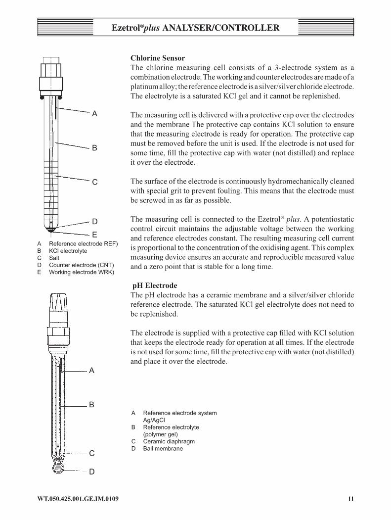
EA ReferenceelectrodeREF)B KClelectrolyteC SaltD Counterelectrode(CNT)E WorkingelectrodeWRK)
A Referenceelectrodesystem Ag/AgClB Referenceelectrolyte (polymergel)C CeramicdiaphragmD Ballmembrane
A
B
C
D
chlorine sensorThe chlorinemeasuring cell consists of a 3-electrode system as acombinationelectrode.Theworkingandcounterelectrodesaremadeofaplatinumalloy;thereferenceelectrodeisasilver/silverchlorideelectrode.TheelectrolyteisasaturatedKClgelanditcannotbereplenished.
ThemeasuringcellisdeliveredwithaprotectivecapovertheelectrodesandthemembraneTheprotectivecapcontainsKClsolutiontoensurethatthemeasuringelectrodeisreadyforoperation.Theprotectivecapmustberemovedbeforetheunitisused.Iftheelectrodeisnotusedforsometime,filltheprotectivecapwithwater(notdistilled)andreplaceitovertheelectrode.
Thesurfaceoftheelectrodeiscontinuouslyhydromechanicallycleanedwithspecialgrittopreventfouling.Thismeansthattheelectrodemustbescrewedinasfaraspossible.
ThemeasuringcellisconnectedtotheEzetrol® plus. A potentiostatic control circuitmaintains the adjustablevoltagebetween theworkingandreferenceelectrodesconstant.Theresultingmeasuringcellcurrentisproportionaltotheconcentrationoftheoxidisingagent.Thiscomplexmeasuringdeviceensuresanaccurateandreproduciblemeasuredvalueandazeropointthatisstableforalongtime.
pH ElectrodeThepHelectrodehasaceramicmembraneandasilver/silverchloridereferenceelectrode.ThesaturatedKClgelelectrolytedoesnotneedtobereplenished.
TheelectrodeissuppliedwithaprotectivecapfilledwithKClsolutionthatkeepstheelectrodereadyforoperationatalltimes.Iftheelectrodeisnotusedforsometime,filltheprotectivecapwithwater(notdistilled)andplaceitovertheelectrode.
WT.050.425.00�.GE.IM.0�09�2
Ezetrol®plus analysEr/conTrollEr
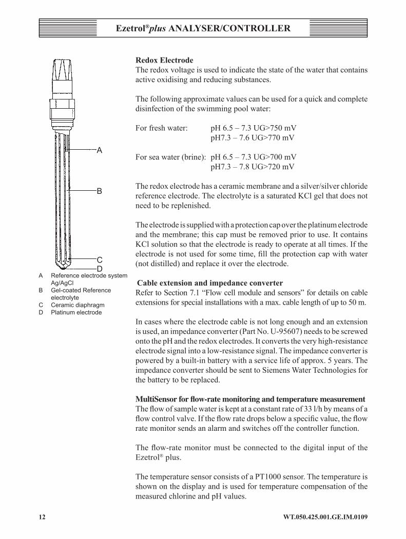
redox ElectrodeTheredoxvoltageisusedtoindicatethestateofthewaterthatcontainsactiveoxidisingandreducingsubstances.
Thefollowingapproximatevaluescanbeusedforaquickandcompletedisinfectionoftheswimmingpoolwater:
Forfreshwater: pH6.5–7.3UG>750mV pH7.3–7.6UG>770mV
Forseawater(brine):pH6.5–7.3UG>700mV pH7.3–7.8UG>720mV
Theredoxelectrodehasaceramicmembraneandasilver/silverchloridereferenceelectrode.TheelectrolyteisasaturatedKClgelthatdoesnotneedtobereplenished. Theelectrodeissuppliedwithaprotectioncapovertheplatinumelectrodeandthemembrane;thiscapmustberemovedpriortouse.ItcontainsKClsolutionsothattheelectrodeisreadytooperateatalltimes.Iftheelectrodeisnotusedforsometime,filltheprotectioncapwithwater(notdistilled)andreplaceitovertheelectrode.
cable extension and impedance converter RefertoSection7.1“Flowcellmoduleandsensors”fordetailsoncableextensionsforspecialinstallationswithamax.cablelengthofupto50m.
Incaseswheretheelectrodecableisnotlongenoughandanextensionisused,animpedanceconverter(PartNo.U-95607)needstobescrewedontothepHandtheredoxelectrodes.Itconvertstheveryhigh-resistanceelectrodesignalintoalow-resistancesignal.Theimpedanceconverterispoweredbyabuilt-inbatterywithaservicelifeofapprox.5years.TheimpedanceconvertershouldbesenttoSiemensWaterTechnologiesforthebatterytobereplaced.
Multisensor for flow-rate monitoring and temperature measurementTheflowofsamplewateriskeptataconstantrateof33l/hbymeansofaflowcontrolvalve.Iftheflowratedropsbelowaspecificvalue,theflowratemonitorsendsanalarmandswitchesoffthecontrollerfunction.
Theflow-ratemonitormustbeconnected to thedigital inputof theEzetrol® plus. ThetemperaturesensorconsistsofaPT1000sensor.ThetemperatureisshownonthedisplayandisusedfortemperaturecompensationofthemeasuredchlorineandpHvalues.
A Referenceelectrodesystem Ag/AgClB Gel-coatedReference electrolyteC CeramicdiaphragmD Platinumelectrode
A
B
CD
��WT.050.425.00�.GE.IM.0�09
Ezetrol®plus analysEr/controllEr
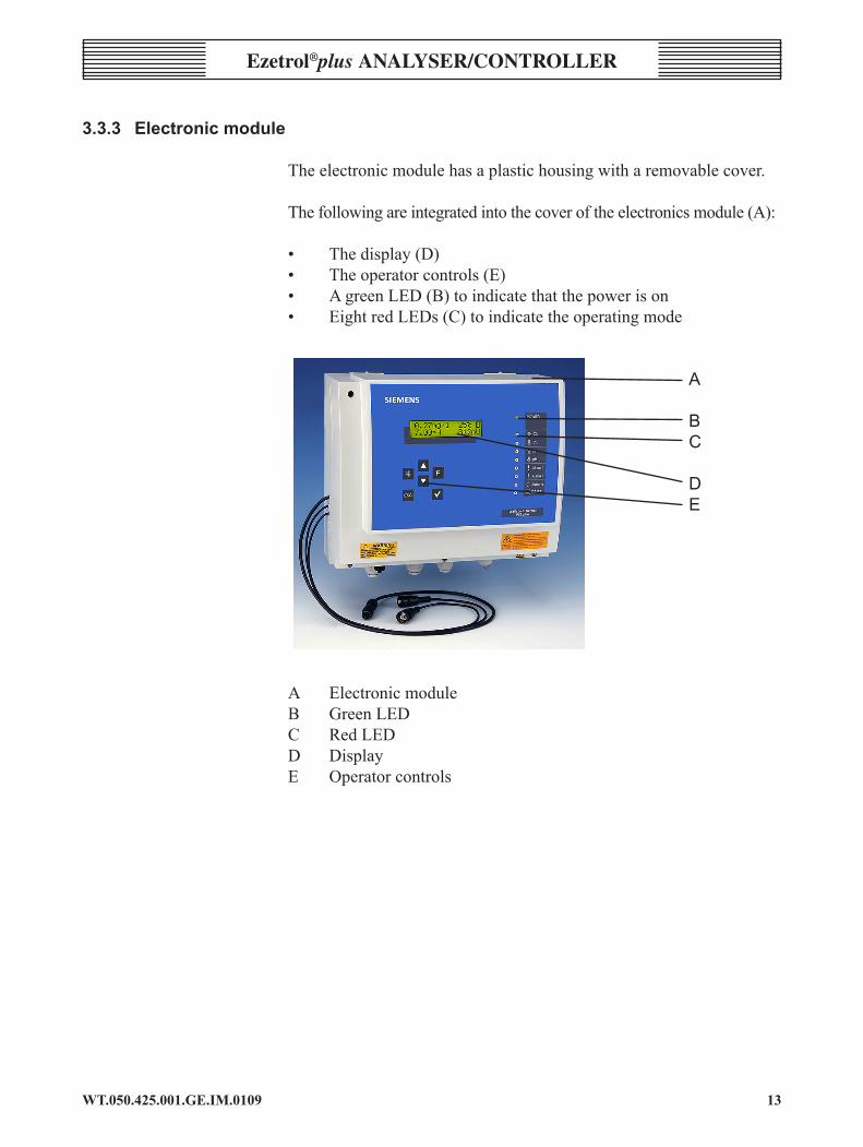
3.3.3 Electronicmodule
Theelectronicmodulehasaplastichousingwitharemovablecover.
Thefollowingareintegratedintothecoveroftheelectronicsmodule(A):
• Thedisplay(D)• Theoperatorcontrols(E)• AgreenLED(B)toindicatethatthepowerison• EightredLEDs(C)toindicatetheoperatingmode
A
B C
D E
A ElectronicmoduleB Green LEDC Red LEDD DisplayE Operator controls

WT.050.425.00�.GE.IM.0�09�4
Ezetrol®plus analysEr/conTrollEr
Theelectronicmoduleconsistsof:
• Motherboardwithpowerunit,RS485interface• Bufferbatteryfortheclock(A)• ConnectionforthepHmeasuringcell(B)• Connectionsforthechlorineandredoxmeasuringcells(C)• Therelayandtheterminalstripfortheoutputs(D)• Thehousingductsforthesensorcable(E)
A BufferbatteryfortheclockB ConnectionforthepHmeasuringcellC ConnectionsforthechlorineandredoxmeasuringcellsD RelayandterminalstripsforoutputsE HousingductsforthesensorcableFRS232interfaceG Cableglands
Thefollowingareincorporatedintothebaseofthehousing:
• TheRS232interface(F)• Thecableterminalscrews(G)
3.4 functions 3.4.1 OverallFunction
Up to fourmeasured values can be indicated by process-adjustedcomponents:
• Freechlorine• pH value • Redoxvoltage(optional)• Temperature

�5WT.050.425.00�.GE.IM.0�09
Ezetrol®plus analysEr/controllEr
Numericalvaluesofthemeasureddata,limitvaluesandsetpointvaluesareshownonthedisplay.Allmeasuredvaluescanbedisplayedatthesametime.
3.4.2 Flowcellmodule
Theflowblockassemblyguarantees a stablemeasurement signalonaccount of:
• robustsensors• constantflowrateofsamplewaterwiththeaidoftheflowcontrolvalve• hydrodynamiccleaningofthemeasuringelectrodesofthechlorine
sensorwithsand• optimumflowaroundallsensors
Themulti-sensorintegratedintotheflowblockassemblymonitorstheconstant flow rate of samplewater, registers the temperature of thesamplewaterandensuresequipotential earthingovera large surfacearea(samplewaterearthing).
3.4.3 Electronicmodule
Theelectronicmoduleisusedforvisualisationandsubsequentprocessingofthemeasureddataaswellasprocesscontrol.Positionersorvariousdosingpumpscanbeconnectedtothecontroloutputsoftheprocesscontrolunit.
Thefollowingfunctionsarepossible:
• Dosing of disinfectant • CorrectionofthepHvalue• Additionofflocculantwithlockingofthecirculationsystem
Uptotworelayoutputscanalsobeusedasalarmcontacts.Theycanbefreelyconfigured.Multipleallocationofeventsispossible.Theadaptionprogramautomatically determines the control parameters for dosingchlorineduringstart-up.
3.4.4 safety functions
Thesafetyfunctionsintegratedintothecontrolunitare:
• safetyshutdownifthereisnoflowofsamplewater• safetyshutdownifthecirculationfails• safetyshutdownifthesupplycontainersignalsitisempty• monitoringofthedosingtime• dosing delay

WT.050.425.00�.GE.IM.0�09��
Ezetrol®plus analysEr/conTrollEr
• alarmsandcommonalarms• Errormessage• Password protection
3.4.5 interfaces
TheEzetrol®plussupportsthefollowingadd-ons:
• CMS:VisualisationsoftwareforarchivinganddisplayofmeasuredvaluesoncomputerswithaWindowsoperatingsystem
• SECO-S7:PLCdriverfordatalinkstoSiemensPLC,typeS7-300• OPC-Server DataAccess V2.0: Server software for Windows
operatingsystemsfordatalinkstovisualisationsystemwithOPCclientcapability
• ChemWeb-Server: Archiving and display of measured values,remotediagnosis,remoteaccesswithstandardbrowserwithinternetande-mailcapabilities
• Processcontrolsystemsfromothermanufacturers.
3.4.6Digitalinputs
WarnInG:Thedigitalinputsaredesignedforvoltage-freeexternalcontacts.Externalvoltagesmaydamageelectricalcircuits. Digital input DI TheDIcontactfortheflowswitchontheflowcellallowsthedosingtobestoppedandthealarmenabled.
• Beforethedelaytimehasexpired,samplewatermonitoring(0tomax.10min.):ThedosingpumpforchlorineandthedosingpumpforthepHcorrectionmediumcontinuerunningatthesamerate.TheDIsymbolinthedisplayflashes.Display:DI*samplewater?
• Afterexpiryofthedelaytimeofthesamplewatermonitor:thedosing pump for chlorine dosing and the dosing relay for pHcorrectionareswitchedoff.Display:DI*samplewater?
This controller shutdown function is only active in automatic mode.
Digital input DII TheDII contact is normally used as the circulation pump interlock,allowingthecontrollertobestoppedimmediatelywhenthecirculationpumpsareelectricallyisolated.
• ThedosingpumpforchlorineandthedosingpumpforpHcorrectionareswitchedoff.
��WT.050.425.00�.GE.IM.0�09
Ezetrol®plus analysEr/controllEr
Display:DII*ext.STOP? Whenthestandbyfunctionisswitchedon,display:STANDBY.
This controller shutdown function is only active in automatic mode.
Digital input DIII• TheDIII contactisgenerallyusedtoindicatethatthechemical
tankisempty. Thedosingpumpforchlorineand thedosingpumpfor thepH
correctionareswitchedoff. Display:DIII*Carboy?
This controller shutdown function is only active in automatic mode.
noTE:Oncethecontacthasbeenre-establishedtheremaybeadelayinrestartingthecontrollerduetothedosingdelay.ThedigitalinputsDIIandDIIIaredeactivatedondelivery(fittedwithjumpers).Toactivatethefunction,removethejumpersandconnectoneexternalcontacttoeachinput.
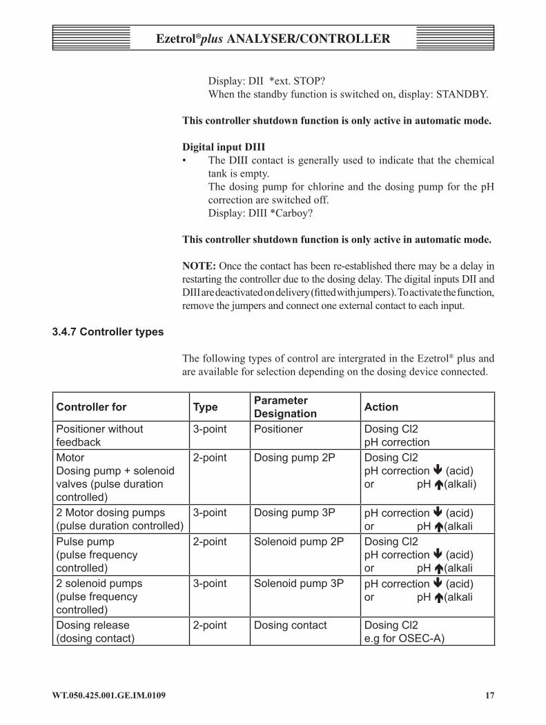
3.4.7Controllertypes
ThefollowingtypesofcontrolareintergratedintheEzetrol® plus and areavailableforselectiondependingonthedosingdeviceconnected.
Controllerfor type Parameterdesignation action
Positionerwithoutfeedback
3-point Positioner DosingCl2pHcorrection
MotorDosingpump+solenoidvalves(pulsedurationcontrolled)
2-point Dosingpump2P DosingCl2pHcorrectionä(acid)orpHã(alkali)
2Motordosingpumps(pulsedurationcontrolled)
3-point Dosingpump3P pHcorrectionä(acid)orpHã(alkali
Pulsepump(pulsefrequencycontrolled)
2-point Solenoidpump2P DosingCl2pHcorrectionä(acid)orpHã(alkali
2solenoidpumps(pulsefrequencycontrolled)
3-point Solenoidpump3P pHcorrectionä(acid)orpHã(alkali
Dosingrelease(dosingcontact)
2-point Dosingcontact DosingCl2e.gforOSEC-A)

WT.050.425.00�.GE.IM.0�09��
Ezetrol®plus analysEr/conTrollEr
Positioner(withoutfeedback)Usingtheintegratedcontroller,itispossibletoimplementfeedcontrolincombinationwithapositionerasanactuator.Dependingonthecontroldeviation,thepositionercancontrolthequantityofgasfed,e.g.usingtheV10kgasfeeder.
Thecontroldirection(controlofthepositioner)isindicatedbytheLEDinthedisplayfield.
Dosingofchlorinegasisincreased
Dosingofchlorinegasisdecreased
Dosing of CO2 gas is increased
Dosing of CO2 gas is decreased
In'Manual'mode('Cl2actuator'or'pHactuator'menu)thepositionercanbeopenedandclosedbypressingthes and t keys
noTE:IntheeventofapowerfailureanypositionersconnectedtotheEzetrol®plusarenolongeractuatedandstopmoving.Thisdoesnotinterruptthegasfeed.Thismayresultinadangerousoverdosingofchlorine.
Toensurethatanypositionersconnectedautomaticallyshutdownto0%connectanexternalphasetoterminal53(forchlorine)or47(forpH).Thisensures that if thepower to theEzetrol® plus fails, this external phase switches the relay so that the positioner closes until it reaches the end position at 0%.
Pulse duration controller for dosing pumps The dosing pump is switched on for the calculated timewithin anadjustablecycleperiodTp(relaycontact).ThecycleperiodismainlydeterminedbythereactiontimeoftheconnectedsystemandenteredasthecycleperiodTp. Example: cycleperiodTp 100s OutputvalueYout 30% Dutycycle 30s Off-dutycycle 70s

�9WT.050.425.00�.GE.IM.0�09
Ezetrol®plus analysEr/controllEr
Pulse-frequency controller for solenoid pumpsSolenoidpumpsarecontrolledwith0to100or0to120pulsesperminute,dependingonthespecificationoftheconnectedpump.
Thedutycycleduringeachdoseis0.3s.Thebreaktimeiscalculatedtobebetween0.2and60sdependingonthedosingrate.
Example:-Forapulsepumpwith120pulses/min.
Youtin% 100 84 72 56 50 33 25 10 5 1 0Pulses/min 120 96 85 75 60 40 30 12 6 1 0
Manual actuation of a dosing pump or a solenoid valve1 Press ttoaccessthe“Mode”menu.2 Press 3,“>Mode”isdisplayed.3 Presstuntil“Manual”isdisplayed.4 Confirmbypressing3. 5 Pressttoaccessthe“pHactuator”menu(orsimilarlytoaccess
the“Cl2actuator”menu).6 Press3,“>OFF”,“pH+”or“pH-”isdisplayed. Toswitchonthedosingpump:Presss. Toswitchoffthedosingpump:Presst.
Cl2dosingpumprunning
“IncreasepH“dosingpumprunning
“DecreasepH”dosingpumprunning 2-point pulse duration controller for dosing pump and 2-point pulse frequency controller for pulse pumpOnedosingpumpisusedtodecreasethepHvalue(dosingofacid),theotherdosingpumpisusedtoincreasethepHvalue(dosingofalkali).
Thistypeofcontrollerisusedifonlyonepumpisconnected(acidoralkali).Thecontroldirection(pH+orpH-)mustbecorrectlyselected.

WT.050.425.00�.GE.IM.0�0920
Ezetrol®plus analysEr/conTrollEr
ControldirectionpH+(alkali) ControldirectionpH+(acid)
Ifthecurrentvalue>setpointthepumpisnot Ifthecurrentvalue<setpointthepumpisnotactuated. actuated.
TheactuationstatusofthedosingpumpsisindicatedbytheLEDsonthedisplay:
'IncreasepH'dosingpumprunning(pH+/alkali)
'DecreasepH'dosingpumprunning(pH+/acid)
�-point pulse duration controller for dosing pump and �-point pulse frequency controller for pulse pump OnedosingpumpisusedtodecreasethepHvalue(dosingofacid),theotherdosingpumpisusedtoincreasethepHvalue(dosingofalkali).
Ifthesetpoint=actualvalue,nopumpisactivated(neutralzoneXsh).
Thecontrolrangeis0to+100%and0to-100%.
� � � �� �� � � � �
� � � �
� � � � � � � � � � � � �
� � � � � � � � � � �
�� � � � � � � �� � � � � �
� � � � �

2�WT.050.425.00�.GE.IM.0�09
Ezetrol®plus analysEr/controllEr
Thecontroldirection(controlofthedosingpumps)isindicatedbytheLEDsinthedisplayfield:
'Increase'pHdosingpumprunning(pH+/alkali)
'Decrease'pHdosingpumprunning(pH+/acid)
Dosing contact e.g. for osEc-aA special controller is required for controlling electrolysis units topreventexcessiveon/offswitching(onaccountoftheresponsetimesoftheelectrolysisunit).
Thiscontrolleroutput,therefore,usesaminimumdutycycleaswellasaswitchinghysteresistominimisetheswitchingcycles.
IfthevaluefallsbelowthespecifiedCl2setpointminushysteresis(e.g.setpoint0.50mg/l -hysteresis0.05=0.45mg/l), thecontrolleroutputswitcheson.
Thecontrolleroutputremainsactiveforatleastthesetminimumdutycycle.Ifthesetpointisexceededandtheminimumdutycyclehasexpiredthecontactswitchesoff.
Theminimumdutycycleisignoredinthemanualmode.
3.4.8 Controlparameters
Controlparametersareinputvariablesthatdeterminethecontrolfunctionsofacontroller.Differentparametersapplytoeachtypeofcontroller.
max. pulse/minThemax. pulses/min parameter only applies to pulse pumps.Thisparameterisusedtosetthemaximumnumberofpulsesperminuteinaccordancewiththepumpused.
Setting range:Thepulsesmax./minparametercanbesettoeither100or120pulses.
setpointThespecifiedvalueatwhichthecontrolparameter(chlorine,pH)istobemaintainedbythecontroller.
Setting range:Inaccordancewiththecorrespondingmeasuringrange.
WT.050.425.00�.GE.IM.0�0922
Ezetrol®plus analysEr/conTrollEr
Tn On the basis of the integral action timeTn, the dosing rate changesconstantlyuntilthesetpointisreached.ThehigherthevalueofTn,thelongerittakesuntilthecontrollerincreasesthedosingrate.
Tnhigher:ControlresponseisslowerTn lower: Control response is faster
Setting range: TheparameterTncanbebetween0–100min(Tn=0meansthatthe'I-element'isdeactivated,i.e.apureP-controlresponseapplies).Itmaynotbepossibletoreachthesetpointvalue.
IfusingapositionercontrolleritisimpossibletosetTnto0(off).
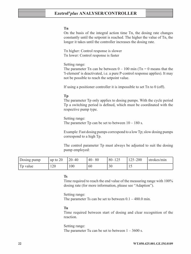
TpTheparameterTponlyappliestodosingpumps.WiththecycleperiodTpaswitchingperiodisdefined,whichmustbecoordinatedwiththerespectivepumptype.
Setting range:TheparameterTpcanbesettobetween10–180s.
Example:FastdosingpumpscorrespondtoalowTp;slowdosingpumpscorrespondtoahighTp. ThecontrolparameterTpmustalwaysbeadjustedtosuit thedosingpumpemployed:
Dosingpump upto20 20–40 40–80 80–125 125–200 strokes/min
Tp value 120 100 60 30 15
TsTimerequiredtoreachtheendvalueofthemeasuringrangewith100%dosingrate(formoreinformation,pleasesee“Adaption”).
Setting range:TheparameterTscanbesettobetween0.1–480.0min.
Tu Time required between start of dosing and clear recognition of thereaction.
Setting range: TheparameterTucanbesettobetween1–3600s.
2�WT.050.425.00�.GE.IM.0�09
Ezetrol®plus analysEr/controllEr
noTE: If the valuesTu andTs aremanuallymodified, the controlparametersXpandTnarere-calculated.
Ty TheparameterTyonlyappliestopositioners.Tyisthetimewhichthepositionerrequirestoadjustfrom0%to100%.
Setting range:TheparameterTycanbesetfrom10–180s.
Xp Thecontrolamplificationisdeterminedbymeansoftheproportionalfactor.ThelowertheproportionalfactorXpisselectedin%,thegreaterthedeviationfromthesetpointisamplified,andthemorequicklythecontrollerattemptstocontrolthedeviationfromthesetpoint. The control amplification factor is calculated using the followingequation:
Factor=(1/Xp)x100%
Settingrange:TheparameterXpcanbesettobetween1%(factor100)–1000%(factor0.1). HysteresisThehysteresisparameteronlyappliesto3-pointcontrollersandthedosingcontact.Thereisnocontrolleroutputintheneutralzone.
Setting range: 0.01-0.50mg/l(Cl2)0.01-0.50pH(pH)
control directionThecontroldirectioncanonlysetfor2-pointcontrollersandpositionersfor pH correction.
Setting range: pH+orpH-
min. on time Theparametermin.ONtimeonlyappliesfordosingcontactanddefinestheminimumdutycyclefordosing.
Settingrange:1-120min
WT.050.425.00�.GE.IM.0�0924
Ezetrol®plus analysEr/conTrollEr
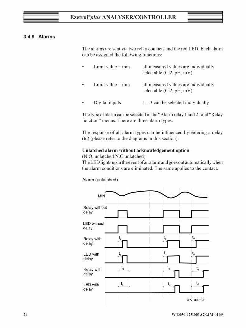
3.4.9 Alarms
ThealarmsaresentviatworelaycontactsandtheredLED.Eachalarmcanbeassignedthefollowingfunctions:
• Limitvalue=min allmeasuredvaluesareindividually selectable(Cl2,pH,mV)
• Limitvalue=min allmeasuredvaluesareindividually selectable(Cl2,pH,mV)
• Digitalinputs 1–3canbeselectedindividually
Thetypeofalarmcanbeselectedinthe“Alarmrelay1and2”and“Relayfunction“menus.Therearethreealarmtypes. Theresponseofallalarmtypescanbeinfluencedbyenteringadelay(td)(pleaserefertothediagramsinthissection).
Unlatched alarm without acknowledgement option(N.O. unlatched N.C unlatched) TheLEDlightsupintheeventofanalarmandgoesoutautomaticallywhenthealarmconditionsareeliminated.Thesameappliestothecontact.
� � �
� � � � � � � � � � � � � �
� � � � �
� � � � � � � � � � � �
� � � � �
� � � � � � � � � �
� � � � �
� � � � � � � � �
� � � � �
� � � � � � � � � � �
� � � � �
� � � � � � � � �
� � � � �
� � � � � � � � �
� � � � � � � � � � � � � � � � �
��
��
��
��
��
��
��
�� �
�
��
��
��
25WT.050.425.00�.GE.IM.0�09
Ezetrol®plus analysEr/controllEr
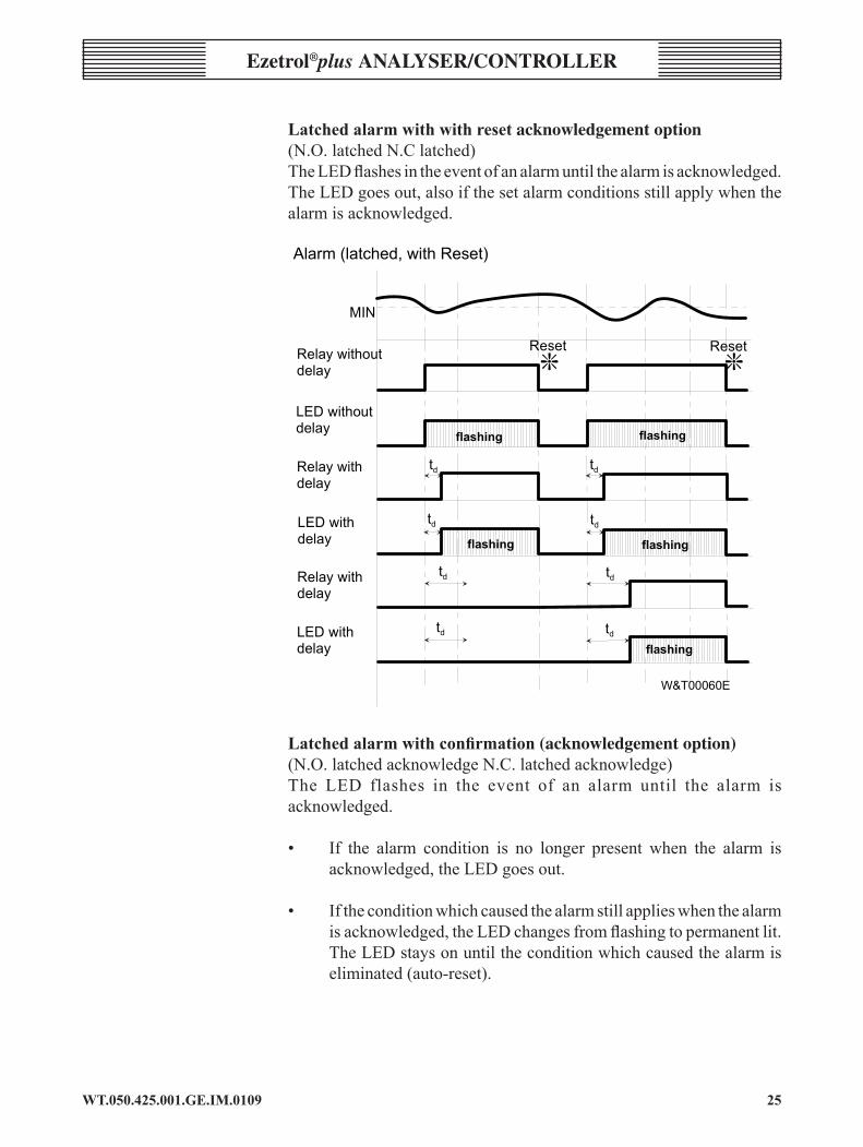
latched alarm with with reset acknowledgement option(N.O.latchedN.Clatched)TheLEDflashesintheeventofanalarmuntilthealarmisacknowledged.TheLEDgoesout,alsoifthesetalarmconditionsstillapplywhenthealarmisacknowledged.
� � �
� � � � � � � � � � � � � �
� � � � �
� � � � � � � � � � � �
� � � � �
� � � � � � � � � �
� � � � �
� � � � � � � � �
� � � � �
��
� � � � �
� � � � � � � �
� � � � � � � � � � �
� � � � �
� � � � � � � �
� � � � �
� � � � �
��
��
��
��
��
��
��
� � � � � � � �
� � � � � � � �
� � � � � � � �
� � � � � � � �
� � � � � � � � �
� � � � � � � � � � � � � � � � � � � � � � � � � � �
� �
Latched alarm with confirmation (acknowledgement option)(N.O.latchedacknowledgeN.C.latchedacknowledge)The LED flashes in the event of an alarm until the alarm isacknowledged.
• If the alarm condition is no longer present when the alarm is
acknowledged,theLEDgoesout.
• Iftheconditionwhichcausedthealarmstillapplieswhenthealarmisacknowledged,theLEDchangesfromflashingtopermanentlit.TheLEDstaysonuntiltheconditionwhichcausedthealarmiseliminated(auto-reset).

WT.050.425.00�.GE.IM.0�092�
Ezetrol®plus analysEr/conTrollEr
� � �
� � � � � � � � � � � � � �
� � � � �
� � � � � � � � � � � �
� � � � �
� � � � � � � � � �
� � � � �
� � � � � � � � �
� � � � �
� � � � � � � � � � �
� � � � �
� � � � � � � � �
� � � � �
� � � � � � �
� � � �
� � � �
� � � � �
� � � � � � � � � � � � � � � � � � � � � � � � � � � � � � � � � �
� � � � � � �
� � � �
� � � � � � �
� � � �
� � � � � � � �� � � � � � � �
� � � � � � � � � � � � � � � �
� � � � � � � �
��
��
��
��
��
� � � � � � � �
��
��
��
�
�
3.4.10 interfaces
Two interfaces are available formaking external connections to theEzetrol®plus.
rs2�2 TheRS232interfaceisusedtoconnectaprinter
SpecificationoftheRS232interfaceforprinteroperation:
• Datatransfer9600baud• Paritystraight• Lengthofword8bit
Anoperatinglogisprintedforeachdayofoperation(seebelow).
Eachdailylogconsistsofalogheader,trendgraphsandtheoutputofthedailymin.andmax.values.
Theavailablemeasurementsandthecorrespondingparameters,suchasthesetpoint,XpandTn,areprintedinthelogheader.Thedateofthelastcalibrationisalsodocumented.

2�WT.050.425.00�.GE.IM.0�09
Ezetrol®plus analysEr/controllEr
Thisisfollowedbyaprintoutofthetrendgraphs,includingthemeasuringrangesandthecurrentoperatingmode,asabargraph.Thetrendgraphsarerecordedatone-minuteintervals.
Thecalibrationtimesforeachmeasurementareprintedat theendofthelog.
Printer log
noTE: Themaximumcablelengthbetweentheinterfaceandtheprintermustnotexceed15m.
Toprint logs,SiemensWaterTechnologiesofferaRS232logprinter(AAC5995)aswellasaprinterconnectingcable,3m(AAC5887)or15m(AAC5914)long,asaccessories.Setupinstructionsareprovidedwiththeprinter(FAE1208). noTE:InformationontheRS485interfacecanberequestedseparatelyfromSiemensWaterTechnologies.
IfaRS485logprinterfromWallace&Tiernan(AAB9187)isalreadyavailable (e.g. fromaprevious system), it canstillbeusedwith thissystembyconnectingittotheRS485interface.
WT.050.425.00�.GE.IM.0�092�
Ezetrol®plus analysEr/conTrollEr
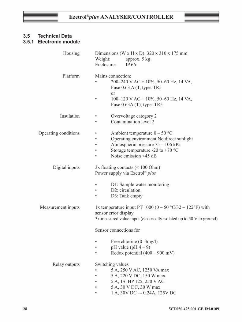
3.5 TechnicalData3.5.1 Electronicmodule
Housing Dimensions(WxHxD):320x310x175mm Weight: approx.5kg Enclosure: IP66
Platform Mainsconnection: • 200–240VAC±10%,50–60Hz,14VA, Fuse0.63A(T,type:TR5 or • 100–120VAC±10%,50–60Hz,14VA, Fuse0.63A(T),type:TR5
Insulation • Overvoltage category 2 • Contaminationlevel2
Operatingconditions • Ambienttemperature0–50°C • OperatingenvironmentNodirectsunlight • Atmosphericpressure75–106kPa • Storagetemperature-20to+70°C • Noiseemission<45dB
Digitalinputs 3xfloatingcontacts(<100Ohm) PowersupplyviaEzetrol® plus • D1:Samplewatermonitoring • D2: circulation • D3:Tankempty
Measurementinputs 1xtemperatureinputPT1000(0–50°C/32–122°F)with sensor error display 3xmeasuredvalueinput(electricallyisolatedupto50Vtoground) Sensor connections for
• Freechlorine(0–3mg/l) • pHvalue(pH4–9) • Redoxpotential(400–900mV)
Relayoutputs Switchingvalues • 5A,250VAC,1250VAmax • 5A,220VDC,150Wmax • 5A,1/6HP125,250VAC • 5A,30VDC,30Wmax • 1A,30VDC–-0.24A,125VDC
29WT.050.425.00�.GE.IM.0�09
Ezetrol®plus analysEr/controllEr
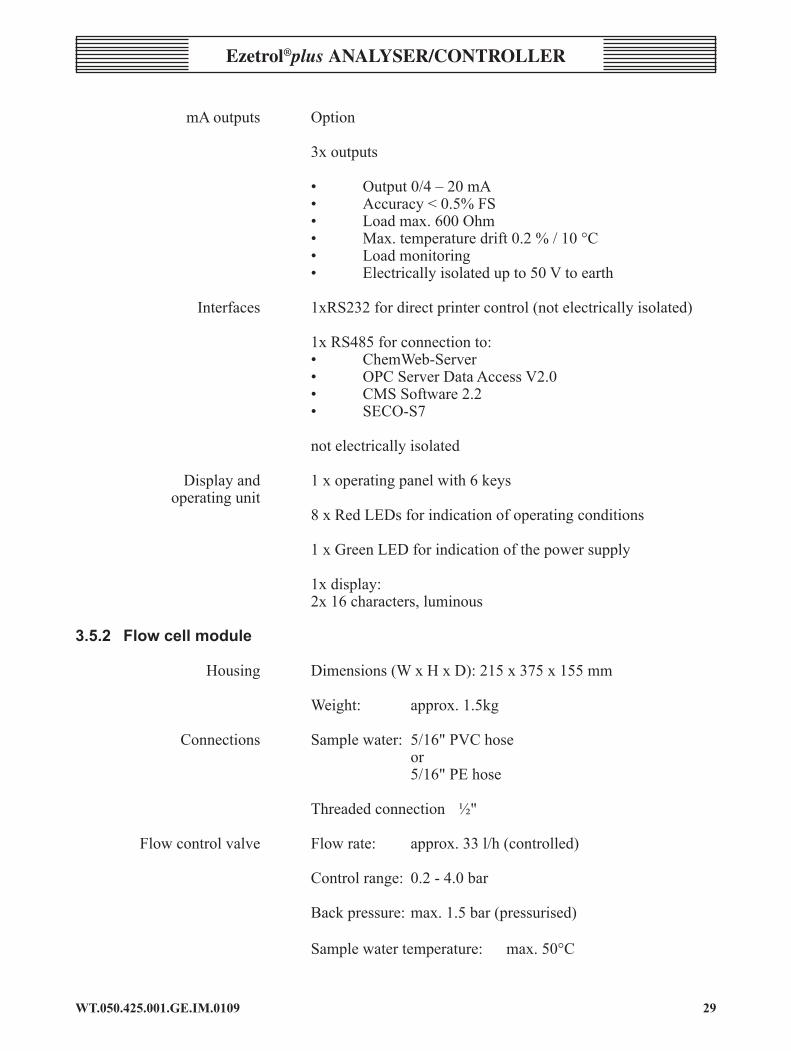
mAoutputs Option
3xoutputs • Output0/4–20mA • Accuracy<0.5%FS • Loadmax.600Ohm • Max.temperaturedrift0.2%/10°C • Loadmonitoring • Electricallyisolatedupto50Vtoearth
Interfaces 1xRS232fordirectprintercontrol(notelectricallyisolated) 1xRS485forconnectionto: • ChemWeb-Server • OPCServerDataAccessV2.0 • CMS Software 2.2 • SECO-S7
not electrically isolated
Displayand 1xoperatingpanelwith6keys operating unit 8xRedLEDsforindicationofoperatingconditions
1xGreenLEDforindicationofthepowersupply 1x display: 2x16characters,luminous
3.5.2 Flowcellmodule
Housing Dimensions(WxHxD):215x375x155mm Weight: approx.1.5kg
Connections Samplewater: 5/16"PVChose or 5/16"PEhose Threadedconnection ½"
Flowcontrolvalve Flowrate: approx.33l/h(controlled) Controlrange: 0.2-4.0bar Backpressure:max.1.5bar(pressurised)
Samplewatertemperature: max.50°C
WT.050.425.00�.GE.IM.0�09�0
Ezetrol®plus analysEr/conTrollEr
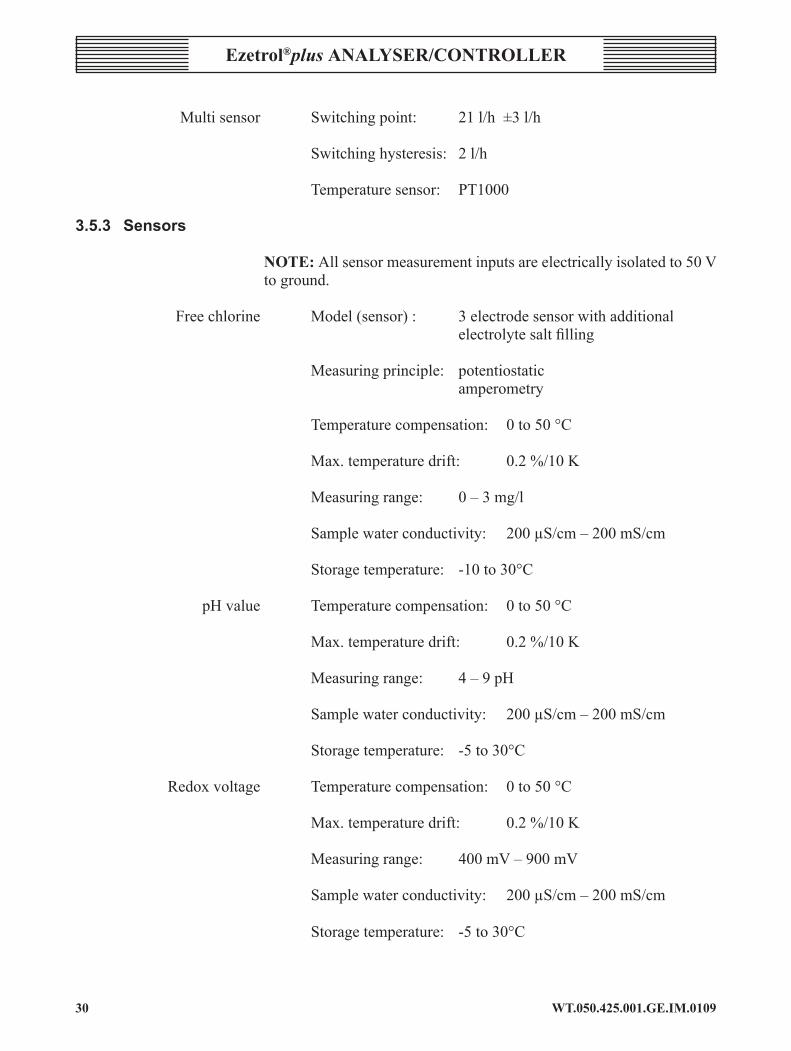
Multisensor Switchingpoint: 21l/h±3l/h
Switchinghysteresis: 2l/h
Temperaturesensor: PT1000 3.5.3 sensors
noTE: Allsensormeasurementinputsareelectricallyisolatedto50Vto ground.
Freechlorine Model(sensor): 3electrodesensorwithadditional electrolytesaltfilling
Measuring principle: potentiostatic amperometry
Temperaturecompensation: 0to50°C Max.temperaturedrift: 0.2%/10K
Measuringrange: 0–3mg/l
Samplewaterconductivity: 200µS/cm–200mS/cm
Storagetemperature: -10to30°C
pHvalue Temperaturecompensation: 0to50°C
Max.temperaturedrift: 0.2%/10K
Measuringrange: 4–9pH
Samplewaterconductivity: 200µS/cm–200mS/cm
Storagetemperature: -5to30°C
Redoxvoltage Temperaturecompensation: 0to50°C
Max.temperaturedrift: 0.2%/10K
Measuringrange: 400mV–900mV
Samplewaterconductivity: 200µS/cm–200mS/cm Storagetemperature: -5to30°C

��WT.050.425.00�.GE.IM.0�09
Ezetrol®plus analysEr/controllEr
4. installation 4.1 Versions
Completesystem
230V Cl2+pH
Completesystem AAC1791consisting ofElectronicmodule AAD8479Flowcellmodule AAE2503
scope of supply Dependingon the individual order, the scopeof supply includes thefollowing:
• Electronicmodule• Flowcellmodule,pressurized• StripsforlabellingtheLEDs• Accessoryset,comprising: fivecableterminalscrews sixblindterminalscrews bushesforclosingemptyductsforthesensorcablesonthe electronicmodule finefilter• Sensorswithaccessories(dependingontheorder): Freechlorine(Cl2) pH value redox • Generallypre-mountedonauPVCbackboard,theunitissupplied withsampleinstallationkit,including: 30mofsamplehose ½"x5/16"strainer ½" x 5/16" push fit sample isolation valve
WT.050.425.00�.GE.IM.0�09�2
Ezetrol®plus analysEr/conTrollEr
• The pre-mounted kit assembly includes: Mounting kit Sensor cleaning solution Operating manual
4.2 transport and storage 4.2.1 transport
Theunitissuppliedinstandardpackaging.Duringtransportthepackagedunitmustbehandledcarefullyandshouldnotbeexposedtowetweatherormoisture. Checkthatthetransportpackagingisundamaged.
Intheeventofdamage,pleaseinformthetransportcompanyimmediately,asyourrightstocompensationwillotherwisebelost.
Iftheunitisdamaged,pleasecontacttherespectiveWallace&Tiernanagencyimmediately.
Keepthepackaginguntiltheunithasbeencorrectlyinstalledandtakeninto operation.
4.2.2 storage
Storetheunitandthesensorsinadryconditionwithoutanyresidualwaterinadryplacethatisnotexposedtotheweather.Storagetemperature,seeSection3.5“TechnicalData”.
4.3 Installation.
Only those persons suitably qualified/trained should undertake the installation of an Ezetrol®plus. Only those persons qualified to carry out electrical installation works should undertake the installation of electrical wiring of an Ezetrol®plus.
4.3.1 transport
During transport the Ezetrol®plus must be handled carefully and should not be exposed to wet weather or moisture.
4.3.2 unpacking
The equipment should be unpacked in a clean, dry area, preferably in the place in which the unit will be installed. All parts should be checked against the enclosed packing note before the packing materials are discarded.

��WT.050.425.00�.GE.IM.0�09
Ezetrol®plus analysEr/controllEr
Upon receipt, immediately check if package is free from damage and that the contents are complete. Report immediately any damage. Handle the sensors carefully when unpacking, as they can be broken if dropped on a hard surface.
notE: Each sensor is shipped with its tip immersed in a small cap of fluid, to prevent it from drying out. Leave the cap in place on the tip until you are ready to install the sensor into a sample cell with a fully established water flow.
4.3.3 location
There are a number of factors that should be considered as you select a location for the controller. These include, but are not limited to:
• A sound mounting surface to adequately support the board assembly.
• A location that is accessible, free from chemical fumes, excessive heat and dampness should be chosen as they can seriously damage the controller. Damage due to chemical fumes, including hydrochloric acid fumes, will invalidate the warranty.
• The controller should be easily accessible for taking display readings or making operating adjustments. Lighting should be adequate and clearance must be provided for service. Do not mount in direct sunlight.
• High voltage transformers and other energy-emitting electrical devices can affect the delicate sensing circuits of the controller. Locate the board assembly as far away as practical from sources of interference and be sure that it is electrically grounded as specified in the wiring diagrams.
• The Ezetrol®plus is designed to be permanently powered. The main power into the unit should NOT be interlocked with main circulation pumps. The controller has a secondary input (external stop), which is used to isolate the dosing pump outputs. This input is volt-free and must not be powered (or the controller will be damaged, invalidating the warranty).
• The main power feed should be provided from a ‘clean’ 10-amp switched and fused source.
• The position of the nearest drain should also be given consideration, as the standard Ezetrol®plus supply requires a drain that is open to atmosphere to which the sample water to runs. An optional return to filtration, post filer, pipework kit is available.
WT.050.425.00�.GE.IM.0�09�4
Ezetrol®plus analysEr/conTrollEr
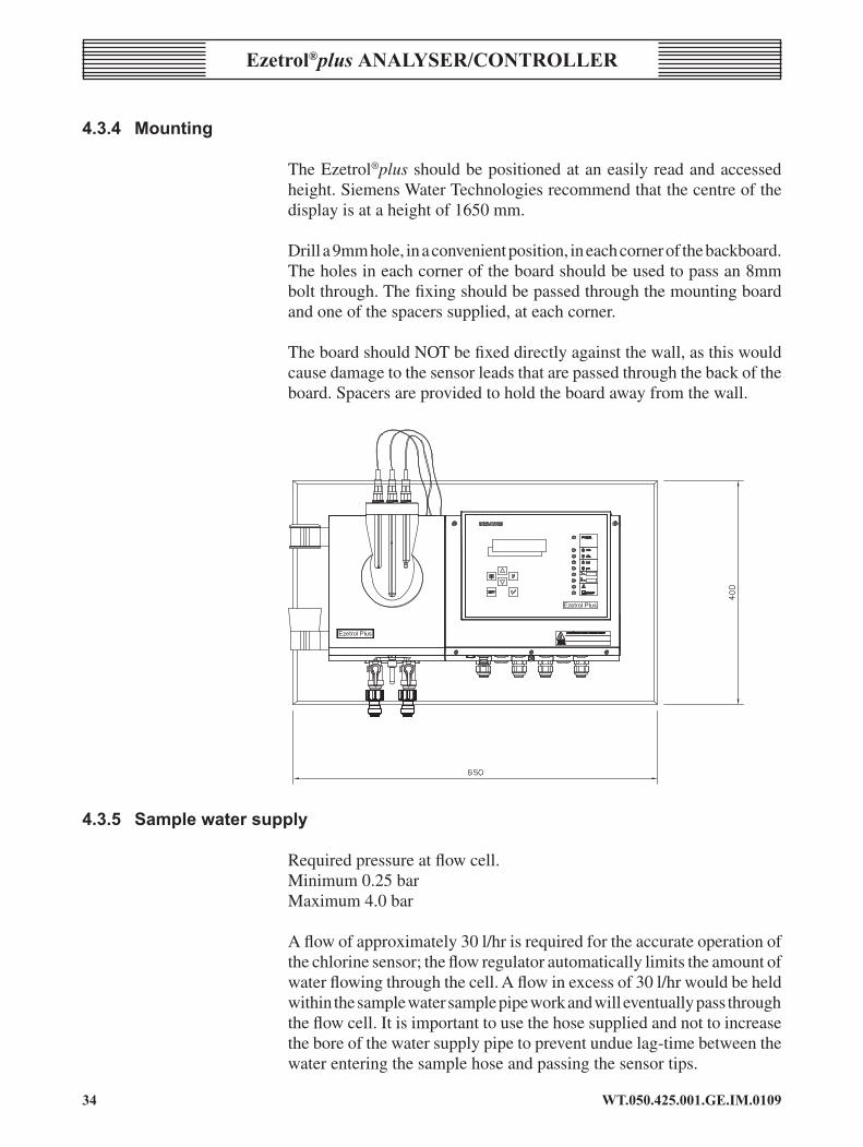
4.3.4 Mounting
The Ezetrol®plus should be positioned at an easily read and accessed height. Siemens Water Technologies recommend that the centre of the display is at a height of 1650 mm.
Drill a 9mm hole, in a convenient position, in each corner of the backboard.The holes in each corner of the board should be used to pass an 8mm bolt through. The fixing should be passed through the mounting board and one of the spacers supplied, at each corner.
The board should NOT be fixed directly against the wall, as this would cause damage to the sensor leads that are passed through the back of the board. Spacers are provided to hold the board away from the wall.
4.3.5 Samplewatersupply
Required pressure at flow cell.Minimum 0.25 barMaximum 4.0 bar
A flow of approximately 30 l/hr is required for the accurate operation of the chlorine sensor; the flow regulator automatically limits the amount of water flowing through the cell. A flow in excess of 30 l/hr would be held within the sample water sample pipe work and will eventually pass through the flow cell. It is important to use the hose supplied and not to increase the bore of the water supply pipe to prevent undue lag-time between the water entering the sample hose and passing the sensor tips.

�5WT.050.425.00�.GE.IM.0�09
Ezetrol®plus analysEr/controllEr
Water from the flow cell is normally fed to the drain. It is also possible to return the ‘waste’ water back to a post filter point in the pool water return, at a maximum back pressure of 1.5 bar. A return water installation kit of parts is available.
If the flow cell sample supply water pressure is less than 0.25 bar, a sample water pump may be installed either from the pool or from the circulation system (preferred). The use of a booster pump must include a loop of pipe work with a sample tapping to draw of a proportion of the water to pass through the sample cell. This prevents the entire pump pressure from being put directly onto the flow regulator and also stops the creation of an artificial lag time.
The sample water supply point must be installed in the delivery pipework between the circulation pump(s) and the filters. However, the sample water point must be installed upstream of the flocculant dosing station an the pressure applied directly to the measuring cell must be at least 0.2 bar. The sample water point must be chosen to ensure that the water sample is representative with a constant, bubble-free flow. The sample supply hose is supplied with the kit of parts. The sample line should be as short as possible. If the sample line is to be longer than 30m refer to Siemens Water Technologies.
A sample strainer must be fitted to ensure that the flow switch, flow regulator and sensors cannot be fouled or damaged by solids passing from the circulation pump supply.
Failure to use the strainer provided will allow debris such as ‘hair & lint’ to pass into the flow regulator and the flow cell. This will compromise the performance of the Ezetrol®plus and will invalidate the warranty.
For sample runs of 20m upwards, a loop from the circulation pump delivery pipework should be taken to a point below or adjacent to the board mount assembly and returned to the suction side of the circulation pump(s).
The sample loop should be run in ½” uPVC pipe, suitably supported throughout its entire length. A ½” tee adjacent to the flow cell should be fitted and a minimal length of 5/16" hose and connected to the adapter on the strainer inlet, out let and then on the to the flow switch mounted directly under the flow cell. The fittings from the tee to the flow cell are included the ½” uPVC pipe and fitting are to be supplied by others.
Please note that if 50% duty circulation pumps are employed, running only one pump only will reduce the sample rate of flow to the flow cell.

WT.050.425.00�.GE.IM.0�09��
Ezetrol®plus analysEr/conTrollEr
Attention should be given to the amount of flow during this period and, if adjusted, the subsequent flow when the second pump flow is restored.
Should the ‘waste’ water be returned to the post filter circulation pipe work remove the ‘tundish’ from the board and the threaded insert, plus the spare threaded insert, used to support an isolation valve.
4.3.6 sensor connection
Remove protective caps from the pH and chlorine sensors. Screw sensors into the flow cell. The chlorine sensor has an integral lead that can not be removed from the sensor. The back nut/thread on the sensor may be screwed into the flow cell without rotating the sensor or ‘knotting’ the lead.
There should be no air bubbles in the tip of the pH sensor, if there are, remove them by gently shaking the sensor (similar to shaking a clinical thermometer).
After start-up, all sensors require a settling-down period of approximately two - four hours. Calibration and other adjustments should only be made after this period and automatic feed control should be switched off. The Ezetrol®plus should not be left in automatic feed mode overnight for 24 hours after first fitting the sensors.
Do not use stabilised chlorine products, as the Ezetrol®plus will not function correctly.
Sensor warranty will be void if the above is not complied with.
4.3.7 Electricalconnections
Only those persons qualified to carry out electrical installation works should undertake the installation of electrical wiring of an Ezetrol®plus.
The electrical supply to the board assembly should be wired via a double pole isolation switch. The supply should be fused at 10 amp max and the location of the fuse clearly identified.
Please refer to wiring diagrams at the rear of this manual for identification of all the terminals to enable cable connection.
The Ezetrol®plus is not provided with internal dosing relay fuses. To ensure the relays and PCB are protected external fuses must be fitted.

��WT.050.425.00�.GE.IM.0�09
Ezetrol®plus analysEr/controllEr
WarnInG: The Ezetrol®plus is designed to be permanently powered. The main power into the unit should NOT be interlocked with main circulation pumps. The controller has a secondary input (external stop), which is used to isolate the dosing pump outputs. This input is volt-free and must not be powered (or the controller will be damaged).
Power requirement: 230V AC, 1PH, 50 Hz.
4.3.8 Samplewaterdrainageline
Thesamplewaterusuallydrainsawaythroughanunpressurisedline.However,apressurisedlinewithmax.1.5baroverpressurecanbeusedasareturnline.Thereisaballvalveinstalledinthesamplewaterreturnlineforthis.Itcanbeusedtoisolatetheflow-throughadapter,e.g.duringcalibration.Thesamplewateradmissionpressuremustalwaysbeatleast0.2barhigherthantheback-pressureonthecelloutlet.Pressurelossesinthereturnlinemustalsobetakenintoconsideration.
HoseConnectors-AAC1632½"Femalex¼"HosePushFitAdaptor
4.4 Commissioning
WarnInG: Electricalhazard.Onlyauthorisedandqualifiedelectriciansarepermittedtoinstallthedeviceandopenthehousing.Theunitmayonly be put into operationwhen the housing is closed, andmust beconnectedtoprotectionearth.Modificationstotheunitthatgobeyondthosedescribedinthismanualarenotpermissible.
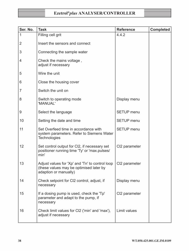
4.4.1 start-up procedure
Theunitcanbetakenintooperationafterithasbeeninstalled.
Thefollowingtablecontainstheindividualcommissioningstepsintheircorrectsequence. More detailed information is contained in the sections listed in the“Reference”column.
Completion of each task can be confirmed in the “Completed”column.
NOTE: If this installation sequencecannotbe compliedwith, pleasecontact the following service address: SiemensWaterTechnologies,PrioryWorks,TonbridgePhone+44(0)1732771777Fax+44(0)1732771800e-mail:[email protected].
WT.050.425.00�.GE.IM.0�09��
Ezetrol®plus analysEr/conTrollEr
ser. no. task reference Completed1
2
3
4
5
6
7
8
9
10
11
12
13
14
15
16
Fillingcellgrit
Insertthesensorsandconnect
Connectingthesamplewater
Checkthemainsvoltage,adjustifnecessary
Wiretheunit
Closethehousingcover
Switchtheuniton
Switchtooperatingmode'MANUAL'
Selectthelanguage
Settingthedateandtime
SetOverfeedtimeinaccordancewithsystemparameters.RefertoSiemensWaterTechnologies
SetcontroloutputforCl2,ifnecessarysetpositionerrunningtime'Ty'or'max.pulses/min'
Adjustvaluesfor'Xp'and'Tn'tocontrolloop(thesevaluesmaybeoptimisedlaterbyadaptionormanually)
ChecksetpointforCl2control,adjust,ifnecessary
Ifadosingpumpisused,checkthe'Tp'parameterandadapttothepump,ifnecessary
ChecklimitvaluesforCl2('min'and'max'),adjustifnecessary
4.4.2
Displaymenu
SETUPmenu
SETUPmenu
SETUPmenu
Cl2parameter
Cl2parameter
Displaymenu
Cl2parameter
Limitvalues
�9WT.050.425.00�.GE.IM.0�09
Ezetrol®plus analysEr/controllEr
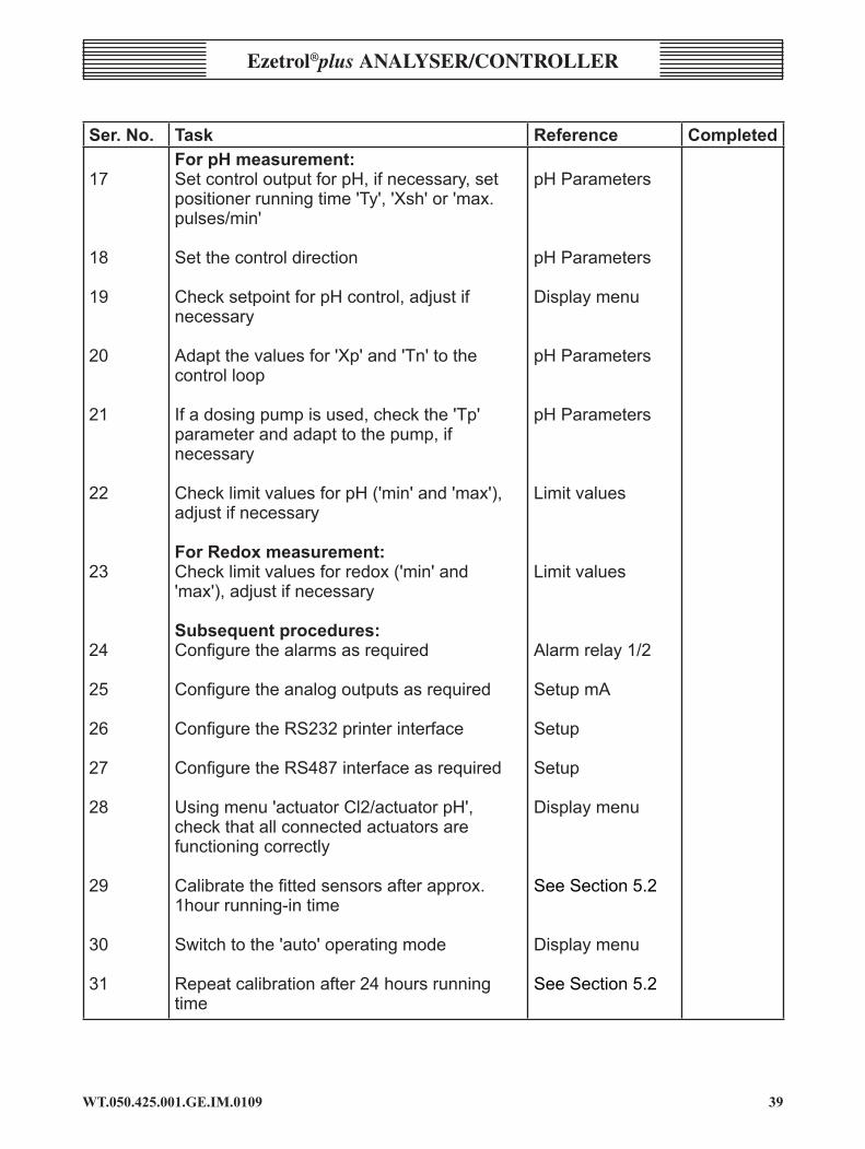
ser. no. task reference Completed
17
18
19
20
21
22
23
24
25
26
27
28
29
30
31
ForpHmeasurement:SetcontroloutputforpH,ifnecessary,setpositionerrunningtime'Ty','Xsh'or'max.pulses/min'
Setthecontroldirection
ChecksetpointforpHcontrol,adjustifnecessary
Adaptthevaluesfor'Xp'and'Tn'tothecontrolloop
Ifadosingpumpisused,checkthe'Tp'parameterandadapttothepump,ifnecessary
ChecklimitvaluesforpH('min'and'max'),adjustifnecessary
ForRedoxmeasurement:Checklimitvaluesforredox('min'and'max'),adjustifnecessary
Subsequentprocedures:Configure the alarms as required
Configure the analog outputs as required
Configure the RS232 printer interface
Configure the RS487 interface as required
Usingmenu'actuatorCl2/actuatorpH',checkthatallconnectedactuatorsarefunctioningcorrectly
Calibrate the fitted sensors after approx. 1hourrunning-intime
Switchtothe'auto'operatingmode
Repeatcalibrationafter24hoursrunningtime
pHParameters
pHParameters
Displaymenu
pHParameters
pHParameters
Limitvalues
Limitvalues
Alarmrelay1/2
SetupmA
Setup
Setup
Displaymenu
SeeSection5.2
Displaymenu
SeeSection5.2
WT.050.425.00�.GE.IM.0�0940
Ezetrol®plus analysEr/conTrollEr
4.4.2 Fillingcellgrit
WarnInG:Ifusingpressurisedversions:Beforeopeningthecover,alwaysshutoffthesupplylineandthedrainagelineandthenreleasethepressureinthecellbodywiththedrainscrew.
1 Unscrewthecoverfromthecellbody
2 Fillhalfascrewcapofwhitecellgritformeasuringcells(U¬93275)intothecellbody.SeeSection6Maintenance.
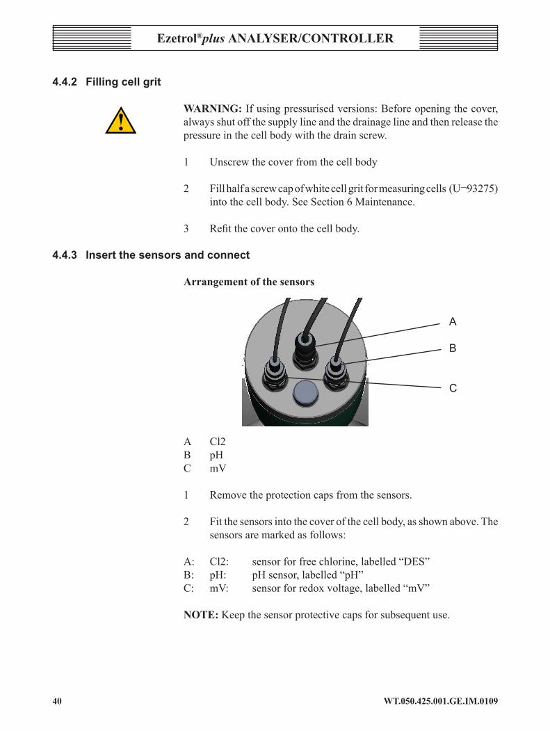
3 Refitthecoverontothecellbody. 4.4.3 Insertthesensorsandconnect
arrangement of the sensors
A
B
C
A Cl2 B pH C mV
1 Removetheprotectioncapsfromthesensors.
2 Fitthesensorsintothecoverofthecellbody,asshownabove.Thesensorsaremarkedasfollows:
A: Cl2: sensorforfreechlorine,labelled“DES”B: pH: pHsensor,labelled“pH”C: mV: sensorforredoxvoltage,labelled“mV”
noTE:Keepthesensorprotectivecapsforsubsequentuse.

4�WT.050.425.00�.GE.IM.0�09
Ezetrol®plus analysEr/controllEr
arrangement of the cables
connecting the sensor cables1 Placethesensorcableswiththeattachedbushesintothecableducts
ofthehousingandconnecttotheelectronicmodule,seeelectricalwiringdiagrams.ThecableofthepHsensorissolderedon.
2 Dependingonthesensordesign,eitherplugorplugandscrewthecableintoplace.
3 Mount the multi-sensor with the temperature measuring cabletotheflowcontrolvalve.Placethetemperaturemeasuringcablethroughaductandconnecttotheelectronicmodule-refertothewiringdiagrams.Notethattheshieldofthefour-coretemperaturemeasuringcablemustalsobeconnected.
4 Insertthesuppliedbushesintoductsthatarenotinuseinordertosealthehousing.
4.4.4 Connectingthesamplewater
caUTIon:Thesamplewatersupplypointmustbelocatedupstreamof the flocculant dosing station.Otherwise, it could influence themeasurements.
sample water inlet connection1 Do not use any copper pipe.

WT.050.425.00�.GE.IM.0�0942
Ezetrol®plus analysEr/conTrollEr
A B C2 Thepressureinthesamplewaterinletmustalwaysbewithina
rangeofmin.0.2tomax.4bar.Atthesametimethepressureinthesamplewaterinletmustgenerallybe0.2barhigherthaninthesamplewateroutlet.
3 Topreventlongprocesstimes,ensurethatthelinesinthesamplewaterinletareasshortaspossible.
4 Anexternalstrainermustbeprovidedforthesamplewaterinlet(PartNo.UXA92304)withameshsizeof0.5mm.
4.5 Connectthedevicetothepowersupply
Refertotheelectricalwiringdiagramsatthebackofthismanual. WarnInG:Onlyauthorisedandqualifiedelectriciansarepermittedtoinstallthedeviceandopenthehousing.Theunitmayonlybeputintooperationwhenthehousingisclosed,andmustbeconnectedtoprotectionearth.Modificationstotheunitthatgobeyondthosedescribedinthismanualarenotpermissible. Thedeviceisnotequippedwithamainsswitchandisinoperationassoonasthesupplyvoltageisapplied.Anexternalswitchorcircuitbreakeristhereforenecessary.Theconductorcross-sectionofthemainscablemustbeatleast0.75mm²;amainsfuseof6Amustbeprovidedbythecustomer.Whenconnectingsystemcomponents(e.g.devices,motors,pumps)andwhenenteringoperatingdata,thesystemcomponentsmustbeswitchedoffin order to prevent uncontrolled activation or any incorrect function.
4�WT.050.425.00�.GE.IM.0�09
Ezetrol®plus analysEr/controllEr
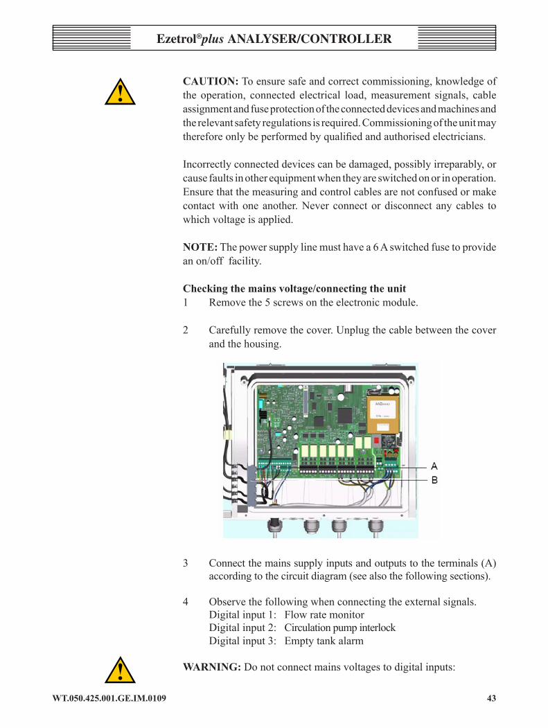
caUTIon:Toensuresafeandcorrectcommissioning,knowledgeofthe operation, connected electrical load,measurement signals, cableassignmentandfuseprotectionoftheconnecteddevicesandmachinesandtherelevantsafetyregulationsisrequired.Commissioningoftheunitmaythereforeonlybeperformedbyqualifiedandauthorisedelectricians.
Incorrectlyconnecteddevicescanbedamaged,possiblyirreparably,orcausefaultsinotherequipmentwhentheyareswitchedonorinoperation.Ensurethatthemeasuringandcontrolcablesarenotconfusedormakecontactwithoneanother.Never connectordisconnect anycables towhichvoltageisapplied. noTE:Thepowersupplylinemusthavea6Aswitchedfusetoprovideanon/offfacility.
checking the mains voltage/connecting the unit1 Removethe5screwsontheelectronicmodule.
2 Carefullyremovethecover.Unplugthecablebetweenthecoverandthehousing.
3 Connectthemainssupplyinputsandoutputstotheterminals(A)accordingtothecircuitdiagram(seealsothefollowingsections).
4 Observethefollowingwhenconnectingtheexternalsignals. Digitalinput1: Flowratemonitor Digitalinput2: Circulationpumpinterlock Digitalinput3: Emptytankalarm
WarnInG:Donotconnectmainsvoltagestodigitalinputs:

WT.050.425.00�.GE.IM.0�0944
Ezetrol®plus analysEr/conTrollEr
caUTIon: To avoid overchlorination or amalfunction of the pHcontroller,thecontrolsystemmustbeconnectedtothecirculationunit.TodothisconnectoneenablecontactofthecirculatingpumptodigitalinputDII(terminals3and4)(seealsoSection3.4.6digitalinputs).
replacing the housing coverIfallcablesareconnected:-
1 Pluginthecablebetweenthecoverandthehousing.
2 Replacethecoveronthehousingandtightenthe5screws,makingsurethatthecablebushingsareseatedcorrectlyandthatnoneofthecablesaretrapped.
4.5.1 Connectingaflocculantpump
Theflocculantpumpiscontrolledviaanunusedalarmrelay.Thealarmrelayisprogrammedsothattheflocculantpumpstopswhenthecirculationunitisstopped.Thisrequiresanenablelinetobeconnectedfromthecirculation control unit to digital input DII.
Menusettingtoactivatetheenableinputofapulsepumpordosingpumpwiththeaidofalarmrelay1(contactonterminals41and42openforcirculationstop):
• Menupath6(alarmrelay1)
• Relayassignment:DII(otherwisenoselectionisdisplayed)
• Relayfunction:N.O.unlatched
• Delay0min.
4.5.2 Switchingtheuniton
requirements• Electricalconnectionsarecomplete.
• Electrodes are inserted and connected.
• Cellgrithasbeenadded.
• Samplewatersupplylineanddrainlineareconnectedhavingbeentestedforleaksandpressure,samplewaterflowing.

45WT.050.425.00�.GE.IM.0�09
Ezetrol®plus analysEr/controllEr
1 Switchonmainsvoltage. theprogrammeversionisbrieflydisplayede.g. EAC1069 V:3.01 22OCT2008 thenthebasicdisplayappears.Theunitisreadyforoperation.
2 Settheparametersforthepositioner,theconnectedpumpandthecontroldirectioninthemenupath'Parameters'.
3 Setthelimitvaluesandfunctionsinthemenupath'Alarms'.
4 Ventthedosingpump,ifnecessary.
5 Caslibratethemeasuringsignalsafterapprox.1hourrunning-intime.Repeatcalibrationafter24hoursofoperation.
6 Checkthemeasuredvaluesbyamanualmeasuremente.g.DPD.
7 Switchovertotheautomaticmodeandcheckthefunctionofthedosingandcontrolsystems.
8 Checktheresponsetofaults
Fault Display responseSamplewater1stop DI flashes
*samplewater?Chlorinemeasurement:Immediately:Dosingpumpcontinuestodoseunchanged,orpositionernolongermoves.
DIstatic*samplewater?
Afterthedelayhaselapsed:Thedosingpumpswitchesofforthepositionercloses
Circulationstop DII*ext.STOP?*(static)orSTANDBY
Thedosingpumpswitchesofforthepositionercloses
Emptydosingtankalarm
DIII*Carboy?(static)
Thedosingpumpswitchesofforthepositionercloses
Airbubbles,thatmayhindertherotationofthecleaning,gritdisappearafteranoperatingtimeofapprox.48hours.
4.6 SystemShutDown
caUTIon: RiskofuncontrolleddosingofchlorineandpH-correctionchemicals.Shutdownthedosingsystem.Iftheinstallationsiteoftheflowcellmodulecouldbeaffectedbyfrost, thesystemmustbeshutdownwellinadvanceofanyfreezingconditions.
WT.050.425.00�.GE.IM.0�094�
Ezetrol®plus analysEr/conTrollEr
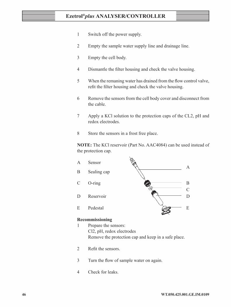
1 Switchoffthepowersupply.
2 Emptythesamplewatersupplylineanddrainageline.
3 Emptythecellbody.
4 Dismantlethefilterhousingandcheckthevalvehousing.
5 Whentheremaningwaterhasdrainedfromtheflowcontrolvalve,refitthefilterhousingandcheckthevalvehousing.
6 Removethesensorsfromthecellbodycoveranddisconnectfromthecable.
7 ApplyaKClsolutiontotheprotectioncapsoftheCL2,pHandredox electrodes.
8 Storethesensorsinafrostfreeplace.
noTE: TheKClreservoir(PartNo.AAC4084)canbeusedinsteadoftheprotectioncap.
A Sensor AB Sealing cap
C O-ring B CD Reservoir D
E Pedestal E
recommissioning1 Preparethesensors: Cl2,pH,redoxelectrodes Removetheprotectioncapandkeepinasafeplace.
2 Refitthesensors.
3 Turntheflowofsamplewateronagain.
4 Checkforleaks.
4�WT.050.425.00�.GE.IM.0�09
Ezetrol®plus analysEr/controllEr
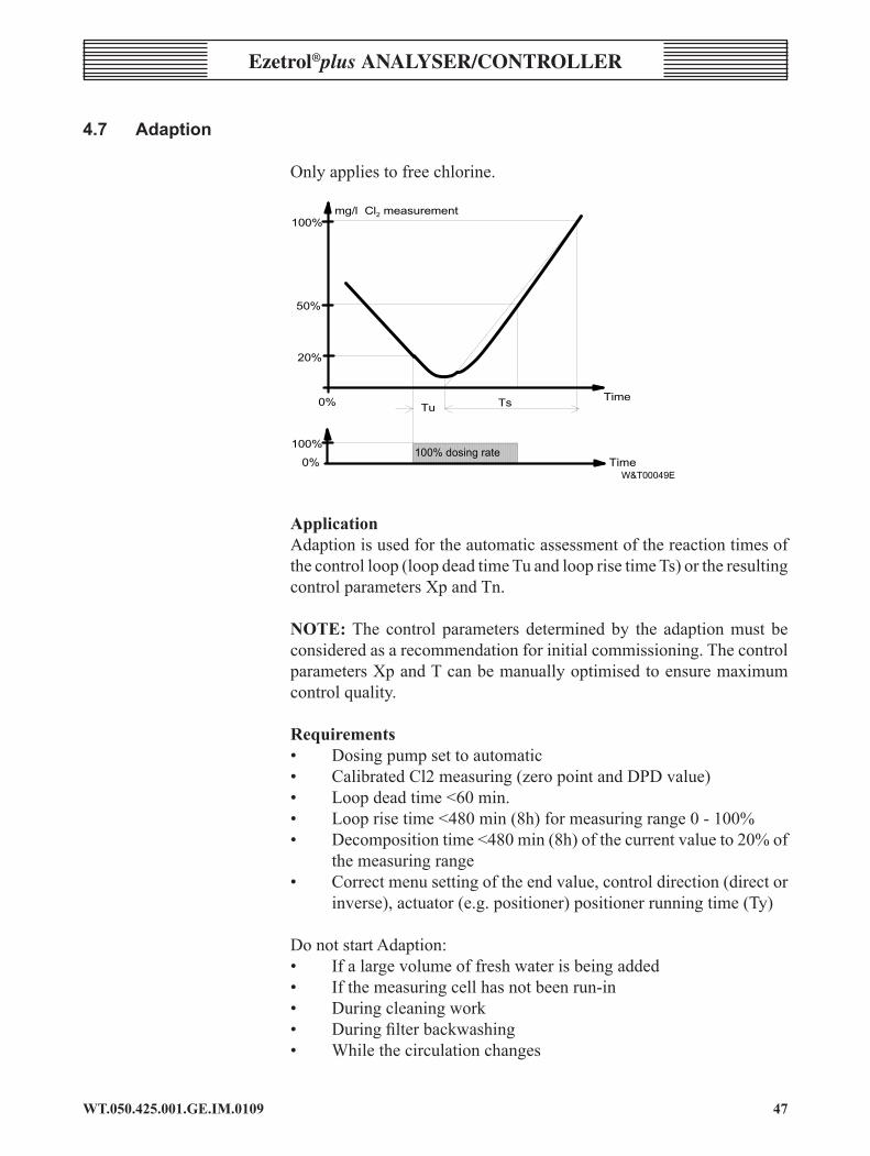
4.7 adaption
Onlyappliestofreechlorine.
� � � �
� � �
� �� �
� � � �
� � � � � � � ��� � � � � � � � � � � �
� � � � � � � � � � � � � � � �
� � � � � � � � �
� � �
� �
� � � �� �
� � � �
applicationAdaptionisusedfortheautomaticassessmentofthereactiontimesofthecontrolloop(loopdeadtimeTuandlooprisetimeTs)ortheresultingcontrolparametersXpandTn.
noTE:The control parameters determinedby the adaptionmust beconsideredasarecommendationforinitialcommissioning.ThecontrolparametersXpandTcanbemanuallyoptimisedtoensuremaximumcontrolquality.
requirements• Dosingpumpsettoautomatic• CalibratedCl2measuring(zeropointandDPDvalue)• Loopdeadtime<60min.• Looprisetime<480min(8h)formeasuringrange0-100%• Decompositiontime<480min(8h)ofthecurrentvalueto20%of
themeasuringrange• Correctmenusettingoftheendvalue,controldirection(director
inverse),actuator(e.g.positioner)positionerrunningtime(Ty)
Do not start Adaption:• Ifalargevolumeoffreshwaterisbeingadded• Ifthemeasuringcellhasnotbeenrun-in• During cleaning work• Duringfilterbackwashing• Whilethecirculationchanges

WT.050.425.00�.GE.IM.0�094�
Ezetrol®plus analysEr/conTrollEr
starting adaption1 Startingatthebasicdisplay,pressFrepeatedlyuntilthe'ADAPTION'
menuisreached.Presstuntilthe'AdaptionCl2'menuisreached.
2 Press 3.'Start>adaption'isdisplayed.
3 Press3 again.
Eachadaptionphaseisthendisplayedwithastatusmessage:
Displaytext Explanation0:Init Initialisation1:Ym=0% Pumpoff2:X=20% Waituntilcurrentvalueis<20%ofthe
controlrange3:X=100% Pumpon4:Ym=100% Waituntilcontrolsignal=100%5:Tu! Initialisingdeadtimemeasurement6:Tu! Measuringtheloopdeadtime7:Tucheck Plausibilityenquirydeadtime8:InitTs Initialisingrisetimemeasurement9:Ts! Measuringtherisetimeuntil50%ofthe
controlrange10:Ts! Calculatingtheloopparametersandthe
controllersettings11:Ym=0% Pumpoff
Theadaptionmenucanbeexitedwhilsttheadaptionisrunning.Adaptionisdisplayedbyaflashingicon ontheleftofthemaindisplay.ThepHcontroller continues running during adaption. I
Theexecutiontimeofthestatusmessagesvaries.Itispossiblethatsomestatusmessagesareonlydisplayedbrieflyornotatalliftheexecutiontimeisveryshort.
noTE:Adaptioncantakeupto13hoursdependingonthecontrolloop.Theremustbeno interruptions in the control loopwhile adaption isrunning(e.g.filterbackwash,changestothecirculationspeedormajorfluctuationsintheuseofthepool).
Adaptioncanbeabortedatanytimebypressing3intheAdaptionmenu.Thepreviouslysetparametersremainunchanged.

49WT.050.425.00�.GE.IM.0�09
Ezetrol®plus analysEr/controllEr
conclusion of adaption without errorsWhenthelooptime(deadtimeTuandrisetimeTs)havebeencompletedwithouterror,calculationofthecontrolparametersXpandTncommences.Thecalculatedparametersareenteredinthemenus.Whenadaptionhasfinished,theEzetrol® plus usesthenewlycalculatedcontrolparametersandcontinuesrunningintheselectedmode(e.g.automatic).
TomonitorthedeterminedlooptimestheyareenteredintotheTuandTsmenus.
If anyerrors in thecontrol loopdooccurduringadaption (e.g.filterbackwashorchangesinthecirculationspeed),thismayleadtoincorrectlooptimes,resultinginwrongcontrolparametersbeingdetermined.
noTE: Performing adaption does not affect the remaining controlparameters.
conclusion of adaption with errorsIf adaption is not successful, the errormessage 'ADAPTION?' isdisplayed.
Iferrorsoccurinthecontrolloopduringadaption(e.g.filterbackwashing,changesinthecirculationorwidelyfluctuatingnumberofvisitorstothepool)orifreactiontimesofthecontrollooparetoolong,adaptionisinterrupted.
Potential faultsInitial value not reached—Whenadaptionhasstartedandthedosingsystemhasclosedorthedosingpumphasswitchedoff,themeasuringamplifierwaitsuntiltheactualvaluehasdroppedbelowtheinitialvalue(0.2xthemeasurementrangevalue)thisdelayisindicatedby2:X=20%beingdisplayedandmustnotexceed8hours.
loop dead time too long—The value determined by the timemeasurementbetweenstartingupdosing,switchingonthedosingpumpsandtheriseoftheactualvaluemayonlytakeamaximumof1hour.Thismeasuredtimeisdisplayedby6:Tu!
loop rise time too long —Thetimeisdeterminedbyameasurementwhichthecontrollooprequiresat100%dosingrateofthedosingsystemorthedosingpump,toincreasetheactualvalueto50%ofthemeasuringrange.Thismeasurementisindicatedby9:Ts!andmaytakeamaximumof4hours.
Ifanyoftheerrorconditionsdescribedaboveoccur,adaptionisinterrupted.Themeasuringamplifierdisplaysafaultmessage.TheoldparametersXpandTnarenotchanged.
WT.050.425.00�.GE.IM.0�0950
Ezetrol®plus analysEr/conTrollEr
DeterminingthecontrolparameterswithknownTuandTsvalues—IfthelooptimeTuandTsarealreadyknownoriftheycannotbedeterminedautomaticallyduetospecificsystemconditions,thelooptimescanbeenteredintotheTuandTsmenus.WhenTuorTsaresaved,thecontrolparametersXpandTnarealsocalculatedandenteredinthemenus.
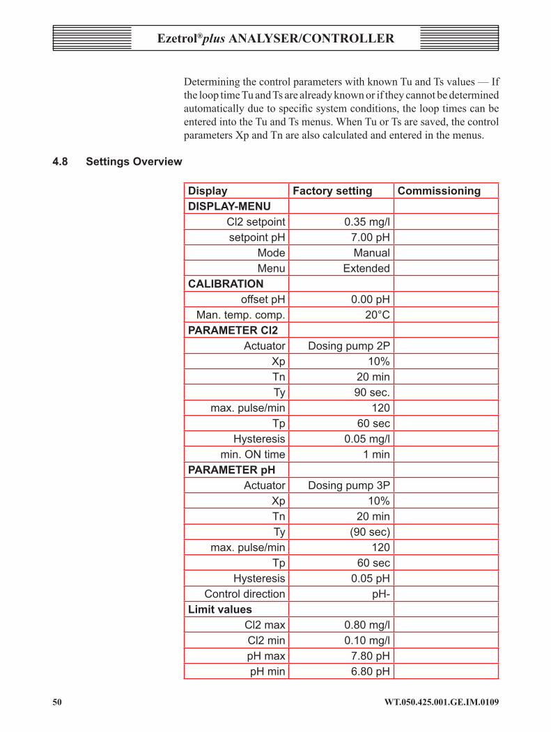
4.8 settings overview
Display factory setting CommissioningDISPLAY-MENU
Cl2setpoint 0.35mg/lsetpointpH 7.00pH
Mode ManualMenu Extended
caliBrationoffsetpH 0.00pH
Man.temp.comp. 20°CPARAMETERCl2
Actuator Dosingpump2PXp 10%Tn 20minTy 90sec.
max.pulse/min 120Tp 60sec
Hysteresis 0.05mg/lmin.ONtime 1min
PARAMETERpHActuator Dosingpump3P
Xp 10%Tn 20minTy (90sec)
max.pulse/min 120Tp 60sec
Hysteresis 0.05pHControldirection pH-
LimitvaluesCl2max 0.80mg/lCl2min 0.10mg/lpHmax 7.80pHpHmin 6.80pH
5�WT.050.425.00�.GE.IM.0�09
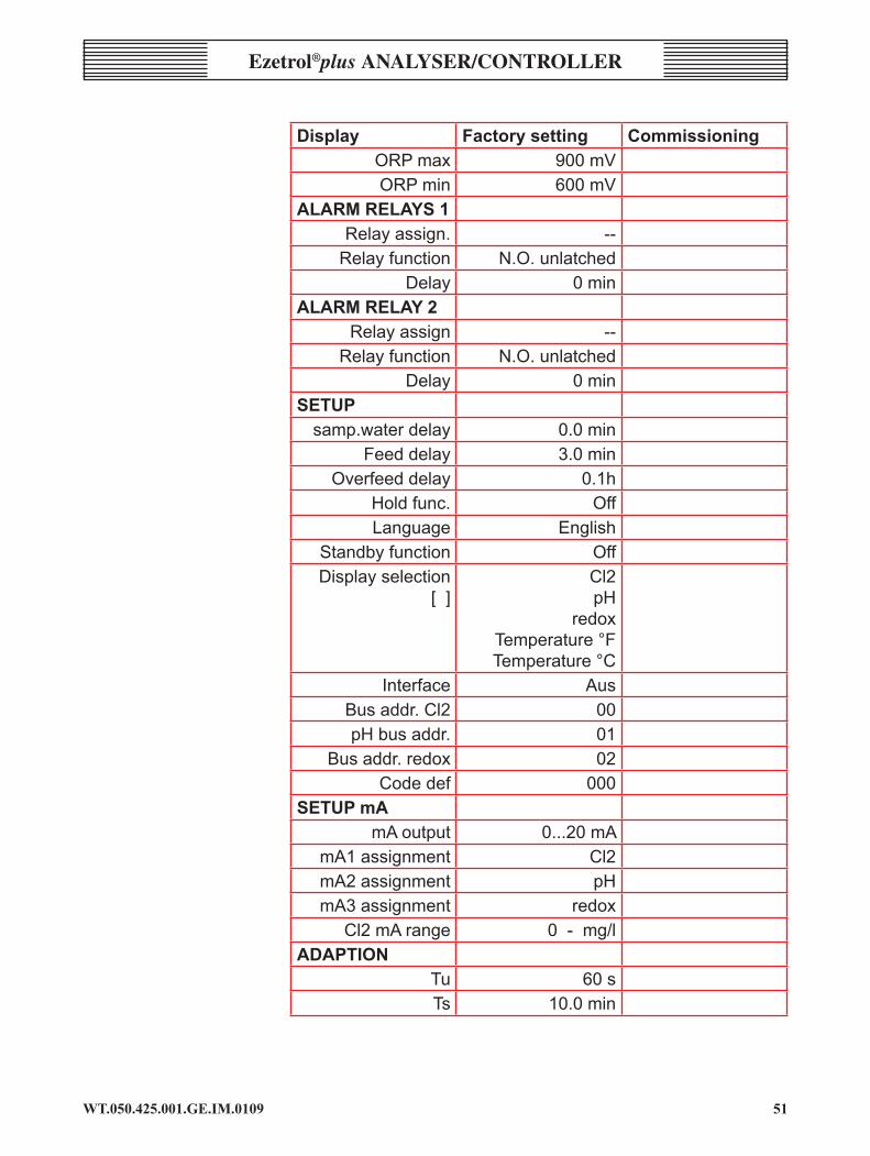
Ezetrol®plus analysEr/controllEr
Display factory setting CommissioningORPmax 900mVORPmin 600mV
ALARMRELAYS1Relayassign. --
Relayfunction N.O.unlatchedDelay 0min
ALARMRELAY2Relayassign --
Relayfunction N.O.unlatchedDelay 0min
setupsamp.waterdelay 0.0min
Feeddelay 3.0minOverfeeddelay 0.1h
Holdfunc. OffLanguage English
Standbyfunction OffDisplayselection
[]Cl2pH
redoxTemperature°FTemperature°C
Interface AusBusaddr.Cl2 00pHbusaddr. 01
Busaddr.redox 02Codedef 000
SETUPmAmAoutput 0...20mA
mA1assignment Cl2mA2assignment pHmA3assignment redox
Cl2mArange 0-mg/ladaption
Tu 60sTs 10.0min

WT.050.425.00�.GE.IM.0�0952
Ezetrol®plus analysEr/conTrollEr
5 operation5.1 DisplayandOperatorControls
Thedisplayunitindicatesimportantdata.TheEzetrol® plus is operated usingsixkeys.Theexactdepictionoftheindividualparametersonthedisplayisdescribedinthefollowingsections.
Exampleofbasicdisplay
A B C D
F EA MeasuredvalueofchlorineB Samplewatertemperatureordigitalinput*)C Adaption runningD ManualorautomaticmodeE Measured redox valueF Measured pH value
Indicators
H ManualmodeA Automaticmode[ ] Option-notselected[3] Option-selected
sTanDByStandbymode,seeSection5.1.3OperatingModes.
*)Whenadigitalinputswitches,thedigitalinputisdisplayedinsteadofthetemperature.
• DI Digitalinput1: flowswitch• DII DigitalinputII: circulationpumpinterlock• DIII DigitalinputIII: emptydosingtankalarm

5�WT.050.425.00�.GE.IM.0�09
Ezetrol®plus analysEr/controllEr
Keys
operating panel
Up• Move up one level• Displaythepreviousoption• Increase value
Down• Move down one level• Displaythenextoption• Decrease value
star• Deletealarmmessage,resetalarmrelay• Acknowledgeerrormessage
Function
• Displaynextmenu
Escape• Cancelinputwithoutsavingnewvalue• Moveuponemenulevel• Displayacknowledgederrormessageagain
Enter• Changetoeditmode• Savechanges
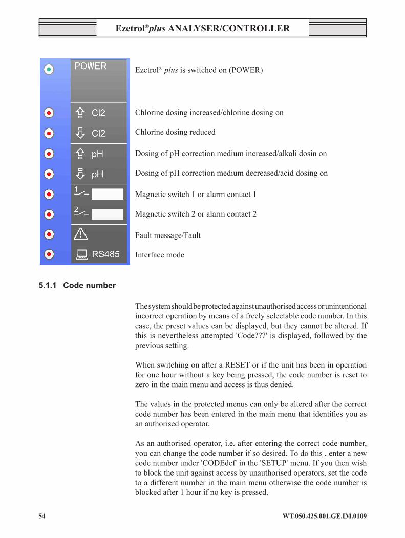
operating indicatorsTheoperatingstateisindicatedby9LEDs.ThemeaningoftheseindicatorsismarkedonthelabellingstriptotherightoftheLEDs.WhentheLEDisilluminated:
WT.050.425.00�.GE.IM.0�0954
Ezetrol®plus analysEr/conTrollEr
Ezetrol® plusisswitchedon(POWER)
Chlorinedosingincreased/chlorinedosingon
Chlorinedosingreduced
DosingofpHcorrectionmediumincreased/alkalidosinon
DosingofpHcorrectionmediumdecreased/aciddosingon
Magneticswitch1oralarmcontact1
Magneticswitch2oralarmcontact2
Faultmessage/Fault
Interfacemode
5.1.1 Codenumber
Thesystemshouldbeprotectedagainstunauthorisedaccessorunintentionalincorrectoperationbymeansofafreelyselectablecodenumber.Inthiscase,thepresetvaluescanbedisplayed,buttheycannotbealtered.Ifthisisneverthelessattempted 'Code???' isdisplayed,followedbytheprevious setting.
WhenswitchingonafteraRESEToriftheunithasbeeninoperationforonehourwithoutakeybeingpressed,thecodenumberisresettozerointhemainmenuandaccessisthusdenied.
Thevaluesintheprotectedmenuscanonlybealteredafterthecorrectcodenumberhasbeenenteredinthemainmenuthatidentifiesyouasanauthorisedoperator.
Asanauthorisedoperator,i.e.afterenteringthecorrectcodenumber,youcanchangethecodenumberifsodesired.Todothis,enteranewcodenumberunder'CODEdef'inthe'SETUP'menu.Ifyouthenwishtoblocktheunitagainstaccessbyunauthorisedoperators,setthecodetoadifferentnumberinthemainmenuotherwisethecodenumberisblockedafter1hourifnokeyispressed.
55WT.050.425.00�.GE.IM.0�09
Ezetrol®plus analysEr/controllEr
Ifyouwishtoallowgeneralaccess,enter'000'inthe'CODEdef'.Thismeansthatallsettingscanbealteredatanytimewithouthavingtoenteracode.InthiscasetheCODEqueryisnotdisplayedinthemainmenu.However,adifferentCODEnumbercanbeenteredunderCODEdefatanytimetodenyaccesstoalloperatorswhodonotknowthenewnumber.
ThedefaultsettingondeliveryisCODEdef=0,whichmeansthatthesettings are not protected.
InformationonhowtoproceedifyouhaveforgottenthecodenumberisgivenunderRESET(menupath11:DIAGNOSIS).
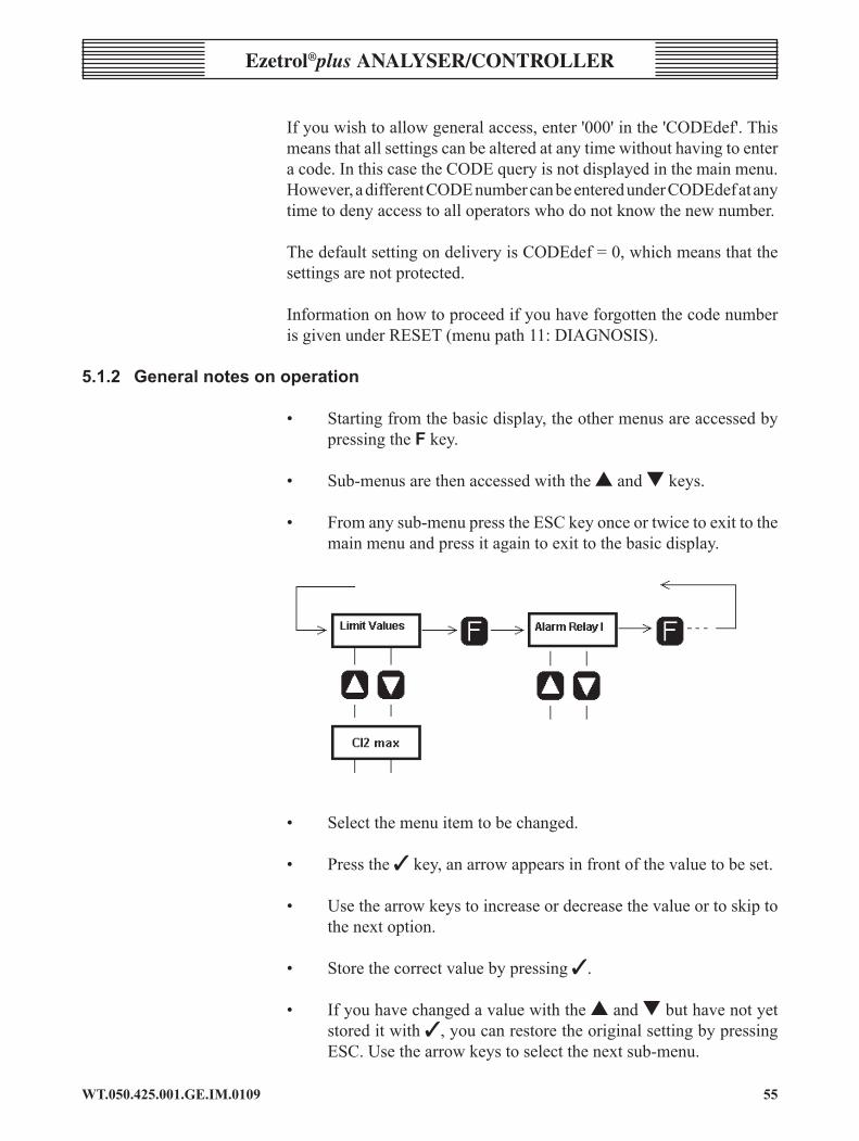
5.1.2 Generalnotesonoperation
• Startingfromthebasicdisplay,theothermenusareaccessedbypressingthef key.
• Sub-menusarethenaccessedwiththes and t keys.
• Fromanysub-menupresstheESCkeyonceortwicetoexittothemainmenuandpressitagaintoexittothebasicdisplay.
• Selectthemenuitemtobechanged.
• Pressthe3key,anarrowappearsinfrontofthevaluetobeset.
• Usethearrowkeystoincreaseordecreasethevalueortoskiptothenextoption.
• Storethecorrectvaluebypressing3.
• Ifyouhavechangedavaluewiththes and tbuthavenotyetstoreditwith3,youcanrestoretheoriginalsettingbypressingESC.Usethearrowkeystoselectthenextsub-menu.
WT.050.425.00�.GE.IM.0�095�
Ezetrol®plus analysEr/conTrollEr
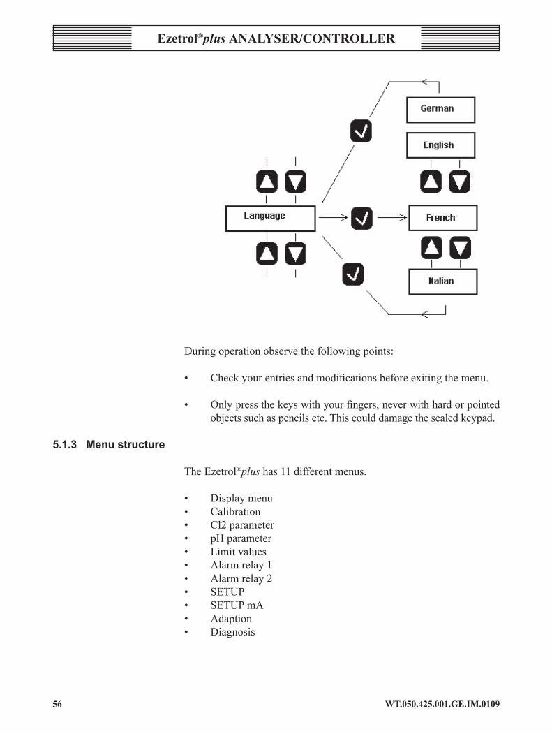
Duringoperationobservethefollowingpoints:
• Checkyourentriesandmodificationsbeforeexitingthemenu.
• Onlypressthekeyswithyourfingers,neverwithhardorpointedobjectssuchaspencilsetc.Thiscoulddamagethesealedkeypad.
5.1.3 Menustructure
TheEzetrol®plushas11differentmenus.
• Displaymenu• Calibration• Cl2parameter• pHparameter• Limitvalues• Alarmrelay1• Alarmrelay2• SETUP• SETUPmA• Adaption• Diagnosis

5�WT.050.425.00�.GE.IM.0�09
Ezetrol®plus analysEr/controllEr
MenuView
Dia
gnos
is
cell
Cl2
pHe
lect
rode
Tem
pera
ture
Rel
ay
Yout
(Cl2
/pH
)
RS
485
Sof
twar
ere
leas
e
*RE
SE
T*
Aut
oTu
ne
Tu Ts
Aut
oTu
ne
Set
upm
A
mA
outp
ut
mA
outp
ut
mA
outp
ut
mA
outp
ut
Set
up
sam
p.w
ater
del
ay
feed
del
ay
over
feed
del
ay
Hol
dfu
nct
Tim
e
Dat
e
Lang
uage
Sta
ndby
func
tion
Dis
play
sel
ect
Inte
rface
code
defi
nitio
n.
Ala
rmR
elay
1/2
rela
yas
sign
.
rela
yfu
nctio
n
alar
md
elay
Ala
rm Cl2
max
Cl2
min
pHm
ax
pHm
in
redo
x.m
ax
redo
x.m
in
tem
p.m
ax
tem
p.m
in
pHp
aram
eter
cont
rolo
utpu
t
prop
ort.
fact
or
Hys
tere
sis
duty
cyc
le
Cl2
par
amet
er
cont
rolo
utpu
t
prop
ort.
fact
or
inte
gr.a
ct.ti
me
duty
cyc
le
zero
Cl2
Cal
ibra
tion
DP
DC
l2
pHc
alib
ratio
n
calib
.tem
p.
man
.com
p.
tem
p.
pHo
ffset
cell
Cl2
pHe
lect
rode
tem
pera
ture
0.00
mg/
l20
°C
7.00
pH
800
mV
actu
ator
Cl2
Set
poin
tCl2
actu
ator
pH
pHs
etpo
int
man
.run
tim
e
Mod
e
Men
u
Cod
e

WT.050.425.00�.GE.IM.0�095�
Ezetrol®plus analysEr/conTrollEr
Menupath1DisplayMenu
DisplayValuerange(defaultsinbold)
description
0.00mg/l20°C7.00pH800mV
Measuredvalues,unitsofmeasurement(basicdisplay)Displayofallmeasuredvalues(chlorine,pH,redox,tempera-ture),manual/automatic,digitalinputsandadaption.
actuatorCl2 OPEN-off-SHUT
oroff-ON
ManualadjustmentofpositionerorCl2dosingpump(notin'AUTO'mode)(isnotdisplayedifchlorinemeasurementisdeactivatedinSETUP).
setpointCl2 0.00mg/l3.00mg/l
(1.50mg/l)
Cl2concentrationsetpointcanonlybesetwithintheselectedmeasuringrange(isnotdisplayedifchlorinemeasurementisdeactivatedinSETUP).
actuatorpH OPEN-off-SHUTor
pH--off-pH+
ManualadjustmentofpositionerorpHdosingpump(notin'AUTO'mode)(isnotdisplayedifpHmeasurementisdeactivatedinSETUP).
pHsetpoint 4.00pH9.00pH
(7.20pH)
pHsetpointcanonlybesetwithintheselectedmeasuringrange(isnotdisplayedifpHmeasurementisdeactivatedinSETUP).
feeddelay 05min Displayscurrentfeeddelay(onlyinAUTOmode)
man.runtime 0.1h PeriodthepumprunsforwhentheOnbuttonispressed.(onlyinMANUALmode)
Mode AutomaticManual
ModeTheselectedmodeisalsoshowninthebasicdisplaybymeansofthe'Auto'or'Manual'symbols.
Menu Conciseextended
MenulengthSelectionofthemenulength-Concisemenu:Displayandcalibrationmenuonly-Extendedmenu:Allmenusaredisplayed.
code 000999
codeEntryofcodenumberThesettingscanonlybechangedifthenumberenteredhereagreeswiththenumberintheCodedef.menu.Otherwise,theerrormessage'code???'appears.Themenudoesnotappearifthenumber'000'hasbeenenteredintheCodedef.menu.Ifthisisthecaseallofthesettingscanbechanged.
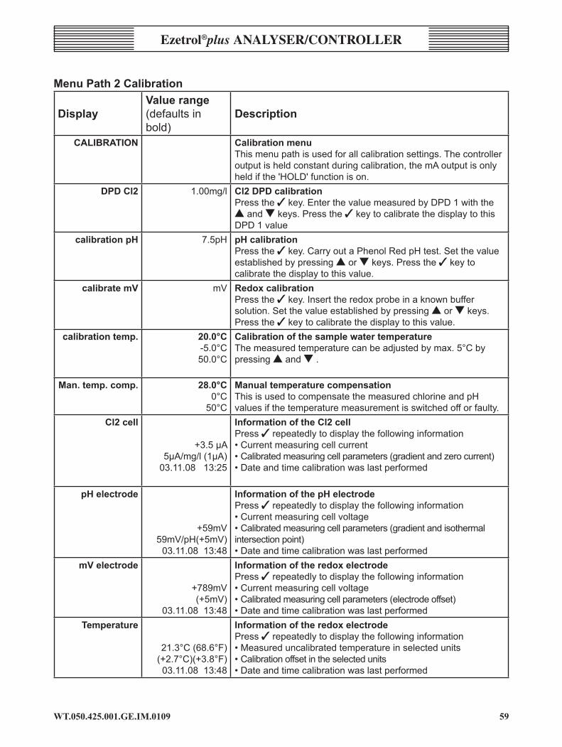
59WT.050.425.00�.GE.IM.0�09
Ezetrol®plus analysEr/controllEr
MenuPath2Calibration
DisplayValuerange(defaultsinbold)
description
caliBration CalibrationmenuThismenupathisusedforallcalibrationsettings.Thecontrolleroutputisheldconstantduringcalibration,themAoutputisonlyheldifthe'HOLD'functionison.
DPDCl2 1.00mg/l Cl2DPDcalibrationPressthe3key.EnterthevaluemeasuredbyDPD1withthesandtkeys.Pressthe3keytocalibratethedisplaytothisDPD1value
calibrationpH 7.5pH pHcalibrationPressthe3key.CarryoutaPhenolRedpHtest.Setthevalueestablishedbypressingsortkeys.Pressthe3keytocalibratethedisplaytothisvalue.
calibratemV mV RedoxcalibrationPressthe3key.Inserttheredoxprobeinaknownbuffersolution.Setthevalueestablishedbypressingsortkeys.Pressthe3keytocalibratethedisplaytothisvalue.
calibrationtemp. 20.0°C-5.0°C50.0°C
CalibrationofthesamplewatertemperatureThemeasuredtemperaturecanbeadjustedbymax.5°Cbypressingsandt.
Man.temp.comp. 28.0°C0°C
50°C
ManualtemperaturecompensationThisisusedtocompensatethemeasuredchlorineandpHvaluesifthetemperaturemeasurementisswitchedofforfaulty.
Cl2cell
+3.5µA5µA/mg/l(1µA)
03.11.0813:25
InformationoftheCl2cellPress3repeatedlytodisplaythefollowinginformation•Currentmeasuringcellcurrent•Calibratedmeasuringcellparameters(gradientandzerocurrent)•Dateandtimecalibrationwaslastperformed
pHelectrode
+59mV59mV/pH(+5mV)
03.11.0813:48
InformationofthepHelectrodePress3repeatedlytodisplaythefollowinginformation•Currentmeasuringcellvoltage•Calibratedmeasuringcellparameters(gradientandisothermalintersectionpoint)•Dateandtimecalibrationwaslastperformed
mVelectrode
+789mV(+5mV)
03.11.0813:48
InformationoftheredoxelectrodePress3repeatedlytodisplaythefollowinginformation•Currentmeasuringcellvoltage•Calibratedmeasuringcellparameters(electrodeoffset)•Dateandtimecalibrationwaslastperformed
Temperature
21.3°C(68.6°F)(+2.7°C)(+3.8°F)03.11.0813:48
InformationoftheredoxelectrodePress3repeatedlytodisplaythefollowinginformation•Measureduncalibratedtemperatureinselectedunits•Calibrationoffsetintheselectedunits•Dateandtimecalibrationwaslastperformed

WT.050.425.00�.GE.IM.0�09�0
Ezetrol®plus analysEr/conTrollEr
MenuPath3Cl2PARAMETER
DisplayValuerange(defaultsinbold)
description
PARAMETERCl2 Cl2controllermenuThismenuisusedforallchlorinecontrollersettings
controloutputPositionermot.
Dosingpump2PSolenoidpump2P
Dosingcontact
ControloutputforCl2dosingPositioner:forgasfeeders,adjustmentofpumpstroke.Dosingpump:PulselengthcontrolofdosingpumpPulsepump:PulsefrequencycontrolofsolenoiddosingpumpDosingcontact:forOSECA
proport. factor 1%1000%(10%)
ProportionalfactorXp
integr.act.time 0.0min(0.1min)100.0min(20.0min)
IntegraltimeTnEntering0.0mincausestheIparttoswitchoffsothatthecontrollerthenoperatespurelyasaPcontroller.Thelowerpositionerlimitmustneverbelowerthan0.1min.
dutycycle 10-180sec.(60sec)
Adjustmentoftheoperatingcycle(Tp)Thisadjustmentisonlypossiblewithnormalmotorpumps
Max.pulses/min
100120
MaximumpulsesperminuteAccordingtothedesignofthepHcorrectionsolenoidpump.NOTE:Onlyifpulse.pumpisselected.
Hysteresis 0.01mg/l0.50mg/l0.05mg/l
HysteresissettingThissettingisusedtospecifythedeadtimebetweenswitchingthedosingcontactonandoff(onlyapplicabeifusingthedosingcontact).
min.ONtime 1min120min
SettingoftheminimumdutycycleThissettingdeterminestheminimudutycycleofthedosingcontact(onlyifusingadosingcontact).
ty 10sec180sec(90sec)
RunningtimeofthepositionerTherunningtimeofthepositionermustbeenteredhereasavaluebetween0%and100%(onlyifusingapositioner).
Max.pulse/min. 100120
MaximumnumberofpulsesperminuteInaccordancewiththeratingofthedosingpump(onlywhensettingthepulsefrequency).
zeroCl2 0.00mg/l Cl2zerocalibrationPress3tozerothedisplay(max.±5µApermitted)
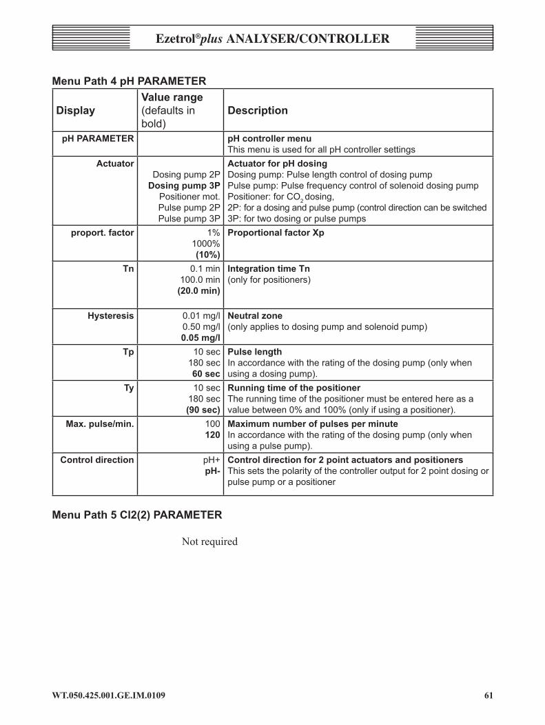
��WT.050.425.00�.GE.IM.0�09
Ezetrol®plus analysEr/controllEr
MenuPath4pHPARAMETER
DisplayValuerange(defaultsinbold)
description
pHPARAMETER pHcontrollermenuThismenuisusedforallpHcontrollersettings
actuatorDosingpump2PDosingpump3P
Positionermot.Pulsepump2PPulsepump3P
ActuatorforpHdosingDosingpump:PulselengthcontrolofdosingpumpPulsepump:PulsefrequencycontrolofsolenoiddosingpumpPositioner:forCO2dosing,2P:foradosingandpulsepump(controldirectioncanbeswitched3P:fortwodosingorpulsepumps
proport. factor 1%1000%(10%)
ProportionalfactorXp
tn 0.1min100.0min(20.0min)
IntegrationtimeTn(onlyforpositioners)
Hysteresis 0.01mg/l0.50mg/l0.05mg/l
Neutralzone(onlyappliestodosingpumpandsolenoidpump)
tp 10sec180sec60 sec
PulselengthInaccordancewiththeratingofthedosingpump(onlywhenusingadosingpump).
ty 10sec180sec(90sec)
RunningtimeofthepositionerTherunningtimeofthepositionermustbeenteredhereasavaluebetween0%and100%(onlyifusingapositioner).
Max.pulse/min. 100120
MaximumnumberofpulsesperminuteInaccordancewiththeratingofthedosingpump(onlywhenusingapulsepump).
Controldirection pH+pH-
Controldirectionfor2pointactuatorsandpositionersThissetsthepolarityofthecontrolleroutputfor2pointdosingorpulsepumporapositioner
MenuPath5Cl2(2)PARAMETER
Notrequired

WT.050.425.00�.GE.IM.0�09�2
Ezetrol®plus analysEr/conTrollEr
MenuPath6LIMITVALUES
DisplayValuerange(defaultsinbold)
description
LIMITVALUES AlarmsmenuSettingofthelimitvaluesofallmeasurements
Cl2max Measuringrange0.80mg/l
MaxCl2limitvalue
Cl2min Measuringrange0.10mg/l
MinCl2limitvalue
pHmax Measuringrange7.8pH
MaxlimitvalueofpH
pHmin Measuringrange6.8pH
MaxlimitvalueofpH
Redoxmax. Measuringrange900mV
Maxlimitvalueofredox
Redoxmin. Measuringrange600mV
Maxlimitvalueofredox
Temp.max. Measuringrange35°C
Maxlimitvalueoftemperature
Tempmin. Measuringrange20°C
Maxlimitvalueoftemperature
noTE: Thismenuisonlyusedtodefinetheswitchingthresholdvalues.WhetherornotthefaultsignallingrelayisactivatedisspecifiedintheMenuPaths7and8under'Alarmrelay1and11'.
MenuPath7ALARMRELAY1
DisplayValuerange(defaultsinbold)
description
ALARMRELAY1 Alarmrelay1menuThismenupathisusedtospecifylimitvaluesandexternalsignalsthatactivatetheswitchingofrelay1.Italsosetsthemodeofoperationoftherelayandtheswitchingdelaytimeoftherelay

��WT.050.425.00�.GE.IM.0�09
Ezetrol®plus analysEr/controllEr
DisplayValuerange(defaultsinbold)
description
Relayassign. Cl2maxCl2minpHmaxpHmin
redoxmaxredoxmin
DI1DI2DI3
Alarm1relayassignmentThismenupathisusedtospecifylimitvaluesandexternalsignalsthatactivatetheswitchingofrelay1.Italsosetsthemodeofoperationoftherelayandtheswitchingdelaytimeoftherelay
Relayfunction N.O.unlatchedN.C.unlatched
N.O.latchedresN.C.latchedresN.O.latchedackN.C.latchedack
Functionofalarmrelay1
Delay 0min600min0min
DelayuntiltherelayswitchesTheindicatorilluminatesimmediatelyafterthealarmhasbeensent;howevertherelayswitchesattheendofthedelaytime
MenuPath8ALARMRELAY2
AsALARMRELAY1exceptfor
relay function PAC TurnoffonHighandLowpH,noflowandexternalstop.

WT.050.425.00�.GE.IM.0�09�4
Ezetrol®plus analysEr/conTrollEr
MenuPath9SETUPDisplay Valuerange
(defaultsinbold)description
setup SETUPmenu(generalsettings,interface)samplewater
delay0.0min
10.0min0.0min
Delaytimeforsamplewatermonitoring(DI1)Afterfailureofthesamplewater,thecontroloutputsremainunchangedforthislenghtoftime.Thenthedosingpumpstopsandthepositionercloses.(settingto0.0hdeactivatesthisfunction).
feed.delay 0.0min99.0min3.0min
FeeddelayController-switchondelayforH/Aswitching,samplewaterfailure,circulationshut-offortankempty-message.(settingto0.0hdeactivatesthisfunction)
overfeeddelay 0.1h24hn0.5h
MaximumdosingtimeIf a controller maintains a flow rate of 100% longer than this time, thecontrollersaredeactivated.(0.0hdeactivatesthisfunction).
Holdfunction offOn
HoldfunctionWhenactivated,thevalue(mAoutput,limitvalue,etc.)remainsunchangedduringcalibration.
time 11:18 Settingtheinternalreal-timeclockdate 03.11.08 Settingtheinternalreal-timeclock
language German,EnglishFrench,ItalianDutch,Czech
Polish,Hungarian
Menulanguage
standby function onOff
standby functionThemainmenudisappears('Standby'display)anderrormessagesaresuppressedwhensetto'Circulationoff'(DII).Acknowledgebypressinganykeyinthemainmenu.
Displayselect Cl2pH
redoxTemperature°FTemperature°C
SelectionofthedisplayedmeasuredvaluesOptionsdifferdependingontheversionoftheunit.
interface offPrinter
RS485(1)
Selectionoftheoperatingmodeoftheinterface
Busaddr.Cl2 0..3100
BusAddressforbusmodefortheCl2values
pHbusaddr. 0...3101
BusAddressforbusmodeforthepHvalues
Bus addr. redox 0...3102
BusAddressforbusmodefortheredoxvalues
Codedefinition 000999
SpecificationoftheusercodenumberIfsetto'000',allsettingscanbechanged.Withanyothersetting,theusercanonlymakechangesifthiscodehasalsobeenteredinthe'Code'menuinthedisplaymenu.Aftertheunithasbeenrunningforonehourwithoutakeybeingpressed,thevalueinthe'Code'menurevertsto'000'andaccessisdeniedonceagain.AfullsystemRESETalsoresetsthevalueinthe'Codedef.'menuto'000'.
noTE:Inabussystem,noaddresscanbeassignedtwice.

�5WT.050.425.00�.GE.IM.0�09
Ezetrol®plus analysEr/controllEr
MenuPath10SETUPmA
DisplayValuerange(defaultsinbold)
description
setup SETUPmenu(generalsettings,interface)mAoutput 0...20mA
4...20mAoff
mAsignaloutput
mA1assignment Cl2pH
Temperature
AssignmentofmAoutput1
mA2assignment Cl2pH
Temperature
AssignmentofmAoutput2
mA3assignment Cl2pH
Temperature
AssignmentofmAoutput3
Cl2mArange 0-10mg/l0-1mg/l0-2mg/l0-3mg/l0-5mg/l
MeasuringrangeofmAoutputforCl2AdjustmentofthemAoutputtothecontinuouslinerecorder
MenuPath11AUTOTUNEfortheCl2controller
DisplayValuerange(defaultsinbold)
description
auto tune AutomatictuningInthismenupathyoucancalculatetheparametersXpandTnfromthevaluesenteredmanuallyforthecontrolcircuitsloopdeadtimeTuandtherisetimeTs,oryoucanstartaprogrammetodeterminethesevaluesautomatically(see'Autotune'menubelow).TheparametersforpHcontrolremainunchanged.
tu 60 sec3600sec
(equals60min)
LoopdeadtimeTuAftereachalterationofTu(storedwithE),theparametersXpandTnarerecalculated.ThecurrentvalueofthelooprisetimeTsisusedforthis.Afterautotuningiscomplete,thevaluedeterminedforthelooprisetimeTuisdisplayed
ts 10.0min480.0min
(equals8h)
LooprisetimeTsEverytimeTsischanged(storedwithE),theparametersXpandTnarerecalculatedonthebasisofthecurrentvalueoftheloopdeadtimeTu.AfterautotuningiscompletethevaluedeterminedforthelooprisetimeTsisdisplayed.
auto tune Start StartingautomatictuningMenuforstartingautomatictuning.Onceithasstarted,autotuningrunstocompletionoritiscancelled.Onceautotunehasfinished the parameters Xp and Tn are recalculated. After auto tune, the measuring amplifier continues to run in the mode that waspreviouslyselected(e.g.automatic).Whileautotuningisrunning,thestatusmessagesaredisplayedinthismenu.Toabortautotuning,press3.
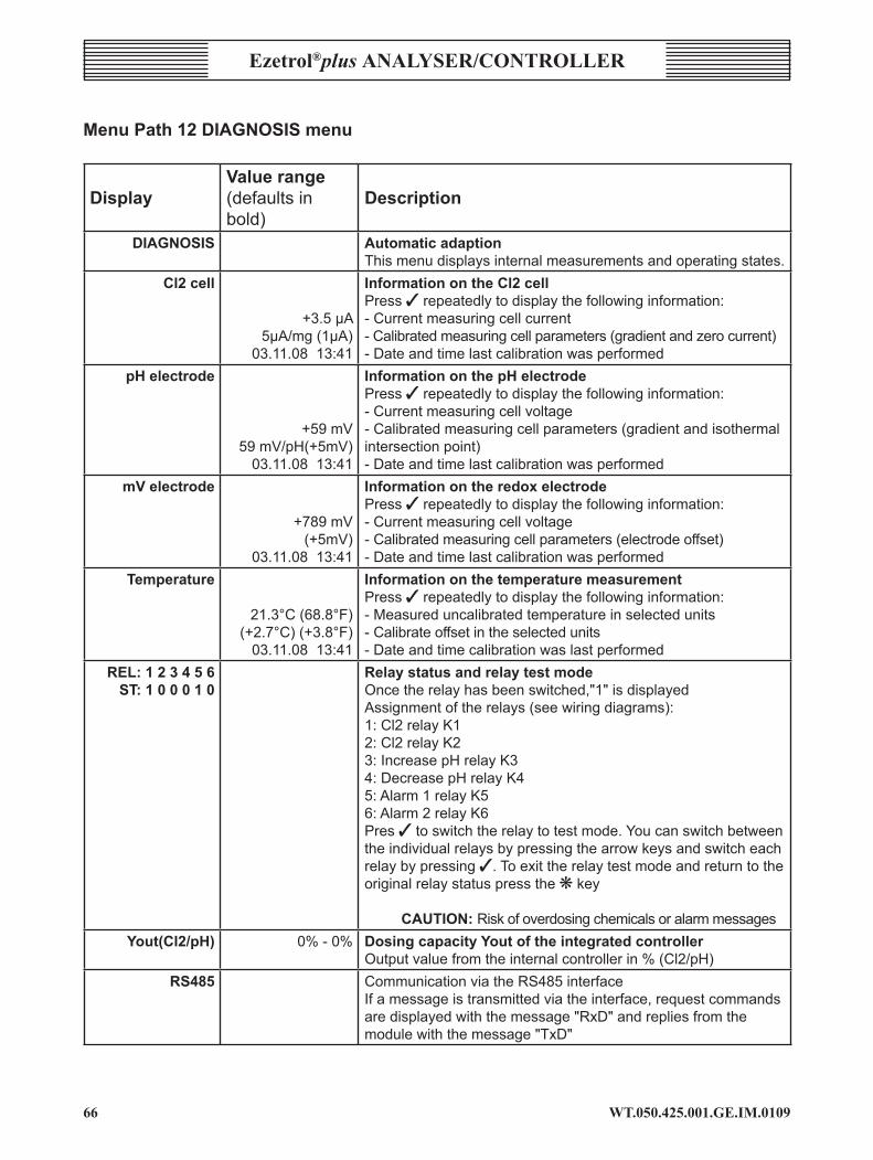
WT.050.425.00�.GE.IM.0�09��
Ezetrol®plus analysEr/conTrollEr
MenuPath12DIAGNOSISmenu
DisplayValuerange(defaultsinbold)
description
diagnosis AutomaticadaptionThismenudisplaysinternalmeasurementsandoperatingstates.
Cl2cell
+3.5µA5µA/mg(1µA)
03.11.0813:41
InformationontheCl2cellPress3repeatedlytodisplaythefollowinginformation:-Currentmeasuringcellcurrent-Calibratedmeasuringcellparameters(gradientandzerocurrent)-Dateandtimelastcalibrationwasperformed
pHelectrode
+59mV59mV/pH(+5mV)
03.11.0813:41
InformationonthepHelectrodePress3repeatedlytodisplaythefollowinginformation:-Currentmeasuringcellvoltage-Calibratedmeasuringcellparameters(gradientandisothermalintersectionpoint)-Dateandtimelastcalibrationwasperformed
mVelectrode
+789mV(+5mV)
03.11.0813:41
InformationontheredoxelectrodePress3repeatedlytodisplaythefollowinginformation:-Currentmeasuringcellvoltage-Calibratedmeasuringcellparameters(electrodeoffset)-Dateandtimelastcalibrationwasperformed
Temperature
21.3°C(68.8°F)(+2.7°C)(+3.8°F)
03.11.0813:41
InformationonthetemperaturemeasurementPress3repeatedlytodisplaythefollowinginformation:-Measureduncalibratedtemperatureinselectedunits-Calibrateoffsetintheselectedunits-Dateandtimecalibrationwaslastperformed
REL:123456ST:100010
RelaystatusandrelaytestmodeOncetherelayhasbeenswitched,"1"isdisplayedAssignmentoftherelays(seewiringdiagrams):1:Cl2relayK12:Cl2relayK23:IncreasepHrelayK34:DecreasepHrelayK45:Alarm1relayK56:Alarm2relayK6Pres3toswitchtherelaytotestmode.Youcanswitchbetweentheindividualrelaysbypressingthearrowkeysandswitcheachrelaybypressing3.Toexittherelaytestmodeandreturntotheoriginalrelaystatuspressthekkey
CAUTION:RiskofoverdosingchemicalsoralarmmessagesYout(Cl2/pH) 0%-0% DosingcapacityYoutoftheintegratedcontroller
Outputvaluefromtheinternalcontrollerin%(Cl2/pH)rs485 CommunicationviatheRS485interface
Ifamessageistransmittedviatheinterface,requestcommandsaredisplayedwiththemessage"RxD"andrepliesfromthemodulewiththemessage"TxD"

��WT.050.425.00�.GE.IM.0�09
Ezetrol®plus analysEr/controllEr
DisplayValuerange(defaultsinbold)
description
Softwarerelease V:3.0123OCT.2008
EAE1069FRG49
Displayofthesoftwaredataoftheunit(importantincaseofqueries)
*reset* Restartoftheunit(RESET)Press3torestarttheunit
5.1.4 Operatingmodes
AutomaticSymbol AutomaticcontrolofthedosingunitsforchlorineandpHaccordingtothemeasuredvaluesandspecifiedsetpointvalues.
Manual Symbol Dosing is not automatically controlled in theMANUALmode.The valuesmust be continuouslymonitored.TheMANUALmodeisused:
• Intheeventofanypossiblesystemfaults• Duringmaintenance/cleaningworkorwhilecheckingthesystem
TheMANUALmodeleadto:
• Pumpsoff• caUTIon:RiskofoverchlorinationoroverdosingofpHcorrection
media.• Ifnecessaryadjustitspositionusingthemenu"actuatorCl2"or
"actuatorpH".
STOPDisplay:Dl,Dll,DlllSTOPmodeisautomaticallyactivated:
• Intheeventofadisturbanceinthesamplewaterflowrate(Dl)• Whenastopsignalissentfromfromoneoftheotherdigitalinputs
DII or DllI• When theDII contact drops out the displaywill not show the
measured values or any error messages, simply displayingSTANDBYonthescreen.
The following messages are also displayed:
• Dl * sample water?• Dll * ext. release?• Dlll * carboy?

WT.050.425.00�.GE.IM.0�09��
Ezetrol®plus analysEr/conTrollEr
STOP results in:
• Pumps off If the conditions that cause the unit to stop no longer apply, the
system automatically switches over to automatic (possibly delayed by a dosing delay).
flashes Sample water or dosing delay currently running
auto tune Automatictuningmodeisactivatedfromthe"autotune"menu(seeSection4.7).Theautotunestepsaredisplayedduringactivation.
stanDBy When the standby function is activated, the measured values and error messages are not displayed if there is an open contact on DlI (circulation stop).
This function is primarily used in private pools where the circulation system does not operate the whole day. During stoppages, these values and the associated error messages are not displayed because this might confuse the operator.
Preset alarms are also active in the standby mode. The stop function (controller stop) continues to operate
5.1.5 SwitchingtheEzetrolplus on and off
Theoperatorwillonlybeabletoswitchthesystemonifthemeasuringancontrolsystemhasbeenproperlyinstalledandcommissionedbyspecialists.Theunitusuallyoperatesintheautomaticmode.Thedosingofchemicalsis controlled according to:
• Thesetpointandmeasuredvalues and• thesignalsonthedigitalinputs(samplewaterSTOP,controller
STOPanddosingtankempty).
Ingeneral,alltheoperatorhastodois:
• Exchangethecontainersholdingchemicals.• Checkandcalibratethemeasuredvalues.• Ifnecessary,remedysimplefaults.
Turnonautomaticoperation—startingfromthebasicdisplay:
1 Pressthetkeyuntilthe"Mode"menuappears.

�9WT.050.425.00�.GE.IM.0�09
Ezetrol®plus analysEr/controllEr
2 Press 3.
3 Selectoperatingmode"AUTO"usingthet key.
4 Press3.Theautomaticmodeisswitchedon.Thedosingsystemswitcheson(providedthatthereisanexternalenable).
5 PressESCtoreturntothebasicdisplay.
5.1.5 Toswitchtheentiresystemoff
Temporaryshutdown 1 Switchofftheexternalmainswitch.
2 Ifnecessary,shutoffthesamplewatersupplylineandreturnline.
for extended periods
WarnInG: RiskofuncontrolleddosingofchlorineorpH-correctionmedium.Shutdowndosingsystem,closepositioner.
WarnInG: Iftheinstallationsiteoftheflowblockassemblyisnotfrostfree,thesystemmustbeshutdowninduetime.
1 Switchoffthepowersupply.
2 Drainthesamplewatersupplylineanddrainline.3 Emptythecellbody.
4 Dismantlethefilterhousingandthecheckvalvehousing.
5 Whentheremainingwaterhasdrainedfromtheflowcontrolvalve,refitthefilterhousingandthecheckvalvehousing.
6 Removethesensorsfromthecellbodycoveranddisconnectfromthecable.
7 PutsomeKClsolutionintheprotectioncapsoftheCl2,pHandredoxelectrodesandfitontotheelectrodes.
8 Storethesensorsinafrostfreeplace.
noTE: TheKClreservoir(partNo.AAC4084)canbeusedinsteadoftheprotectioncap.

WT.050.425.00�.GE.IM.0�09�0
Ezetrol®plus analysEr/conTrollEr
A SensorB Sealing capC O-ringD ReservoirE Stand
WarnInG: Donotlettheelectrodesdryout(seeinstructionsfortheindividualelectrodes).
Re-commissioning
1 Preparethesensors: Cl2,pH,redoxelectrodes:Removetheprotectioncapandkeepin
a safe place.
2 Refitthesensors.RefertoSection4.4Commissioning.
5.2 Calibration5.2.1 Chlorinecalibration
1 Starting from the basic display, press thef key to access the"CALIBRATION"menu.
2 Thelowerclipmustbefittedintothetopmountifthesuppliedbeakeristobeused.
The calibration intervals are given in (for recommendations refer toSection6.1).
WarnInG: Theelectrodemembraneson thesensorsareextremelysensitive.Donottouch,soilordamagethem.
AlwaysfollowthesafetydatasheetsfortheelectrolytewhichcanberequestedfromSiemenswatertechnologies.
noTE: TopreventthemAoutputsfromchangingduringcalibration,setthe"Hold"functionintheSETUPmenuto"On".Thecontrolleroutputsremainconstantwhileworkisbeingcarriedoutinthecalibrationmenu.

��WT.050.425.00�.GE.IM.0�09
Ezetrol®plus analysEr/controllEr
Calibrationsetup(example)forsensorsthatarecalibratedoutsidethecellbody.
A BallvalvesonsamplewaterinletandoutletB DrainC Lower clipD BeakerE SensorF Topclipwithelectrodemount
Chlorinecalibrationcanonlybecarriedoutifchlorinemeasurementisselectedunder"DisplaySelect"intheSETUPmenu.
Zero point calibration
1 Press t in the 'Cl2Parameter'menuuntilyoureachthemenuitem"ZeroCl2".
2 Closetheballvalveonthesamplewaterinlet.
3 Waituntilthedisplayedchlorinevaluenolongerchanges.
4 Pressthe3keytwicetosetthedisplayto"0.00".
5 Opentheballvalveagain.

WT.050.425.00�.GE.IM.0�09�2
Ezetrol®plus analysEr/conTrollEr
noTE:Makesurethatthechlorinesensorisfirmlyscrewedinotherwisethemeasurementaccuracywillbeaffected.
Whenthesamplewatersupplyhasbeenshutoff,thedisplayfirstdropsrapidlyand,afterapproximatelyoneminute,slowlyapproacheszero.Duringcommissioningitisessentialtowait3minutes,evenifthedisplayshows"0.00"orflashesafterafewseconds.Owingtotheamperometricmeasuringprinciplewithapotentiometric3-electrodemeasuringsystem,azeropointcheckshouldonlybenecessaryaftercleaningthesensor.
Ifakeyisnotpressedwithin5minutes,theEzetrolplus returnstothebasicdisplay.
calibration of measured values
1 Waitapproximately2minutesafteropeningtheballvalve.
2 Openthedrainvalveapproximatelyoneturnandtakeasampleofthewater.
3 Presstinthe'CALIBRATION'menuuntil'DPDCl2'isdisplayed.Pressthe3keytoopenthemenu.CarryoutamanualDPDNo.1FreeChlorinetest.
4 Pressthet and skeysuntilthevaluedisplayedagreeswiththedeterminedvalue.
5 Press3tostorethisvalue.Themeasuringcellisnowcalibrated.6 PresstheEsckeytwicetoreturntothebasicdisplayorcontinue
tothepHcalibrationmenu.
5.2.2 pHcalibration
pHcalibrationcanonlybecarriedoutifpHmeasurementisselectedunder"Displayselect"intheSETUPmenu.
noTE:ForsystemswithapressurisedsamplewaterreturnlineshutofftheinletandoutletlinesbeforecalibratingthepHandredoxelectrodes.The remainingpressure is releasedwhen theelectrode isunscrewed.Aftercalibrationhasbeencompletedand theelectrode refitted,opentheinletandoutletlines.
(The Ezetrol does not require pH buffers to calibrate the pH channel).
From the normal operating display (with the actual chlorine and pH readings on the screen).

��WT.050.425.00�.GE.IM.0�09
Ezetrol®plus analysEr/controllEr
1 Press the f key until the text on the screen reads 'CALIBRATION'.
2 Press the t key until the display reads ‘calibration pH’. Carry out a manual Phenol Red pH test.
3 Press the 3 key to access the pH calibration parameter.
4 Press the s or t keys until the desired pH value is displayed.
5 Press the 3 key to enter and save the new value.
6 Press the Esc key twice to return to the normal operating display, with the new calibrated value displayed.
notE: The controller is only accurate as the information input. Ensure that the Phenol Red pH test is a correct before entering any values into the Ezetrol.
5.2.3 Redoxcalibration(option)
Redoxcalibrationcanonlybecarriedoutifredoxmeasurementisselectedunder"Displayselect"intheSETUPmenu.
notE: For systems with a pressurised sample water return line shut off the inlet and outlet lines before calibrating the pH and redox electrodes. The remaining pressure is released when the electrode is unscrewed. After calibration has been completed and the electrode refitted, open the inlet and outlet lines.
The redox display is for monitoring only and is not included on a standard Ezetrol plus installation.
From normal operating display (with the actual chlorine and pH readings on the screen).
1 Press the f key until the text on the screen reads 'calIBratIon'.
2 Press the t key until the display reads ‘calibration mV’. Insert the mV in a known redox buffer solution.
3 Press the 3 key to access the redox calibration parameter.
4 Press the s or t keys until the desired redox value is displayed.
5 Press the 3 key to enter and save the new value.

WT.050.425.00�.GE.IM.0�09�4
Ezetrol®plus analysEr/conTrollEr
6 Press the Esc key twice to return to the normal operating display, with the new calibrated value displayed.
noTE: Redoxcombinationelectrodeshavelongrunningintimes.Afterabuffercalibrationitmaythereforetakeseveralhoursuntilthemeasuredvaluehasstabilised.
5.2.4 Temperaturecalibration
1 Open the drain valve approximately one turn and take a sample of the water.
3 Press t in the 'CALIBRATION' menu until 'calibration temp' is displayed. Press the 3 key to open the menu. Using a thermometer measure the temperature of the water.
4 Press the t and s keys until the value displayed agrees with the determined value.
5 Press 3 to store this value. The measuring cell is now calibrated.
6 Press the Esc key twice to return to the basic display or continue to the pH calibration menu.
5.3 Overfeedfailsafealarm
The Ezetrol®plus is programmed to feed chemicals, when called for, only for a limited preset period. This protection minimises any further complications in the event of a blocked injector, empty day tank, split hose, failed flow-switch or failed probe. An Overfeed Failsafe condition is indicated by ‘overfeed’ being shown in the alphanumeric display. Before accepting and cancelling the alarm, determine the reason for the ‘overfeed’, rectify the fault and only then press the k to restore normal dosing.
5.4 ErrorsandRemedies
Error messages — Thefollowingtableshowsandexplainsallpossiblefaultsanderrormessagesthatmaybedisplayed.Ifseveralerrorsoccuratthesametime,thecorrespondingmessagesappearalternatelyinsuccession.Whentheerrorhasbeenremedied,theerrormessageisautomaticallydeleted.Theerrormessagesarenotdisplayedinthestandbymode.
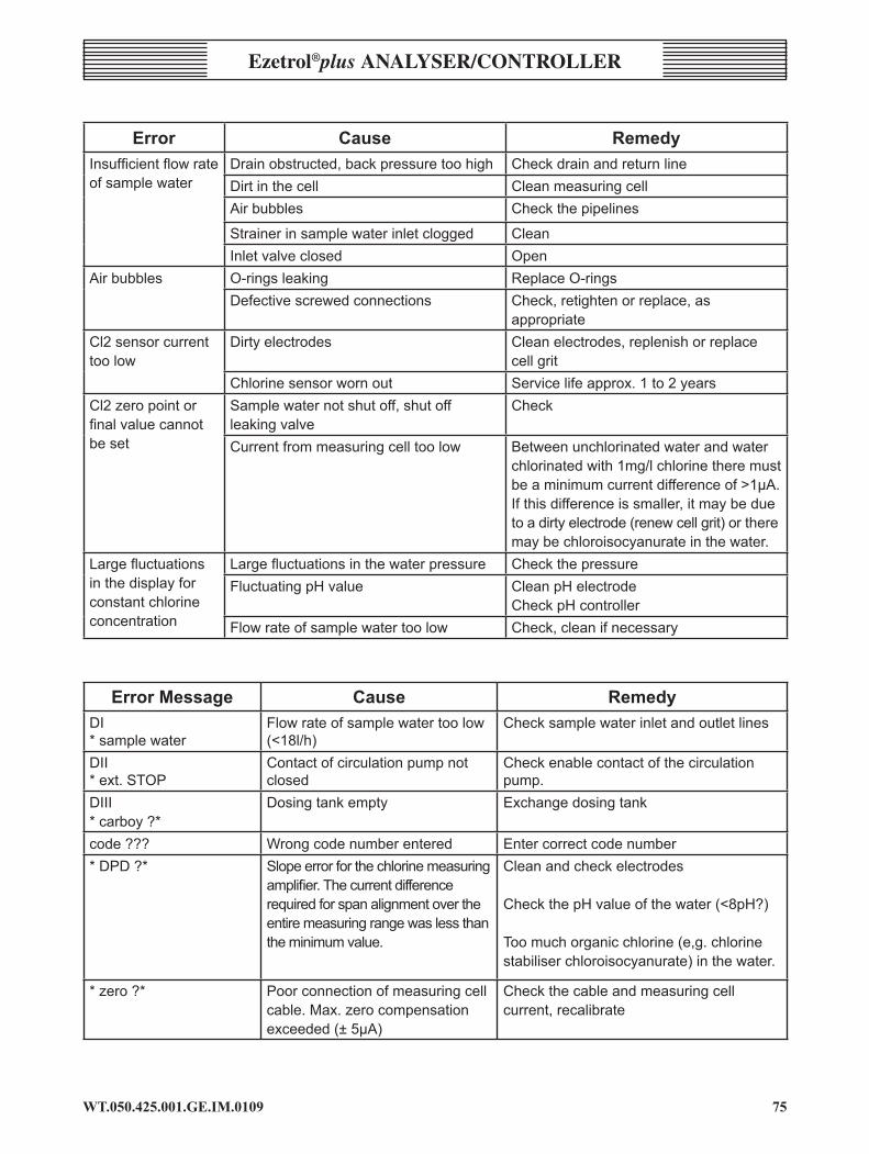
�5WT.050.425.00�.GE.IM.0�09
Ezetrol®plus analysEr/controllEr
error cause RemedyInsufficient flow rate ofsamplewater
Drainobstructed,backpressuretoohigh CheckdrainandreturnlineDirtinthecell CleanmeasuringcellAirbubbles Checkthepipelines
Strainerinsamplewaterinletclogged CleanInletvalveclosed Open
Airbubbles O-ringsleaking ReplaceO-ringsDefectivescrewedconnections Check,retightenorreplace,as
appropriateCl2sensorcurrenttoolow
Dirtyelectrodes Cleanelectrodes,replenishorreplacecellgrit
Chlorinesensorwornout Servicelifeapprox.1to2yearsCl2zeropointorfinal value cannot beset
Samplewaternotshutoff,shutoffleakingvalve
Check
Currentfrommeasuringcelltoolow Betweenunchlorinatedwaterandwaterchlorinatedwith1mg/lchlorinetheremustbeaminimumcurrentdifferenceof>1µA.Ifthisdifferenceissmaller,itmaybeduetoadirtyelectrode(renewcellgrit)ortheremaybechloroisocyanurateinthewater.
Large fluctuations inthedisplayforconstantchlorineconcentration
Large fluctuations in the water pressure CheckthepressureFluctuatingpHvalue CleanpHelectrode
CheckpHcontrollerFlowrateofsamplewatertoolow Check,cleanifnecessary
ErrorMessage cause RemedyDI*samplewater
Flowrateofsamplewatertoolow(<18l/h)
Checksamplewaterinletandoutletlines
DII*ext.STOP
Contactofcirculationpumpnotclosed
Checkenablecontactofthecirculationpump.
DIII*carboy?*
Dosingtankempty Exchangedosingtank
code??? Wrongcodenumberentered Entercorrectcodenumber*DPD?* Slopeerrorforthechlorinemeasuring
amplifier. The current difference requiredforspanalignmentovertheentiremeasuringrangewaslessthantheminimumvalue.
Cleanandcheckelectrodes
CheckthepHvalueofthewater(<8pH?)
Toomuchorganicchlorine(e,g.chlorinestabiliserchloroisocyanurate)inthewater.
*zero?* Poorconnectionofmeasuringcellcable.Max.zerocompensationexceeded(±5µA)
Checkthecableandmeasuringcellcurrent,recalibrate
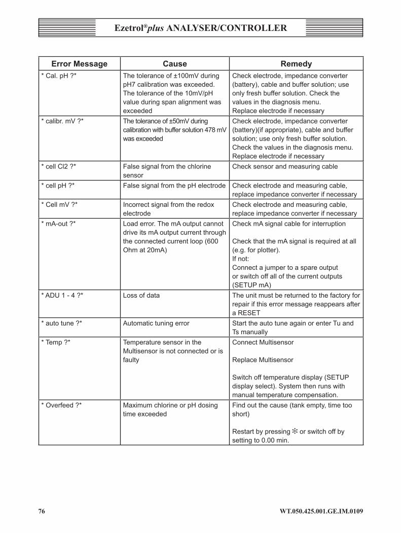
WT.050.425.00�.GE.IM.0�09��
Ezetrol®plus analysEr/conTrollEr
ErrorMessage cause Remedy*Cal.pH?* Thetoleranceof±100mVduring
pH7calibrationwasexceeded.Thetoleranceofthe10mV/pHvalueduringspanalignmentwasexceeded
Checkelectrode,impedanceconverter(battery),cableandbuffersolution;useonlyfreshbuffersolution.Checkthevaluesinthediagnosismenu.Replaceelectrodeifnecessary
*calibr.mV?* Thetoleranceof±50mVduringcalibrationwithbuffersolution478mVwasexceeded
Checkelectrode,impedanceconverter(battery)(ifappropriate),cableandbuffersolution;useonlyfreshbuffersolution.Checkthevaluesinthediagnosismenu.Replaceelectrodeifnecessary
*cellCl2?* Falsesignalfromthechlorinesensor
Checksensorandmeasuringcable
*cellpH?* FalsesignalfromthepHelectrode Checkelectrodeandmeasuringcable,replaceimpedanceconverterifnecessary
*CellmV?* Incorrectsignalfromtheredoxelectrode
Checkelectrodeandmeasuringcable,replaceimpedanceconverterifnecessary
*mA-out?* Loaderror.ThemAoutputcannotdriveitsmAoutputcurrentthroughtheconnectedcurrentloop(600Ohmat20mA)
CheckmAsignalcableforinterruption
CheckthatthemAsignalisrequiredatall(e.g.forplotter).Ifnot:Connectajumpertoaspareoutputorswitchoffallofthecurrentoutputs(SETUPmA)
*ADU1-4?* Lossofdata TheunitmustbereturnedtothefactoryforrepairifthiserrormessagereappearsafteraRESET
*autotune?* Automatictuningerror StarttheautotuneagainorenterTuandTsmanually
*Temp?* TemperaturesensorintheMultisensorisnotconnectedorisfaulty
ConnectMultisensor
ReplaceMultisensor
Switchofftemperaturedisplay(SETUPdisplayselect).Systemthenrunswithmanualtemperaturecompensation.
*Overfeed?* MaximumchlorineorpHdosingtimeexceeded
Findoutthecause(tankempty,timetooshort)
Restartbypressing[orswitchoffbysettingto0.00min.
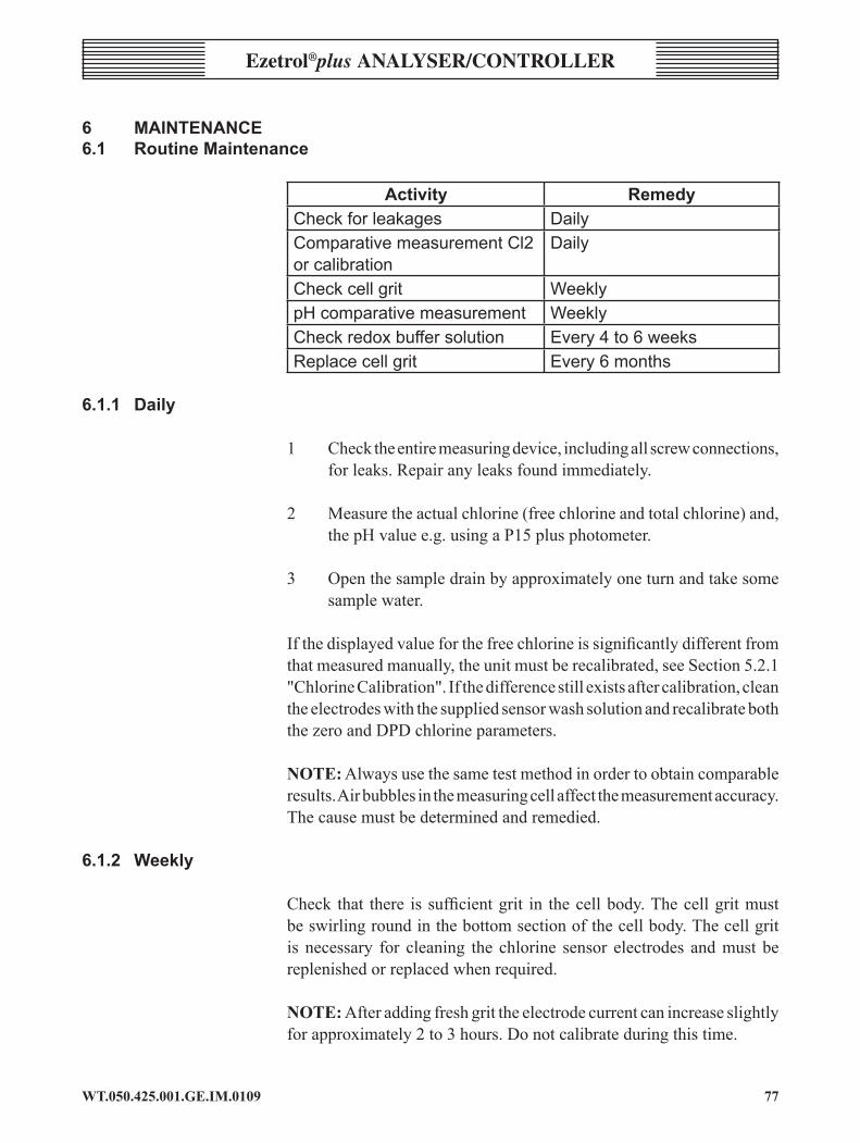
��WT.050.425.00�.GE.IM.0�09
Ezetrol®plus analysEr/controllEr
6 MAINTENANCE6.1 RoutineMaintenance
activity RemedyCheckforleakages DailyComparativemeasurementCl2orcalibration
Daily
Checkcellgrit WeeklypHcomparativemeasurement WeeklyCheckredoxbuffersolution Every4to6weeksReplacecellgrit Every6months
6.1.1 Daily
1 Checktheentiremeasuringdevice,includingallscrewconnections,forleaks.Repairanyleaksfoundimmediately.
2 Measuretheactualchlorine(freechlorineandtotalchlorine)and,thepHvaluee.g.usingaP15plusphotometer.
3 Openthesampledrainbyapproximatelyoneturnandtakesomesamplewater.
Ifthedisplayedvalueforthefreechlorineissignificantlydifferentfromthatmeasuredmanually,theunitmustberecalibrated,seeSection5.2.1"ChlorineCalibration".Ifthedifferencestillexistsaftercalibration,cleantheelectrodeswiththesuppliedsensorwashsolutionandrecalibrateboththezeroandDPDchlorineparameters.
noTE:Alwaysusethesametestmethodinordertoobtaincomparableresults.Airbubblesinthemeasuringcellaffectthemeasurementaccuracy.Thecausemustbedeterminedandremedied.
6.1.2 Weekly
Check that there issufficientgrit in thecellbody.Thecellgritmustbeswirlingroundinthebottomsectionofthecellbody.Thecellgritis necessary for cleaning the chlorine sensor electrodes andmust bereplenishedorreplacedwhenrequired.
noTE: Afteraddingfreshgrittheelectrodecurrentcanincreaseslightlyforapproximately2to3hours.Donotcalibrateduringthistime.
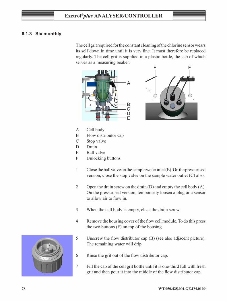
WT.050.425.00�.GE.IM.0�09��
Ezetrol®plus analysEr/conTrollEr
6.1.3 Sixmonthly
Thecellgritrequiredfortheconstantcleaningofthechlorinesensorwearsitsselfdownintimeuntilitisveryfine.Itmustthereforebereplacedregularly.Thecellgritissuppliedinaplasticbottle,thecapofwhichservesasameasuringbeaker. F F A
B C D E
A CellbodyB FlowdistributorcapC Stop valveD DrainE Ball valveF Unlockingbuttons
1 Closetheballvalveonthesamplewaterinlet(E).Onthepressurisedversion,closethestopvalveonthesamplewateroutlet(C)also.
2 Openthedrainscrewonthedrain(D)andemptythecellbody(A).Onthepressurisedversion,temporarilyloosenaplugorasensortoallowairtoflowin.
3 Whenthecellbodyisempty,closethedrainscrew.
4 Removethehousingcoveroftheflowcellmodule.Todothispressthetwobuttons(F)ontopofthehousing.
5 Unscrewtheflowdistributorcap(B)(seealsoadjacentpicture).Theremainingwaterwilldrip.
6 Rinsethegritoutoftheflowdistributorcap.
7 Fillthecapofthecellgritbottleuntilitisone-thirdfullwithfreshgritandthenpouritintothemiddleoftheflowdistributorcap.

�9WT.050.425.00�.GE.IM.0�09
Ezetrol®plus analysEr/controllEr
8 Screwtheflowdistributorcapbackon.
9 Opentheballvalveonthesamplewaterinletand,ifappropriate,openthestopvalveonthesamplewaterreturnline.Thecellbodyfillswithsamplewater.Arotatingairbubbledoesnotaffectthemeasurements,itdisappearsonitsown.
10 Replacethehousingcoverandclickintoplace.
11 After2to3hoursrunning-intimeperformachlorinecaslibration.Ifnecessary,repeatthechlorinecalibrationafter24hours.
6.2 ChangingtheFuse,BatteryorMultisensor
WarnInG:Disconnect the power supply before opening the unit.Only trained electricians are authorised to open the housing.MorecomplicatedrepairsmustbecarriedoutbySiemensWaterTechnologiesservicetechnicians.
6.2.1 Replacingthefuse
1 Disconnecttheunitfromthepowersupply.
2 Removethecoveroftheelectronicmoduleandunplugtheconnectioncabletothemotherboard.
3 Checkthefuses,replaceifnecessary.F1,F2fuse0.63AT.Twosparefusesareprovidedonthesideoftheunit.
4 Plugintheconnectioncableandreplacethecover.
6.2.2 Replacingthebattery
If the clock stops1 Disconnecttheunitfromthepowersupply.
2 Removetheelectronicmodulecoverandunplugtheconnectioncabletothemotherboard.
3 Replacethebattery;(PartNo.E-100397).
4 Plugintheconnectioncableandreplacethecover.

WT.050.425.00�.GE.IM.0�09�0
Ezetrol®plus analysEr/conTrollEr
A BatteryB F1,F2C Spare fuse
6.2.3 ChangingtheMultisensor
Iftemperaturemeasurementorsamplewatermonitoringfails:-
1 Shutoffthesamplewater.
2 Disconnecttheunitfromthepowersupply.
3 Removethecoveroftheelectronicmoduleandunplugtheconnectioncabletothemotherboard.
4 Removethecoveroftheflowcellmodule.
5 PresstheredringsurroundingtheMultisensorinthenpullitoutagain.
6 Disconnectthesensorcablefromthemotherboard.
7 Installthenewsensorinthereverseorder.
8 Insertthesensorcablewiththeattachedbushintothecableductsofthehousing.
9 Closebothhousingcovers.Multisensor

��WT.050.425.00�.GE.IM.0�09
Ezetrol®plus analysEr/controllEr
7 spare parts7.1 FlowCellModuleandSensors
caUTIon: Forsafety reasons,onlyuseoriginalspareparts.PleasecontactSiemensWaterTechnologiesAfterSales department for anysparepartsenquiries/orders.
sensorsfreechlorine pH redox
spare partsSensor AAC4807 U95690 U95691Cable0.9m AAC5257 - AAD2056ConsumablesCalibrationsolutionBottle250ml
- - 478mVE-100278
Calibrationsolution12.5mlsachet
pH7.00EXA-100476pH4.65EXB-100476
478mVEXA-100477
KClreservoirKClsolution5ml
AAC4084 AAC4084 AAC4084
ElectrolytesolutionBottle250ml
AAB3547 AAB3547 AAB3547
Cellgrit U-93275 - -Beaker 1unit: AAC5587
75units: AAC5590Extensioncable 1connector 2connectors 2connectors
5m10m15m25m50m
AAC5260AAC5263AAC5827AAC5830AAC5833
AAC5269AAC5272AAC5818AAC5821AAC5824
AAC5269AAC5272AAC5818AAC5821AAC5824
Impedanceconverter - U-95607 U-95607
7.2 ElectronicModule
spare partsLabellingstrips Cl2+pH,Cl2+pH+mV AAC4555Anti-surgefuse0.63A for200-240V/100-120V AAC8989Battery E-100397Coverwithdisplay AAD2101Accessoriesset 4cableterminalscrews AAD2131
log Printer
spare parts forW&Tlogprinter,modeltallyT2024/9(AAC5998)Spareinkribbon AAC6004Printercable3m AAC5887Printercable15m AAC5914
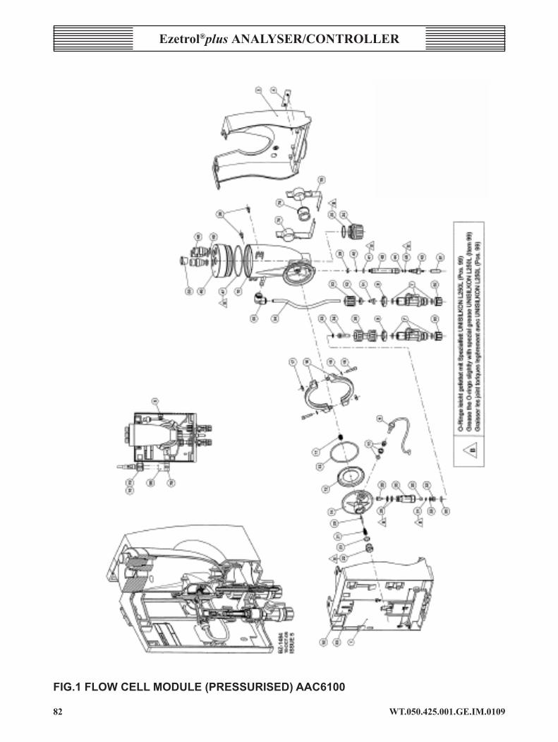
WT.050.425.00�.GE.IM.0�09�2
Ezetrol®plus analysEr/conTrollEr
FIG.1FLOWCELLMODULE(PRESSURISED)AAC6100

��WT.050.425.00�.GE.IM.0�09
Ezetrol®plus analysEr/controllEr
Item PartNo. Description 1 AAC5908 Basichousing,pre-assembled 2 P-95408 Typeplate 3 AAC4615 Housingcover 4 AAD2041 Productlabel 5 AAC5374 Cableclamp 6 AAC5461 Multisensor 7 AAC5602 Shut-offvalve 9 AAC4891 Flatnut 10 AAC4762 Cellbody 11 AAA6982 Compressionspring 12 AAC4828 Membraneunit 13 AAC4885 O-ringd76x3/EPDM 14 AAC5371 Controlvalvebody 15 AAC4999 Plasticcartridge 16 AAC4777 Vprofileclamp 17 AAC4801 Squarenut 18 PXE-95248 Cylinderscrew 19 P-92697 Washer 20 AAC4840 Valvepin 21 P-44580-G Compressionspring 22 AAC4843 Adjustingscrew 23 AAA5537 O-ringd13x2/EPDM 24 AAC4780 Flowdistributorcap 25 AAC4888 O-ringd32x1.5/EPDM 26 AAC4774 Checkvalvehousing 28 P-92571 O-ringd12x1.5/FPM 29 AAA7051 Cone 30 PXA-95859 Ball 31 PXA-95968 O-ringd4.47x1.78/EPDM 32 PXA-95234 Insert 33 PXB-95968 O-ringd8x1.5/EPDM 34 AAC4852 Finefilter 35 AAC5605 Filterhousing 36 AAD5860 Panheadscrew 39 AAC5596 Securingring 40 AAC4861 Outletdrainpipe 41 PXC-95968 O-ringd8x2/EPDM 42 AAC7126 O-ringd5x1.5/EPDM 43 AAC4858 Drainscrew 44 AAC9550 Flatgasket 45 PXA-33051 O-ringd5.28x1.78/EPDM 46 AAC4789 Cellbodycover 47 AAC4906 O-ringd84x2/EPDM 48 P-96215 Plug 49 P-100438 O-ringd13x2.5/FPM 50 P-94734 O-ringd11.3x2.4/FPM 51 PXA-95542 Hosebushing 52 AAA6901 Lockingring 53 PXA-95702 Unionnut 54 AAC5599 Hose 55 AAC4996 Angle-reducingconnector
Item PartNo. Description 78 AAC5581 Fasteningclip,coated 79 AAC5662 Electrodemount 80 PXD-97335 Screwcap 81 AAC2551 Protectivecap 83 P-96260 Protectionplug 92 AAC4609 Wallbrackets 93 PXB-94077 Sheetmetalscrew 98 AAC5587 Beaker
Pre-assembledcomponentspart no. description consistingof:AAC5614 Cellbody,
completeItems10-25,47-49,83
AAC5608 Non-returnvalve
Items26,28-33,50,80
AAC5611 Drainageunit Items39-45,81AAC6277 Fine filter Items33-34UXA-95548 Spherical
seatItems31-33
Spare part sets part no. designation consistingof:AAC5800 Spareparts
set,basickitItems7,12,13,16-1923,25,28,31-33,41,42,44,45,47,49,50SpecialgreaseUNISILKONL250L(8mltube,AAC7189)
AAC7210 Sparepartssetfor2yearsofoperation
CellgritU-93275(2)measuringbeakerAAC5590(75pcs.),V profile clamps (2x itemNo.16)
AAC7213 Sparepartssetfor5yearsoperation
CellgritU-93275(2)measuringbeakerAAC5590(75pcs.),V profile clamps (2x itemNo.16)
FIG.1FLOWCELLMODULE(PRESSURISED)AAC6100
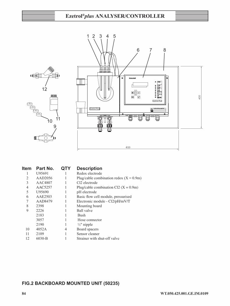
WT.050.425.00�.GE.IM.0�09�4
Ezetrol®plus analysEr/conTrollEr
Item PartNo. QTY Description 1 U95691 1 Redoxelectrode 2 AAD2056 1 Plug/cablecombinationredox(X=0.9m) 3 AAC4807 1 Cl2electrode 4 AAC5257 1 Plug/cable combination Cl2 (X = 0.9m) 5 U95690 1 pHelectrode 6 AAE2503 1 Basic flow cell module, pressurised 7 AAD8479 1 Electronic module - Cl2/pH/mV/T 8 2398 1 Mountingboard 9 2226 1 Ballvalve 2183 1 Bush 3057 1 Hoseconnector 2190 1 ½"nipple 10 4052A 4 Boardspacers 11 2109 1 Sensorcleaner 12 6030-B 1 Strainerwithshut-offvalve
1 2 3 4 5
6 7 8
910 11
12
FIG.2BACKBOARDMOUNTEDUNIT(50235)

�5WT.050.425.00�.GE.IM.0�09
Ezetrol®plus analysEr/controllEr
Mains Voltage Analog Outputs Interfaces
Inputs General Measuring Inputs (sensor)
L1 N/L2 mA1 mA2 mA3 RS232 RS485
+ - + - + - B A 7 8 9 10 11 12 13 14 15 32 33 29 30 31
3 2 1
L1 N/L2 PE 0/4...20mA RS232 Load Max: 600 Ohm Printer
Supply W&T-RS485-Interface 230/115V AC for CMS ChemWeb Server etc.
Digital Input Temperature Cl2 pH Redox PT100TX
D
GN
D
DI1 DI2 DI3
1 2 3 4 5 6 34 35 25 21 22 23 27 21 22 23 16 17
WR
K
REF
CN
T
WH YE
BN GN PT1000
Control Container Sample Water Cl2 pH Redox PT100 Stop Empty Control/ Temperature
RD
WH
BL
YE GN W B
FIG.3WIRINGDIAGRAM(SHEET150234)
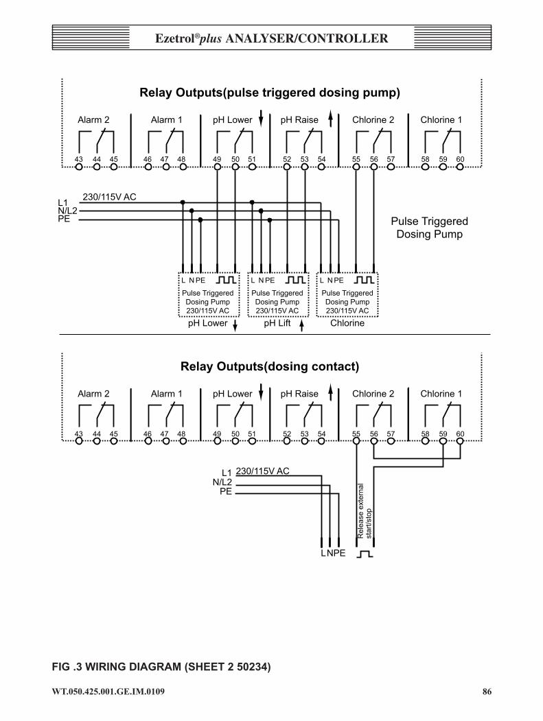
��WT.050.425.00�.GE.IM.0�09
Ezetrol®plus analysEr/controllEr
L N PE
Pulse TriggeredDosing Pump230/115V AC
pH Lower
L N PE
Pulse TriggeredDosing Pump230/115V AC
pH Lift
L N PE
Pulse TriggeredDosing Pump230/115V AC
Chlorine
Relay Outputs(pulse triggered dosing pump)
Alarm 2 Alarm 1 pH Lower pH Raise Chlorine 2 Chlorine 1
Pulse TriggeredDosing Pump
Relay Outputs(dosing contact)
Alarm 2 Alarm 1 pH Lower pH Raise Chlorine 2 Chlorine 1
230/115V ACL1N/L2PE
43 44 45 46 47 48 49 50 51 52 53 54 55 56 57 58 59 60
43 44 45 46 47 48 49 50 51 52 53 54 55 56 57 58 59 60
L1N/L2
PE
230/115V AC
L N PE
Rel
ease
ext
erna
lst
art/s
top
FIG.3WIRINGDIAGRAM(SHEET250234)
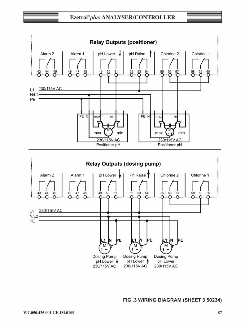
��WT.050.425.00�.GE.IM.0�09
Ezetrol®plus analysEr/controllEr
PE N max min
max min
230/115V ACPositioner pH
M~ 1
PE N max min
max min
230/115V ACPositioner pH
M~ 1
Relay Outputs (positioner)
Alarm 2 Alarm 1 pH Lower pH Raise Chlorine 2 Chlorine 1
43 44 45 46 47 48 49 50 51 52 53 54 55 56 57 58 59 60
230/115V ACL1N/L2PE
M1 ~
L1 N PE
Dosing PumppH Lower
230/115V AC
M1 ~
L1 N PE
Dosing PumppH Lower
230/115V AC
M1 ~
L1 N PE
Dosing PumppH Lower
230/115V AC
Relay Outputs (dosing pump)
43 44 45 46 47 48 49 50 51 52 53 54 55 56 57 58 59 60
230/115V ACL1N/L2PE
Alarm 2 Alarm 1 pH Lower Ph Raise Chlorine 2 Chlorine 1
FIG.3WIRINGDIAGRAM(SHEET350234)


