58
UAIS TRANSPONDER FA-100
| Date post: | 05-Apr-2018 |
| Category: |
Documents |
| Upload: | kostasxave |
| View: | 234 times |
| Download: | 0 times |

7/31/2019 FA100 Installation Manual h3 10.25
http://slidepdf.com/reader/full/fa100-installation-manual-h3-1025 1/58
UAIS TRANSPONDER
FA-100

7/31/2019 FA100 Installation Manual h3 10.25
http://slidepdf.com/reader/full/fa100-installation-manual-h3-1025 2/58
Your Local Agent/Dealer Your Local Agent/Dealer
9-52 Ashihara-cho,9-52 Ashihara-cho,
Nishinomiya 662-8580, JAPANNishinomiya 662-8580, JAPAN
Telephone :Telephone : 0798-65-21110798-65-2111
7/31/2019 FA100 Installation Manual h3 10.25
http://slidepdf.com/reader/full/fa100-installation-manual-h3-1025 3/58
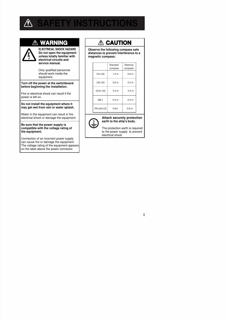
SAFETY INSTRUCTIONS
Turn off the power at the switchboardbefore beginning the installation.
Fire or electrical shock can result if thepower is left on.
Do not install the equipment where itmay get wet from rain or water splash.
Water in the equipment can result in fire,electrical shock or damage the equipment.
Be sure that the power supply iscompatible with the voltage rating ofthe equipment.
Connection of an incorrect power supplycan cause fire or damage the equipment.The voltage rating of the equipment appearson the label above the power connector.
ELECTRICAL SHOCK HAZARD
Do not open the equipment
unless totally familiar withelectrical circuits andservice manual.
Only qualified personnelshould work inside theequipment.
Observe the following compass safedistances to prevent interference to a
magnetic compass:
Standard
compass
Steering
compass
FA-100 1.0 m 0.6 m
CB-100 0.6 m 0.4 m
GVA-100 0.3 m 0.3 m
DB-1 0.3 m 0.3 m
PR-240-CE 0.9m 0.6 m
Attach securely protectionearth to the ship's body.
The protection earth is requiredto the power supply to preventelectrical shock

7/31/2019 FA100 Installation Manual h3 10.25
http://slidepdf.com/reader/full/fa100-installation-manual-h3-1025 4/58
TABLE OF CONTENTS
SYSTEM CONFIGURATION................................................................................ iii
EQUIPMENT LISTS ............................................................................................. iv
1. MOUNTING ....................................................................................................... 1
1.1 Antenna Unit....................................................................................................................1
1.1.1 GPS antenna unit ...............................................................................................1
1.1.2 VHF antenna ......................................................................................................3
1.1.3 GPS/VHF combined antenna ..............................................................................5
1.2 Transponder Unit.............................................................................................................8
1.3 Junction Box..................................................................................................................10
1.4 Power Supply (option) ...................................................................................................11
1.5 Pilot Plug (option) ..........................................................................................................11
2. WIRING ........................................................................................................... 12
3. INPUT/OUTPUT SIGNAL ............................................................................... 15
3.1 Inputs from Sensors.......................................................................................................15
3.2 Input/Output of AIS Signal .............................................................................................16
3.3 Input of Gyrocompass Signal.........................................................................................17
3.4 Alarm Signal Output.......................................................................................................173.5 LAN Input/Output...........................................................................................................18
3.6 Pilot Plug.......................................................................................................................18
3.7 Jumper Setting in the Junction Box................................................................................19
3.8 Input/Output Sentences.................................................................................................20
3.9 Changing Ship’s Mains Specifications............................................................................21
4. SETTING AND ADJUSTMENT....................................................................... 224.1 Setting MMSI IMO No., Name and Call Sign .................................................................22
4.2 Setting GPS Antenna Position and Ship’s Type .............................................................24
4.3 System Settings.............................................................................................................26
PACKING LIST

7/31/2019 FA100 Installation Manual h3 10.25
http://slidepdf.com/reader/full/fa100-installation-manual-h3-1025 5/58
SYSTEM CONFIGURATION
: Standard : Option
GPS/VHF
combined antennaGVA-100
GPS antennaGPA-017S
GSC-001
Distributor unitDB-1
VHF whip antenna
Transponder unitFA-100
Junction box CB-100
Other external equipments
Power supplyPR-240-CE
Ship's mains
Either
GPS Navigator *
Gyrocompass
AD-100

7/31/2019 FA100 Installation Manual h3 10.25
http://slidepdf.com/reader/full/fa100-installation-manual-h3-1025 6/58
EQUIPMENT LISTS
Standard supplyNo. Name Type Code no. Qty Remarks
1 Transponder Unit FA-100 - 1
2 Junction Box CB-100 - 1
GPS Antenna GPA-017S -
GPS Antenna GSC-001 -
3
GPS/VHF Combined Antenna
GVA-100* - 1 Select one.
CP24-00101* 005-950-730 1 For DB-1
CP24-00102* 005-950-700 1 For FA-100
CP05-08701* 005-949-280 1 For CB-100
CP24-00121** 005-952-350 1 For GPA-017S
4 Installation Materials
CP24-00141* 005-952-330 1 For GVA-100
**: for Japan only
Optional supplyNo. Name Type Code no. Remarks
1 Antenna cable set CP20-01700(30m) 004-372-110 For GPS or Combined antenna
8D-FB-CV *30M*, CP20-017012 Antenna cable set CP20-01710(50m) 004-372-120 For GPS or Combined antenna
8D-FB-CV *50M*, CP20-01701
3 Flush mount kit A OP24-1 005-950-740
4 Flush mount kit B OP24-2 005-950-750
5 Mast mount fixture CP20-01111 004-365-780 For GPA-017S
6 Right-angleantenna base
No.13-QA330 000-803-239 For GPA-017S
7 L-angle antennabase
No.13-QA310 000-803-240 For GPA-017S
8 Antenna base for rail mount
No.13-RC5160 000-806-114 For GPA-017S
9 VHF whip antenna FAB 151D 000 572 029 For Japan only

7/31/2019 FA100 Installation Manual h3 10.25
http://slidepdf.com/reader/full/fa100-installation-manual-h3-1025 7/58
1. MOUNTING
1.1 Antenna Unit
1.1.1 GPS antenna unit
Install the GPS antenna unit referring to the drawing at the back of this manual D-1.
When selecting a mounting location for the antenna, keep in mind the followingpoints.
• Select a location out of the radar beam. The radar beam will obstruct or prevent
reception of the GPS satellite signal.
• There should be no interfering object within the line-of-sight to the satellites. Objects
within line-of-sight to a satellite, for example, a mast, may block reception or prolong
acquisition time.
• Mount the antenna unit as high as possible to keep it free of interfering objects and
water spray, which can interrupt reception of GPS satellite signal if the water freezes.
Extending antenna cable
Three types of antenna cable extensions are optionally available.
a) Antenna cable set CP20-01700
Antenna Unit
1 m
Antenna Cable
30 m 1 m
Fabricate locally. (See next page.)
FA-100
: ConnectorConversionCable Assy.
NJ-TP-3DXV-10.6 m
◆ Waterproofing connector
Wrap connector with vulcanizing tape and then vinyl tape. Bind the tape end with
a cable-tie.

7/31/2019 FA100 Installation Manual h3 10.25
http://slidepdf.com/reader/full/fa100-installation-manual-h3-1025 8/58
How to attach the connector N-P-8DFB for cable 8D-FB-CV
Outer SheathArmor
Dimensions in millimeters.
Inner Sheath Shield
Remove outer sheath and armor by the dimensions
shown left.Expose inner sheath and shield by the dimensionsshown left.
Cut off insulator and core by 10mm.
Twist shield end.
Ship on clamp nut, gasket and clamp as shown left.
Fold back shield over clamp and trim.
Cut aluminum foil at four places, 90° from one
another.
Fold back aluminum foil onto shield and trim.
Expose the insulator by 1mm.
Expose the core by 5mm.
Slip the pin onto the conductor. Solder them together
Cover with heat-shrink tubing and heat.
30 10
ClampNut
Gasket(reddishbrown)
Clamp
Aluminum Foil
Trim shield here.
Trim aluminumtape foil here.
Insulator
1
5
Pin
50 30

7/31/2019 FA100 Installation Manual h3 10.25
http://slidepdf.com/reader/full/fa100-installation-manual-h3-1025 9/58
1.1.2 VHF antenna
Location
Location of the mandatory AIS VHF-antenna should be carefully considered. Digital
communication is more sensitive than analog/voice communication to interference
created by reflections in obstructions like masts and booms. It may be necessary to
relocate the VHF radiotelephone antenna to minimize interference effects.
To minimise interference effects, the following guidelines apply:
• The AIS VHF antenna should be placed in an elevated position that is as free as
possible with a minimum of 0.5 meters in the horizontal direction from constructions
made of conductive materials. The antenna should not be installed close to any large
vertical obstruction. The objective for the AIS VHF antenna is to see the horizon
freely through 360 degrees.
• The AIS VHF antenna should be installed safely away from interfering high-power
energy sources like radar and other transmitting radio antennas, preferably at least 3
meters away from and out of the transmitting beam.
• There should not be more than one antenna on the same plane. The AIS VHF
antenna should be mounted directly above or below the ship’s primary VHF
radiotelephone antenna, with no horizontal separation and with a minimum of 2.8
meters vertical separation. If it is located on the same plane as other antennas, the
distance apart should be at least 10 meters.
Cabling
•The cable should be kept as short as possible to minimize signal attenuation.Coaxial cables equal to or better than RG10U/Y are recommended.
• All outdoor installed connectors on coaxial cables should be fitted with preventive
isolation such as vulcanizing tape to protect against water penetration into the
antenna cable.
•
Coaxial cables should be installed in separate signal cable channels/tubes and atleast 10 cm away from power supply cables. Crossing of cables should be done at
right angles (90°). The minimum bend radius of the coaxial cable should be 5 times
the cable's outer diameter.
• Install the VHF whip antenna referring to the outline drawing at the back of this

7/31/2019 FA100 Installation Manual h3 10.25
http://slidepdf.com/reader/full/fa100-installation-manual-h3-1025 10/58
• When coaxial cable RG-10U/Y (shipyard supply) is used, attach the coaxial plug
M-P-7 (dockyard supply) as shown on the next page.
Horizontal separation distance
More than 10 m
More than 0.5 m
More than2.8 m
Vertical separation distance
Other VHF whip antenna
Whip antenna for AIS
(GPS/VHF combinedantenna)

7/31/2019 FA100 Installation Manual h3 10.25
http://slidepdf.com/reader/full/fa100-installation-manual-h3-1025 11/58
How to attach the plug M-P-7
Lay the coaxial cable and attach an M-type plug (if necessary) to the cable as
follows.
1. Remove the sheath by 30 mm.
2. Bare 23 mm of the center conductor. Trim
braided shield by 5 mm and tin.
3. Slide coupling ring onto cable.
4. Screw the plug assembly on the cable.
5. Solder plug assembly to braided shield
through solder holes. Solder contact sleeveto conductor.
6. Screw coupling ring into plug assembly.
1.1.3 GPS/VHF combined antennaInstall the combined antenna unit referring to the outline drawing. When selecting a
mounting location for the antenna, keep in mind the following points.
• Select a location out of the radar beam. The radar beam will obstruct or prevent
reception of the GPS satellite signal.
• There should be no interfering object within the line-of-sight to the satellites. Objects
within line-of-sight to a satellite, for example, a mast, may block reception or prolong
acquisition time.
• Mount the antenna unit as high as possible. Mounting it this way keeps it free of
interfering objects and water spray, which can interrupt reception of GPS satellite
signal if the water freezes.
• Also, refer to the antenna installation guidelines page 3.
Outdoor Indoor
Di t ib t DB 1
Sheath
30 mm
5 mm 2 mm
Conductor
InsulatorBraided shield
Plug assembly Contact sleeve
Cut conductor here.Solder both
sides of hole.Coupling ring

7/31/2019 FA100 Installation Manual h3 10.25
http://slidepdf.com/reader/full/fa100-installation-manual-h3-1025 12/58
Mounting procedures
1. Dismount the bottom cover, cut the cable-tie inside the unit and take out the
coaxial connector attached to the combined box.
2. Loosen four screws to loosen whip antenna fixture and pull out the coaxialconnector coming from the combined box through the hole in the whip antenna
fixture.
3. Connect the coaxial connector to the whip antenna base and wrap the junction
part of the whip antenna with vulcanizing tape and then vinyl tape for
waterproofing.
4. Insert the whip antenna from the top of the combined antenna.
5. Secure the whip antenna with whip antenna fixture.6. Using a new plastic band (supplied), secure the cables and coaxial connector
inside the antenna case.
7. Mount the bottom cover.
8. Fix the GPS/VHF combined antenna to the ship’s stanchion (40 to 50 mm
diameter) with antenna fixing brackets, flat washers and hex. nuts.
Note: Coat the exposed parts of bolts and nuts with silicon sealant.
Whip antenna fixture
Antenna fixing bracket
Bottom cover
Combined box
Loosen four screws.
(M5x16)
GPS/VHF Combined antenna

7/31/2019 FA100 Installation Manual h3 10.25
http://slidepdf.com/reader/full/fa100-installation-manual-h3-1025 13/58
Stanchion
The top of the stanchion come
into contact with the flange.
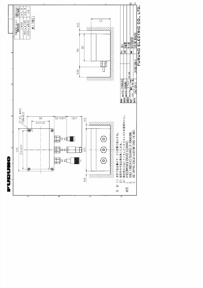
Installing distributor unit DB-1The length of the cable between the distributor unit and transponder unit is 1 m so
locate the distributor unit within 1 m from the transponder unit. Fix the distributor
unit on the bulkhead, facing the cable entrance downward. Remove the lid of the
distributor unit and secure the unit with two tapping screws.
Tapping screw(4x30)

7/31/2019 FA100 Installation Manual h3 10.25
http://slidepdf.com/reader/full/fa100-installation-manual-h3-1025 14/58
1.2 Transponder Unit
The transponder unit can be installed on a desktop or flush mounted in a panel.
Install it on the chart table or near the steering place, referring to the outline
drawing.
When selecting a mounting location for the transponder, keep the following in mind:
• Keep the transponder out of direct sunlight.
• The temperature and humidity should be moderate and stable.
(Operating temperature range: -15°C to +55°C)
• Locate the unit away from exhaust pipes and vents.
• The mounting location should be well ventilated.
• Mount the unit where shock and vibration are minimal.
• Keep the unit away from electromagnetic field generating equipment such as
motor, generator.
• For maintenance and checking purposes, leave sufficient space at the sides and
rear of the unit and leave slack in cables. Refer to the outline drawing.
• A magnetic compass will be affected if the unit is placed too close to it. Observe
the following compass safe distances to prevent disturbance to the magnetic
compass:
Standard compass: 1.0 meters
Steering compass: 0.6 meters
Desktop mounting
1. Remove two hex. bolts from the lower part of the transponder unit and dismount
the mounting base.
2. Fix the mounting base to the desktop with four tapping screws (6x20: supplied)
or hex. bolts.
Remove two hex. bolts.
120 mm120 mm

7/31/2019 FA100 Installation Manual h3 10.25
http://slidepdf.com/reader/full/fa100-installation-manual-h3-1025 15/58
Flush mounting
Optional flush mount kit A or B is required for flush mounting. For mounting
dimensions, refer to the outline drawing at the back of this manual.
Flush mount kit A: Type OP24-1 Code no. 005-950-740
Name Type Code no. Qty
1 Cosmetic panel 24-003-2811 100-299-540 1
2 +Tapping screw 5x25 000-802-082 4
1. Cut out a hole in the mounting location, referring to the outline drawing.2. Remove two hex bolts to dismount the mounting base.
3. Remove six hex bolts from the bottom of the transponder unit to dismount the
mounting pedestal.
4. Set the transponder unit to the cosmetic panel and fix them with six hex bolts.
5. Set the assembly (transponder unit and cosmetic panel) to the hole and fix it
with four tapping screws (5x25).
Flush mount kit B: Type OP24-2 Code no. 005-950-750
Name Type Code no. Qty
1 Mounting bracket 24-003-2821 100-299-550 1
2 Hex bolt M5x25 000-862-125 6
3 Hex nut M5 000-863-108 6
4 Flat washer M5 000-864-128 6
5 Spring washer M5 000-864-258 6
1. Cut out a hole in the mounting location, referring to the outline drawing.
2. Dismount the mounting base and mounting pedestal from the transponder unit.
3. Set the transponder unit to the hole. Using six hex bolts, attach the mounting
bracket at the bottom of the transponder unit from the rear of the flush mounting
panel.
4. Fix with six sets of hex bolt, nut, flat washers and spring washers from the rear
of the flush mounting panel.
7/31/2019 FA100 Installation Manual h3 10.25
http://slidepdf.com/reader/full/fa100-installation-manual-h3-1025 16/58
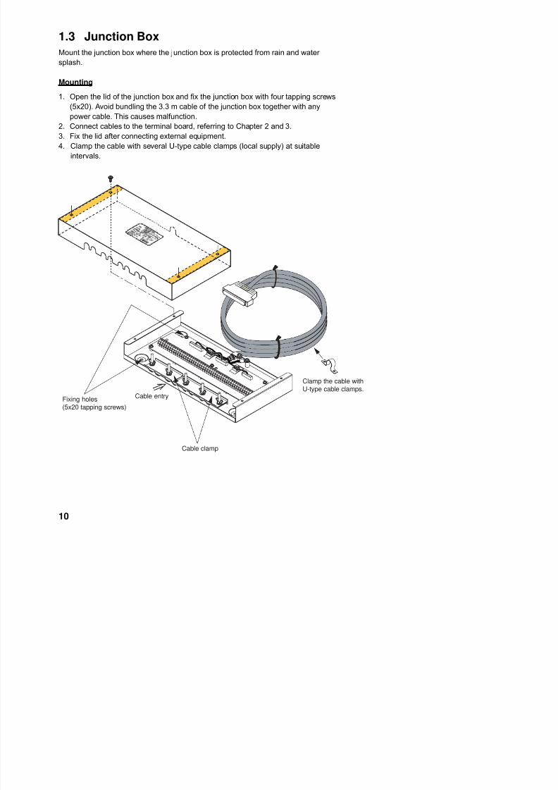
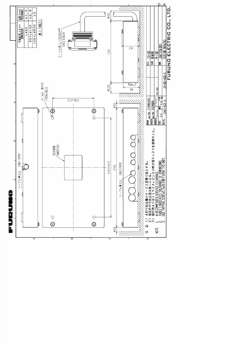
1.3 Junction Box
Mount the junction box where the junction box is protected from rain and water
splash.
Mounting
1. Open the lid of the junction box and fix the junction box with four tapping screws
(5x20). Avoid bundling the 3.3 m cable of the junction box together with any
power cable. This causes malfunction.
2. Connect cables to the terminal board, referring to Chapter 2 and 3.
3. Fix the lid after connecting external equipment.4. Clamp the cable with several U-type cable clamps (local supply) at suitable
intervals.
Clamp the cable withU-type cable clamps.

7/31/2019 FA100 Installation Manual h3 10.25
http://slidepdf.com/reader/full/fa100-installation-manual-h3-1025 17/58
1.4 Power Supply (option)
The length of the power cable between the power supply and the transponder unit
is 3.5 m. Keep this length in mind when selecting a mounting location. A longer
cable should not be used – voltage drop will result, affecting performance.
When selecting a mounting location for the unit, keep the following in mind:
• Keep the unit out away from areas subject to water splash.
• Locate the unit away from exhaust pipes and vents.
• The mounting location should be well ventilated.
• Mount the unit where shock and vibration are minimal.
• A magnetic compass will be affected if the unit is placed too close to it. Observe
the following compass safe distances to prevent disturbance to the magnetic
compass:
Steering compass: 0.6 m
Standard compass: 0.9 m
Fix the unit with four tapping screws (4x16) to a desktop or the deck as shown in
the figure below. It is not necessary to open the cover.
1.5 Pilot Plug (option)The pilot plug should be mounted near where the pilot steers the ship. This plug is
used to connect a PC to display AIS information for use by the pilot. Refer to the
outline drawing at the back of this manual for mounting dimensions.

7/31/2019 FA100 Installation Manual h3 10.25
http://slidepdf.com/reader/full/fa100-installation-manual-h3-1025 18/58
2. WIRING
Connect the equipment, referring to the interconnection diagram at the back this
manual.
AD-10 IN
EXTRA I/O
GPS AntennaGPA-017SGSC-001
PC
AD-100
150M-W2VNEither one
RG-10/UY
RG-10/UY
Attached to Distributor(approx. 1m)
Gyrocompass
LAN cable(category 4 or higher)
TTYCS-1Q**
AIS sentence out(4800 bps)
Distributor unitDB-1
Alarm outGPS receiverHeading sensor
Speed sensor or ROTBeacon receiver
AIS data In/Out
Junction BoxCB-100
ACIN
DCIN
DCOUT
12-24 VDC(C t t th lt ti
Ship's mains100/110/115/200/ 220/230 VAC1φ 50/60 Hz
Power SupplyPR-240-CE
M J - A 3 S P F 0 0 1 3 - 0 3 5 ( 3 . 5 m ) *
TransponderunitFA-100
GPS/VHF ConbinedAntenna GVA-100
8D-FB-CV, 30 m/50 m: OptionRG-10/UY: Local supply
S d d
DPYC-1.5**
LAN
0.6 m
******
***
0.9 m
GPS ANT VHF ANT
Approx. 3.3 m
TTYCS-1Q** or TTYCS-4**24 VDC
: ground is not required.
1.5 sq
AUX-2AUX-1
Pilot Plug

7/31/2019 FA100 Installation Manual h3 10.25
http://slidepdf.com/reader/full/fa100-installation-manual-h3-1025 19/58
ConductorS = 1.5 mmφ = 1.56 mm
2
DPYC-1.5
Armor
Sheath
φ = 11.7 mm
***: Waterproofing connectors
**: DPYC-1.5, TTYCS-1Q and TTYCS-4 are Japan Industry Standard cable.
Use them or the equivalents.
ConductorS = 0.75 mmφ = 1.11 mm
2
TTYCS-1Q (Four core twisted)
Armor
Shield
Sheath
φ = 11.3 mm
ConductorS = 0.75 mmφ = 1.11 mm
2
TTYCS-4 (Four twisted pairs)
Armor
Shield
Sheath
φ = 18.5 mm Sheath
Wrap connector with vulcanizing tape and then vinyl tape. Bind
the tape end with a cable-tie.
Waterproofing connector

7/31/2019 FA100 Installation Manual h3 10.25
http://slidepdf.com/reader/full/fa100-installation-manual-h3-1025 20/58
Cable Connection at Junction Box
Cable fabrication
Armor Sheath Shield
Clamp here by cable clamp.
5 to 6 mm
30
Connection
Procedure
1. Insert driver from direction 1 .
2. Tilt slightly toward 2 .
3. Insert cable core to 3 .
Core 5-6 mm
12
3

7/31/2019 FA100 Installation Manual h3 10.25
http://slidepdf.com/reader/full/fa100-installation-manual-h3-1025 21/58
3. INPUT/OUTPUT SIGNAL
3.1 Inputs from Sensors
There are three input ports (SENSOR 1, 2 and 3) which are based on the IEC
61162-1/2. The protocol is RS422. If there is no HDT signal from a gyrocompass,
connect the gyrocompass signal (Synchro or step signal) to the “AD-10 IN” port
(D-sub 9 pins) of the transponder unit via the FURUNO A/D Converter AD-100 (See
page 16).
1 TD3-A
2 TD3-B
3 GND ISO
4 RD3-A
5 RD3-B
6 GND ISO
7 TD2-A
8 TD2-B
9 GND ISO
10 RD2-A
11 RD2-B
12 GND ISO
13 TD1-A
14 TD1-B
15 GND ISO
16 RD1-A
17 RD1-B
18 GND ISO
TB1 in the junction box
GPS navigator only
TTYCS-1Q
Isolated GND
Heading Signal (HDT)
TTYCS-1Q
Isolated GND
Speed Signal (SOG)
TTYCS-1Q
Isolated GND
SENSOR 3 (EXT GPS IN)
SENSOR 2
SENSOR 1
(4 cores twisted)

7/31/2019 FA100 Installation Manual h3 10.25
http://slidepdf.com/reader/full/fa100-installation-manual-h3-1025 22/58
3.2 Input/Output of AIS Signal
Three input/output ports are provided for RS-422 protocol, based on the IEC
61162-1/2. Data transmission rate is selectable from 4800 bps and 38.4 kbps.
Normally, Radar/ECDIS/PC, etc. are connected to these ports to exchange datawith the AIS. PC standard protocol RS-232C is also provided in the D-sub port of
the transponder unit.
25 TD4-A
26 TD4-B
27 GND ISO
28 RD4-A
29 RD4-B
30 GND ISO31 TD6-A
32 TD6-B
33 GND ISO
34 RD6-A
35 RD6-B
36 GND ISO
37 TD8-A
38 TD8-B
39 GND ISO
40 RD8-A
41 RD8-B
42 GND ISO
43 TD (232C)
44 RD (232C)
TB1 in the junctionbox
L/R (INMARSAT) or
ECDIS/RADAR
TTYCS-4
RD-ATTYCS-4
RD-B
Isolated GND
TD-A
TD-B
Isolated GND
EXTRA I/O
TTYCS-4
PC I/O
RD-A
RD-B
Isolated GND
TD-A
TD-B
Isolated GND
RD-A
RD-B
Isolated GND
TD-A
TD-BIsolated GND
Rx port
Tx port

7/31/2019 FA100 Installation Manual h3 10.25
http://slidepdf.com/reader/full/fa100-installation-manual-h3-1025 23/58
3.3 Input of Gyrocompass Signal
If the gyrocompass has no HDT signal, the AD-10 format (FURUNO format) signal
can be input via the FURUNO A/D Converter AD-100. Connect the AD-100 to the
“AD-10 IN” port (D-sub 9 pin) on the rear panel of the transponder unit.
DATA-H
DATA-L
CLOCK-H
CLOCK-L
GND
F.GND
AD-10 INFA-100
>1>
>2>
>3>
>4>
>8>
>9>
Twisted pair cable (Example: TTYCS-1Q cable)to DATA terminal of AD-100
Note: Set data output interval for 200 ms (instead of 25 ms) by internal jumper
inside the AD-100.
3.4 Alarm Signal Output
The FA-100 generates an alarm signal (relay contact signal) for hardware failure
such as transmitter block or sensor abnormality. For details of alarm type, see the
operator’s manual.
Two kinds of contact signals, on (normal closure) or off (normal open), are output,
and are selected at the junction box CB-100 according to the alarm generator
connected. The maximum current and voltage of the contact are 1 A, 125 VAC and
60 VDC. Normally connect to the NC (normal close) between #45 and #47.
45 AOL
46 AOH
47 AOC
TB-1 in the junction box
#45-#47: Normal Close#46-#47: Normal Open47: common line

7/31/2019 FA100 Installation Manual h3 10.25
http://slidepdf.com/reader/full/fa100-installation-manual-h3-1025 24/58
3.5 LAN Input/Output
The FA-100 supports Ethernet based on LAN. Its protocol is 10BASE-T and the
transmission rate is 10 Mbps. To connect the FA-100 with other equipment (such as
a PC), use a LAN cable category 4 or higher with shield (SDT). Connect it to thePC with an RJ-45 connector, and connect to the FA-100 with a D-sub 9 pin
connector, to avoid noise leakage. To use a commercial LAN cable, remove one
connector and solder a D-sub 9 pin connector, supplied in the installation materials.
TD+
TD-
RD+
RD-
GND
F.GND
LAN (10B-T)FA-100
>1>
>2>
>3>
>4>
>8>
>9>
3 RD+
6 RD-
1 TD+
2 TD-
Twisted pair cable
RJ-45 (Category 4 and higher, SDT)
3.6 Pilot Plug
Use the twisted cable TTYCS-4 between the junction box and the pilot plug. The
cable between the PC and the pilot plug should be prepared by the ship’s pilot.
Junction boxTerminal board
TD A
TD B
RD-A
RD-B
SHIELD
TB1 >1>
>2>
>3>
>4>
>5>
>6>
>7>
J1
37 TD8-A
38 TD8-B39 GND ISO
40 RD8-A
41 RD8-B
42 GND ISO
Pilot plug
TTYCS-4
PC

7/31/2019 FA100 Installation Manual h3 10.25
http://slidepdf.com/reader/full/fa100-installation-manual-h3-1025 25/58
3.7 Jumper Setting in the Junction Box
Each RS-422 RX line (on the PCB 24P0031 in the junction box) has a jumper block
with 240 ohms termination resistor. The junction box is shipped with all jumper
blocks connected between the #3 and #4 terminals pins, terminating RX lines with240 ohms. Assuming that an external equipment has the output voltage of ±5 V,
more than 21 mA of output current is required.
If multiple equipment are connected to an output port of an external equipment,
change to jumper block setting to between the #1 and #2 pins to reduce the load on
the FA-100. Then, the input impedance of the RS-422 RX lines in the FA-100
becomes more than 2.4 k ohms.
We recommend that you leave the connection of the jumper block between #3 and#4 pins if only the FA-100 is connected to an external equipment.
1
2
3
4
Jumper block (6 pcs)
Factory setting: #3-#4

7/31/2019 FA100 Installation Manual h3 10.25
http://slidepdf.com/reader/full/fa100-installation-manual-h3-1025 26/58
3.8 Input/Output Sentences
1) SENSOR 1, SENSOR2, and SENSOR3 ports
These ports can receive IEC61162-1/2 standard data. The transmission rate of sensor 1, 2, and 3 is selectable from 4800 bps and 38.4 kbps through the menu.
Input sentences are as follows:
$xxDTM, $xxGBS, $xxGGA, $xxGLL, $xxGNS, $xxHDT
$xxOSD, $xxRMC, $xxROT, $xxVBW, $xxVTG
Note: The talker of the underlined sentences has priority asfollows:
GN>GP>GL>LC>IN
Other sentences disregard talker.
2) PC I/O, LR or ECDIS/RADAR, EXTRA I/O and EXTRA 1 I/O ports
These ports can receive or output IEC61162-1/2 standard data. The transmissionrate of signals is selectable from 4800 bps and 38.4 kbps through the menu. The
transmission rate of the EXTRA IO port signal is fixed to 4800 bps.
Input sentences are as follows:
$xxABM, $xxACA, $xxACK, $xxAIR
$xxBBM, $xxDTM, $xxGBS, $xxGGA
$xxGLL, $xxGNS, $xxHDT, $xxLRF$xxLRI, $xxOSD, $xxRMC, $xxROT
$xxSSD, $xxVBW, $xxVSD, $xxVTG
Note: The talker of the underlined sentences has priority as
follows:
GN>GP>GL>LC>IN
Other sentences disregard talker.Output sentences are as follows:
$AIABK, $AIACA, $AIALR, $AILRF,
$AILR1, $AILR2, $AILR3, $AITXT,
$AIVDM, $AIVDO

7/31/2019 FA100 Installation Manual h3 10.25
http://slidepdf.com/reader/full/fa100-installation-manual-h3-1025 27/58
3.9 Changing Ship’s Mains Specifications
The power supply PR-240-CE is shipped ready for connection to a 200-230 VAC
ship’s mains. If the ship’s mains is 100 VAC – 115 VAC, change the tap connection
and terminal board connection as below. Attach label supplied as accessories tothe punch mark in the front panel according to the ship’s mains.
Ship’s mains Tap connection Terminal board
connection #1 & #2
100-115 VAC SEL 115 V b
200-230 VAC SEL 230 V a
123 Heat sink
Front
SEL
115 V
SEL
1
2
3
100-115 VAC
1
2
3
200-230 VAC
(a)
(b)
White
Black
White
Black
Punch mark

7/31/2019 FA100 Installation Manual h3 10.25
http://slidepdf.com/reader/full/fa100-installation-manual-h3-1025 28/58
4. SETTING AND ADJUSTMENT
After installing the equipment, set up the own ship’s static information (MMSI, IMOnumber, ship’s name, call sign, type of ship and GPS antenna position). Also, set
up the system settings.
4.1 Setting MMSI, IMO No., Name and Call Sign
1. While holding down the [0] key, press the [POWER] key.
2. After the following message appears, release the [0] key. (It takes severalseconds before the message appears.)
NOW STARTING
CHECKING MEMORY
3. After the following window appears, enter the password. Note that the passwordis known by only the FURUNO dealer.
[ENTER PASSWORD]
PASSWORD:
4. Press the [ENT] key to display the SET MMSI & IMO# window.
Asterisk marks
current selection.
[SET MMSI & IMO#]
MMSI :
IMO# :
NAME :
C.SIGN :
SET: [ENT]

7/31/2019 FA100 Installation Manual h3 10.25
http://slidepdf.com/reader/full/fa100-installation-manual-h3-1025 29/58
9. Enter ship’s name, using up to 20 alphanumeric characters. To switch between
alphabet and numerical character, press the [SFT] key. To enter an alphabet,
press corresponding key several times until desired letter is displayed. For
example, if you press the [2] key continuously, the character A, B and C appear
cyclically. If you want to enter the same letter or an other letter with the samekey (for example, AA or AC), press the [6] key while pressing the [SFT] key, to
send the cursor to the next position.
10. Press the [NEXT] key to select C.SIGN.
11. Enter call sign, using up to seven alphanumeric characters.
12. Press the [ENT] key to register data. The INIT SETTINGS sub-menu appears.

7/31/2019 FA100 Installation Manual h3 10.25
http://slidepdf.com/reader/full/fa100-installation-manual-h3-1025 30/58
4.2 Setting GPS Antenna Position andShip’s Type
1. In the INIT SETTING sub-menu, press the [6] key to open the SET ANTENNA
POS window.
SET ANTENNA POS
1 INTERNAL ANT POS
2 EXTERNAL ANT POS
SET ANTENNA POS window
2. With 1 selected, press the [ENT] key. The 1 is for entering internal GPS antenna
position and 2 is for external GPS which is connected to the AIS.
[INTERNAL ANT POS]
A: 000 m
B: 000 mC: 00 m
D: 00 m
A
B
C D
INTERNAL ANT POS window
3. Enter locations of GPS antenna, by using the numeric keys and the [NEXT] key,
and finally press the [ENT] key. A: Distance from bow to GPS antenna position
B: Distance from stern to GPS antenna position
C: Distance from port to GPS antenna position
D: Distance from starboard to GPS antenna position
4. Enter external GPS antenna position similar to how you entered internal GPS
antenna position.
5. Press the [MENU] key to return to the INIT SETTINGS sub-menu.6. Press the [4] key to display the SET TYPE&CREW window.
[SET TYPE&CREW]
CREW : 0012
TYPE CLASS : A TYPE CLASS cannot

7/31/2019 FA100 Installation Manual h3 10.25
http://slidepdf.com/reader/full/fa100-installation-manual-h3-1025 31/58
7. Press the [NEXT] key to select TYPE NO.
Confirm type of ship with ship’s captain before setting it.
8. Press the [2], [4], [6] or [8] key as appropriate to select your ship’s type,
referring to the list on below.
10 FUTURE USE ALL SHIPS OF THIS TYPE 60 PASSENGER SHIPS ALL SHIPS OF THIS TYPE
11 FUTURE USE CARRYING DG, HS, OR MP(A) 61 PASSENGER SHIPS CARRYING DG, HS, OR MP(A)
12 FUTURE USE CARRYING DG, HS, OR MP(B) 62 PASSENGER SHIPS CARRYING DG, HS, OR MP(B)
13 FUTURE USE CARRYING DG, HS, OR MP(C) 63 PASSENGER SHIPS CARRYING DG, HS, OR MP(C)
14 FUTURE USE CARRYING DG, HS, OR MP(D) 64 PASSENGER SHIPS CARRYING DG, HS, OR MP(D)
15 FUTURE USE FUTURE USE 65 PASSENGER SHIPS FUTURE USE
16 FUTURE USE FUTURE USE 66 PASSENGER SHIPS FUTURE USE
17 FUTURE USE FUTURE USE 67 PASSENGER SHIPS FUTURE USE
18 FUTURE USE FUTURE USE 68 PASSENGER SHIPS FUTURE USE
19 FUTURE USE NONE 69 PASSENGER SHIPS NONE20 WIG ALL SHIPS OF THIS TYPE 70 CARGO SHIPS ALL SHIPS OF THIS TYPE
21 WIG CARRYING DG, HS, OR MP(A) 71 CARGO SHIPS CARRYING DG, HS, OR MP(A)
22 WIG CARRYING DG, HS, OR MP(B) 72 CARGO SHIPS CARRYING DG, HS, OR MP(B)
23 WIG CARRYING DG, HS, OR MP(C) 73 CARGO SHIPS CARRYING DG, HS, OR MP(C)
24 WIG CARRYING DG, HS, OR MP(D) 74 CARGO SHIPS CARRYING DG, HS, OR MP(D)
25 WIG FUTURE USE 75 CARGO SHIPS FUTURE USE
26 WIG FUTURE USE 76 CARGO SHIPS FUTURE USE
27 WIG FUTURE USE 77 CARGO SHIPS FUTURE USE
28 WIG FUTURE USE 78 CARGO SHIPS FUTURE USE
29 WIG NONE 79 CARGO SHIPS NONE
30 FISHING 80 TANKER ALL SHIPS OF THIS TYPE31 TOWING 81 TANKER CARRYING DG, HS, OR MP(A)
32 LENGTH OF THE TOW EXCEEDS 200M OR BREADTH EXCEEDS 25M 82 TANKER CARRYING DG, HS, OR MP(B)
33 ENGAGED IN DREDGING OR UNDERWATER OPERATIONS 83 TANKER CARRYING DG, HS, OR MP(C)
34 ENGAGED IN DIVING OPEARATIONS 84 TANKER CARRYING DG, HS, OR MP(D)
35 ENGAGED IN MILITARY OPEARATIONS 85 TANKER FUTURE USE
36 SAILING 86 TANKER FUTURE USE
37 PLEASURE CRAFT 87 TANKER FUTURE USE
38 FUTURE USE 88 TANKER FUTURE USE
39 FUTURE USE 89 TANKER NONE
40 HSC ALL SHIPS OF THIS TYPE 90 OTHER TYPE OF SHI ALL SHIPS OF THIS TYPE41 HSC CARRYING DG, HS, OR MP(A) 91 OTHER TYPE OF SHI CARRYING DG, HS, OR MP(A)
42 HSC CARRYING DG, HS, OR MP(B) 92 OTHER TYPE OF SHI CARRYING DG, HS, OR MP(B)
43 HSC CARRYING DG, HS, OR MP(C) 93 OTHER TYPE OF SHI CARRYING DG, HS, OR MP(C)
44 HSC CARRYING DG, HS, OR MP(D) 94 OTHER TYPE OF SHI CARRYING DG, HS, OR MP(D)
45 HSC FUTURE USE 95 OTHER TYPE OF SHI FUTURE USE
46 HSC FUTURE USE 96 OTHER TYPE OF SHI FUTURE USE
47 HSC FUTURE USE 97 OTHER TYPE OF SHI FUTURE USE
48 HSC FUTURE USE 98 OTHER TYPE OF SHI FUTURE USE
49 HSC NONE 99 OTHER TYPE OF SHI NONE
50 PILOT
51 SEACH AND RESCURE VESSELS
52 TUGS
53 PORT TENDERS
54 VESSELS WITH ANTI-POLUUTION FACILITIES OR EQUIPMENT
55 LAW ENFOREMENT VESSELS
56 SPARE-FOR ASSIGNMENTS TO LOCAL VESSELS
57 SPARE FOR ASSIGNMENTS TO LOCAL VESSELS
WIG: Wing in groundHSC: High speed craft
DG: Dangerous goods
HS: Harmful substances
MP: Marine pollutants
0-9: Undefined

7/31/2019 FA100 Installation Manual h3 10.25
http://slidepdf.com/reader/full/fa100-installation-manual-h3-1025 32/58
10. Press the [MENU] key. The SAVE confirmation window appears.
SAVE ?
YES
NO
CANCEL
SAVE confirmation window
11. With YES selected, press the [ENT] key to save the data.
4.3 System Settings1. Press the [MENU] key to open the main menu.
2. Press the [6] key to open the SYSTEM SETTINGS sub-menu.
[SYSTEM SETTINGS]
1 SET I/O PORT
2 SET CHANNEL
3 SET LR MODE
4 SET OTHER I/O
5 SET BUZZER
SYSTEM SETTINGS sub-menu
3. Press the [1] key to display the SET I/O PORT sub-menu.
[SET I/O PORT]
1 I/O SPEED
2 I/O FUNCTION
3 I/O PRIORITY
4 SET LAN (IP ADDR)
SET I/O PORT sub-menu
4. Press the [1] key to display the I/O SPEED window.

7/31/2019 FA100 Installation Manual h3 10.25
http://slidepdf.com/reader/full/fa100-installation-manual-h3-1025 33/58
5. Select the appropriate data transmission rate from 4800 bps and 38.4 kbps for
PC I/O, SNSR 1, SNSR 2, SNSR 3, LR, BCON (beacon receiver), EXTRA1 and
EXTRA2, by pressing the [SFT] key. To select each item, press the [NEXT] key.
To go backward, press the [NEXT] key while pressing the [SFT] key.
6. Press the [ENT] key to return to the SET I/O PORT sub-menu.7. Press the [2] key to display the I/O FUCTION window.
[I/O FUNCTION]
PORT LR: EXT DISP +-
I/O FUNCTION window
8. Press the [SFT+/-] key to select EXT DISP or LR, depending on equipment
connected.EXT DISP: External display, such as radar, ECDIS
LR: Long range communication, such INMARSAT communication equipment
9. Press the [ENT] key to return to the SET I/O PORT sub-menu.
10. Press the [3] key to display the I/O PRIORITY window.
[I/O PRIORITY]
1 L/L COG SOG2 HDG
3 ROT
4 AIS
I/O PRIORITY window
11. Press the [1] key to display the L/L COG SOG window.
SN2: 2
[L/L COG SOG]
SN1: 1

7/31/2019 FA100 Installation Manual h3 10.25
http://slidepdf.com/reader/full/fa100-installation-manual-h3-1025 34/58
12. Set L/L position, COG and SOG data priority with the numeric keys according to
sensors connected.
COG: Course over ground
SOG: Speed over ground
13. Press the [ENT] key to return to the I/O PRIORITY window.
Note: If you have entered 8, 9 or the same value for more than one item at step
12, the following error message appears. In this case, press the [ENT]
key and set the priority correctly.
[ERROR]
CAN NOT INPUTSAME VALUE !
ESC: [ENT]
[ERROR]
OUT OF RANGE !PRIORITY: 1-7
ESC: [ENT]
ERROR message
14. Set the priority for HDG and ROT similar to how you did for “L/L COG SOG”.
The priority of heading data entered from the AD-10 IN port is the lowest.
15. To set the priority of AIS, press the [4] key to choose AIS.
[AIS]
RESPONSE:PC
- - - - - - - - - - - - - - - - - - - -
EX1: ENBL
LR : ENBL
PC : ENBL
LAN: ENBL
+-
+-
+-
+-+
-DEFAULT: [CLR]
AIS PRIORITY setting window
16. With RESPONSE selected, press the [SFT] key to select PC, NONE, LAN, EX1
or LR as appropriate.
Set an output port for response from other party after you transmit messages or
interrogation from the PC, ECDIS, LR, or LAN.
NONE : No output for response
PC : Output to PC I/O port
LAN : Output to LAN port
LR : Output to LR or ECDIS/RADAR port
20 P [4] k t di l th SET LAN (IP ADRS) i d
7/31/2019 FA100 Installation Manual h3 10.25
http://slidepdf.com/reader/full/fa100-installation-manual-h3-1025 35/58
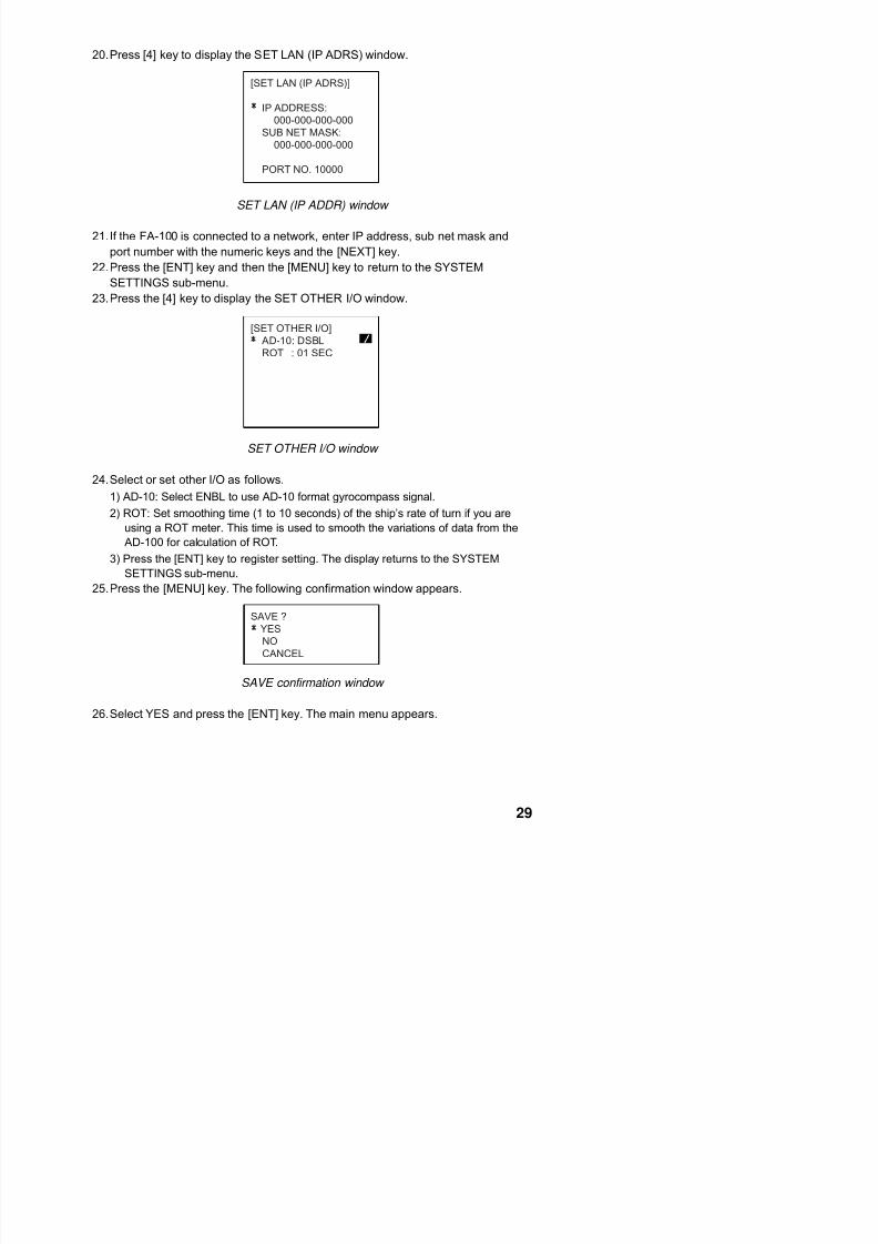
20. Press [4] key to display the SET LAN (IP ADRS) window.
[SET LAN (IP ADRS)]
IP ADDRESS:
000-000-000-000SUB NET MASK:
000-000-000-000
PORT NO. 10000
SET LAN (IP ADDR) window
21. If the FA-100 is connected to a network, enter IP address, sub net mask and
port number with the numeric keys and the [NEXT] key.
22. Press the [ENT] key and then the [MENU] key to return to the SYSTEM
SETTINGS sub-menu.
23. Press the [4] key to display the SET OTHER I/O window.
[SET OTHER I/O]AD-10: DSBL
ROT : 01 SEC
+-
SET OTHER I/O window
24. Select or set other I/O as follows.
1) AD-10: Select ENBL to use AD-10 format gyrocompass signal.
2) ROT: Set smoothing time (1 to 10 seconds) of the ship’s rate of turn if you are
using a ROT meter. This time is used to smooth the variations of data from the
AD-100 for calculation of ROT.
3) Press the [ENT] key to register setting. The display returns to the SYSTEM
SETTINGS sub-menu.
25. Press the [MENU] key. The following confirmation window appears.
SAVE ?

7/31/2019 FA100 Installation Manual h3 10.25
http://slidepdf.com/reader/full/fa100-installation-manual-h3-1025 36/58
This page is intentionally left blank.
A-1

7/31/2019 FA100 Installation Manual h3 10.25
http://slidepdf.com/reader/full/fa100-installation-manual-h3-1025 37/58
A-2

7/31/2019 FA100 Installation Manual h3 10.25
http://slidepdf.com/reader/full/fa100-installation-manual-h3-1025 38/58
A-3

7/31/2019 FA100 Installation Manual h3 10.25
http://slidepdf.com/reader/full/fa100-installation-manual-h3-1025 39/58

7/31/2019 FA100 Installation Manual h3 10.25
http://slidepdf.com/reader/full/fa100-installation-manual-h3-1025 40/58
A-4
A 5

7/31/2019 FA100 Installation Manual h3 10.25
http://slidepdf.com/reader/full/fa100-installation-manual-h3-1025 41/58
PACKING LISTPACKING LISTPACKING LISTPACKING LIST 24AA-X-9852 -5
PR-240-CEPR-240-CEPR-240-CEPR-240-CE
N A M E O U T L I N E DESCRIPTION/CODE № Q'TY
1/1
ユニットユニットユニットユニット UNITUNITUNITUNIT
AC-DC電源
POWER SUPPLY UNIT
PR-240-CE
000-053-879
1
工事材料工事材料工事材料工事材料 INSTALLATION MATERIALSINSTALLATION MATERIALSINSTALLATION MATERIALSINSTALLATION MATERIALS CP24-00151CP24-00151CP24-00151CP24-00151
PR-240-CE電源変更手順書
POWER MODIFICATION PROCEDURES
C52-00205-A
000-147-013
1
デンゲンハリマーク
POWER LABEL
24-003-4101-3
100-299-773
1
+トラスタッピンネジ
+TAPPING SCREW
4X16 SUS304 1シュ
000-802-080
4
A-5
A 6

7/31/2019 FA100 Installation Manual h3 10.25
http://slidepdf.com/reader/full/fa100-installation-manual-h3-1025 42/58
A-6

7/31/2019 FA100 Installation Manual h3 10.25
http://slidepdf.com/reader/full/fa100-installation-manual-h3-1025 43/58
A-7

7/31/2019 FA100 Installation Manual h3 10.25
http://slidepdf.com/reader/full/fa100-installation-manual-h3-1025 44/58
A-8

7/31/2019 FA100 Installation Manual h3 10.25
http://slidepdf.com/reader/full/fa100-installation-manual-h3-1025 45/58
D - 2

7/31/2019 FA100 Installation Manual h3 10.25
http://slidepdf.com/reader/full/fa100-installation-manual-h3-1025 46/58
O c t . 2 1 , ' 0
2
D - 3

7/31/2019 FA100 Installation Manual h3 10.25
http://slidepdf.com/reader/full/fa100-installation-manual-h3-1025 47/58
O c t . 2 1 , ' 0
2

7/31/2019 FA100 Installation Manual h3 10.25
http://slidepdf.com/reader/full/fa100-installation-manual-h3-1025 48/58
D-4a

7/31/2019 FA100 Installation Manual h3 10.25
http://slidepdf.com/reader/full/fa100-installation-manual-h3-1025 49/58
D-5

7/31/2019 FA100 Installation Manual h3 10.25
http://slidepdf.com/reader/full/fa100-installation-manual-h3-1025 50/58
D - 6
7/31/2019 FA100 Installation Manual h3 10.25
http://slidepdf.com/reader/full/fa100-installation-manual-h3-1025 51/58
J a n .
9 , ' 0
3
D - 7
7/31/2019 FA100 Installation Manual h3 10.25
http://slidepdf.com/reader/full/fa100-installation-manual-h3-1025 52/58
J a n .
9 ,
' 0 3
D-8

7/31/2019 FA100 Installation Manual h3 10.25
http://slidepdf.com/reader/full/fa100-installation-manual-h3-1025 53/58
D-9

7/31/2019 FA100 Installation Manual h3 10.25
http://slidepdf.com/reader/full/fa100-installation-manual-h3-1025 54/58
D-10

7/31/2019 FA100 Installation Manual h3 10.25
http://slidepdf.com/reader/full/fa100-installation-manual-h3-1025 55/58
D-11

7/31/2019 FA100 Installation Manual h3 10.25
http://slidepdf.com/reader/full/fa100-installation-manual-h3-1025 56/58

7/31/2019 FA100 Installation Manual h3 10.25
http://slidepdf.com/reader/full/fa100-installation-manual-h3-1025 57/58

7/31/2019 FA100 Installation Manual h3 10.25
http://slidepdf.com/reader/full/fa100-installation-manual-h3-1025 58/58


