Page 1
FACULTAD DE ESTUDIOS SUPERIORES CUAUTITLÁN
DEPARTAMENTO DE INGENIERÍA
LABORATORIO DE TECNOLOGÍA DE MATERIALES
LECTURAS DE INGENIERÍA 18
FATIGUE, AN FATIGUE, AN FATIGUE, AN FATIGUE, AN OVERVIEW OVERVIEW OVERVIEW OVERVIEW
RECOPILÓ:
M. en I. Felipe Díaz del Castillo Rodríguez.
CUAUTITLÁN IZCALLI 2011
Page 2
UNAM FES-CUAUTITLÁN
DEPARTAMENTO DE INGENIERÍA Mtro. FELIPE DÍAZ DEL CASTILLO R.
- 1 -
Fatigue has become progressively more prevalent as technology has developed a greater amount
of equipment, such as automobiles, aircraft, compressors, pumps, turbines, etc., subject to
repeated loading and vibration. Today it is often stated that fatigue accounts for al least 90
percent of all service failures due to mechanical causes.
1.1. In the begining
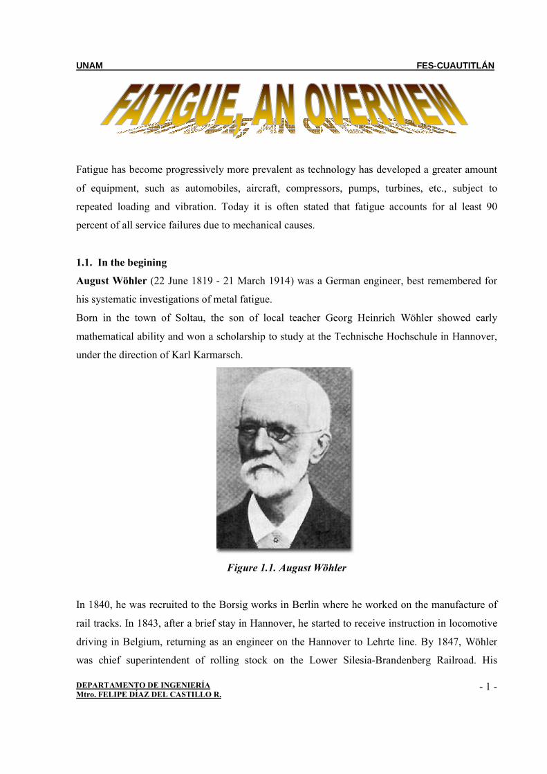
August Wöhler (22 June 1819 - 21 March 1914) was a German engineer, best remembered for
his systematic investigations of metal fatigue.
Born in the town of Soltau, the son of local teacher Georg Heinrich Wöhler showed early
mathematical ability and won a scholarship to study at the Technische Hochschule in Hannover,
under the direction of Karl Karmarsch.
Figure 1.1. August Wöhler
In 1840, he was recruited to the Borsig works in Berlin where he worked on the manufacture of
rail tracks. In 1843, after a brief stay in Hannover, he started to receive instruction in locomotive
driving in Belgium, returning as an engineer on the Hannover to Lehrte line. By 1847, Wöhler
was chief superintendent of rolling stock on the Lower Silesia-Brandenberg Railroad. His
Page 3
UNAM FES-CUAUTITLÁN
DEPARTAMENTO DE INGENIERÍA Mtro. FELIPE DÍAZ DEL CASTILLO R.
- 2 -
growing reputation led to his appointment in 1852 by the Prussian minister of commerce to
investigate the causes of fracture in railroad axles, work that was to occupy Wöhler over the next
two decades.
The railroad was nationalised in 1854 and the recognition of his keen administration and
technical leadership resulted in his appointment as director of the newly formed Imperial
Railways, based at the board's headquarters in Strasbourg, a post he held until his retirement in
1889.
Wöhler started his axle investigations by research into the theory of elasticity and was led, in
1855, to a method for predicting the deflection of lattice beams that anticipated the work of Émile
Clapeyron. He also introduced the practice of supporting one end of a bridge on roller bearings to
allow for thermal expansion.
His work on fatigue marks the first systematic investigation of σ-N Curves, also known as
Wöhler curves, to characterise the fatigue behaviour of materials. Such curves can be used to
minimise the problem of fatigue by lowering the stress at critical points in a component. Wohler
showed clearly that fatigue occurs by crack growth from surface defects until the product can no
longer support the applied load. The history of a fracture can be understood from a study of the
fracture surface. He developed apparatus for repeated loading of railway axles, mainly because
many accidents were caused by sudden fatigue fracture. The presentation of his work at the Paris
Exposition in 1867 brought it to a wide international audience.
Wöhler was an advocate of state standardisation, testing and certification of iron and steel.
He died in Hannover in 1914.
Page 4
UNAM FES-CUAUTITLÁN
DEPARTAMENTO DE INGENIERÍA Mtro. FELIPE DÍAZ DEL CASTILLO R.
- 3 -
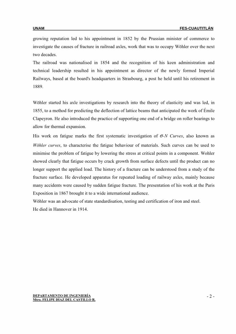
Figure 1.2. Publication of Wöhler's fatigue experience, 1871
1.2. Introduction
Components of machines, vehicles, and structures are frequently subjected to repeated loads, also
called cyclic loads and the resulting cyclic stresses can lead to microscopic physical damage to
the materials involved. Even at stresses well below a given material’s ultimate strength, this
microscopic damage can accumulate with continued cycling until it develops into a crack or other
macroscopic damage that leads to failure of the component.
The process of damage and failure due to cyclic loading is called fatigue. Use of this term arose
because it appeared to early investigators that cyclic stresses caused a gradual but not readily
observable change in the ability of the material to resist stress.
It has been recognized since 1830 that a metal subjected to a repetitive or fluctuating stress will
fail at a stress much lower than that required to cause fracture on a single application of load.
Failures occurring under conditions of dynamic loading are called fatigue failures, presumably
because it is generally observed that these failures occur only after a considerable period of
service.
Page 5
UNAM FES-CUAUTITLÁN
DEPARTAMENTO DE INGENIERÍA Mtro. FELIPE DÍAZ DEL CASTILLO R.
- 4 -
Fatigue has become progressively more prevalent as technology has developed a greater amount
of equipment, such as automobiles, aircraft, compressors, pumps, turbines, etc., subject to
repeated loading and vibration. Today it is often stated that fatigue accounts for al least 90
percent of all service failures due to mechanical causes.
A fatigue failure is particularly insidious because it occurs without any obvious warning. Fatigue
results in a brittle-appearing fracture, with no gross deformation at the fracture. On a macroscopic
scale the fracture surface is usually normal to the direction of the principal tensile stress.
A fatigue failure can usually be recognized from the appearance of the fracture surface, which
shows a smooth region, due to the rubbing action as the crack propagated through the section,
and a rough region, where the member has failed in a ductile manner when the cross section was
no longer able to carry the load. Frequently the progress of the fracture is indicated by a series of
rings, or "beach marks", progressing inward from the point of initiation of the failure.
Three basic factors are necessary to cause fatigue failure. These are:
• Maximum tensile stress of sufficiently high value,
• Large enough variation or fluctuation in the applied stress, and
• Sufficiently large number of cycles of the applied stress.
In addition, there are a host of other variables, such as stress concentration, corrosion,
temperature, overload, metallurgical structure, residual stresses, and combined stresses, which
tend to alter the conditions for fatigue. Since we have not yet gained a complete understanding of
what causes fatigue in metals, it will be necessary to discuss each of these factors from an
essentially empirical standpoint,
standpoint.
1.3. Stress Cycles
At the outset it will be advantageous to define briefly the general types of fluctuating stresses
which can cause fatigue. Figure 1 serves to illustrate typical fatigue stress cycles.
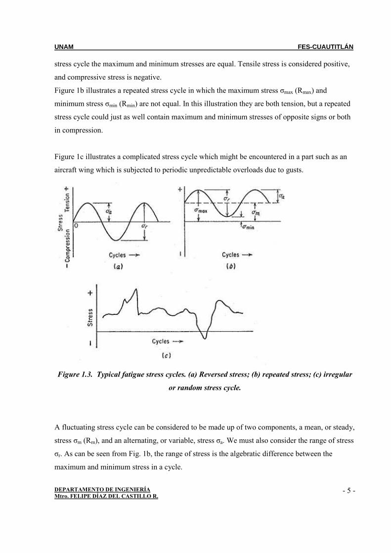
Figure 1a illustrates a completely reversed cycle of stress of sinusoidal form. For this type of
Page 6
UNAM FES-CUAUTITLÁN
DEPARTAMENTO DE INGENIERÍA Mtro. FELIPE DÍAZ DEL CASTILLO R.
- 5 -
stress cycle the maximum and minimum stresses are equal. Tensile stress is considered positive,
and compressive stress is negative.
Figure 1b illustrates a repeated stress cycle in which the maximum stress σmax (Rmax) and
minimum stress σmin (Rmin) are not equal. In this illustration they are both tension, but a repeated
stress cycle could just as well contain maximum and minimum stresses of opposite signs or both
in compression.
Figure 1c illustrates a complicated stress cycle which might be encountered in a part such as an
aircraft wing which is subjected to periodic unpredictable overloads due to gusts.
Figure 1.3. Typical fatigue stress cycles. (a) Reversed stress; (b) repeated stress; (c) irregular
or random stress cycle.
A fluctuating stress cycle can be considered to be made up of two components, a mean, or steady,
stress σm (Rm), and an alternating, or variable, stress σa. We must also consider the range of stress
σr. As can be seen from Fig. 1b, the range of stress is the algebratic difference between the
maximum and minimum stress in a cycle.
Page 7
UNAM FES-CUAUTITLÁN
DEPARTAMENTO DE INGENIERÍA Mtro. FELIPE DÍAZ DEL CASTILLO R.
- 6 -
1.4. The S-N Curve
The basic method of presenting engineering fatigue data is by means of the S-N curve, a plot of
stress S against the number of cycles to failure N. A log scale is almost always used for N. The
value of stress that is plotted can be σa, σmax, or σmin. The stress values are usually nominal
stresses, i.e., there is no adjustment for stress concentration. The S-N relationship is determined
for a specified value of σm, R (R=σmin/σmax), or A (A=σa/σm).
Most determinations of the fatigue properties of materials have been made in completed reversed
bending, where the mean stress is zero.
It will be noted that this S-N curve is concerned chiefly with fatigue failure at high numbers of
cycles (N > 105 cycles). Under these conditions the stress, on a gross scale, is elastic, but as we
shall see shortly the metal deforms plastically in a highly localized way. At higher stresses the
fatigue life is progressively decreased, but the gross plastic deformation makes interpretation
difficult in terms of stress.
For the low-cycle fatigue region (N < 104 or 105 cycles) tests are conducted with controlled
cycles of elastic plus plastic strain instead of controlled load or stress cycles.
The usual procedure for determining an S-N curve is to test the first specimen at a high stress
where failure is expected in a fairly short number of cycles, e.g., at about two-thirds the static
tensile strength of the material. The test stress is decreased for each succeeding specimen until
one or two specimens do not fail in the specified numbers of cycles, which is usually at least 107
cycles.
The highest stress at which a runout (non-failure) is obtained is taken as the fatigue limit. For
materials without a fatigue limit the test is usually terminated for practical considerations at a low
stress where the life is about 108 or 5x10⁸ cycles. The S-N curve is usually determined with about
8 to 12 specimens.
Page 8
UNAM FES-CUAUTITLÁN
DEPARTAMENTO DE INGENIERÍA Mtro. FELIPE DÍAZ DEL CASTILLO R.
- 7 -
1.5. Fatigue test
The definition of fatigue testing can be thought of as simply applying cyclic loading to your test
specimen to understand how it will perform under similar conditions in actual use. The load
application can either be a repeated application of a fixed load or simulation of in-service loads.
The load application may be repeated millions of times and up to several hundred times per
second.
1.5.1. Why Do a Fatigue Test?
In many applications, materials are subjected to vibrating or oscillating forces. The behavior of
materials under such load conditions differs from the behavior under a static load. Because the
material is subjected to repeated load cycles (fatigue) in actual use, designers are faced with
predicting fatigue life, which is defined as the total number of cycles to failure under specified
loading conditions. Fatigue testing gives much better data to predict the in-service life of
materials.
1.6. Statistical Nature of Fatigue
A considerable amount of interest has been shown in the statistical analysis of fatigue data and in
reasons for the variability in fatigue-test results. Since fatigue life and fatigue limit are statistical
quantities, it must be realized that considerable deviation from an average curve determined with
only a few specimens is to be expected.
It is necessary to think in terms of the probability of a specimen attaining a certain life at a given
stress or the probability of failure at a given stress in the vicinity of the fatigue limit. To do this
requires the testing of considerably more specimens than in the past so that the statistical
parameters for estimating these probabilities can be determined.
The basic method for expressing fatigue data should then be a three-dimensional surface
representing the relationship between stress, number of cycles to failure, and probability of
failure.
In determining the fatigue limit of a material, it should be recognized that each specimen has its
own fatigue limit, a stress above which it will fail but below which it will not fail, and that this
Page 9
UNAM FES-CUAUTITLÁN
DEPARTAMENTO DE INGENIERÍA Mtro. FELIPE DÍAZ DEL CASTILLO R.
- 8 -
critical stress varies from specimen to specimen for very obscure reasons. It is known that
inclusions in steel have an important effect on the fatigue limit and its variability, but even
vacuum-melted steel shows appreciable scatter in fatigue limit.
The statistical problem of accurately determining the fatigue limit is complicated by the fact that
we cannot measure the individual value of the fatigue limit for any given specimen. We can only
test a specimen at a particular stress, and if the specimen fails, then the stress was somewhere
above the fatigue limit of the specimen. The two statistical methods which are used for making a
statistical estimate of the fatigue limit are called probit analysis and the staircase method. The
procedures for applying these methods of analysis to the determination of the fatigue limit have
been well established
1.7. Effect of Mean Stress on Fatigue
Much of the fatigue data in the literature have been determined for conditions of completely
reversed cycles of stress, σm = 0. However, conditions are frequently met in engineering practice
where the stress situation consists of an alternating stress and a superimposed mean, or steady,
stress. There are several possible methods of determining an S-N diagram for a situation where
the mean stress is not equal to zero.
Cyclic Stress-Strain Curve
Cyclic strain controlled fatigue, as opposed to our previous discussion of cyclic stress controlled
fatigue, occurs when the strain amplitude is held constant during cycling. Strain controlled cyclic
loading is found in thermal cycling, where a component expands and contracts in response to
fluctuations in the operating temperature.
In a more general view, the localized plastic strains at a notch subjected to either cyclic stress or
strain conditions result in strain controlled conditions near the root of the notch due to the
constraint effect of the larger surrounding mass of essentially elastically deformed material.
Since plastic deformation is not completely reversible, modifications to the structure occur during
cyclic straining and these can result in changes in the stress-strain response. Depending on the
initial state a metal may undergo cyclic hardening, cyclic softening, or remain cyclically stable. It
Page 10
UNAM FES-CUAUTITLÁN
DEPARTAMENTO DE INGENIERÍA Mtro. FELIPE DÍAZ DEL CASTILLO R.
- 9 -
is not uncommon for all three behaviors to occur in a given material depending on the initial state
of the material and the test conditions.
Generally the hysteresis loop stabilizes after about 100 cycles and the material arrives at an
equilibrium condition for the imposed strain amplitude. The cyclically stabilized stress-strain
curve may be quite different from the stress-strain curve obtained on monotonic static loading.
The cyclic stress-strain curve is usually determined by connecting the tips of stable hysteresis
loops from constant-strain-amplitude fatigue tests of specimens cycled at different strain
amplitudes. Under conditions where saturation of the hysteresis loop is not obtained, the
maximum stress amplitude for hardening or the minimum stress amplitude for softening is used.
Sometimes the stress is taken at 50 percent of the life to failure. Several shortcut procedures have
been developed.
1.8. Low-Cycle Fatigue
Although historically fatigue studies have been concerned with conditions of service in which
failure occurred at more than 104 cycles of stress, there is growing recognition of engineering
failures which occur at relatively high stress and low numbers of cycles to failure. This type of
fatigue failure must be considered in the design of nuclear pressure vessels, steam turbines, and
most other types of power machinery.
Low-cycle fatigue conditions frequently are created where the repeated stresses are of thermal
origin. Since thermal stresses arise from the thermal expansion of the material, it is easy to see
that in this case fatigue results from cyclic strain rather than from cyclic stress.
1.9. Structural Features of Fatigue
Studies of the basic structural changes that occur when a metal is subjected to cyclic stress have
found it convenient to divide the fatigue process into the following stages:
• Crack initiation includes the early development of fatigue damage which can be
removed by a suitable thermal anneal.
• Slip-band crack growth involves the deepening of the initial crack on planes of high
shear stress. This frequently is called stage I crack growth.
Page 11
UNAM FES-CUAUTITLÁN
DEPARTAMENTO DE INGENIERÍA Mtro. FELIPE DÍAZ DEL CASTILLO R.
- 10 -
• Crack growth on planes of high tensile stress involves growth of well-defined crack in
direction normal to maximum tensile stress. Usually called stage II crack growth.
• Ultimate ductile failure occurs when the crack reaches sufficient length so that the
remaining cross section cannot support the applied load.
The relative proportion of the total cycles to failure that are involved with each stage depends on
the test conditions and the material. However, it is well established that a fatigue crack can be
formed before 10 percent of the total life of the specimen has elapsed. There is, of course,
considerable ambiguity in deciding when a deepened slip band should be called a crack.
In general, larger proportions of the total cycles to failure are involved with the propagation of
stage II cracks in low-cycle fatigue than in long-life fatigue, while stage I crack growth comprises
the largest segment for low-stress, high-cycle fatigue. If the tensile stress is high, as in the fatigue
of sharply notched specimens, stage I crack growth may not be observed at all.
An overpowering structural consideration in fatigue is the fact that fatigue cracks usually are
initiated at a free surface. In those rare instances where fatigue cracks initiate in the interior there
is always an interface involved, such as the interface of a carburized surface layer and the base
metal.
Fatigue has certain things in common with plastic flow and fracture under static or unidirectional
deformation. The work of Gough has shown that a metal deforms under cyclic strain by slip on
the same atomic planes and in the same crystallographic directions as in unidirectional strain.
Whereas with unidirectional deformation slip is usually widespread throughout all the grains, in
fatigue some grains will show slip lines while other grains will give no evidence of slip.
Slip lines are generally formed during the first few thousand cycles of stress. Successive cycles
produce additional slip bands, but the number of slip bands is not directly proportional to the
number of cycles of stress. In many metals the increase in visible slip soon reaches a saturation
value, which is observed as distorted regions of heavy slip. Cracks are usually found to occur in
the regions of heavy deformation parallel to what was originally a slip band. Slip bands have
been observed at stresses below the fatigue limit of ferrous materials. Therefore, the occurrence
of slip during fatigue does not in itself mean that a crack will form.
A study of crack formation in fatigue can be facilitated by interrupting the fatigue test to remove
the deformed surface by electro polishing. There will generally be several slip bands which are
Page 12
UNAM FES-CUAUTITLÁN
DEPARTAMENTO DE INGENIERÍA Mtro. FELIPE DÍAZ DEL CASTILLO R.
- 11 -
more persistent than the rest and which will remain visible when the other slip lines have been
polished away. Such slip bands have been observed after only 5 percent of the total life of the
specimen. These persistent slip bands are embryonic fatigue cracks, since they open into wide
cracks on the application of small tensile strains. Once formed, fatigue cracks tend to propagate
initially along slip planes, although they later take a direction normal to the maximum applied
tensile stress. Fatigue-crack propagation is ordinarily transgranular.
An important structural feature, which appears to be unique to fatigue deformation, is the
formation on the surface of ridges and grooves called slip-band extrusions and slip-band
intrusions. Extremely careful metallography on tapered sections through the surface of the
specimen has shown that fatigue cracks initiate at intrusions and extrusions.
W. A. Wood, who made many basic contributions to the understanding of the mechanism of
fatigue, suggested a mechanism for producing slip-band extrusions and intrusions. He interpreted
microscopic observations of slip produced by fatigue as indicating that the slip bands are the
result of a systematic buildup of fine slip movements, corresponding to movements of the order
of 10-7cm rather than steps of 10-5 to 10-4 cm, which are observed for static slip hands.
Such a mechanism is believed to allow for the accommodation of the large total strain
(summation of the micro strain in each cycle) without causing appreciable strain hardening. The
notch would be a stress raiser with a notch root of atomic dimensions. Such a situation might well
be the start of a fatigue crack. This mechanism for the initiation of a fatigue crack is in agreement
with the facts that fatigue cracks start at surfaces and that cracks have been found lo initiate at
slip-band intrusions and extrusions.
Extensive structural studies of dislocation arrangements in persistent slip bands have brought
much basic understanding to the fatigue fracture process.
The stage I crack propagates initially along the persistent slip bands. In a polycrystalline metal
the crack may extend for only a few grain diameters before the crack propagation changes to
stage II. The rate of crack propagation in stage I is generally very low, on the order of angstroms
per cycle, compared with crack propagation rates of microns per cycle for stage II. The fracture
surface of stage I fractures is practically featureless.
Failure to observe striations on a fatigue surface may be due to a very small spacing that cannot
be resolved with the observational method used, insufficient ductility at the crack tip to produce a
Page 13
UNAM FES-CUAUTITLÁN
DEPARTAMENTO DE INGENIERÍA Mtro. FELIPE DÍAZ DEL CASTILLO R.
- 12 -
ripple by plastic deformation that is large enough to be observed or obliteration of the striations
by some sort of damage lo the surface. Since stage II cracking does not occur for the entire
fatigue life, it does not follow that counting striations will give the complete history of cycles to
failure.
Stage II crack propagation occurs by a plastic blunting process that is illustrated in Fig. 1.
Figure 1.4. Plastic blunting process for growth of stage II fatigue crack
At the start of the loading cycle the crack tip is sharp (Fig. 1 a). As the tensile load is applied the
small double notch at the crack tip concentrates the slip along planes at 45° to the plane of the
crack (Fig. 1b). As the crack widens to its maximum extension (Fig. 1c) it grows longer by
plastic shearing and at the same time its tip becomes blunter. When the load is changed lo
compression the slip direction in the end zones is reversed. The crack faces are crushed together
and the new crack surface created in tension is forced into the plane of the crack (Fig. 1e).
1.10. Infamous fatigue failures
1.10.1. Versailles train crash
Following the King's fete celebrations at the Palace of Versailles, a train returning to Paris
crashed in May 1842 at Meudon after the leading locomotive broke an axle. The carriages behind
piled into the wrecked engines and caught fire. At least 55 passengers were killed trapped in the
carriages, including the explorer Jules Dumont d'Urville. This accident is known in France as the
"Catastrophe ferroviaire de Meudon". The accident was witnessed by the British locomotive
Page 14
UNAM FES-CUAUTITLÁN
DEPARTAMENTO DE INGENIERÍA Mtro. FELIPE DÍAZ DEL CASTILLO R.
- 13 -
engineer Joseph Locke and widely reported in Britain. It was discussed extensively by engineers,
who sought an explanation.
Figure 1.5. Versailles train crash in 1842
The derailment had been the result of a broken locomotive axle. Rankine's investigation of
broken axles in Britain highlighted the importance of stress concentration, and the mechanism of
crack growth with repeated loading. His and other papers suggesting a crack growth mechanism
through repeated stressing, however, were ignored, and fatigue failures occurred at an ever
increasing rate on the expanding railway system. Other spurious theories seemed to be more
acceptable, such as the idea that the metal had somehow "crystallized". The notion was based on
the crystalline appearance of the fast fracture region of the crack surface, but ignored the fact that
the metal was already highly crystalline.
Page 15
UNAM FES-CUAUTITLÁN
DEPARTAMENTO DE INGENIERÍA Mtro. FELIPE DÍAZ DEL CASTILLO R.
- 14 -
Figure 1.6. Drawing of a fatigue failure in an axle by Joseph Glynn, 1843
1.10.2. De Havilland Comet
Two de Havilland Comet passenger jets broke up in mid-air and crashed within a few months of
each other in 1954. As a result systematic tests were conducted on a fuselage immersed and
pressurised in a water tank. After the equivalent of 3,000 flights investigators at the Royal
Aircraft Establishment (RAE) were able to conclude that the crash had been due to failure of the
pressure cabin at the forward Automatic Direction Finder window in the roof. This 'window' was
in fact one of two apertures for the aerials of an electronic navigation system in which opaque
fibreglass panels took the place of the window 'glass'. The failure was a result of metal fatigue
caused by the repeated pressurisation and de-pressurisation of the aircraft cabin. Another fact was
that the supports around the windows were riveted, not bonded, as the original specifications for
the aircraft had called for. The problem was exacerbated by the punch rivet construction
technique employed. Unlike drill riveting, the imperfect nature of the hole created by punch
riveting caused manufacturing defect cracks which may have caused the start of fatigue cracks
around the rivet.
Page 16
UNAM FES-CUAUTITLÁN
DEPARTAMENTO DE INGENIERÍA Mtro. FELIPE DÍAZ DEL CASTILLO R.
- 15 -
Figure 1.7. Comet 1 G-ALYP - wreckage recovered
The Comet's pressure cabin had been designed to a safety factor comfortably in excess of that
required by British Civil Airworthiness Requirements (2.5 times the cabin proof pressure as
opposed to the requirement of 1.33 times and an ultimate load of 2.0 times the cabin pressure)
and the accident caused a revision in the estimates of the safe loading strength requirements of
airliner pressure cabins.
In addition, it was discovered that the stresses around pressure cabin apertures were considerably
higher than had been anticipated, especially around sharp-cornered cut-outs, such as windows. As
a result, all future jet airliners would feature windows with rounded corners, the curve
eliminating a stress concentration. This was a noticeable distinguishing feature of all later models
of the Comet. Investigators from the RAE told a public inquiry that the sharp corners near the
Comets' window openings acted as initiation sites for cracks. The skin of the aircraft was also too
thin, and cracks from manufacturing stresses were present at the corners.
Page 17
UNAM FES-CUAUTITLÁN
DEPARTAMENTO DE INGENIERÍA Mtro. FELIPE DÍAZ DEL CASTILLO R.
- 16 -
Figure 1.7. The fuselage fragment of G-ALYP on display in the Science Museum in London
1.10.3. Alexander L. Kielland oil platform capsize
The Alexander L. Kielland was a Norwegian semi-submersible drilling rig that capsized whilst
working in the Ekofisk oil field in March 1980 killing 123 people. The capsize was the worst
disaster in Norwegian waters since World War II. The rig, located approximately 320 km east
from Dundee, Scotland, was owned by the Stavanger Drilling Company of Norway and was on
hire to the U.S. company Phillips Petroleum at the time of the disaster. In driving rain and mist,
early in the evening of 27 March 1980 more than 200 men were off duty in the accommodation
on the Alexander L. Kielland. The wind was gusting to 40 knots with waves up to 12 m high. The
rig had just been winched away from the Edda production platform. Minutes before 18:30 those
on board felt a 'sharp crack' followed by 'some kind of trembling'. Suddenly the rig heeled over
30° and then stabilised. Five of the six anchor cables had broken, the one remaining cable
preventing the rig from capsizing. The list continued to increase and at 18.53 the remaining
anchor cable snapped and the rig turned upside down.
Page 18
UNAM FES-CUAUTITLÁN
DEPARTAMENTO DE INGENIERÍA Mtro. FELIPE DÍAZ DEL CASTILLO R.
- 17 -
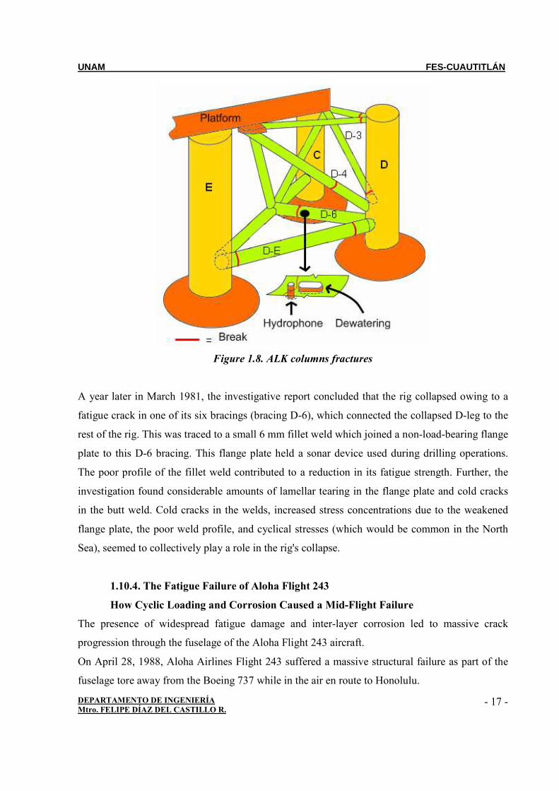
Figure 1.8. ALK columns fractures
A year later in March 1981, the investigative report concluded that the rig collapsed owing to a
fatigue crack in one of its six bracings (bracing D-6), which connected the collapsed D-leg to the
rest of the rig. This was traced to a small 6 mm fillet weld which joined a non-load-bearing flange
plate to this D-6 bracing. This flange plate held a sonar device used during drilling operations.
The poor profile of the fillet weld contributed to a reduction in its fatigue strength. Further, the
investigation found considerable amounts of lamellar tearing in the flange plate and cold cracks
in the butt weld. Cold cracks in the welds, increased stress concentrations due to the weakened
flange plate, the poor weld profile, and cyclical stresses (which would be common in the North
Sea), seemed to collectively play a role in the rig's collapse.
1.10.4. The Fatigue Failure of Aloha Flight 243
How Cyclic Loading and Corrosion Caused a Mid-Flight Failure
The presence of widespread fatigue damage and inter-layer corrosion led to massive crack
progression through the fuselage of the Aloha Flight 243 aircraft.
On April 28, 1988, Aloha Airlines Flight 243 suffered a massive structural failure as part of the
fuselage tore away from the Boeing 737 while in the air en route to Honolulu.
Page 19
UNAM FES-CUAUTITLÁN
DEPARTAMENTO DE INGENIERÍA Mtro. FELIPE DÍAZ DEL CASTILLO R.
- 18 -
It was later determined that the failure was caused by widespread fatigue damage in the
aluminum skin of the fuselage. It was calculated that this particular aircraft had experienced
89,090 flight cycles over its 19 year life span. What caused this failure, and how could it have
been prevented?
Figura 1.9. After 89,090 flight cycles on a 737-200, metal fatigue lets the top go in flight (28-
abril-1988)
Causes of Crack Growth in Aloha Flight 243
The investigation into the failure of Aloha Flight 243 concluded that the widespread fatigue
damage that led to the ultimate failure was caused by the aircraft’s exceptionally large number of
flight cycles and accelerated by the exposure of the aircraft to corrosive salt water vapor during
its inter-island flights. The combination of these two factors led to the creation of small crack
throughout the fuselage lap joints that eventually linked to form larger cracks and eventually fail
completely
The fuselage cracks originated in the lap joints of the aircraft skin. These horizontal seams
connect the aluminum sheets that make up the skin of the aircraft. The two sheets are overlapped
Page 20
UNAM FES-CUAUTITLÁN
DEPARTAMENTO DE INGENIERÍA Mtro. FELIPE DÍAZ DEL CASTILLO R.
- 19 -
and connected with usually two or three rows of rivets. The rivet heads are countersunk on the
exterior of the aircraft to maintain aerodynamics.
Every time the aircraft is pressurized, it stretches like an aluminum balloon. The pressure is
released when the aircraft returns to land. Because the Boeing 737 of Aloha Flight 243 was used
for inter-island flights, and would often fly several routes per day, it accumulated nearly 90,000
pressure cycles over its lifetime.
One of the primary accelerators of crack growth in aircraft fuselages is the presence of corrosion
between the two layers of the lap joint. Water can be pulled between the two sheets via capillary
action and begin to corrode the aluminum.
As the thickness of the aluminum skin is reduced through material loss, the stress induced by the
pressurization increases. The increased stress results in an accelerated crack growth rate. Because
Aloha Flight 243 was constantly exposed to the ocean air, the salt served to accelerate the
accumulation of corrosion in the lap joints and increase the overall crack growth rate.
Preventing Catastrophic Failures due to Widespread Fatigue Damage
After the failure of Aloha Flight 243, significant research was performed to understand the
mechanisms of crack growth in aluminum airframes. The recommendations were a combination
of structural changes to the airframe combined with more frequent and thorough inspection of
aircraft lap joints.
Circumferential strips of aluminum called tear straps were bonded to the skin at regular intervals.
When a crack progressing down a lap joint hit a tear strap, it tended to turn upwards and remain
within the frame bay of the aircraft. This would still be considered a failure, but was far
preferable to the crack unzipping the whole length of a fuselage.
In order to catch cracks before they reach critical lengths, aircraft operators have updated their
inspection techniques. In addition to visual inspections, non-destructive inspection (NDI)
methods are used to detect very small cracks that are difficult to be seen or may exist under paint,
as well as detect areas of corrosion between the layers of skin.
By instituting these prevention and inspection methods, airlines have managed to avoid a repeat
of the failure of Aloha Flight 243.
Page 21
UNAM FES-CUAUTITLÁN
DEPARTAMENTO DE INGENIERÍA Mtro. FELIPE DÍAZ DEL CASTILLO R.
- 20 -
BIBLIOGRAPHY
http://www.keytometals.com/page.aspx?ID=CheckArticle&site=kts&NM=142
http://www.asminternational.org/pdf/spotlights/jfap0502p011.pdf
http://en.wikipedia.org/wiki/Fatigue_(material)
http://en.wikipedia.org/wiki/Boston_Molasses_Disaster
http://www.suite101.com/content/the-fatigue-failure-of-aloha-flight-
243a123010#ixzz1Q0w95vxD
http://www.instron.co.uk/wa/applications/test_types/fatigue/