hine used to add energy to the gaseous fluid to inc ns are used where low pressures (from a few mm of w d comparatively large volume are required. They run peed, the casing and impeller usually built of shee FAN TYPES W FANS - the flow of the gases is parallel to the f tube axial vane axial Propeller CENTRIFUGAL FLOW FANS- the flow of gases depends ntrifugal action of the impeller or rotor. Straight blades Forward curved blades Backward curved blades Double curved blades
Transcript
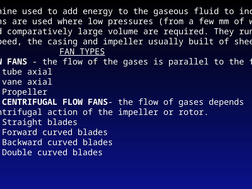
Fan is a machine used to add energy to the gaseous fluid to increase its pressure. Fans are used where low pressures (from a few mm of water to 50 mm Hg) and comparatively large volume are required. They run at rela-tively low speed, the casing and impeller usually built of sheet iron. FAN TYPES1) AXIAL FLOW FANS - the flow of the gases is parallel to the fan shaft. a. tube axial b. vane axial c. Propeller2) RADIAL OR CENTRIFUGAL FLOW FANS- the flow of gases depends upon the centrifugal action of the impeller or rotor. a. Straight blades b. Forward curved blades c. Backward curved blades d. Double curved blades
Propeller Fan Tubeaxial Fan Vaneaxial Fan
Air in
Air out
Motor
Rotor
Housing
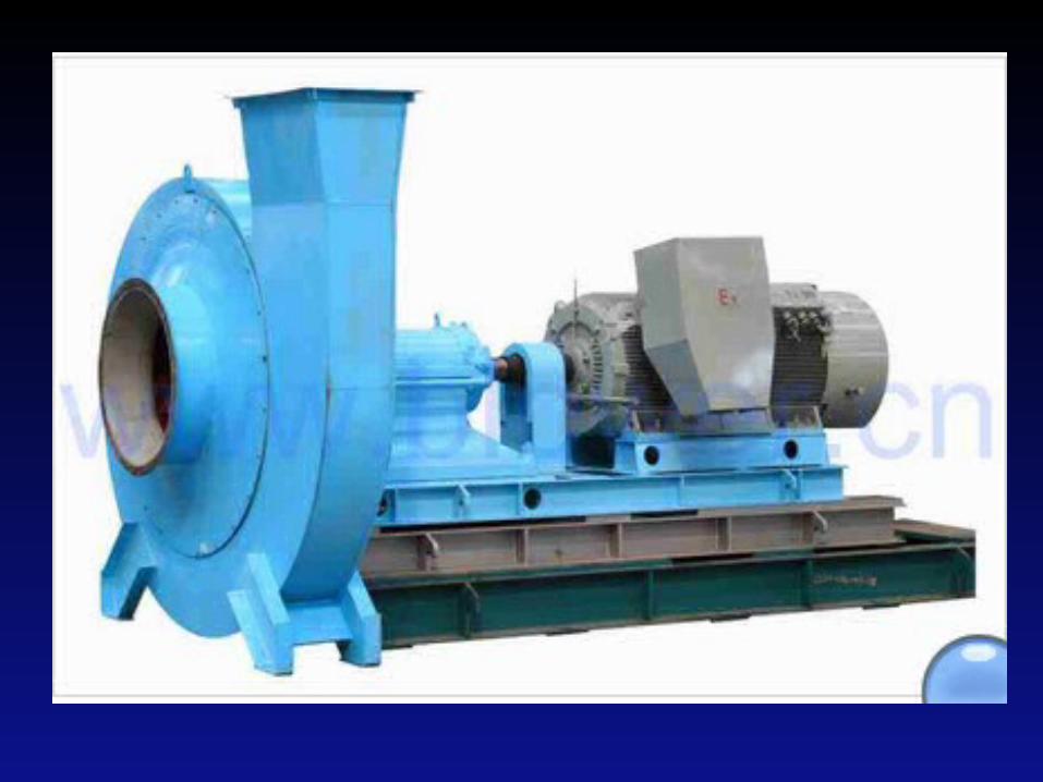
Centrifugal Fan
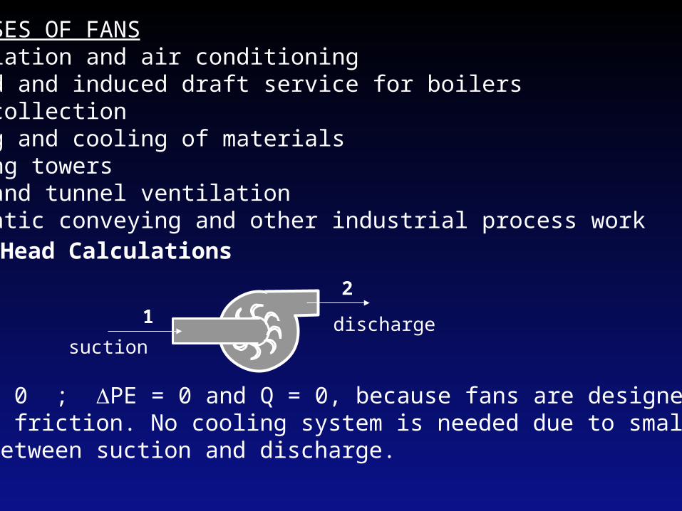
COMMON USES OF FANS1. Ventilation and air conditioning2. Forced and induced draft service for boilers3. Dust collection4. Drying and cooling of materials5. Cooling towers6. Mine and tunnel ventilation7. Pneumatic conveying and other industrial process work
Head Calculations
12
suctiondischarge
For a fan Z = 0 ; PE = 0 and Q = 0, because fans are designed toovercome fluid friction. No cooling system is needed due to small temperaturedifferential between suction and discharge.
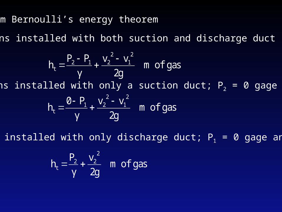
3. For fans installed with only discharge duct; P1 = 0 gage and v1 = 0
1. For fans installed with both suction and discharge duct
gas of m 2g
vvPPh
21
2212
t
γ
gas of m 2g
vvP0h
21
221
t
γ
2. For fans installed with only a suction duct; P2 = 0 gage
gas of m 2gvP
h2
22t
γ
From Bernoulli’s energy theorem
gas of m PP
h 12s γ
gas of m 2g
vvh
21
22
v
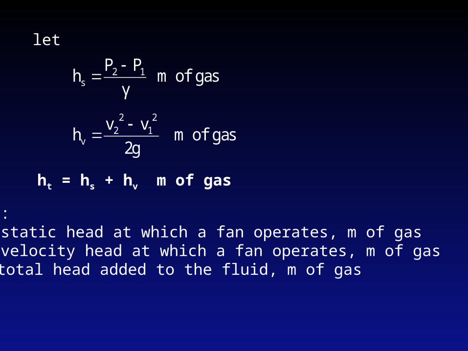
let
ht = hs + hv m of gas
Where:hs - static head at which a fan operates, m of gashv - velocity head at which a fan operates, m of gasht - total head added to the fluid, m of gas
Head Conversion: From m of gas to m of water
waterof m h
h
hw
gg
w
ggw ρ
ργ
γ
htw = hsw + hvw
Where:h - stands for ,total head, static head or velocity headw - refers to water; g - refers to gas
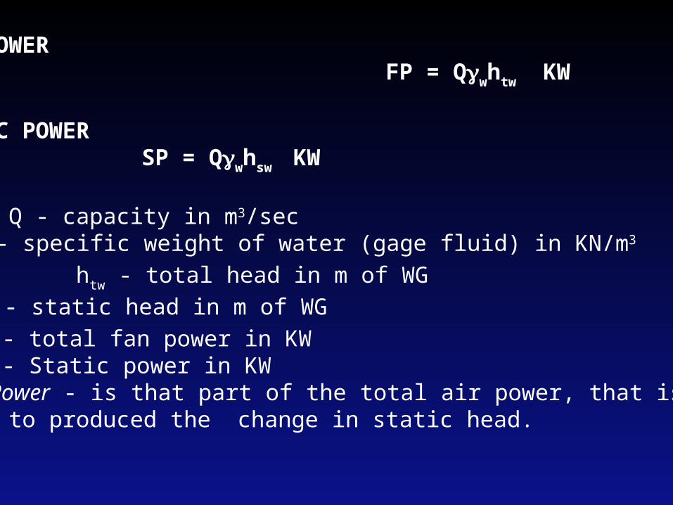
FAN POWER FP = Qwhtw KW STATIC POWER SP = Qwhsw KW
where Q - capacity in m3/sec w - specific weight of water (gage fluid) in KN/m3
htw - total head in m of WGhsw - static head in m of WGFP - total fan power in KWSP - Static power in KW
Static Power - is that part of the total air power, that is used to produced the change in static head.
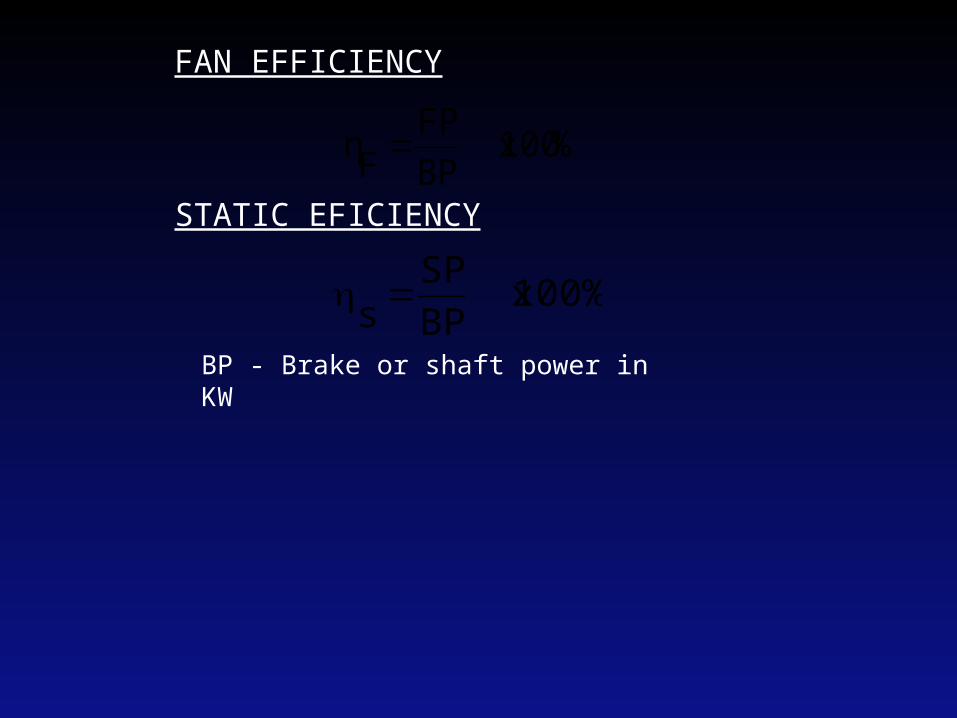
FAN EFFICIENCY STATIC EFICIENCY
% 100 xBPFP
Fη
100% xBPSP
s
BP - Brake or shaft power in KW
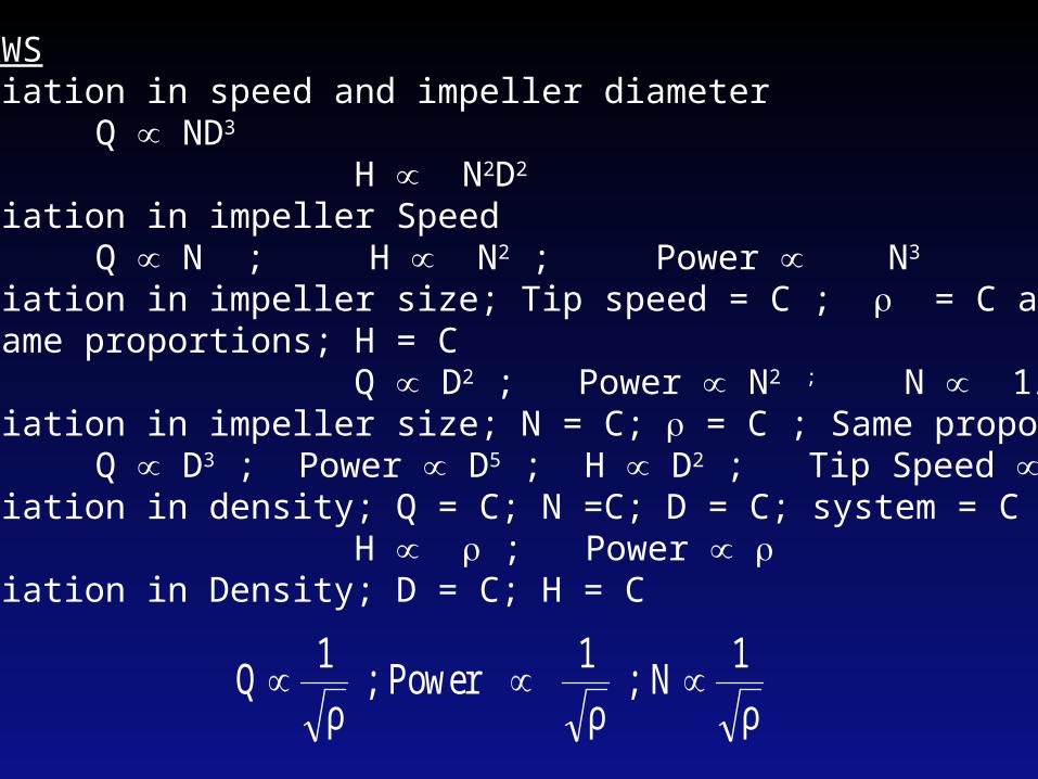
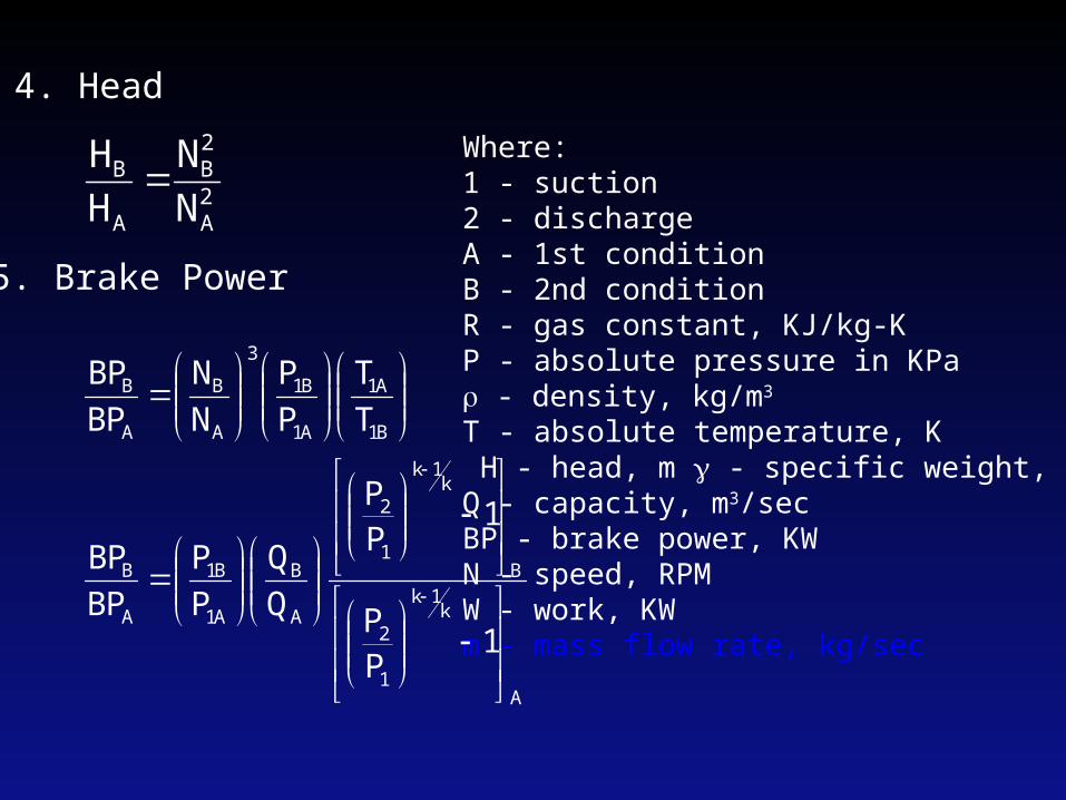
FAN LAWSA. Variation in speed and impeller diameter Q ND3
H N2D2
B. Variation in impeller Speed Q N ; H N2 ; Power N3
C. Variation in impeller size; Tip speed = C ; = C and same proportions; H = C Q D2 ; Power N2 ; N 1/DD. Variation in impeller size; N = C; = C ; Same proportions Q D3 ; Power D5 ; H D2 ; Tip Speed DE. Variation in density; Q = C; N =C; D = C; system = C H ; Power F. Variation in Density; D = C; H = C
ρ1N ;
ρ1 Power ;
ρ1Q
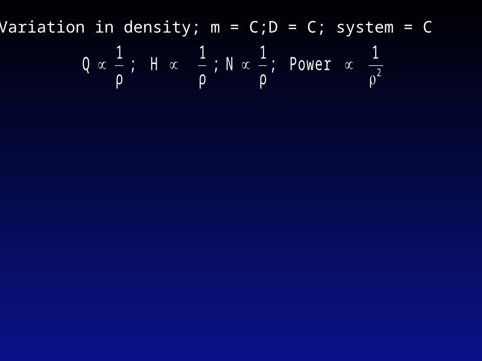
G. Variation in density; m = C;D = C; system = C
2
1 Power
; ρ1 N ;
ρ1 H ;
ρ1 Q
BLOWERS Blower is a machine used to compressed air or gas by centrifugal force to a final pressure not exceeding 241 KPa gage. Usually blower has no cooling system or it is not water cooled.COMPRESSION OF GASESThe design of blower is usually based upon either an adiabatic or isothermalcompression.
A. For Adiabatic or Isentropic Compression:
P
VP1
P2
1
2PVk = C
meters in head adiabatic - H /secm incapacity - Q
V Q whereHQW
1PP
1kQkP
W
PP
TT
3
1
k1k
1
21
k1k
1
2
1
2
γ
gas of m 1PP
1kg1000kRT
Hk
1k
1
21
B. For Isothermal Compression:
P
VP1
P2
1
2PV = C
meters PP
ln g
1000RTH
KW HQW
KW PP
lnmRT PP
ln QPW
CVPVP
1
21
1
21
1
21
2211
γ
where H - isothermal head in metersQ - capacity in m3/secg - gravitational acceleration in m\sec2
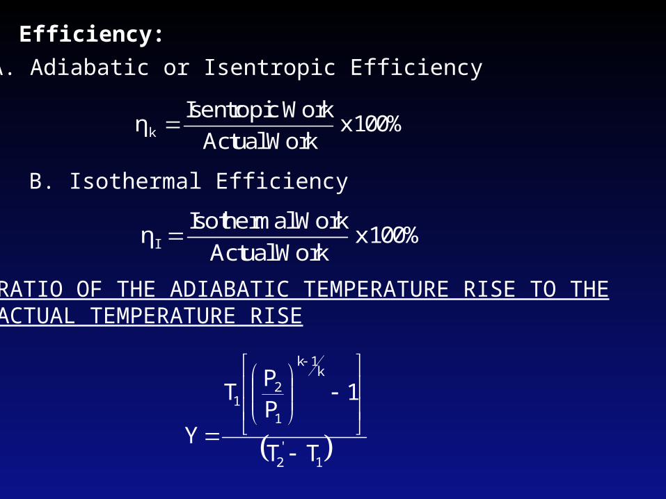
Efficiency:A. Adiabatic or Isentropic Efficiency
100% xWork Actual
Work Isentropick η
B. Isothermal Efficiency
100% xWork Actual
Work IsothermalI η
RATIO OF THE ADIABATIC TEMPERATURE RISE TO THEACTUAL TEMPERATURE RISE
1'2
k1k
1
21
TT
1PP
T
Y
RELATIONSHIP FOR CORRECTING PERFORMANCE CURVES 1. Volume Flow
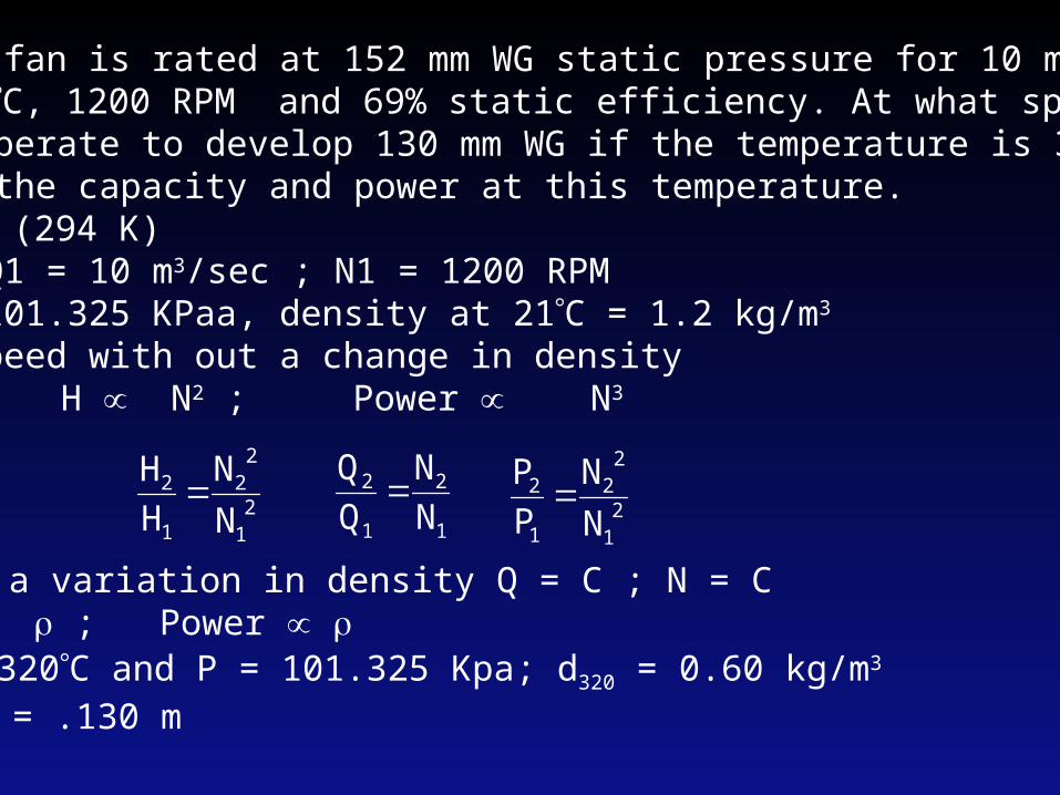
1. An industrial fan is rated at 152 mm WG static pressure for 10 m3/sec of air at 21C, 1200 RPM and 69% static efficiency. At what speed should this fan operate to develop 130 mm WG if the temperature is 320C? Also determine the capacity and power at this temperature.
Given: at 21C (294 K)H1 = .152 m; Q1 = 10 m3/sec ; N1 = 1200 RPM Assuming P = 101.325 KPaa, density at 21C = 1.2 kg/m3
At variable speed with out a change in density
Q N ; H N2 ; Power N3
21
22
1
2
NN
HH
For a variation in density Q = C ; N = CH ; Power
1
2
1
2
NN
QQ
2
1
22
1
2
NN
PP
At 320C and P = 101.325 Kpa; d320 = 0.60 kg/m3
H320 = .130 m
294
316
294
320
dd
HH
H2 = 1.06 x 10⁻⁷N22 H2 = H294
N2 = 1566 RPMQ2 = 13.05 m3/secQ2 = Q320
KW 1224BP0.69
HQBP
320
320320320
.
γ
2. Find the air power of an industrial fan that delivers 26 m3/sec of air through a duct 92 cm x 124 cm outlet. Static pressure is 127 mm WG. Air tempe- rature is 21C and barometric pressure is 760 mm Hg. ( 41 KW)
1
2
1.24 m0.92 m
Besides of centrifugal fans with low pressure, medium pressure, and high pressure, manufacturers also produce customs-made products to get the beat match between economy and performance.
FeaturesApplying optimizing design method, modular design, quality process control, and customs-made etc. different way to meet the different needs of the customs.The Max. Efficiency can be 90%, which is 5% higher than the competitors.Wide range of technical parameter ensures the fans run at its best efficiency at the specified applications.
Duty:Flow: 1~ 800 m3/s,Pressure: 300~ 50000Pa.Applications: Power station, Environmental protection, Mining, Metallurgy, Petro-chemical, Subway, tunnel, and wind tunnel etc.