1 ZIPP MANUFACTURING JAE Mini Sprint Fast Electric Outrigger A Zippkits R/C Boat Building Instructions 2011 Zipp Manufacturing - Frankfort, New York 13340 www.zippkits.com Toll Free (866) 922-ZIPP
Transcript
1
Z I P P M A N U FA C T U R I N G
JAE Mini Sprint
Fast Electric
Outrigger
A Zippkits R/C Boat
Building Instructions
2011 Zipp Manufacturing - Frankfort, New York 13340
www.zippkits.com
Toll Free (866) 922-ZIPP
2
The JAE series was designed and developed as a result of a joint venture between IMPBA Hall
of Fame member Rod Geraghty, David Hall, Ron Zaker Jr. & Martin Truex Jr.
The main difference between this hull and all the others is the use of sharp edges on the bottom
of the sponsons and tub, as opposed to curved surfaces. This helps break any surface tension
of the water and makes for a faster boat.
This design approach has been built, developed and tested a great deal.
The Mini Sprint is a new type of kit we call an ARR kit (Almost Ready to Run kit).
This kit features a level of pre-fabrication never before seen in a kit boat.
All of the hard work is already done for you, requiring only simple assembly and finishing.
The kit is not hard to assemble, as all of the hard stuff has been done for you.
That is no excuse to do a poor job with assembly. The better you build this boat, the better it will
run. Often the difference between an excellent building job and a poor one is a simple sanding
block.
A note about overhangs:
This boat is designed to shear water and prevent any capillary action of water. To do this the
tub, ski and sponsons have rear overhangs. These shear the water off and must be left in place
and not rounded in any way.
Take the time to read this entire manual, so that you are familiar with all the buildings steps and
their proper order. Take your time; make sure you understand everything before you do it and
you will be rewarded with an impressive running hull…
Note that the pictures in this manual may be of a different boat to better illustrate a point.
This kit is not a toy. Although R/C boating is a fun and rewarding hobby, it can be dangerous
if not done with common sense and safety in mind. Just about anyone should be able to
build this kit, but it should not be operated by children without close adult supervision.
The manufacturer assumes no liability for damages or other loss in the use of this product, as we have no control over the construction or end use of this product.
3
Tools and supplies needed to build
Sanding blocks with 80 and 150 grit paper
Drill with 1/16 and 3/32 bits
Square
Flat file
Round (3/16) file
5/16 and 3/8 open end wrenches
FLAT Workbench
Metric hex ball drivers
Building Jig
Medium CA glue and accelerator
Good quality 30 minute epoxy
Epoxy finishing resin
Spring clamps, paper clamps, c clamps, etc.
Razor blade or X-Acto knife
Masking tape
Waxed paper
Wood filler
Primer
Paint
4
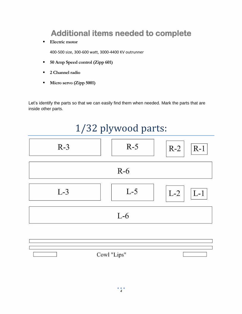
Additional items needed to complete Electric motor
Let’s identify the parts so that we can easily find them when needed. Mark the parts that are
inside other parts.
1/32 plywood parts:
5
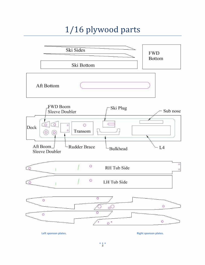
1/16 plywood parts
Left sponson plates. Right sponson plates.
6
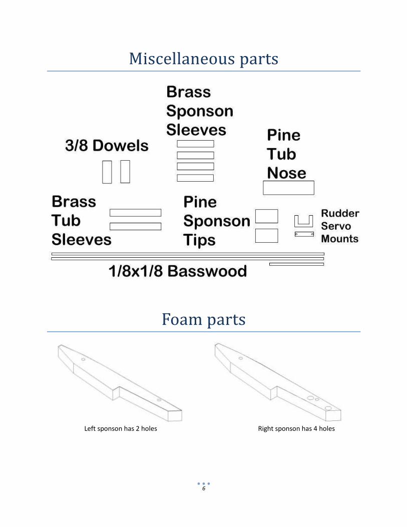
Miscellaneous parts
Foam parts
Left sponson has 2 holes Right sponson has 4 holes
7
Do an inventory of all the parts, to be sure that everything is there. If anything is missing
or damaged, contact us as soon as possible, so that we can get replacements to you quickly.
Tub Jig
We recommend that you make a jig for the tub.
This can be as simple as two straight pieces of ½ to ¾ inch thick wood.
It can be as elaborate as 1/16 by 1 inch aluminum angle with adjustment slots for different tub
widths.
Either way, you need something to clamp the tub sides to.
Every critical component on this hull depends on a straight, square tub.
Do whatever it takes to get it done correctly.
8
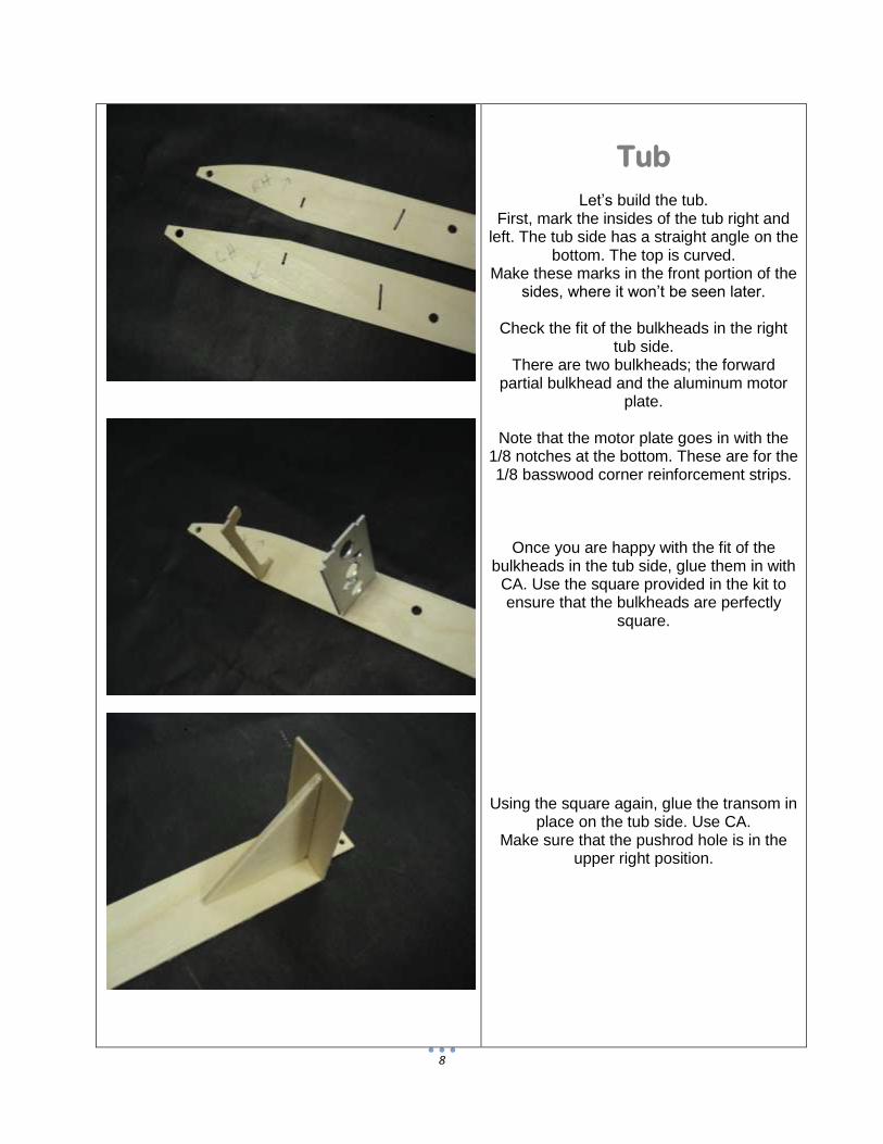
Tub
Let’s build the tub. First, mark the insides of the tub right and
left. The tub side has a straight angle on the bottom. The top is curved.
Make these marks in the front portion of the sides, where it won’t be seen later.
Check the fit of the bulkheads in the right
tub side. There are two bulkheads; the forward
partial bulkhead and the aluminum motor plate.
Note that the motor plate goes in with the
1/8 notches at the bottom. These are for the 1/8 basswood corner reinforcement strips.
Once you are happy with the fit of the bulkheads in the tub side, glue them in with
CA. Use the square provided in the kit to ensure that the bulkheads are perfectly
square.
Using the square again, glue the transom in place on the tub side. Use CA.
Make sure that the pushrod hole is in the upper right position.
9
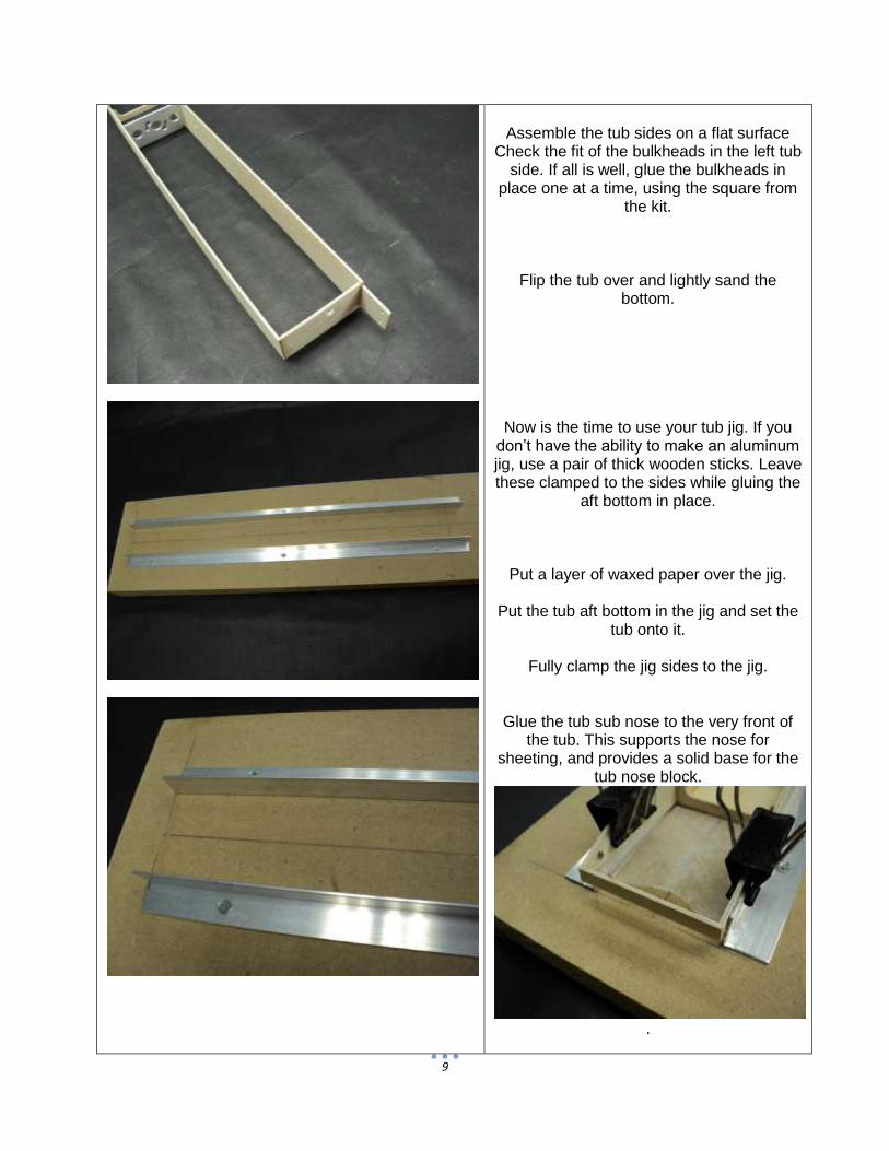
Assemble the tub sides on a flat surface
Check the fit of the bulkheads in the left tub side. If all is well, glue the bulkheads in
place one at a time, using the square from the kit.
Flip the tub over and lightly sand the bottom.
Now is the time to use your tub jig. If you don’t have the ability to make an aluminum jig, use a pair of thick wooden sticks. Leave these clamped to the sides while gluing the
aft bottom in place.
Put a layer of waxed paper over the jig.
Put the tub aft bottom in the jig and set the tub onto it.
Fully clamp the jig sides to the jig.
Glue the tub sub nose to the very front of the tub. This supports the nose for
sheeting, and provides a solid base for the tub nose block.
.
10
Pre cut the 1/8 inch square basswood strips
to fit in the tub on both sides (against the bottom), but do not glue.
These strips touch the forward bulkhead
and transom. Cut slightly long. Trim for an exact fit.
Save the cutoff pieces.
Using epoxy, glue the tub aft bottom in place. Make sure that the bottom extends to
the front bulkhead. It should cover the full 1/16 inch bulkhead. Later on, we will sand
this to match the angle of the tub sides. Leave a small 1/16 overhang at the rear of
the tub. Do not sand this off.
The aft bottom sheet is pre cut to the correct length. Make the front of this flush with the front of the first bulkhead, and the
rear overhang will be correct.
While the epoxy is still wet, glue in the two basswood strips.
Use small weights if needed to keep them in place.
Use two pieces of basswood (from the cutoffs) to reinforce the transom on each
side, inside the tub. Leave these slightly higher than the tub
side. They will be sanded flush later.
11
Use another piece of basswood on the tub bottom to transom.
Glue these in place with epoxy.
Also glue the rudder brace in place at this time.
This brace goes inside the tub extension of the right tub side.
Allow to cure.
Remove the tub from the jig.
Glue the forward bottom in place with epoxy. Be sure to sand the angle into the aft sheet so that it matches the tub sides.
The forward bottom sheet should cover the bevel on the aft sheeting and be left square.
Do not sand the rear of the forward sheeting; it needs to have a sharp edge for
the water to shear off. See drawing.
Put the tub back into the jig, upside down. This will help keep the tub square during
the installation of the forward bottom.
Allow to cure.
12
When the tub bottom has cured, lets move
on to boom tube alignment. This is probably the most critical step in the
assembly, so take all the time needed to get this right.
Grab the two brass boom tube sleeves, and use 80 grit paper to rough the last 1/8 inch
or so of each end.
Put the rear tube doublers in place and slip a boom tube sleeve and carbon boom tube
through the tub and doublers.
Measure the carbon tube on each side of the tub, and center it. Make some pencil marks on the tube, on the outsides of the
tub so that you can quickly center the tube later.
Do the same for the forward boom tube and
doublers.
The forward boom tube doublers line up with the forward boom tube holes. They
only align correctly one way, so be sure that the orientation is correct before you mix any
glue.
Weight the tub so that it is flat on the bench.
Clamp the doublers in place without glue and measure the ends of the tubes.
Both sides of the tubes should be the same distance from the bench.
13
If not, loosen the clamps and adjust the doublers until they are.
If the holes now have to be sanded to fit, you must sand them and repeat the
measuring process. If needed, you can use a round file to
elongate the holes in the tub. Leave the holes in the doublers the original
size.
This is a critical step in the assembly, and if done incorrectly, your hull will never handle
properly.
When you are happy with the height of the tubes above the bench, check to see that the tubes are square front to back with the
square provided in the kit. When you have checked and double
checked that the boom tubes are straight and square to the world, remove the
clamps, but leave everything in place.
Mix up some 30 minute epoxy, and coat the doublers where they will be in contact with
the tub sides. Align the doublers and clamp in place.
Quickly check your measurements and
square several times, and make any tiny adjustments before the epoxy starts to cure.
Use any excess epoxy to build a small fillet around the sleeves and doublers. Clamp in
place.
Set aside for at least 3 hours. Repeat for the front boom tubes. Be sure
everything is perfect before you walk away…
Once everything has cured, sand the brass tub sleeves flush with the tub sides.
14
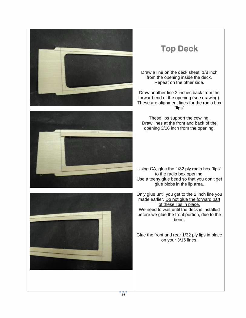
Top Deck
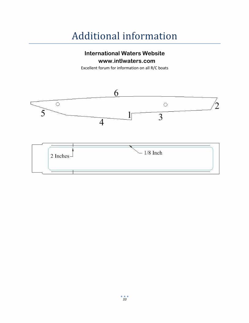
Draw a line on the deck sheet, 1/8 inch from the opening inside the deck.
Repeat on the other side.
Draw another line 2 inches back from the forward end of the opening (see drawing). These are alignment lines for the radio box
“lips”
These lips support the cowling. Draw lines at the front and back of the opening 3/16 inch from the opening.
Using CA, glue the 1/32 ply radio box “lips” to the radio box opening.
Use a teeny glue bead so that you don’t get glue blobs in the lip area.
Only glue until you get to the 2 inch line you made earlier. Do not glue the forward part
of these lips in place. We need to wait until the deck is installed
before we glue the front portion, due to the bend.
Glue the front and rear 1/32 ply lips in place on your 3/16 lines.
15
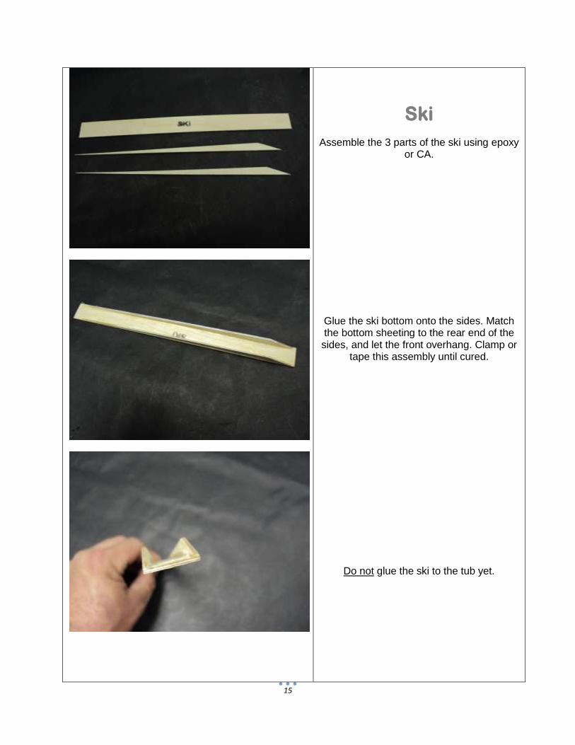
Ski
Assemble the 3 parts of the ski using epoxy or CA.
Glue the ski bottom onto the sides. Match the bottom sheeting to the rear end of the sides, and let the front overhang. Clamp or
tape this assembly until cured.
Do not glue the ski to the tub yet.
16
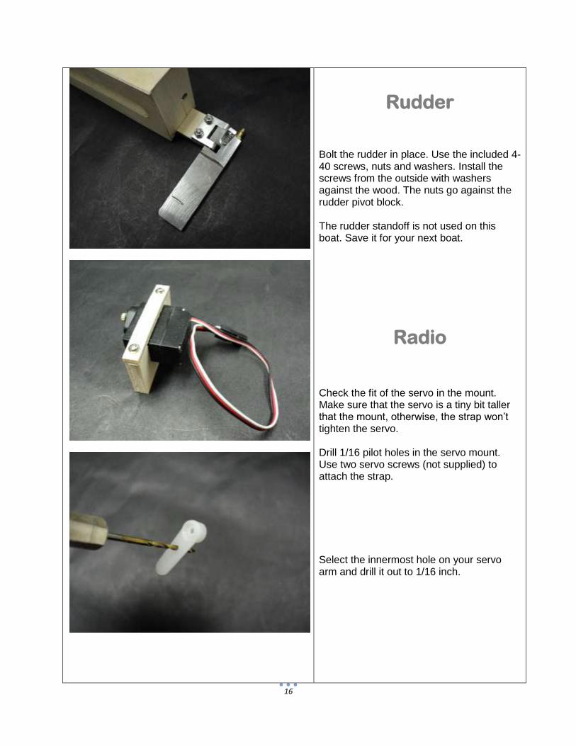
Rudder
Bolt the rudder in place. Use the included 4-40 screws, nuts and washers. Install the screws from the outside with washers against the wood. The nuts go against the rudder pivot block. The rudder standoff is not used on this boat. Save it for your next boat.
Radio Check the fit of the servo in the mount. Make sure that the servo is a tiny bit taller that the mount, otherwise, the strap won’t tighten the servo. Drill 1/16 pilot holes in the servo mount. Use two servo screws (not supplied) to attach the strap. Select the innermost hole on your servo arm and drill it out to 1/16 inch.
17
Attach the “Z” bend in the pushrod. Put this on the servo. Make sure that the servo arm is straight up. Make a mark on the tub floor, ½ inch forward of the transom brace. Slide the pushrod thru the hole in the transom, and into the rudder pushrod connector. Glue the servo mount to the tub floor, adjusting the position of the mount so that the rudder pushrod aligns with the rudder, and it matches your mark. The servo may touch the tub side. This is okay. Don’t get any glue on the servo or wire. Allow to cure.
18
Sealing Remove everything from the boat in preparation for sealing. Use epoxy finishing resin (or West Systems epoxy) to seal the inside of the tub. Be sure to seal around the boom tube sleeves, pushrod hole and all around the servo mount. Use any excess epoxy to seal the ski (inside and out), as well as one side of the radio box top. Set these on waxed paper while they cure. You can also seal the servo strap. If you have any epoxy left, seal the outside of the tub bottom. You can set the tub upside down on waxed paper to cure. Allow to cure overnight. Cut the two pieces of 1/8 square basswood to 14-3/8 inches. Put these in a cup or small soda bottle with about 3 inches of water inside. Let sit for 15 minutes.
19
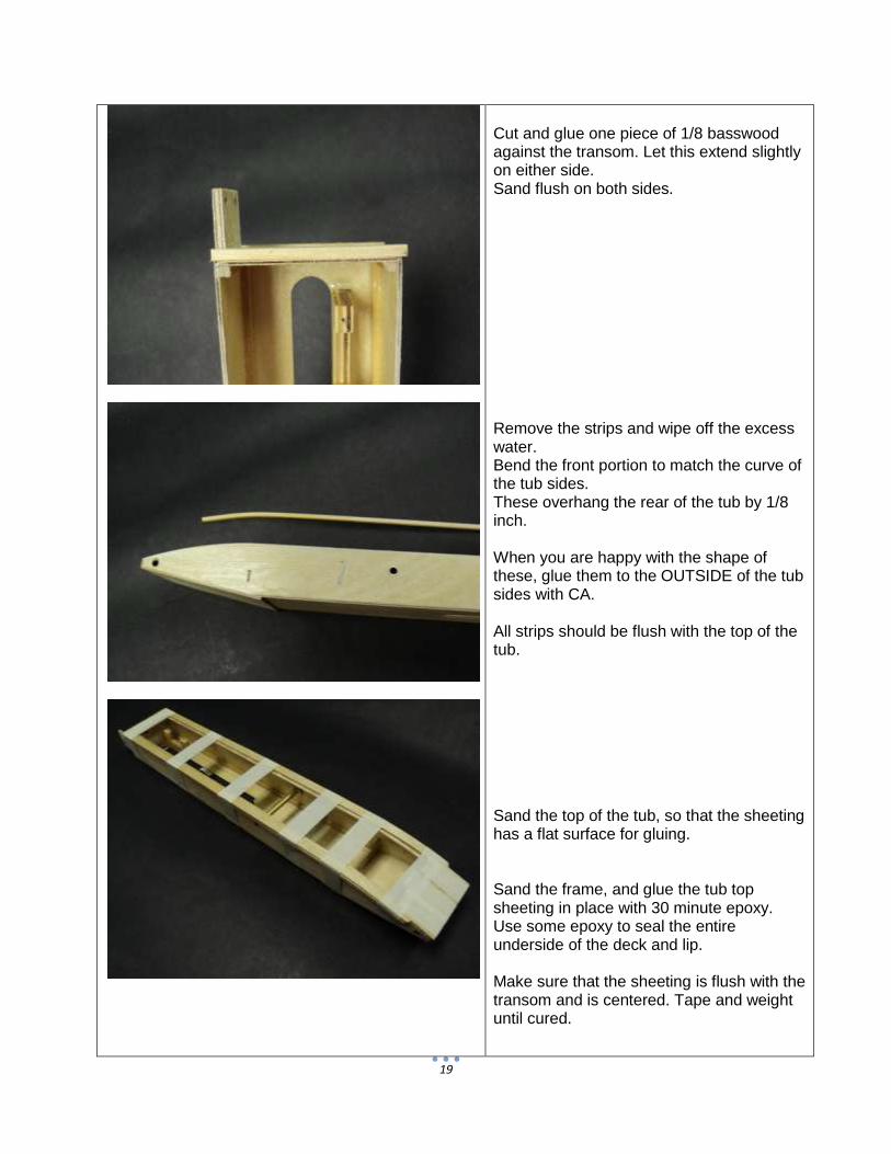
Cut and glue one piece of 1/8 basswood against the transom. Let this extend slightly on either side. Sand flush on both sides. Remove the strips and wipe off the excess water. Bend the front portion to match the curve of the tub sides. These overhang the rear of the tub by 1/8 inch. When you are happy with the shape of these, glue them to the OUTSIDE of the tub sides with CA. All strips should be flush with the top of the tub. Sand the top of the tub, so that the sheeting has a flat surface for gluing. Sand the frame, and glue the tub top sheeting in place with 30 minute epoxy. Use some epoxy to seal the entire underside of the deck and lip. Make sure that the sheeting is flush with the transom and is centered. Tape and weight until cured.
20
Once the top sheeting has cured, glue and clamp the forward “lips” to the deck. Sand the front of the tub flat and square. Glue the pine tub nose block to the front of the tub. Shape the block to match the tub. Finish the nose block with a round, blunt nose.
21
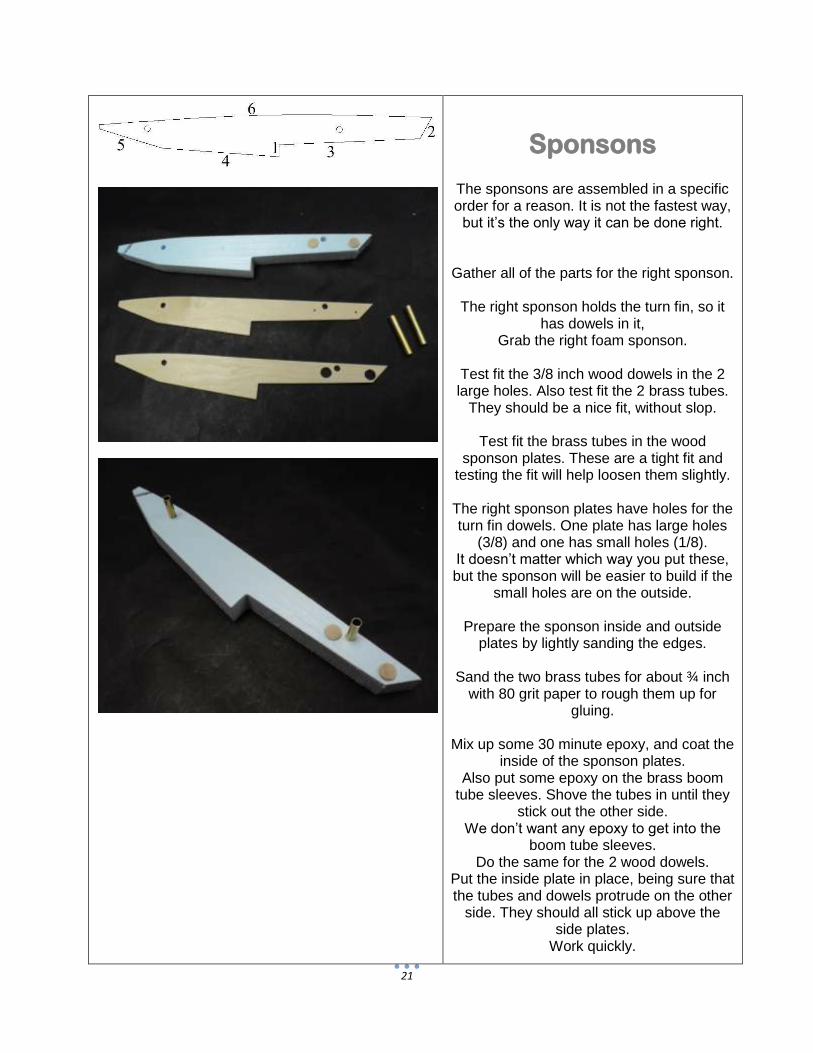
Sponsons
The sponsons are assembled in a specific order for a reason. It is not the fastest way,
but it’s the only way it can be done right.
Gather all of the parts for the right sponson.
The right sponson holds the turn fin, so it has dowels in it,
Grab the right foam sponson.
Test fit the 3/8 inch wood dowels in the 2 large holes. Also test fit the 2 brass tubes.
They should be a nice fit, without slop.
Test fit the brass tubes in the wood sponson plates. These are a tight fit and
testing the fit will help loosen them slightly.
The right sponson plates have holes for the turn fin dowels. One plate has large holes
(3/8) and one has small holes (1/8). It doesn’t matter which way you put these, but the sponson will be easier to build if the
small holes are on the outside.
Prepare the sponson inside and outside plates by lightly sanding the edges.
Sand the two brass tubes for about ¾ inch
with 80 grit paper to rough them up for gluing.
Mix up some 30 minute epoxy, and coat the
inside of the sponson plates. Also put some epoxy on the brass boom
tube sleeves. Shove the tubes in until they stick out the other side.
We don’t want any epoxy to get into the boom tube sleeves.
Do the same for the 2 wood dowels. Put the inside plate in place, being sure that the tubes and dowels protrude on the other
side. They should all stick up above the side plates.
Work quickly.
22
Put the other sponson plate in place, aligning the brass sleeves and dowels.
Make sure that the sleeves and dowels go through both sponson plates.
The tubes and dowels should protrude through, and be flush with the outside plate
Use tape and small weights to hold the
sponson and allow to cure on waxed paper.
While the right sponson is curing, you can glue the left sponson. Everything is the
same, except the left sponson has only the two tubes.
*Make sure that the left sponson is a mirror image of the right*
With the right sponson on it’s right (outside)
side, and the left sponson on it’s left (outside) side, both sets of brass sleeves
should be sticking out. Glue the tubes and plates as before, and
weight or clamp until cured.
Be sure of this, as this is one of those critical points.
That said, we do offer replacement sponson
kits…
When the sponson sides are cured, let’s do the sheeting. This is where the strange
order comes in. The sheeting is done in this order because it has to overlap in a specific
way. Follow along and you won’t have any
trouble. If something doesn’t seem to fit, stop and find out why. Epoxy is impossible
to remove from foam…
Grab all the sheeting pieces, including the ones you marked earlier.
Use a file to sharpen the inside corner of the sponson step as shown.
23
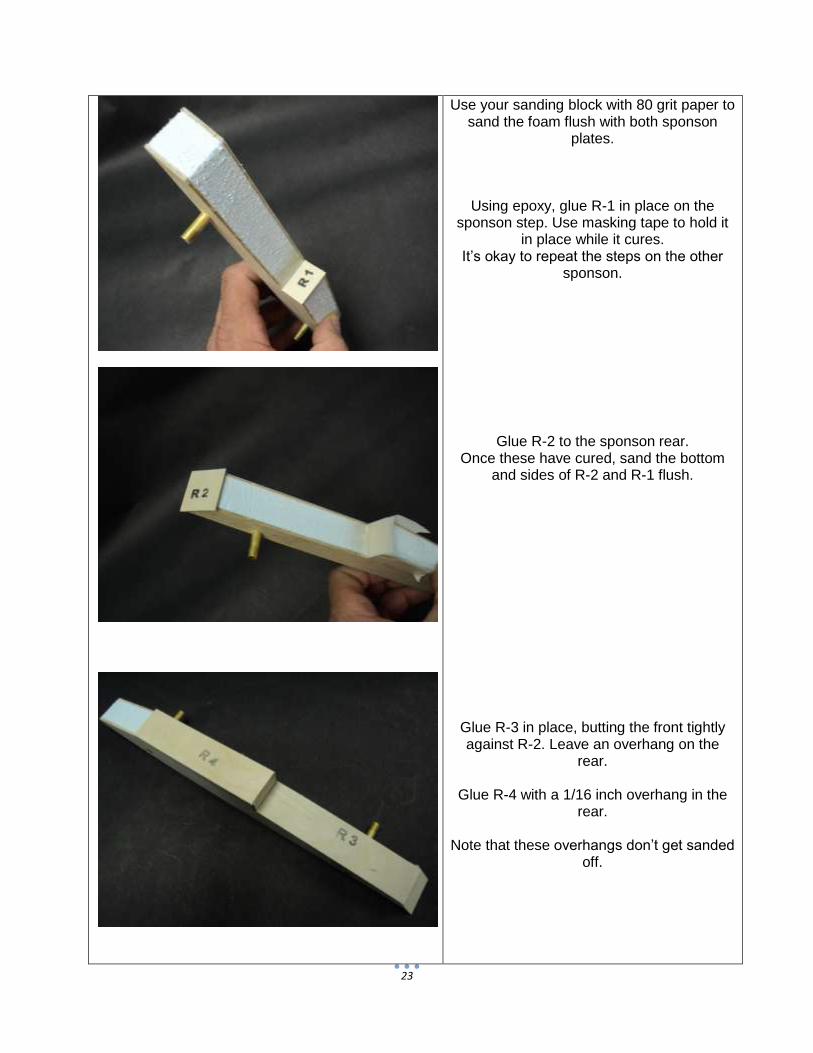
Use your sanding block with 80 grit paper to sand the foam flush with both sponson
plates.
Using epoxy, glue R-1 in place on the sponson step. Use masking tape to hold it
in place while it cures. It’s okay to repeat the steps on the other
sponson.
Glue R-2 to the sponson rear. Once these have cured, sand the bottom
and sides of R-2 and R-1 flush.
Glue R-3 in place, butting the front tightly against R-2. Leave an overhang on the
rear.
Glue R-4 with a 1/16 inch overhang in the rear.
Note that these overhangs don’t get sanded
off.
24
Sand the top of R-2, and glue the sponson top on (R-6).
Once R-4 is cured, sand the front of R-4 flush with the forward bottom. This is
exactly like the forward tub bottom. Do not round any corners.
Glue R-5 in place. Match the rear to just cover the bevel you sanded in R-4. Leave
the rear of this square, just like the tub bottom.
25
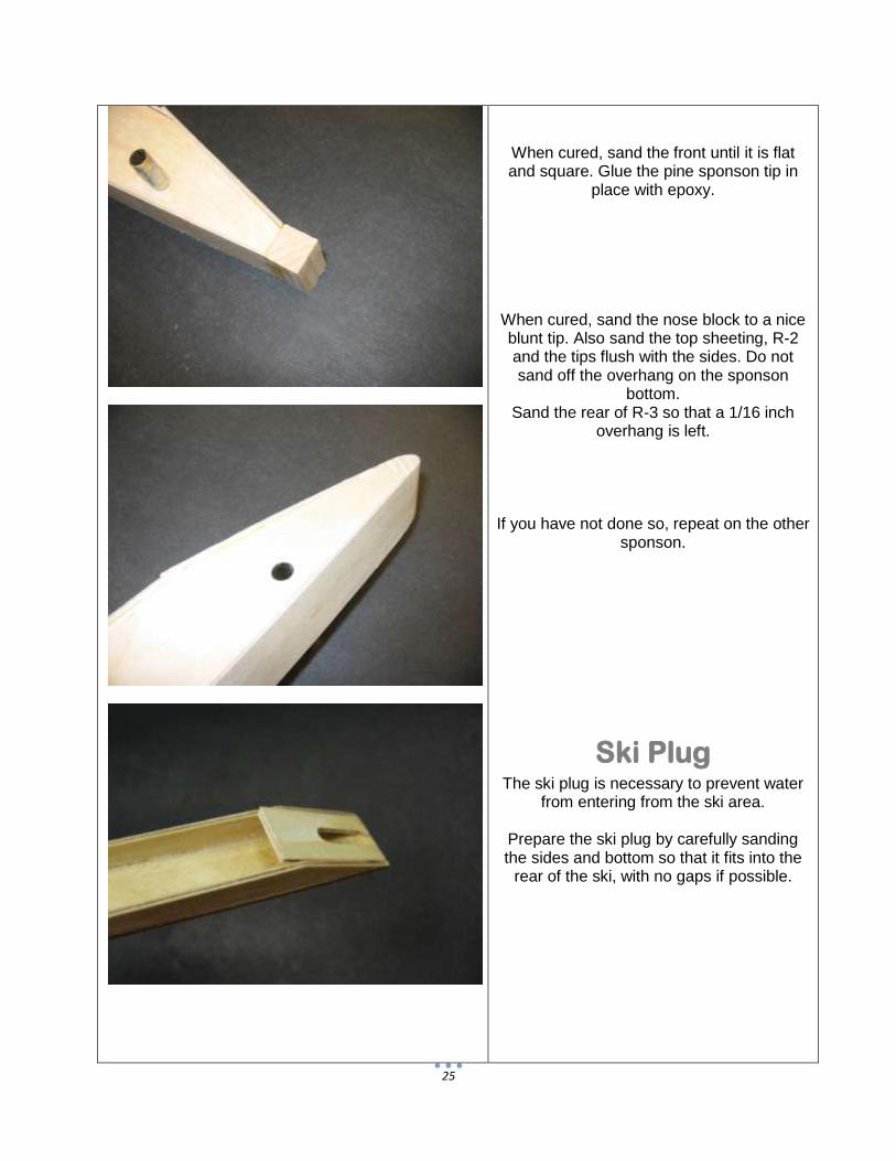
When cured, sand the front until it is flat and square. Glue the pine sponson tip in
place with epoxy.
When cured, sand the nose block to a nice blunt tip. Also sand the top sheeting, R-2 and the tips flush with the sides. Do not sand off the overhang on the sponson
bottom. Sand the rear of R-3 so that a 1/16 inch
overhang is left.
If you have not done so, repeat on the other sponson.
Ski Plug The ski plug is necessary to prevent water
from entering from the ski area.
Prepare the ski plug by carefully sanding the sides and bottom so that it fits into the
rear of the ski, with no gaps if possible.
26
Glue the ski plug in place with the opening towards the bottom.
Sand the top of the plug flush with the top of the ski.
Shaft
Test fit the ski to the tub.
The rear of the ski should line up with the rear of the transom, and the front should
blend into the tub bottom. Sand the front of the ski sheeting so that it blends to the tub
bottom. Measure from both sides and make small
alignment marks for the ski.
Using 30 minute epoxy, glue the ski in place. Be sure that the inside of the ski is
sealed with epoxy. Tape and weight the ski, check alignment,
and allow to cure.
27
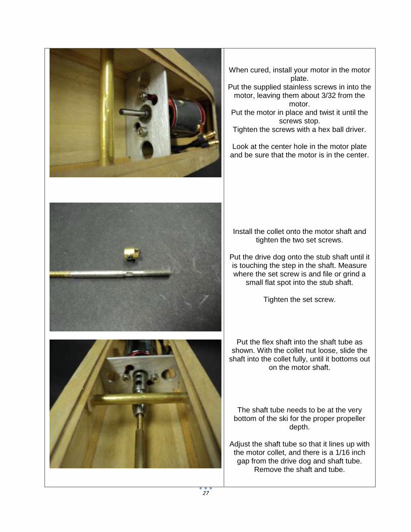
When cured, install your motor in the motor plate.
Put the supplied stainless screws in into the motor, leaving them about 3/32 from the
motor. Put the motor in place and twist it until the
screws stop. Tighten the screws with a hex ball driver.
Look at the center hole in the motor plate
and be sure that the motor is in the center.
Install the collet onto the motor shaft and tighten the two set screws.
Put the drive dog onto the stub shaft until it is touching the step in the shaft. Measure where the set screw is and file or grind a
small flat spot into the stub shaft.
Tighten the set screw.
Put the flex shaft into the shaft tube as shown. With the collet nut loose, slide the
shaft into the collet fully, until it bottoms out on the motor shaft.
The shaft tube needs to be at the very bottom of the ski for the proper propeller
depth.
Adjust the shaft tube so that it lines up with the motor collet, and there is a 1/16 inch gap from the drive dog and shaft tube.
Remove the shaft and tube.
28
Try to use extra epoxy here. Tape the plug in place, then set the boat so that the epoxy
forms a fillet inside, to help seal the plug from water.
When cured, fit the shaft tube.
You can use a round file to angle the hole in the ski plug for the tube.
Tack the tube in place with CA when
satisfied that there is a 1/16 gap for the drive dog and the front is aligned with the
motor..
Double check that the tube is aligned correctly.
If all is well, glue in place with epoxy.
Do this in several places inside the ski.
Turn Fin Mark the center of the turn fin dowels. Drill 3/32 pilot holes on your marks. Attach the turn fin with the supplied sheet metal screws and washers. Note that you can later fine tune the fin with the oversized holes.
Remove everything in preparation for
finishing.
29
Finishing
Sand the tub and sponsons, but be sure to leave the overhangs.
Fill any holes or imperfections with wood filler.
Sand everything with 150.
Seal the tub and sponsons with epoxy finishing resin or West Systems epoxy.
Be sure that all wood is sealed. Scrape off as much epoxy as you can. It will
make sanding easier. Also seal the other side of the radio box
top.
When cured, sand with 220 and recoat with epoxy. This coat will use far less resin than
the first.
When this cures, wet sand everything with 220.
If you are painting now is the time for primer. Wet sand the primer with 400, and use spot putty to fill any imperfections. Wet sand with 400 and lay on a heavy coat of primer. Wet sand with 600-800 and paint.
30
Final Assembly
Assemble the boom tubes with the tub and sponsons.
Push on the clear plastic boom retainers.
Put these on each side of the tub. Make the boom tubes flush with the outside end on the brass sleeves in the sponsons.
When everything is looking good, drill a 3/32 hole through the brass boom tube
sleeve and the boom tube. Put the supplied 2-56 screw and locknut in place. Do this for
all 4 corners.
Center the sponsons in the tub.
Use the boom retainers against the tub to keep the tubes in place.
When you are happy that the tub is centered, put a zip tie on each retainer and
trim. ,
31
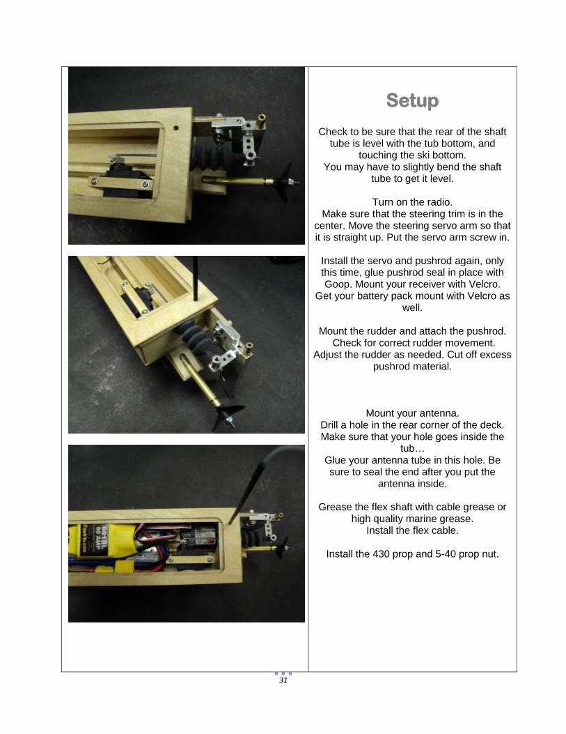
Setup
Check to be sure that the rear of the shaft tube is level with the tub bottom, and
touching the ski bottom. You may have to slightly bend the shaft
tube to get it level.
Turn on the radio. Make sure that the steering trim is in the
center. Move the steering servo arm so that it is straight up. Put the servo arm screw in.
Install the servo and pushrod again, only this time, glue pushrod seal in place with Goop. Mount your receiver with Velcro.
Get your battery pack mount with Velcro as well.
Mount the rudder and attach the pushrod.
Check for correct rudder movement. Adjust the rudder as needed. Cut off excess
pushrod material.
Mount your antenna. Drill a hole in the rear corner of the deck. Make sure that your hole goes inside the
tub… Glue your antenna tube in this hole. Be sure to seal the end after you put the
antenna inside.
Grease the flex shaft with cable grease or high quality marine grease.
Install the flex cable.
Install the 430 prop and 5-40 prop nut.
32
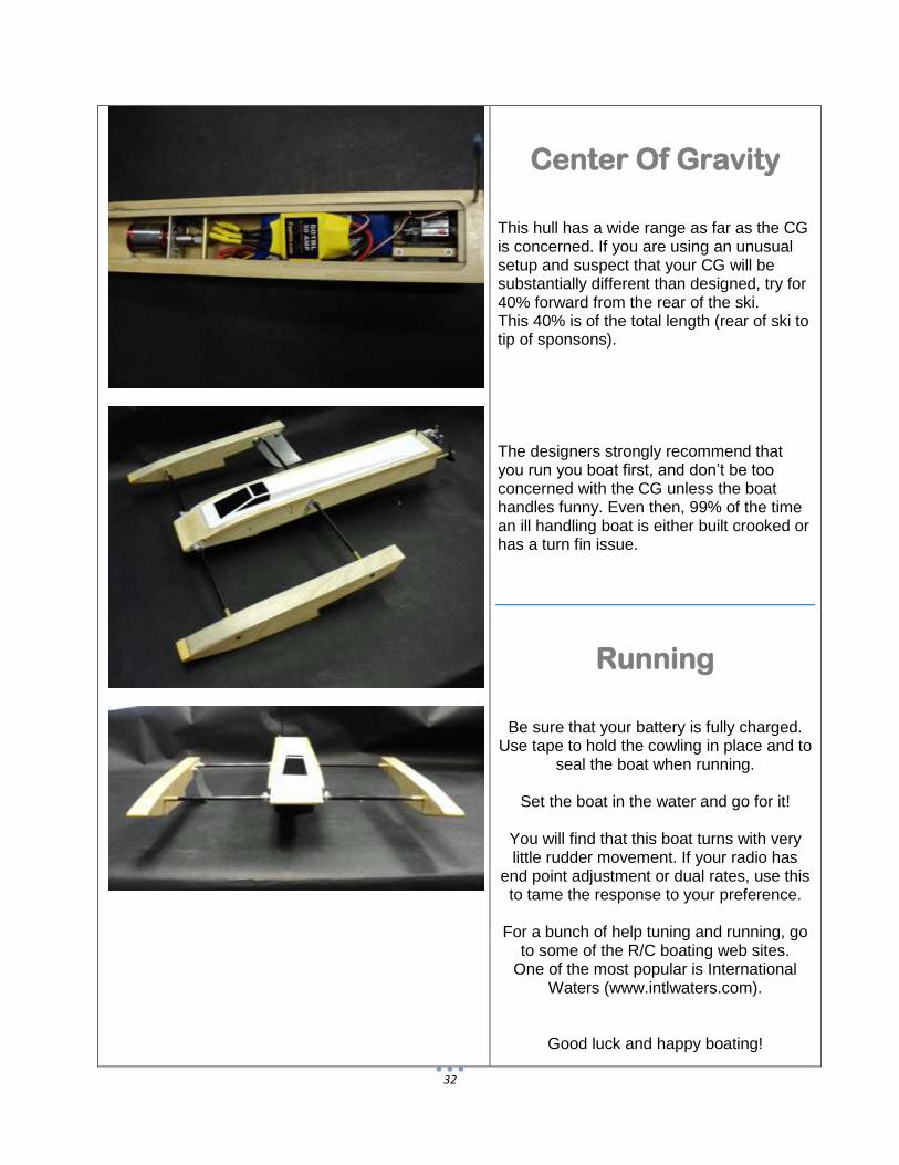
Center Of Gravity
This hull has a wide range as far as the CG is concerned. If you are using an unusual setup and suspect that your CG will be substantially different than designed, try for 40% forward from the rear of the ski. This 40% is of the total length (rear of ski to tip of sponsons). The designers strongly recommend that you run you boat first, and don’t be too concerned with the CG unless the boat handles funny. Even then, 99% of the time an ill handling boat is either built crooked or has a turn fin issue.
Running
Be sure that your battery is fully charged. Use tape to hold the cowling in place and to
seal the boat when running.
Set the boat in the water and go for it!
You will find that this boat turns with very little rudder movement. If your radio has
end point adjustment or dual rates, use this to tame the response to your preference.
For a bunch of help tuning and running, go
to some of the R/C boating web sites. One of the most popular is International