Fast-electron refluxing effects on anisotropic hard-x-ray emission fromintense laser-plasma interactions
McKeever, K., Makita, M., Nersisyan, G., Dzelzainis, T., White, S., Kettle, B., Dromey, B., Zepf, M., Sarri, G.,Doria, D., Ahmed, H., Lewis, C. L. S., & Riley, D. (2015). Fast-electron refluxing effects on anisotropic hard-x-rayemission from intense laser-plasma interactions. Physical Review E, 91(3), [033107].https://doi.org/10.1103/PhysRevE.91.033107
Published in:Physical Review E
Document Version:Publisher's PDF, also known as Version of record
Queen's University Belfast - Research Portal:Link to publication record in Queen's University Belfast Research Portal
General rightsCopyright for the publications made accessible via the Queen's University Belfast Research Portal is retained by the author(s) and / or othercopyright owners and it is a condition of accessing these publications that users recognise and abide by the legal requirements associatedwith these rights.
Take down policyThe Research Portal is Queen's institutional repository that provides access to Queen's research output. Every effort has been made toensure that content in the Research Portal does not infringe any person's rights, or applicable UK laws. If you discover content in theResearch Portal that you believe breaches copyright or violates any law, please contact [email protected].
Fast-electron refluxing effects on anisotropic hard-x-ray emissionfrom intense laser-plasma interactions
K. McKeever, M. Makita, G. Nersisyan, T. Dzelzainis, S. White, B. Kettle, B. Dromey,M. Zepf, G. Sarri, D. Doria, H. Ahmed, C. L. S. Lewis, and D. Riley*
Centre for Plasma Physics, School of Mathematics and Physics, Queen’s University Belfast, University Road,Belfast BT7 1NN, United Kingdom
A. P. L. RobinsonCentral Laser Facility, Rutherford-Appleton Laboratory, Chilton, Didcot OX11 OQX, United Kingdom
(Received 17 May 2014; revised manuscript received 3 February 2015; published 16 March 2015)
Fast-electron generation and dynamics, including electron refluxing, is at the core of understandinghigh-intensity laser-plasma interactions. This field is itself of strong relevance to fast ignition fusion and thedevelopment of new short-pulse, intense, x-ray, γ -ray, and particle sources. In this paper, we describe experimentsthat explicitly link fast-electron refluxing and anisotropy in hard-x-ray emission. We find the anisotropy in x-rayemission to be strongly correlated to the suppression of refluxing. In contrast to some previous work, the peak ofemission is directly along the rear normal to the target rather than along either the incident laser direction or thespecular reflection direction.
In high-intensity laser-plasma interactions, it is commonto generate a population of so called fast (or hot) electronsvia absorption mechanisms such as resonance absorption andJ×B acceleration [1]. Typical fast-electron energies rangefrom several tens of keV to several MeV [2–7] depending onthe intensity of the laser and the wavelength. It is commonto characterize them by an effective temperature even ifthey do not strictly follow a Maxwellian distribution. Thiseffective temperature is usually greatly in excess of theso called “thermal” temperature of the plasma that mayarise as a result of collisional absorption processes such asinverse bremsstrahlung. The dynamics of fast electrons as theypenetrate a solid density target are of great interest, partly dueto their relevance to fast ignition fusion schemes and partly dueto the central role of electron dynamics in the developmentof laser-based ion acceleration schemes [8] and x-ray andγ -ray sources that can be used in a variety of scientificapplications [9–12]. A phenomenon that has been previouslyobserved is the refluxing of electrons. In this process, fastelectrons created from the laser plasma interaction can travelthrough the foil until they reach the rear, where space-chargeeffects prevent most of them leaving the foil but pull them backinto the foil after a change of direction. A small number of veryenergetic electrons will escape the target until space chargeprevents further losses. This depends on the size and geometryof the target as well as irradiation conditions. The efficiencyof refluxing has been discussed by Myatt et al. [13], whopresent estimates based on a capacitive model for picosecondirradiation at 1.06 μm. For our conditions with mm sizedtargets and 2 × 10¹⁸ W cm−2 irradiance (see below), we expectin excess of 99% efficiency, similar to that assumed by Quinnet al. [14]. In the case of bare foils, a retarding electricfield caused by the escape of charge pulls back electrons.When a dielectric layer is added, this retarding electric field
penetrates into the dielectric and causes electrical breakdown,as discussed by Tikhonchuk [15]. This breakdown dissipatesenergy, and a return current can neutralize the fast electroncurrent, thus allowing fast electrons to be deposited in thedielectric layer and not be refluxed to the metallic foil. Therefluxing process has previously been observed via its effecton K-α radiation emission [13,16,17] and also as transverserefluxing from target edges in limited area targets [18]. Anotherimportant characteristic of intense laser-plasma interaction,seen at high intensity, is the anisotropy in hard-x-ray emissionthat can result from beamlike behavior of fast electrons,e.g., [19,20].
In this paper, we discuss the coupling of these two effectsthrough the observation of hard-x-ray emission that changesfrom isotropic to anisotropic as we introduce a layer of epoxy tothe rear of the laser-irradiated foils. The observations are madeat irradiances in the relativistic regime. The experiment wascarried out with the high-power laser system TARANIS [21],situated at Queen’s University Belfast. This Nd:glass chirped-pulse-amplified laser provides pulses of 800 fs full width athalf-maximum (FWHM) duration at 1.053 μm wavelength.The amplified spontaneous emission (ASE) intensity contrastof the laser at 2 ns before the main pulse was measured tobe 10−7. The prepulse activity consisted of a few picosecondduration prepulses at up to approximately 2.4 ns ahead of themain pulse, with an intensity contrast of 2 × 10⁻⁷ comparedwith the main pulse. The p-polarized beam was focused byan F/3.3 off-axis parabola (OAP) to a focal spot of 12 μmFWHM diameter containing 50% of the energy [22]. For thisexperiment, we estimate a peak intensity of just under 2 ×10¹⁸ W cm−2 (normalized vector potential a0 ∼ 1.3) for 45◦incidence on target for a 5 J shot. Targets were foils of Ti thatwere either bare or backed by a thick (∼1 mm) layer of epoxy(A/epichlorohydrin, C21H25ClO5).
A schematic of our experiment is shown in Fig. 1(a).We fielded simple but robust instruments that measured thebremsstrahlung radiation generated by interaction of the fast
K. MCKEEVER et al. PHYSICAL REVIEW E 91, 033107 (2015)
FIG. 1. (Color online) (a) Layout of the experiment showing therelative positions of the detectors to the laser pulse direction. Thefronts of the detectors are all 440 mm from the target with the imageplate 590 mm from the target. (b) Sketch of the detector construction.A is the polystyrene layer, B is the lead collimating slit, C is leadshielding around the C-tube, D is the lead filter array. E is the IPsample and F is a removable lead shielding disc. The dashed linesshow the placement of the outer Pb shielding. The total length of theinstrument is 150 mm.
electrons with the foil. These are shown in the cross section inFig. 1(b). The main bodies of the detectors were constructedfrom sections of aluminum lens tubing. A front disk of1-mm-thick lead with a slit measuring 25 × 5 mm acted asa collimator, which limited signal measurement to the regiondirectly in line with the detector. Strips of lead were used tocreate a 12-filter array in the middle with thicknesses from50 to 325 μm. A piece of image plate (IP) was placed ina short, removable piece of tubing at the end, 7.5 cm awayfrom the filters, to reduce fluorescence signal from the filters.The instruments were surrounded by shielding made of a1.8-mm-thick lead sheet; a 30 mm diameter lead disk madeof the same material was placed in the rear of the removablelens tube section to protect the IP sample from exposure tothe rear. Comparison of the signal through the different filtersof this array allowed us to estimate the effective fast-electrontemperature by making some plausible assumptions about thebremsstrahlung spectrum.
Up to 14 such detectors were placed at a total of 15positions in the horizontal plane all around the target withthe image plate 590 mm from the target. An exception was
detector 11, which was slightly above the horizontal plane(21◦) to look past a mirror mount. Most shots used 12 detectors,but sometimes two additional detectors with a six-filter array(50–300 μm Pb) were deployed. Between the targets and thedetectors were 3-mm-thick layers of polystyrene. This is thickenough to be beyond the range of all electrons below 700 keVbut still virtually transparent to all photons detectable throughthe lead filters. Previous work with a single detector [22]had indicated that resonance absorption was the dominantabsorption mechanism and that the fast electron temperatureswere below 100 keV for our conditions, and so very fewfast electrons could reach the detectors to cause fluorescence.Using scaling arguments [23] and estimates of the numberof electrons escaping [13], we estimate that bremsstrahlungcaused by electrons hitting the polystyrene accounts for lessthan 1% of the signal at the image plate and is negligible interms of signal to noise for all filter channels.
The image plate used [24,25] has been calibrated out to662 keV. By measuring the signal levels in mPSL (PSLdenotes photostimulation level) through the different filters andassuming an effectively Maxwellian electron distribution as anapproximation, we can not only estimate the total hard-x-rayconversion efficiency [(1–1.5) × 10−4] but we can also inferthe effective electron temperature from the ratio of signalsthrough the known filter thicknesses.
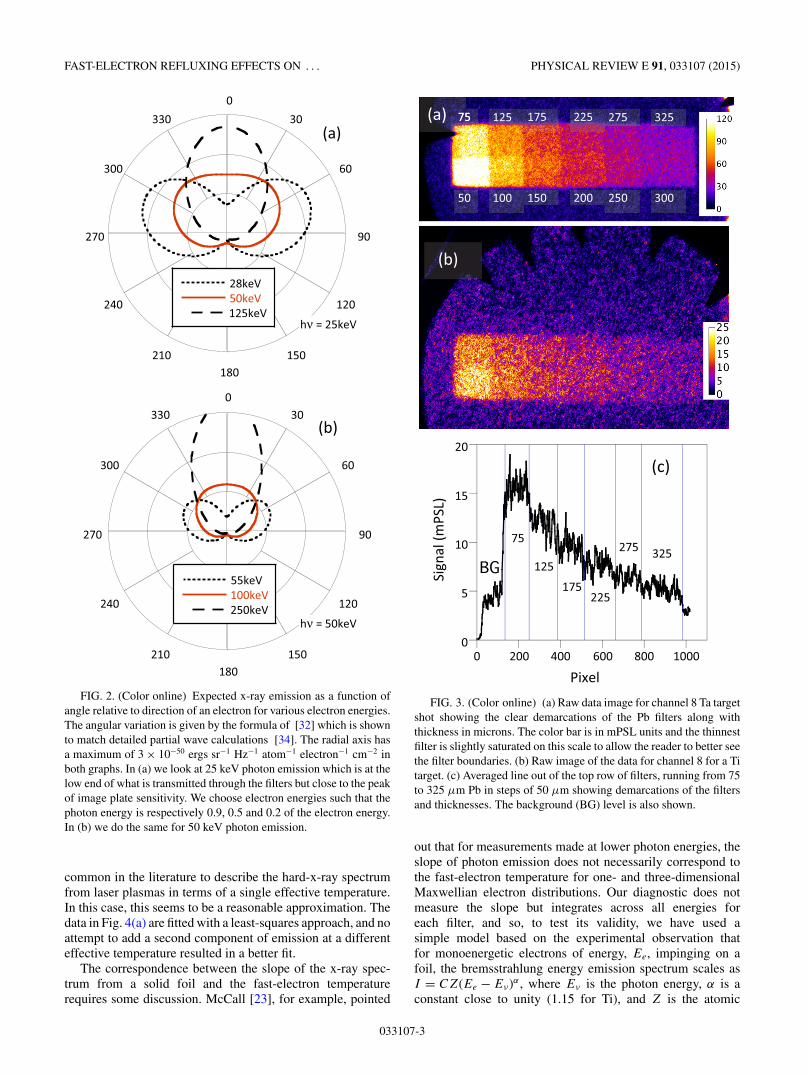
Before we discuss the results of our experiment, it may beof interest to see what level of anisotropy is expected in thebremsstrahlung x-ray signal. We expect, as seen below andfrom earlier work [22], to have fast-electron temperatures ofaround 60 keV. This is only a fraction of the mass energybut still leads to an electron speed of ∼0.45c. We can see inFig. 2 that we do indeed expect a strong anisotropy even whenconsidering the lowest energy of detected photons and typicalelectron energies.
In Fig. 3 we can see a typical raw image for detector 8placed 30◦ from the front normal of the target. We show datafrom a Ta target for comparison because the higher level ofemission allows us to more clearly see the filter boundaries,and this helps in the analysis. We did not use Ta generallyfor this work as this would introduce opacity effects for thethicker targets, which would complicate the analysis. We canalso see in Fig. 3 an averaged line out for one of the rows offilters, showing the signal uncorrected for background. We cansee that the image plates have a general background level ofa few mPSL that is fairly uniform and easily removed fromthe data. This background is only there when data are takenand so probably originates from fluorescence. A study of thefluorescence [26] using a modified detector design indicatedthat the background dropped with a filter-image plate distanceup to about 50 mm but it did not change beyond this, indicatingthat we minimized the background and that fluorescence fromthe chamber and detector body may be responsible.
In Fig. 4(a), we can see a typical comparison of abackground-subtracted signal through the filters with a predic-tion for a single effective Maxwellian fast-electron temperatureof 62 keV. The error bars in this figure simply represent thestandard deviation in the averaged line out, as seen in Fig. 3(b).Error bars in quantities such as angularly resolved emissionprofile and temperature, derived below, are calculated fromstatistical analysis of multiple shots. As noted above, it is
033107-2
FAST-ELECTRON REFLUXING EFFECTS ON . . . PHYSICAL REVIEW E 91, 033107 (2015)
ν
ν
FIG. 2. (Color online) Expected x-ray emission as a function ofangle relative to direction of an electron for various electron energies.The angular variation is given by the formula of [32] which is shownto match detailed partial wave calculations [34]. The radial axis hasa maximum of 3 × 10−50 ergs sr−1 Hz−1 atom−1 electron−1 cm−2 inboth graphs. In (a) we look at 25 keV photon emission which is at thelow end of what is transmitted through the filters but close to the peakof image plate sensitivity. We choose electron energies such that thephoton energy is respectively 0.9, 0.5 and 0.2 of the electron energy.In (b) we do the same for 50 keV photon emission.
common in the literature to describe the hard-x-ray spectrumfrom laser plasmas in terms of a single effective temperature.In this case, this seems to be a reasonable approximation. Thedata in Fig. 4(a) are fitted with a least-squares approach, and noattempt to add a second component of emission at a differenteffective temperature resulted in a better fit.
The correspondence between the slope of the x-ray spec-trum from a solid foil and the fast-electron temperaturerequires some discussion. McCall [23], for example, pointed
BG
FIG. 3. (Color online) (a) Raw data image for channel 8 Ta targetshot showing the clear demarcations of the Pb filters along withthickness in microns. The color bar is in mPSL units and the thinnestfilter is slightly saturated on this scale to allow the reader to better seethe filter boundaries. (b) Raw image of the data for channel 8 for a Titarget. (c) Averaged line out of the top row of filters, running from 75to 325 μm Pb in steps of 50 μm showing demarcations of the filtersand thicknesses. The background (BG) level is also shown.
out that for measurements made at lower photon energies, theslope of photon emission does not necessarily correspond tothe fast-electron temperature for one- and three-dimensionalMaxwellian electron distributions. Our diagnostic does notmeasure the slope but integrates across all energies foreach filter, and so, to test its validity, we have used asimple model based on the experimental observation thatfor monoenergetic electrons of energy, Ee, impinging on afoil, the bremsstrahlung energy emission spectrum scales asI = CZ(Ee − Eν)α , where Eν is the photon energy, α is aconstant close to unity (1.15 for Ti), and Z is the atomic
033107-3
K. MCKEEVER et al. PHYSICAL REVIEW E 91, 033107 (2015)
FIG. 4. (Color online) Sample data for 10 μm Ti foil viewedat 30◦ to front normal. The best fit is to 62 keV. (b) Fast-electrontemperature determined for epoxy-coated foils and shots on barefoils. The values are averages over several shots (typically three tofour) and the error bars show the standard error in the mean.
number of the foil material [23,27,28]. With this, we havepredicted the signal that would be detected through our filterarray for a given fast-electron distribution. By taking thispredicted spectrum and working back to estimate temperature,we have determined that, for a purely exponential electrondistribution (two-dimensional Maxwellian), the assumptionof an exponential spectrum in analyzing the bremsstrahlungreproduces the assumed hot-electron temperature accurately.However, if the fast-electron distribution is one-dimensional,then there is a systematic underestimate of temperatureby up to 20% at the highest values and an overestimateof similar magnitude if the electron distribution was fullythree-dimensional. The analysis presented here assumes atwo-dimensional Maxwellian.
In Fig. 4(b), we see the effective temperature determinedat the full range of angles for both epoxy-coated and uncoatedfoils. For the epoxy-coated data, we have included therelatively small effect of absorption in the 1 mm epoxy layer,assuming the fast electrons do not penetrate far into theepoxy. As stated above, earlier work [22], with similar laserand target parameters, indicated that resonance absorptionwas the principal absorption mechanism. The temperaturecould be represented by the model of Wilks and Kruer,
T h (keV) ≈ 10[TcI15λ2]1/3 [29], where Tc is the background
electron temperature in keV, I15 is the intensity in units of1015 W cm−2, and λ is the wavelength in μm. Using thisscaling and the data in Fig. 4, we estimate Tc = 100 eV forthe present run. For comparison, HYADES [30] simulation ofthe prepulses indicated a preformed plasma with density scalelength 2.4 μm and temperature 50 eV at critical density priorto the main pulse interaction.
The averaged temperature from several shots for both typesof target foil is shown in Fig. 4(b). For the epoxy-coated case,there is evidence that the inferred emission temperature issystematically lower than for uncoated foils when we looktoward the front normal (from 270◦ round to 90◦ in Fig. 4 orfrom detectors 14 CW round to 9 in Fig. 1). This can be relatedto the lack of refluxing of fast electrons and their anisotropyin hard-x-ray emission. As noted, we have attempted to fit thedata from the detectors to a bi-Maxwellian distribution, but wehave failed to find fits that are better than a single Maxwellian.We should note that this does not mean there is only onetemperature of electrons. In addition to the bremsstrahlungfrom fast electrons penetrating the solid foil, there should bea so called “thermal” background emission coming from theplasma created on the laser-irradiated side. However, our Pbfilters means that the detection system is effectively insensitiveto x rays of energy below 25 keV, and this source of emissioncontributes little to the signal.
In Fig. 5(a), we can see a plot of the signal level on theimage plate detected through the 50 μm Pb filter layer forboth 10-μm-thick bare foils and 10-μm foils coated in epoxy.The data are in terms of a raw signal on the image plate,but a slight normalization was applied to account for laserenergy variations, although no shot was more than 6% fromthe average. Since the lead filter effectively cuts out emissionbelow 25 keV, absorption in the epoxy has a minimal effect onsignal.
In Fig. 5(a) there is a wide but distinct peak in the rearnormal direction for the case of epoxy-coated targets, whereasthe bare foil case is significantly more isotropic. The ratioof the signal to the rear and front target normal directionsis ∼3.4 for the epoxy-coated case. In addition, the overallemission is lower in the case of epoxy-coated targets for alldirections. The data for 10 μm epoxy-coated foils but takenthrough thicker Pb filters all the way to 300 μm show a similarpeak at the rear normal, although the ratio of the signal betweenthe rear and front normal directions increases to nearly 5, asmight be expected for a detection channel that samples higher-energy photons coming from the most energetic electrons.The solid line in Fig. 5(a) is a calculation made using theangular variation formulated originally by Kirkpatrick andWiedmann [31,32], which has been shown to agree very wellwith tabulated partial wave calculations [28,33]. We haveaveraged it over a beam of electrons with energy distributiongiven by f (E) = A exp(−E/Th), where Th = 50 keV is aneffective fast-electron temperature, based on the analysispresented above. Spectral summation was carried out over allphoton energies (out to Eph = 10Th) using the bremsstrahlungspectrum approximation discussed above [23,27,28], which isfolded with the exponential electron distribution to give aneffectively time-integrated spectrum. The transmission for a50 μm lead filter [34,35] and the image plate response [24,25]
033107-4
FAST-ELECTRON REFLUXING EFFECTS ON . . . PHYSICAL REVIEW E 91, 033107 (2015)
(a)
FIG. 5. (a) Signals through the 50 μm Pb filters for 10-μm-thickbare and epoxy-coated foils. The solid line is a prediction ofthe angular dependence for a collimated beam of electrons at atemperature of 50 keV based on the angular dependence given byKirkpatrick and Wiedmannn [31]. The dotted and dashed lines includebroadening due to electron divergence as described in the text for barefoils and epoxy-coated foils, respectively. (b) Similar data for 50 μmTi with and without epoxy.
as a function of photon energy have both been folded in. Thedashed and dotted lines are calculated by taking the angularemission model for a beam of electrons and folding with theelectron divergence, as discussed next.
We have simulated our experiment using the ZEPHYROS
3D macroparticle hybrid simulation code [36,37]. This codeinjects an exponential distribution of fast electrons with afixed effective temperature in a square pulse into a solidtarget. A resistivity model for Ti and a scattering model forfast electrons help to calculate the evolution of the current,magnetic and electric fields, and electron trajectories. We haveused the code to track the momentum of each electron in thesimulation. In doing so, we were able to generate temporalsnapshots of the momentum direction of each macroparticle.With a postprocessor we were able to calculate the energyand direction with respect to each detector in the horizontalplane. We then used the spectral emission profile given by acorrected Bethe-Heitler approximation, again shown by Salvatet al. to be a good approximation to tabulated partial wave
calculations [28,33]. By folding this with the normalizedangular distribution of x rays calculated from Kirkpatrick-Wiedmann [31,38], we were able to predict the emissionas a function of angle. By averaging over snapshots every200 fs until the fast electrons decay (2 ps), we generated atime-integrated prediction. Our results for 10 μm foils canbe seen in Fig. 5(a). The best results were found for aninitial electron divergence full angle of 50◦. As we can see,for the epoxy-coated targets there is a very good fit. This isnot surprising, as a similar divergence was found in earlierwork with the same laser under similar conditions [22]. Inthis respect, our hard-x-ray data that relate to the direction offast-electron flow are complementary to and consistent withthe K-α data in [22] that relate to the spatial location offast-electron flow. Our inferred divergence is also consistentwith the recent simulations of Ovchinnikov et al. [39], whichwere made for laser pulses of the same wavelength and asimilar duration to ours. For the bare foils, the predictedemission is more isotropic, as seen in the experimental data.The simulation, however, does show slight dips centeredaround 90◦ and 270◦, which are the directions along thetarget surface. This is likely to be due to the simulation,which does not include target hydrodynamics, assuming amirrorlike reflection of electrons from the rear surface ofthe foil. Nevertheless, the overall agreement between whatis expected experimentally for the two cases and what ispredicted is good and clearly illustrates the connection betweenthe anisotropy and refluxing.
In Fig. 5(b), we see similar data but taken for 50 μmTi foils. In this case, we see anisotropy in both cases anda peak emission that is slightly higher than for the 10 μmfoil cases. This can be explained relatively simply. For atypical electron temperature of 50 keV, the range of an averageenergy electron is 30 μm in Ti. This means that in the 10 μmfoils, the electrons reach the rear of the foil and reflux, thusenhancing the bremsstrahlung emission over the epoxy case,and also, since they change direction, it causes a more isotropicemission. For the 50 μm foil, most electrons do not reach therear of the foil, and so without refluxing the anisotropy issimilar to the epoxy-coated case. For the thicker Ti foils, wemight expect scattering to lessen the anisotropy, and indeedwe can see that the ratio of the rear normal to the front normalsignal drops to 2.4 for the 50 μm foils. However, we can seethat the simulated distribution determined with ZEPHYROS inthe same way as for the 10 μm case seems to fit quite well.Any additional scattering within the foil is clearly not enoughto remove the anisotropy in the x-ray emission totally.
It is of interest to see the effect of refluxing on otherparameters within the ZEPHYROS simulations presented above.In Fig. 6, we can see the fast-electron density mapped. Thesimulations use an nx = 40, ny = 125, nz = 125 grid, wherex is the direction of propagation through the foil, left to right.The foil thickness is 10 μm. The divergence was set to 50degrees full angle as for the simulations above. As in previouswork [22] with the same laser where the K-α source size wasdetermined to be a minimum of 70 μm, we have set the effec-tive spot size to this value to account for the spreading of fastelectrons out from the focal spot region before entering the foil.
The effect of refluxing in enhancing the fast electrons withinthe Ti foil is clear to see in Fig. 6, where there is roughly a
033107-5
K. MCKEEVER et al. PHYSICAL REVIEW E 91, 033107 (2015)
FIG. 6. (Color online) Fast-electron density for simulated 50 keVeffective electron temperature in Zephyros (a) without refluxing and(b) with refluxing. The data are taken in a snapshot at 0.8 ps, whichis just at the end of the pulse in the simulation. In (b) the solid lineshows a line out from the center of the foil indicating roughly 20%variations in electron density.
doubling of fast-electron density. For the refluxing case, we cansee that there is also enhanced evidence of some filamentationin the fast-electron density with variations of about 20%across the electron beam. In Fig. 7, we see a clear differenceagain between the cases in which we consider the magneticfield. The small saturated regions in the refluxing case have
FIG. 7. (Color online) The z component of the magnetic field atthe center plane of the target for the same conditions as Fig. 6 (a)without refluxing and (b) with refluxing.
magnetic fields reaching 1300 T, while in the nonrefluxingcase they reach 800 T. The main difference, however, is inthe strong appearance of interlacing “fingers” of magneticfields in opposite directions. This is due to the interactionof two opposing streams of fast electrons. We expect in thenonrefluxing case that a Weibel-type instability can form dueto the interaction of the fast electrons and the induced returncurrent. The electrons reflected from the rear of the foil interactwith the “incoming” fast electrons to enhance this in therefluxing case. The use of polarimetric reflection techniquesto measure the magnetic field on the rear of laser-irradiatedfoils has been discussed by Chatterjee et al. [40], and thiscould in principle be applied to the bare foil case. However,experimental comparison of bare to coated foils in this casewould require a rear surface layer that would allow the probe topass unhindered but also absorb all the fast electrons reachingthe rear of the foil. This would be a significant technicalchallenge.
In Fig. 8 we can see the background temperature in thesimulation. We can see a clear difference in the two cases,with enhanced fingers of higher temperature in the refluxingcase linked to the high fast-electron density regions caused bythe instability in the magnetic field.
Anisotropic x-ray emission has been seen to occur be-fore [19,20], but it has generally been seen to occur athigher irradiance with electron temperatures in the stronglyrelativistic regime. In our case, the temperatures are somewhatlower but still relativistic (β > 0.5). Furthermore, in [19,20],the peak in hard-x-ray emission is seen in the direction closerto specular reflection of the incident laser pulse. This has beenconnected to acceleration of electrons in the direction of thereflected pulse via the J×B mechanism, which is relevant at thehigher intensities used. In other previous work [41] with muchhigher intensities and a more limited number of detectors, the
FIG. 8. (Color online) Background temperature at the centerplane of the target for the same conditions as Fig. 6 (a) withoutrefluxing and (b) with refluxing.
033107-6
FAST-ELECTRON REFLUXING EFFECTS ON . . . PHYSICAL REVIEW E 91, 033107 (2015)
hard-x-ray yield was seen to peak in a direction normal tothe target rear, although no measurements were made fromthe front, laser-irradiated side. In that work, a top modest Z
layer (Al) covered the main Ag target, polystyrene was usedto limit refluxing, and comparison was not made without thepolystyrene. Work by Norreys et al. [42] showed a peak in>10 MeV γ rays that is between the target rear normal andthe direction of the laser propagation. Again, measurementsto the rear of the target only are presented, and in that casethe mechanism for absorption of the laser energy to generatethe required electron energies is likely to be quite differentfrom our case. Finally, we note the paper by Li et al. [43],in which the fast electrons ejected from a target are detected.In that paper, the irradiance is similar to that used by us, butthe pulse duration is much shorter (30 fs). At 45◦ incidenceon target they see electrons above 300 keV predominatelyejected normal to the target surface but with some evidenceof electrons pushed along the target surface, a feature thatbecomes dominant at a higher angle of incidence (70◦). Incomparing this to the present work, it is worth noting thatLi et al. detect only the higher-energy electrons that escapethe target while our x-ray measurements are produced by thebulk of fast electrons within the target. It is possible that inour work, a small high-energy tail of electrons could exist,created by, for example, J×B heating, and that measurementof escaping fast electrons would show this. However, the x-rayemission is, from our data, evidently dominated by a moremodest temperature (∼60 keV) population that is likely to becontained with the target.
In summary, we have made several key observations in ourexperiment. First, we have observed anisotropy in hard-x-rayemission at lower intensities than in previous work, at thelower limit of the relativistic regime with fast electrons below100 keV average energy. This may initially seem surprising
but is less so when we consider that these electrons are stilltraveling at around half light speed, and relativistic transfor-mation of the emission cross section is considerable, as seen inFig. 2.
Secondly, the peak emission is directly in the directionnormal to the rear of the target. This is due to resonanceabsorption being the dominant electron heating mechanism,which means that electron acceleration is primarily alongthe density gradient normal to the target. This is entirelyconsistent with operating in the weakly relativistic regimewhere mechanisms such as J×B acceleration are not yetdominant. In modeling the x-ray emission angular profile,we have derived a value for the electron beam divergencethat is in good agreement with predictions [39] and previousmeasurements [22] made with a different technique but undersimilar conditions.
Next, the measured effective temperature of the fastelectrons has been shown to be more isotropic than the x-rayemission intensity. This is consistent with the observationthat a single Maxwellian approximation fits the data betterthan a two-temperature approximation. Finally, we have madeobservations directly linking angular distribution of hard-x-rayemission from intense laser-plasma interactions with electronrefluxing. We have, in fact, been able to switch the anisotropyon and off. The significance of this work is that electrondynamics can be revealed through hard-x-ray emission andunderstanding this is key to understanding and developingapplications of intense laser-solid interactions such as particlebeam generation.
This work was supported by the UK Engineeringand Physical Sciences Research Council (Grants No.EP/C003586/1, No. EP/G007462/01, No. EP/I029206/1, andNo. EP/L013975/1).
[1] W. L. Kruer, The Physics of Laser Plasma Interactions(Westview, Boulder, CO, 2003).
[2] A. Rousse, P. Audebert, J. P. Geindre, F. Fallies, J. C. Gauthier,A. Mysyrowicz, G. Grillon, and A. Antonetti, Phys. Rev. E 50,2200 (1994).
[3] C. Reich, P. Gibbon, I. Uschmann, and E. Forster, Phys. Rev.Lett. 84, 4846 (2000).
[4] D. C. Eder, G. Pretzler, E. Fill, K. Eidmann, and A. Saemann,Appl. Phys. B 70, 211 (2000).
[5] K. B. Wharton et al., Phys. Rev. Lett. 81, 822 (1998).[6] T. Feurer et al., Phys. Rev. E 65, 016412 (2001).[7] J. D. Kmetec, C. L. Gordon, J. J. Macklin, B. E. Lemoff,
G. S. Brown, and S. E. Harris, Phys. Rev. Lett. 68, 1527(1992).
[8] M. Borghesi, J. Fuch, S. V. Bulanov, A. J. Mackinnon,P. K. Patel, and M. Roth, Fusion Sci. Technol. 49, 412(2006).
[9] S. Fourmaux, C. Serbanescu, R. E. Kincaid, Jr., A. Krol, andJ. C. Kieffer, Appl. Phys. B 94, 569 (2009).
[10] H. S. Park et al., Phys. Plasmas 13, 056309 (2006).[11] M. Nishikino et al., Rev. Sci. Instrum. 81, 026107 (2010).[12] S Chen et al., Phys. Plasmas 14, 102701 (2007).
[13] J. Myatt, W. Theobald, J. A. Delettrez, C. Stoeckl, M. Storm,T. C. Sangster, A. V. Maximov, and R. W. Short, Phys. Plasmas14, 056301 (2007).
[14] M. N. Quinn, X. H. Yuan, X. X. Lin, D. C. Carroll, O. Tresca,R. J. Gray, M. Coury, C. Li, Y. T. Li, C. M. Brenner, A. P. L.Robinson, D. Neely, B. Zielbauer, B. Aurand, J. Fils, T. Kuehl,and P. McKenna, Plasma Phys. Controlled Fusion 53, 025007(2011).
[15] V. T. Tikhonchuk, Phys. Plasmas 9, 1416 (2002).[16] P. Neuymayer et al., Phys. Plasmas 17, 103103 (2010).[17] G. Nersisyan et al., Phys. Rev. E 85, 056415 (2012).[18] S. Buffechoux et al., Phys. Rev. Lett. 105, 015005 (2010).[19] F. Zamponi et al., Phys. Rev. Lett. 105, 085001 (2010).[20] S. Dusterer et al., Contrib. Plasma Phys. 41, 171 (2001).[21] T. Dzelzainis et al., Laser Particle Beams 28, 451 (2010).[22] M. Makita et al., Phys. Plasmas 21, 023113 (2014).[23] G. H. McCall, J. Appl. Phys. 15, 823 (1982).[24] T. Doppner et al., Rev. Sci. Instrum. 83, 10E508 (2012).[25] A. L. Meadowcroft, C. D. Bentley, and E. N. Stott, Rev. Sci.
Instrum. 79, 113102 (2008).[26] K. J. A. McKeever, Ph.D. thesis for Queen’s University of
K. MCKEEVER et al. PHYSICAL REVIEW E 91, 033107 (2015)
[27] E. Storm, Phys. Rev. A 5, 2328 (1972).[28] F. Salvat, J. M. Fernandez-Varea, J. Sempau, and X. Llovet,
Radiat. Phys. Chem. 75, 1201 (2006).[29] S. C. Wilks and W. L. Kruer, IEEE J. Quantum Electron. 33,
1954 (1997).[30] J. T. Larsen and S. M. Lane, J. Quantum Spectrosc. Radiat.
Transf. 51, 179 (1994).[31] P. Kirkpatrick and L. Wiedmann, Phys. Rev. 67, 321 (1945).[32] Z. J. Ding, R. Shimizu, and K. Obori, J. Appl. Phys. 76, 7180
(1994).[33] L. Kissel, C. A. Quarles, and R. H. Pratt, At. Data Nucl. Data
Tables 28, 381 (1983).[34] NIST Standard Reference Database 126: S. M. Seltzer, Radiat.
Res. 136, 147 (1993).
[35] NIST Standard Reference Database 126: Int. J. Appl. Radiat.Isotopes 33, 1269 (1982).
[36] S. Kar, A. P. L. Robinson, D. C. Carroll, O. Lundh, K. Markey,P. McKenna, P. Norreys, and M. Zepf, Phys. Rev. Lett. 102,055001 (2009).
[37] A. P. L. Robinson, M. H. Key, and M. Tabak, Phys. Rev. Lett.108, 125004 (2012).
[38] E. Acosta, X. Llovet, E. Coleoni, J. A. Riveros, and F. Salvat,J. Appl. Phys. 83, 6038 (1998).
[39] V. M. Ovchinnikov et al., Phys. Rev. Lett. 110, 065007 (2013).[40] G. Chatterjee et al., Phys. Rev. Lett. 108, 235005 (2012).[41] C. D. Chen et al., Phys. Plasmas 20, 052703 (2013).[42] P. Norreys et al., Phys. Plasmas 6, 2150 (1999).[43] Y. T. Li et al., Phys. Rev. Lett. 96, 165003 (2006).