Coke Drum Reliability Workshop Fast quench problems and how they damage coke drums Rio De Janeiro, Brazil • August 7, 2009 Rio De Janeiro, Brazil August 7, 2009 Presented by: Julian Bedoya [email protected]Prepared by: Richard Boswell [email protected]
Transcript
Coke Drum Reliability Workshop
Fast quench problems and how they
y p
damage coke drums Rio De Janeiro, Brazil • August 7, 2009Rio De Janeiro, Brazil August 7, 2009
• Permanent deformation pattern of vessels in cyclicvessels in cyclic service
• Skirt is attached to the cylinder by welding
2
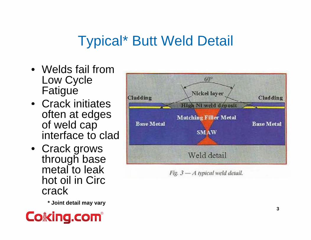
Typical* Butt Weld DetailTypical Butt Weld Detail
• Welds fail from Low Cycle Fatigue
• Crack initiatesCrack initiates often at edges of weld cap interface to cladinterface to clad
• Crack grows through base
l l kmetal to leak hot oil in Circ crack
3* Joint detail may vary
Some Key Points of the Coking Cyclethe Coking Cycle
• The drum grows larger and taller when it is hot
• It is filled with a lot of hard material as the• It is filled with a lot of hard material as the hydrocarbon cracks and releases vapor
• Some cokes will bond to the wall, and flow channels develop within the coke bedchannels develop within the coke bed
• Hot oil is stopped (diverted to other drum)
• Steam is used to remove volatile vapor
• Water enters from bottom to cool the coke bed, becomes steam and flows up the center or outside along the walls ?
• The coke drum shrinks in diameter and height as it cools
• Eventually water can form and fills the drum
4
Eventually water can form and fills the drum
• Which way does the water go?
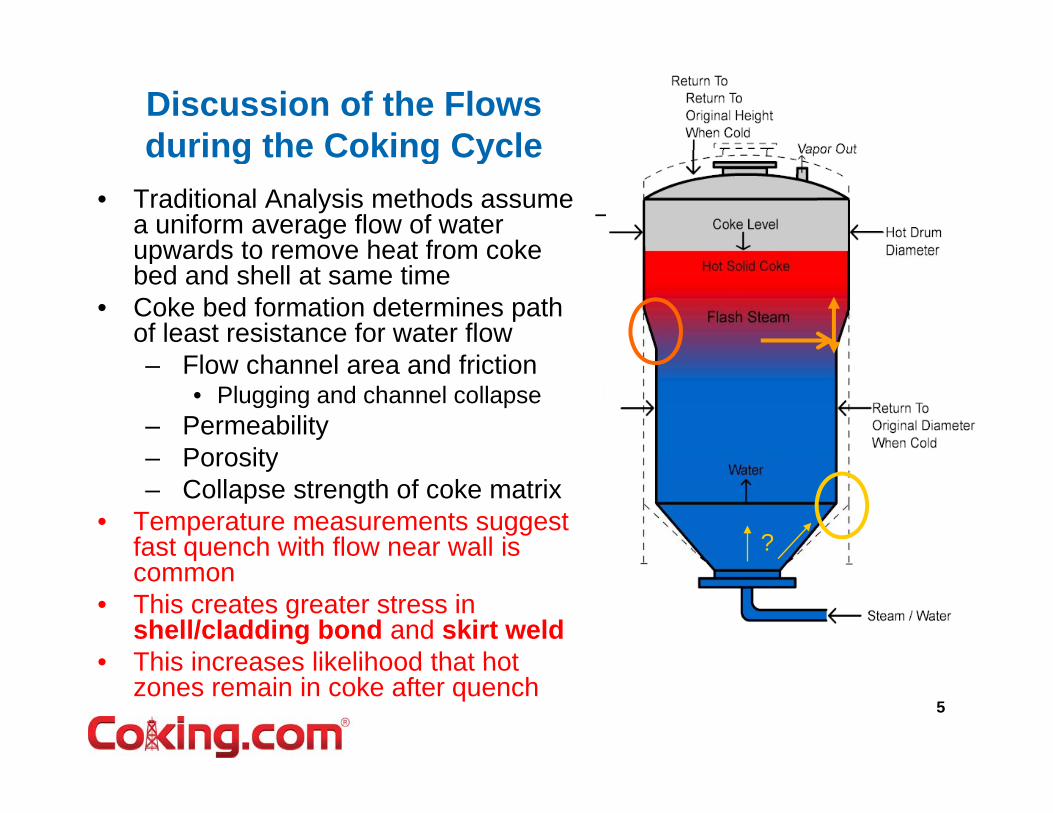
Discussion of the Flows during the Coking Cycleduring the Coking Cycle
• Traditional Analysis methods assume a uniform average flow of water upwards to remove heat from cokeupwards to remove heat from coke bed and shell at same time
• Coke bed formation determines path of least resistance for water flow
Fl h l d f i ti– Flow channel area and friction• Plugging and channel collapse
– PermeabilityPorosity
?
– Porosity– Collapse strength of coke matrix
• Temperature measurements suggest fast quench with flow near wall is qcommon
• This creates greater stress in shell/cladding bond and skirt weld
• This increases likelihood that hot5
• This increases likelihood that hot zones remain in coke after quench
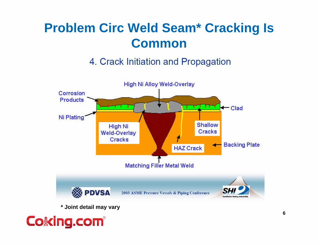
Problem Circ Weld Seam* Cracking Is CommonCommon
6* Joint detail may vary
Cracking from ID at Weld Cap to Clad J tiJunction
7
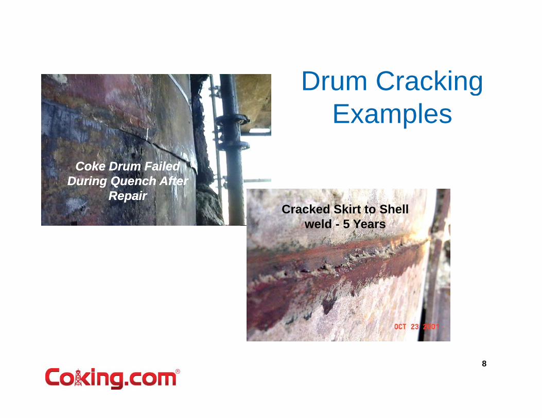
Drum CrackingDrum Cracking Examples
Coke Drum Failed Coke Drum Failed During Quench AfterDuring Quench AfterDuring Quench After During Quench After
RepairRepairCracked Skirt to Shell
weld - 5 Years
8
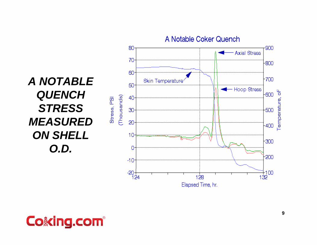
A NOTABLE QUENCH STRESSSTRESS
MEASURED ON SHELLON SHELL
O.D.
9
A Measured Cycle For In-Line Skirt Stress Response (OD)
Temperature
Axial Stress
Hoop Stress
10
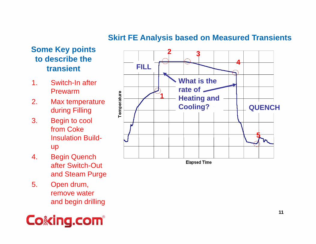
Skirt FE Analysis based on Measured Transients
FILL
2 34
Some Key points to describe the
transientWhat is the rate of Heating and Cooling? QUENCH
1
1. Switch-In after Prewarm
2. Max temperature Cooling? QUENCH
5
during Filling3. Begin to cool
from Coke Insulation Build 5Insulation Build-up
4. Begin Quench after Switch-Out and Steam Purge
5. Open drum, remove water
d b i d illi11
and begin drilling
CCone
Skirt
Cone Peak Thermal Rate
12
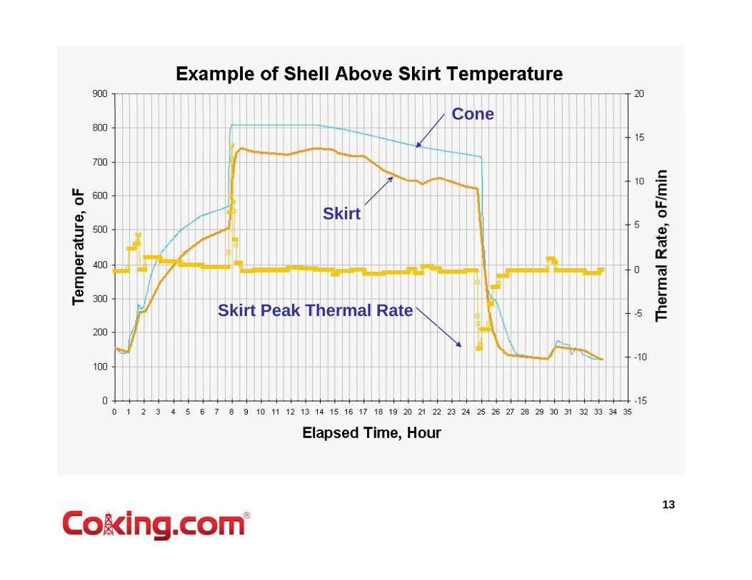
CCone
Skirt
Skirt Peak Thermal Rate
13
During Quench - Skirt is Pushed and then gets Pulled by Knuckle
DISPLACED SHAPE AT THE END OF FILL
then gets Pulled by Knuckle
DISPLACED SHAPE 1 HOUR INTODISPLACED SHAPE 1 HOUR INTO QUENCH
( MAXIMUM STRESS DURING QUENCH OCCURS HERE)
14
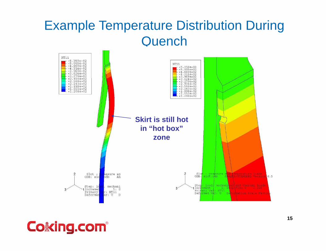
Example Temperature Distribution During Quench
Skirt is still hot in “hot box”
zone
15
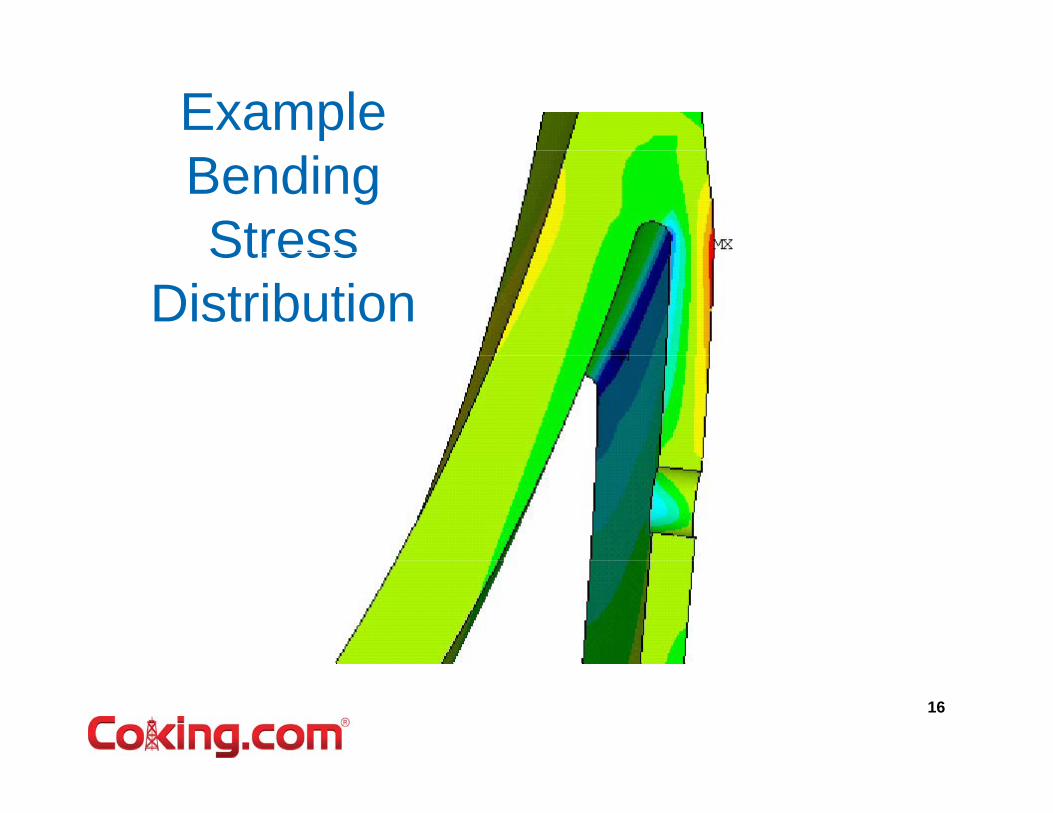
Example Bending StressStress
Distribution
16
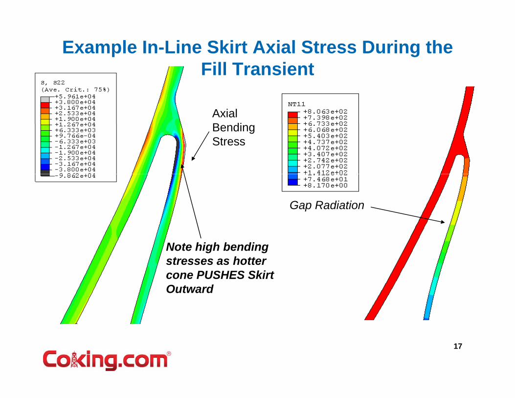
Example In-Line Skirt Axial Stress During the Fill TransientFill Transient
Axial B diBending Stress
Gap Radiation
Note high bending stresses as hotter cone PUSHES Skirtcone PUSHES Skirt Outward
17
Example Tangent Mount Axial Stress During the Quench Transient
Axial Bending Stress
Gap Radiation,Gap Radiation,
Gap Conductance active when inactive when in contact
Note high bending g gstresses as cooler cone PULLS Skirt Inward
18
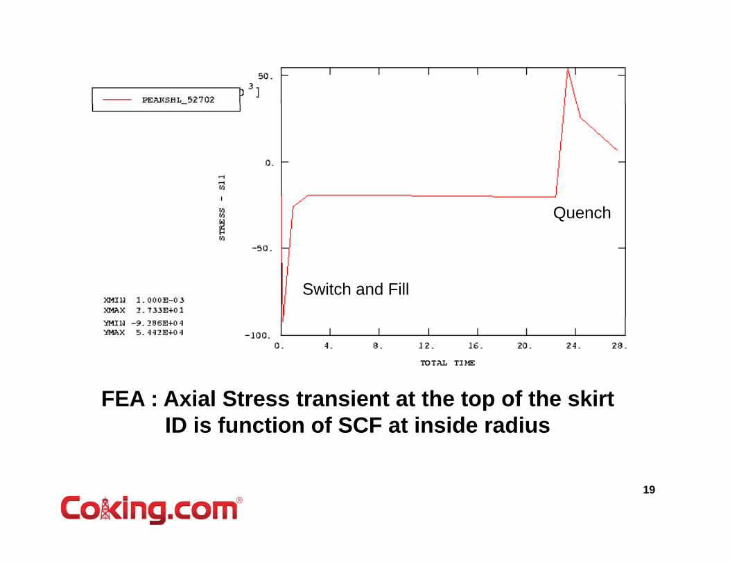
Quench
Switch and Fill
FEA : Axial Stress transient at the top of the skirt ID is function of SCF at inside radius
19
FATIGUE LIFE CALCULATION FOR A SKIRT IS MORE ACCURATE USING MEASURED THERMAL TRANSIENT
•Design (by others) predicted 152
Finite Element Model vs Reality
152 years
•SES Transient analysis performed prior to T/A
•Maximum stress intensity range during transient = 143 430 psi143,430 psi
• Using ASME code Section VIII Division 2 fatigue design Table 5 110 1 UTS < 80 ksi
After 5 years (~1369 cycles) Table 5-110.1, UTS < 80 ksi, a fatigue life of 1228 cycles was obtained.
y ( y )cracks were discovered in all 4 drum skirts (no slots) prior to T/A
20
to T/A
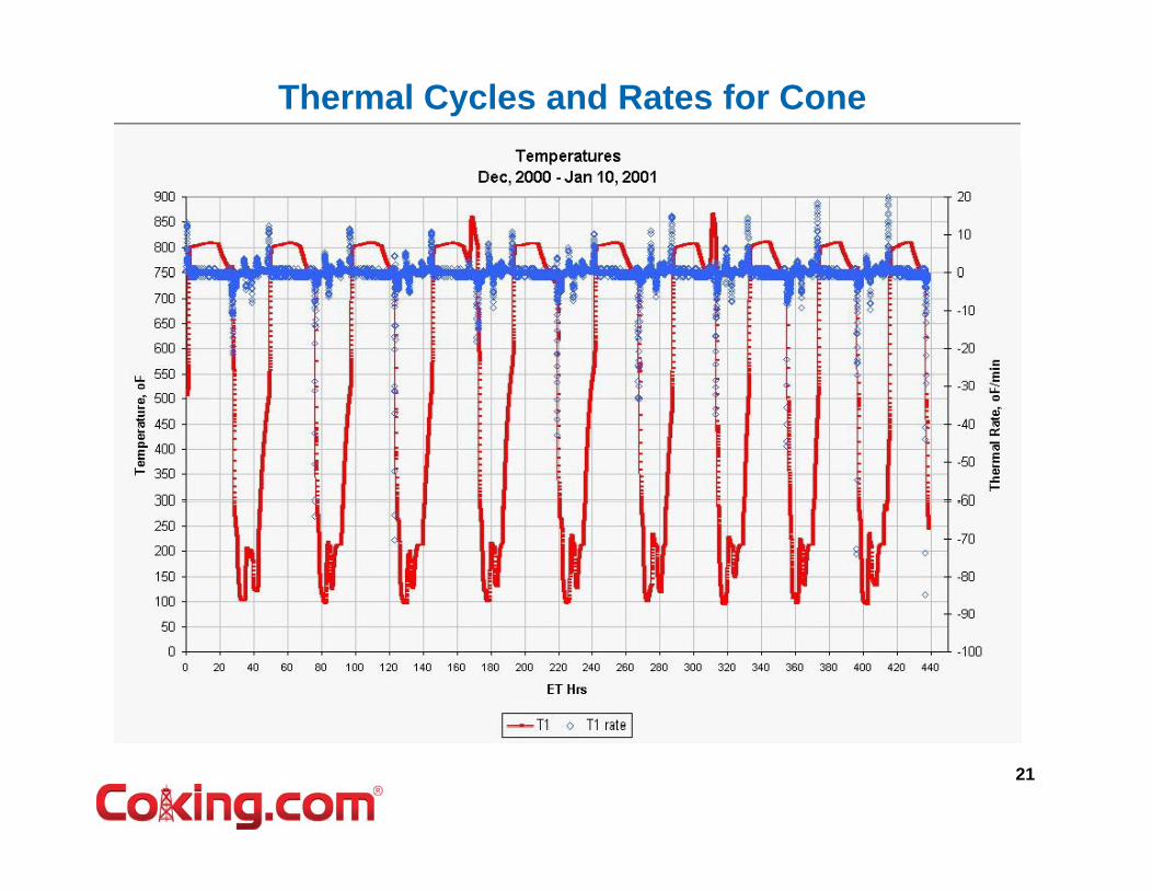
Thermal Cycles and Rates for Cone
21
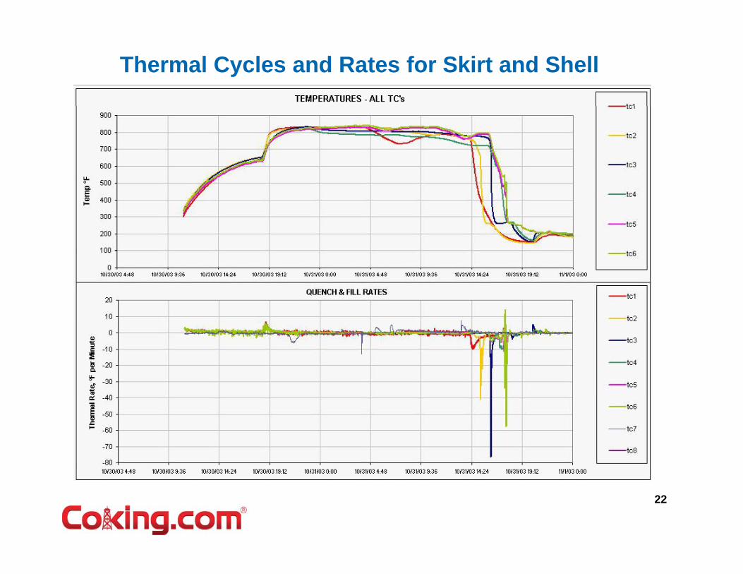
Thermal Cycles and Rates for Skirt and Shell
22
Thermal Cycles and Rates for Skirt and Shell
23
Thermal Quench and Rates for Skirt and Shell
ShellSkirt
S e
24
Thermal Rate Histogram for Shell
2003
2004
25
Does Fast Quench Shorten Cyclic Lif ?Life ?
• Where Does Fast Quench Hurt?Where Does Fast Quench Hurt?– Skirt Attachment Weld– Shell Circ SeamsShell Circ Seams– Cone Circ Seams
• Why Does Fast Quench Hurt?Why Does Fast Quench Hurt?– Constraint created by components at different
temperatures (i.e. thermal expansions)– Different Material Properties (Yield,
Expansion, Conductivity, Diffusivity)
26
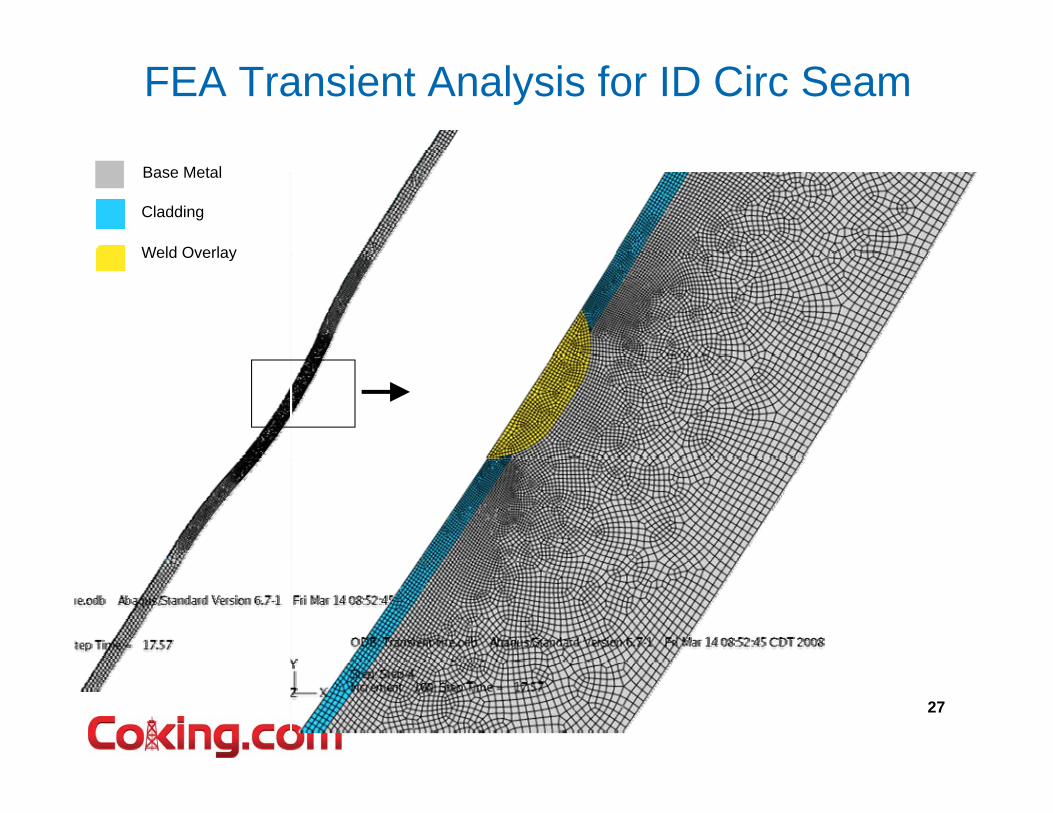
FEA Transient Analysis for ID Circ Seam
Base Metal
Cladding
Weld OverlayWeld Overlay
27
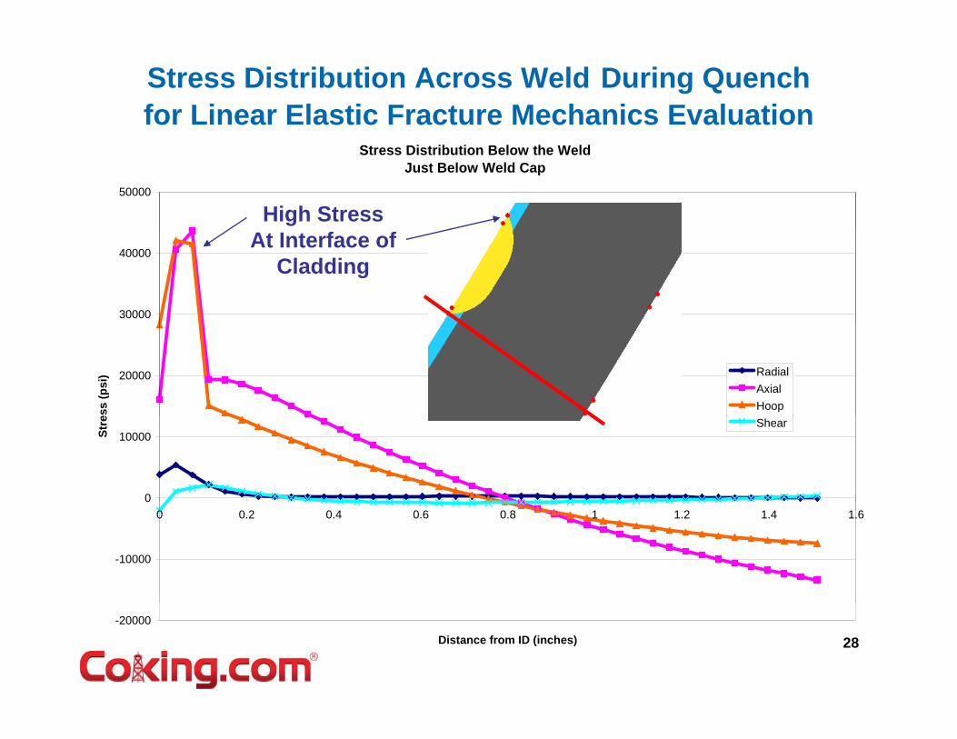
Stress Distribution Across Weld During Quenchfor Linear Elastic Fracture Mechanics Evaluation
Stress Distribution Below the WeldJust Below Weld Cap
50000
High Stress
30000
40000At Interface of
Cladding
20000
ess
(psi
) RadialAxialHoop
0
10000Stre Shear
-10000
0 0.2 0.4 0.6 0.8 1 1.2 1.4 1.6
28-20000
Distance from ID (inches)
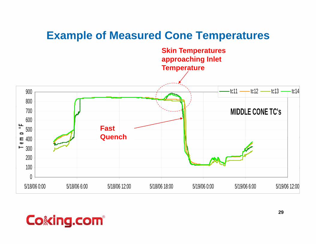
Example of Measured Cone TemperaturesSkin Temperatures approaching Inlet Temperature
Fast Quench IssuesT diti l A l i th d if fl f• Traditional Analysis methods assume a uniform average flow of water upwards to remove heat from coke bed and shell at same time, or up thru central primary flow channel.
• Coke bed formation determines path of least resistance for water pflow– Flow channel area and friction
• Plugging and channel collapse creates new flow pathsPermeability– Permeability
– Porosity– Collapse strength of coke matrix
• Temperature measurements suggest fast quench with flow near wallTemperature measurements suggest fast quench with flow near wall is common– Generally random and not necessarily aligned with Inlet Nozzle
Thi t t t i h ll/ l ddi b d d ki t ld• This creates greater stress in shell/cladding bond and skirt weld– Creates greater stress at circ seams tri-metal junction
• This increases likelihood that hot zones remain in coke bed after
30
This increases likelihood that hot zones remain in coke bed after quench
What to do about Fast Quench ?What to do about Fast Quench ?• Change the way you do it• Use Sensor Measurements (TC and
HTSG) to guide you) g y• Use your Process Technology experts to
address the possible procedures andaddress the possible procedures and maintain production
• Change the way drums are made• Change the way drums are made• Or, be prepared for continued problems….