20
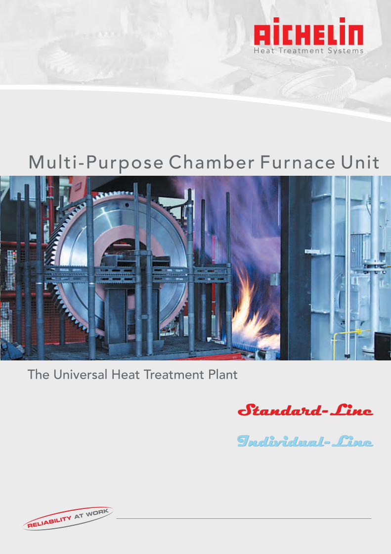
Individual-Line Individual-Line Individual-Line Standard-Line Standard-Line Standard-Line The Universal Heat Treatment Plant Multi-Purpose Chamber Furnace Unit
| Date post: | 24-Dec-2015 |
| Category: |
Documents |
| Upload: | sathiyaprakash |
| View: | 479 times |
| Download: | 43 times |
Individual-LineIndividual-LineIndividual-Line
Standard-LineStandard-LineStandard-Line
TI02-01/Mrz2010/E
The Universal Heat Treatment PlantThe Universal Heat Treatment Plant
http://www.aichelin.com
Subject to technical changes® ® ® ® ®AICHELIN , NOXMAT , NITROC , ENDOMAT , FLEXICLEAN
are registered trademarks
AICHELIN Ges.m.b.H.Postfach 210A-2340 MödlingPhone (+43) (2236) 236 46 - 0Telefax (+43) (2236) 22 22 [email protected]
AICHELIN Service GmbHPostfach 340D-71603 LudwigsburgPhone (+49) (7141) 6437 - 0Telefax (+49) (7141) 6437 - [email protected]
NOXMAT GmbHRingstraße 7D-09569 OederanPhone (+49) (37292) 65 03-0Telefax (+49) (37292) 65 [email protected]
EMA Indutec GmbHPetersbergstrasse 9D-74909 MeckesheimPhone (+49) (6226) 788 - 0Telefax (+49) (6226) 788 - [email protected]
AICHELIN Heat Treatment Systems (Beijing) Co. Ltd.10 00 86 Beijing, ChinaPhone (+86) (10) 8255 1421Telefax (+86) (10) 8255 [email protected]
SAFED SUISSE SA36, rue Emile-BoéchatCH - 2800 DelémontPhone (+41) (32) 421 44 60Telefax (+41) (32) 421 44 [email protected]
Multi-Purpose Chamber Furnace UnitMulti-Purpose Chamber Furnace Unit
2 19
When are Chamber Furnaces preferentially used?
for small and middle capacities
for different heat treatment procedures
for different kind of parts and high diversity of parts
at charge weights of appr. 150 - 1800 kg (even more in special cases)
if flexibility is required
for different production requirements
if quality with economy is required
!
!
!
!
!
!
!
1. IntroductionDuring the last decades, AICHELIN Group has built far more than 1000 protective gas chamber furnaces and put them into operation. Most of these plants provide their service reliably this very day. This impressively proves the permanent high quality, reliability and economy of these plants. Due to the central meaning of this furnace type, it is being permanently developed and constantly held together with our customers on the highest state of the art. This has now resulted in the creation of three series, where each of them is optimally aligned to your needs. :
The low cost series with superior components. Further description within this folder.
Powerful and worth every Cent. If the standard line does not meet your requirements at 100%. Also described here
The series, that fits into EVERY existing chamber furnace plant. Description see separate folder.
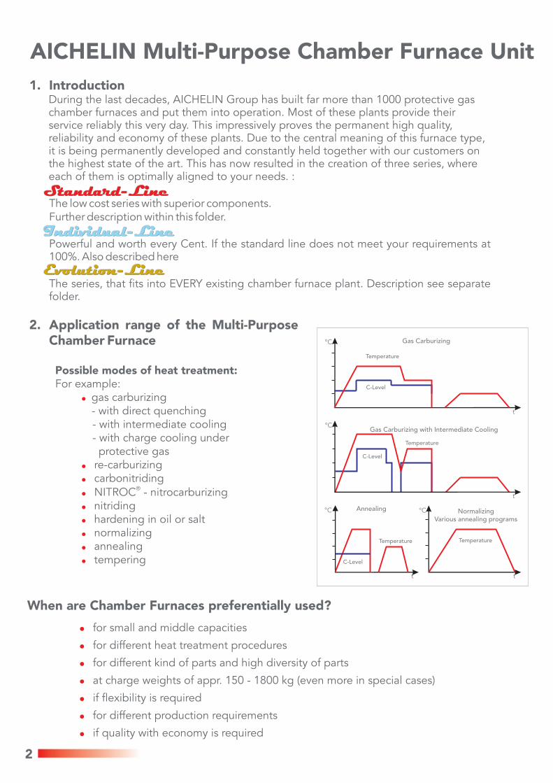
2. Application range of the Multi-Purpose Chamber Furnace
Possible modes of heat treatment:For example:
gas carburizing - with direct quenching
- with intermediate cooling- with charge cooling under protective gasre-carburizingcarbonitriding
®NITROC - nitrocarburizingnitridinghardening in oil or saltnormalizingannealingtempering
!
!
!
!
!
!
!
!
!
AICHELIN Multi-Purpose Chamber Furnace Unit
°C
°C
t
°C °C
t
t
t
Temperature
Temperature
C-Level
Gas Carburizing
C-Level
Gas Carburizing with Intermediate Cooling
C-Level
Annealing
Temperature Temperature
NormalizingVarious annealing programs
Standard-LineStandard-LineStandard-Line
Individual-LineIndividual-LineIndividual-Line
Evolution-LineEvolution-LineEvolution-Line
References
3
3. Design of a Multi-Purpose Chamber Furnace Units
3.1 Quality features of the Multi-Purpose Chamber Furnace at AICHELIN
to reach heat treatments with high quality and economyextremely good temperature uniformity (10 K) and accuracy, simple operation
fully automatic and reproducible heat treatment
high reliability of the production process with long life cycle
low energy and media consumption
low pollutant and noise emission
short transport cycles from furnace into the oil bath: according to the furnace size, 15 – 20 sec..
Tray transport device in cold vestibule
with implementation of the air/oil cooling system: NO COOLING WATER at the furnace plant required!
exact process documentation
3.2 Sizes of the AICHELIN Chamber Furnace
·
·
·
·
·
·
·
·
·
·
*1 sizes in () old descriptionFurther dimensions and charge weights on request
gross chargemax. kg
650120015001800
size of the chargesWxLxH in mm
600 x 1100 x 650700 x 1300 x 850900 x 1500 x 850900 x 1500 x 1300
500 (3)800 (4/2)
1100 (5/2)XXL (5/3)
*1size
gross chargemax. kg
500100012001200
size of the chargesWxLxH in mm
500 x 900 x 650700 x 1300 x 650900 x 1500 x 650700 x 1300 x 1150
300 (2)600 (4/1)800 (5/1)
1000 (4/3)
size *1
Standard-LineStandard-LineStandard-Line
Individual-LineIndividual-LineIndividual-Line
4
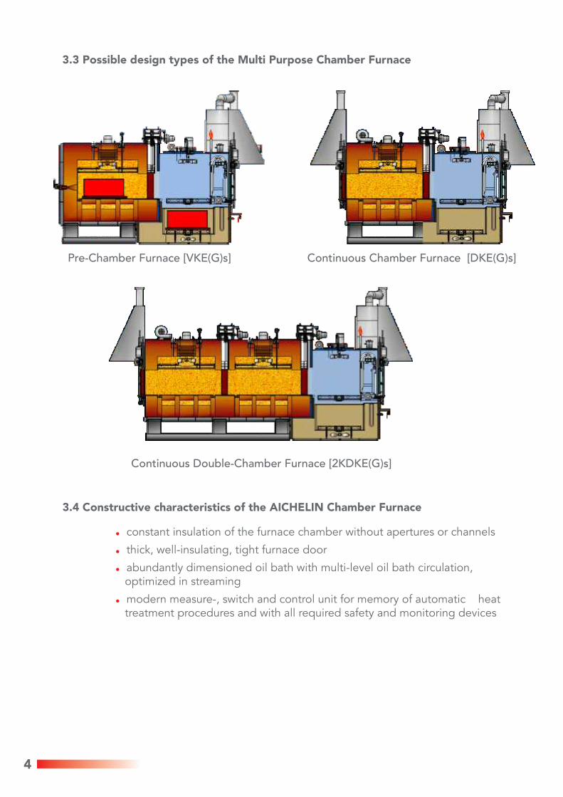
3.3 Possible design types of the Multi Purpose Chamber Furnace
3.4 Constructive characteristics of the AICHELIN Chamber Furnace
constant insulation of the furnace chamber without apertures or channels
thick, well-insulating, tight furnace door
abundantly dimensioned oil bath with multi-level oil bath circulation, optimized in streaming
modern measure-, switch and control unit for memory of automatic heat treatment procedures and with all required safety and monitoring devices
!
!
!
!
Continuous Double-Chamber Furnace [2KDKE(G)s]
Pre-Chamber Furnace [VKE(G)s] Continuous Chamber Furnace [DKE(G)s]
5
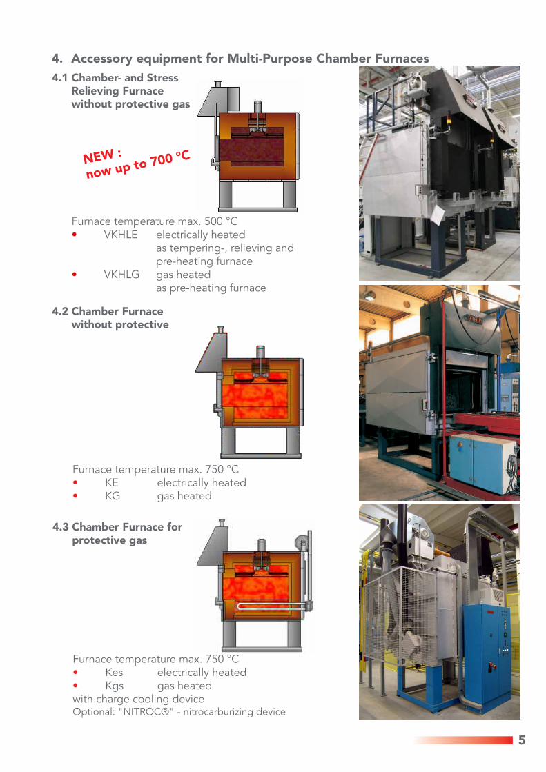
Furnace temperature max. 750 °CKes electrically heatedKgs gas heated
with charge cooling deviceOptional: "NITROC®" - nitrocarburizing device
••
Furnace temperature max. 750 °CKE electrically heatedKG gas heated
••
4.2 Chamber Furnace without protective
4.3 Chamber Furnace for protective gas
4.1 Chamber- and Stress Relieving Furnace without protective gas
4. Accessory equipment for Multi-Purpose Chamber Furnaces
Furnace temperature max. 500 °CVKHLE electrically heated
as tempering-, relieving andpre-heating furnace
VKHLG gas heatedas pre-heating furnace
•
•
NEW :
now up to 700 °C
6
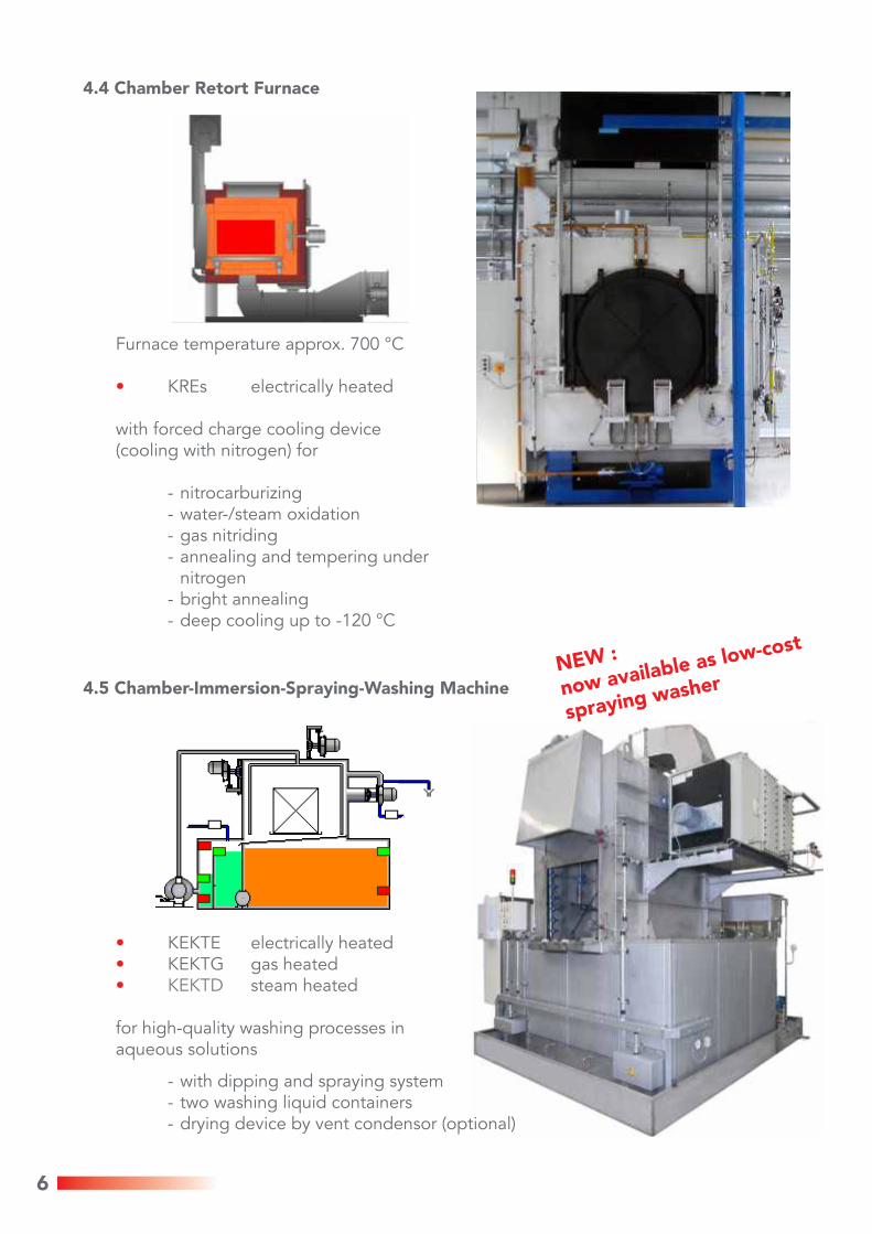
Furnace temperature approx. 700 °C
KREs electrically heated
with forced charge cooling device(cooling with nitrogen) for
- nitrocarburizing- water-/steam oxidation- gas nitriding- annealing and tempering under
nitrogen - bright annealing- deep cooling up to -120 °C
•
•••
KEKTE electrically heatedKEKTG gas heated
steam heated
for high-quality washing processes inaqueous solutions
- with dipping and spraying system - two washing liquid containers- drying device by vent condensor (optional)
KEKTD
4.4 Chamber Retort Furnace
4.5 Chamber-Immersion-Spraying-Washing Machine
NEW :
now available as low-cost
spraying washer
7
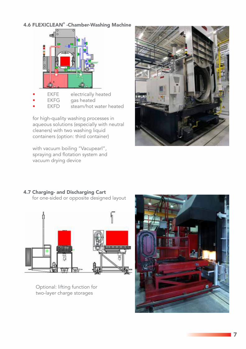
Optional: lifting function for two-layer charge storages
•••
EKFE electrically heatedEKFG gas heatedEKFD steam/hot water heated
for high-quality washing processes inaqueous solutions (especially with neutral cleaners) with two washing liquid containers (option: third container)
with vacuum boiling “Vacupearl”, spraying and flotation system and vacuum drying device
4.7 Charging- and Discharging Cartfor one-sided or opposite designed layout
®4.6 FLEXICLEAN -Chamber-Washing Machine
8
5. Exemples of Installations for Mulit-Purpose Chamber Furnaces
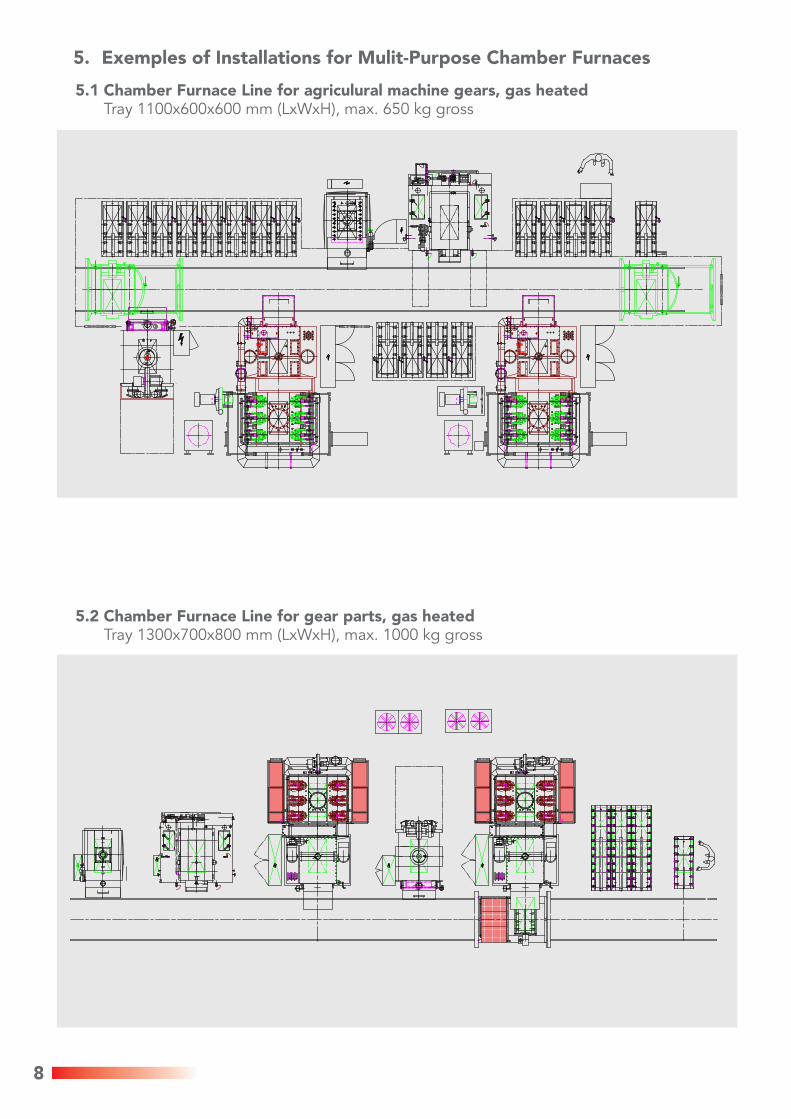
5.1 Chamber Furnace Line for agriculural machine gears, gas heatedTray 1100x600x600 mm (LxWxH), max. 650 kg gross
5.2 Chamber Furnace Line for gear parts, gas heatedTray 1300x700x800 mm (LxWxH), max. 1000 kg gross
9
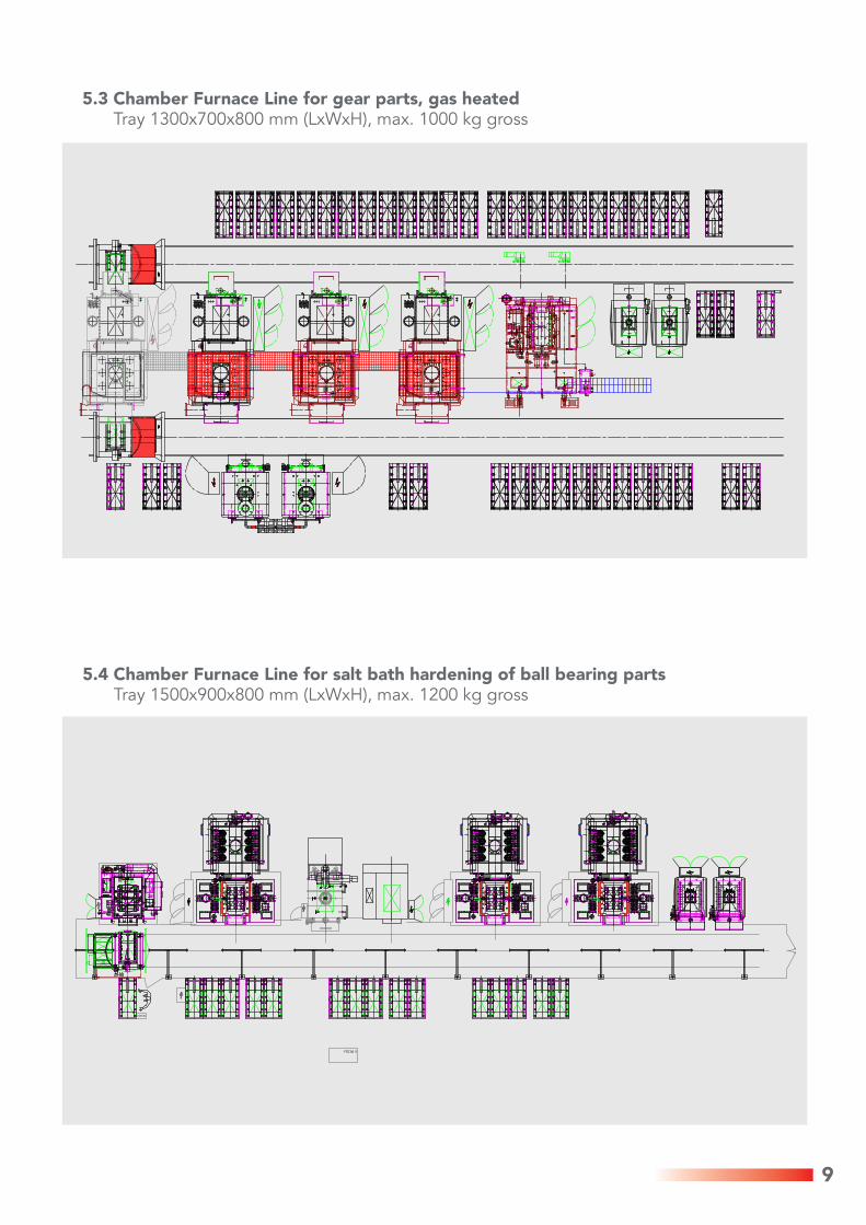
5.4 Chamber Furnace Line for salt bath hardening of ball bearing partsTray 1500x900x800 mm (LxWxH), max. 1200 kg gross
5.3 Chamber Furnace Line for gear parts, gas heated Tray 1300x700x800 mm (LxWxH), max. 1000 kg gross
10
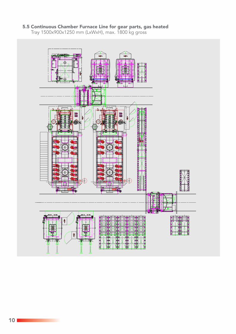
5.5 Continuous Chamber Furnace Line for gear parts, gas heatedTray 1500x900x1250 mm (LxWxH), max. 1800 kg gross
11
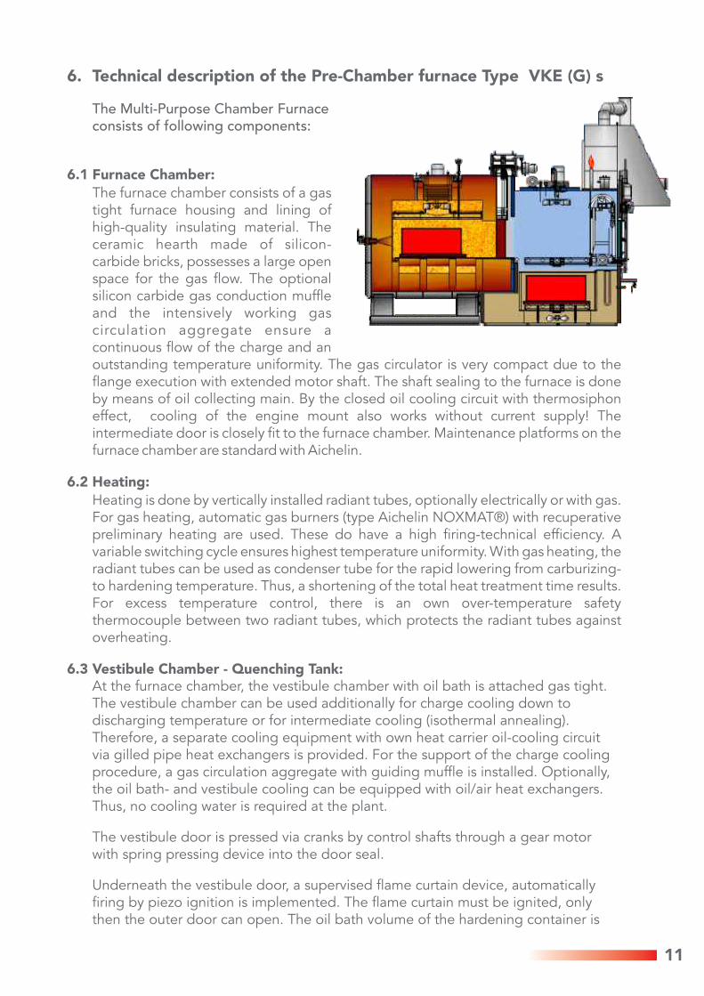
6. Technical description of the Pre-Chamber furnace Type VKE (G) s
The Multi-Purpose Chamber Furnace consists of following components:
6.1 Furnace Chamber:
The furnace chamber consists of a gas tight furnace housing and lining of high-quality insulating material. The ceramic hearth made of silicon-carbide bricks, possesses a large open space for the gas flow. The optional silicon carbide gas conduction muffle and the intensively working gas circulation aggregate ensure a continuous flow of the charge and an outstanding temperature uniformity. The gas circulator is very compact due to the flange execution with extended motor shaft. The shaft sealing to the furnace is done by means of oil collecting main. By the closed oil cooling circuit with thermosiphon effect, cooling of the engine mount also works without current supply! The intermediate door is closely fit to the furnace chamber. Maintenance platforms on the furnace chamber are standard with Aichelin.
6.2 Heating:
Heating is done by vertically installed radiant tubes, optionally electrically or with gas. For gas heating, automatic gas burners (type Aichelin NOXMAT®) with recuperative preliminary heating are used. These do have a high firing-technical efficiency. A variable switching cycle ensures highest temperature uniformity. With gas heating, the radiant tubes can be used as condenser tube for the rapid lowering from carburizing- to hardening temperature. Thus, a shortening of the total heat treatment time results. For excess temperature control, there is an own over-temperature safety thermocouple between two radiant tubes, which protects the radiant tubes against overheating.
6.3 Vestibule Chamber - Quenching Tank:At the furnace chamber, the vestibule chamber with oil bath is attached gas tight. The vestibule chamber can be used additionally for charge cooling down to discharging temperature or for intermediate cooling (isothermal annealing). Therefore, a separate cooling equipment with own heat carrier oil-cooling circuit via gilled pipe heat exchangers is provided. For the support of the charge cooling procedure, a gas circulation aggregate with guiding muffle is installed. Optionally, the oil bath- and vestibule cooling can be equipped with oil/air heat exchangers. Thus, no cooling water is required at the plant.
The vestibule door is pressed via cranks by control shafts through a gear motor with spring pressing device into the door seal.
Underneath the vestibule door, a supervised flame curtain device, automatically firing by piezo ignition is implemented. The flame curtain must be ignited, only then the outer door can open. The oil bath volume of the hardening container is
12
optimally adapted to the charges. The double-walled housing execution with oil detector safely avoids environmental-damaging oil leakages.
The oil level in the hardening container can be supervised by a minimum-maximum indication. Oil cooling is done by means of heat exchangers (oil/water or oil/air). The oil bath heating is carried out electrically by dipping heating elements. The oil circulation is reached by means of two oil circulation aggregates with two adjustable numbers of revolutions.
Via oil guidance channels and oil guide plates, attached closely to the charge, a targeted, obligatory flow of the charge takes place. This is particularly important with closely packed charges for a constant hardening result.
Depending upon need, the hardening bath can be equipped additionally with intensified oil bath circulation capacity and with program controlled continuously adjustable circulation capacity of the oil bath circulation aggregates.
6.4 Lowering platform, charge transport:
The lowering platform is carried out in two layers, thus you can charge the furnace again , while a charge stays in the oil bath. In the vestibule chamber, the automatically working tray transport equipment is implemented.
The cooperation of the high speeds of lowering platform and intermediate transport results in very short moving times; for example for the multi purpose chamber furnace size 3: start from the furnace chamber up to complete immersing into the oil bath approx. 15 seconds.
All drives are carried out by electrical motors with safe end position. Hand wheels are provided for the first drive adjustment and for the emergency operation.
6.5 Safety device:In order to save the charge from damage with power failures resp. with disturbances, the multi purpose chamber furnace is equipped with an automatic N -safety gas supply device. 2
Further, all failures of energy supply, disturbances of the drives, heating etc. are signalized as failure report.
6.6 Gas supply:
The multi purpose chamber furnace can be designed with different kinds of gas supply. Endogas, N -methanol or direct gas supply with air, propane, natural gas or 2
acetone are used as protective gases.
As additional gases, propane, natural gas, LPG gas, acetone and other liquid carburizing media can be used.
The automatic control of the carbon level is done according to standard by oxygen probe (alternatively by Lambda probe).
13
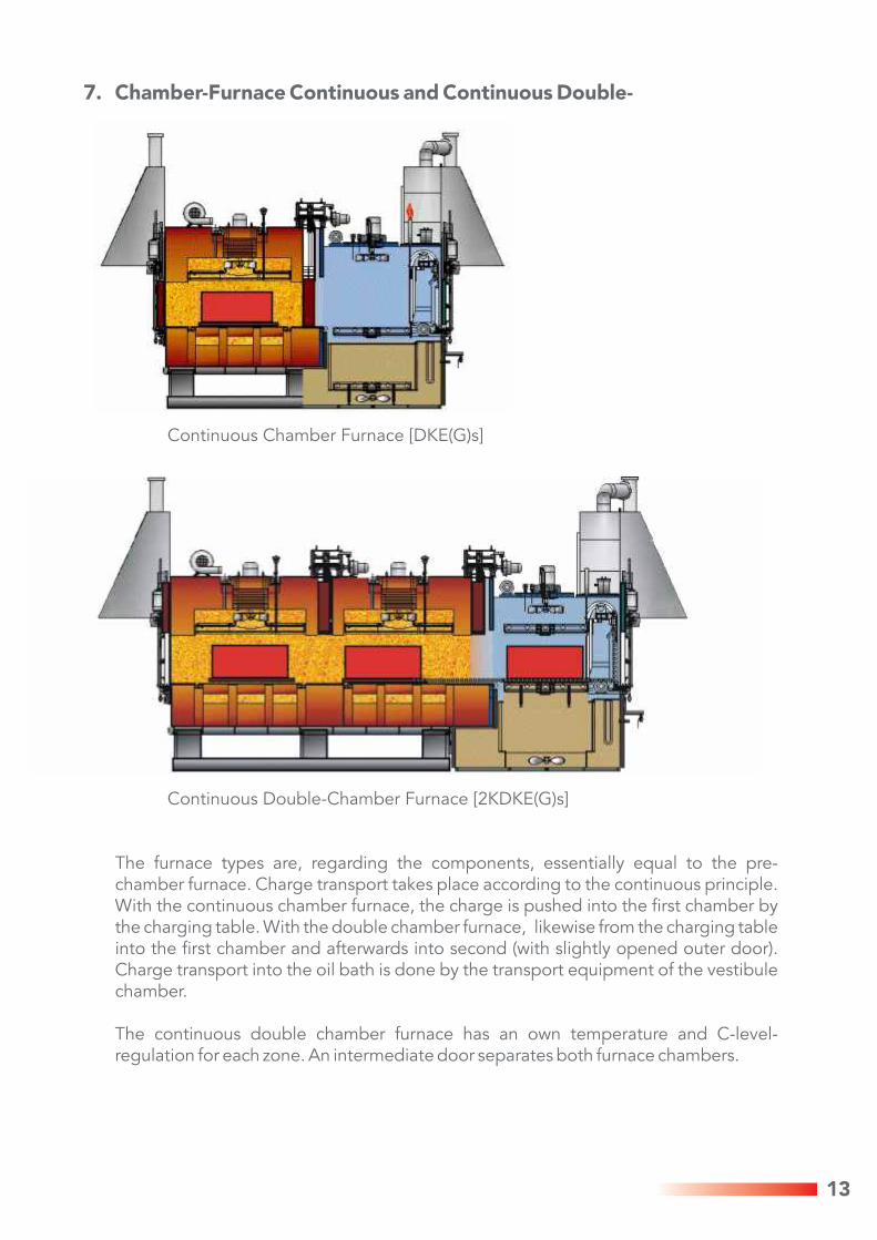
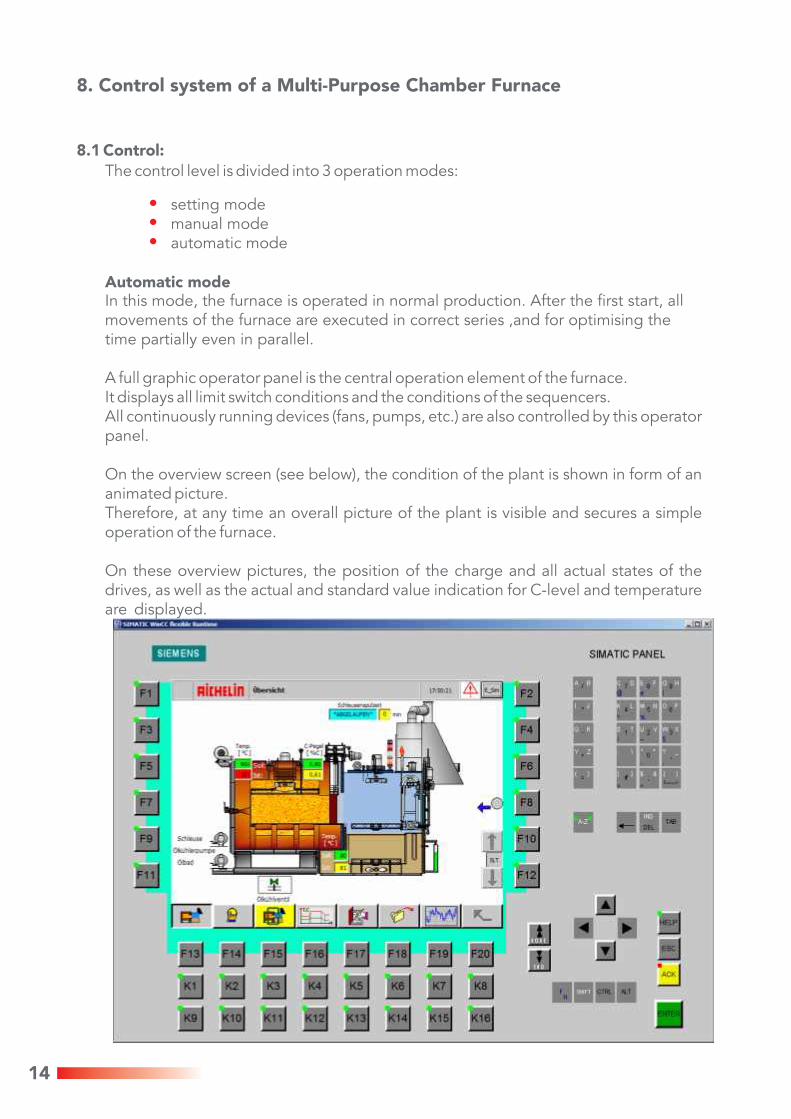
7. Chamber-Furnace Continuous and Continuous Double-
Continuous Chamber Furnace [DKE(G)s]
Continuous Double-Chamber Furnace [2KDKE(G)s]
The furnace types are, regarding the components, essentially equal to the pre-chamber furnace. Charge transport takes place according to the continuous principle. With the continuous chamber furnace, the charge is pushed into the first chamber by the charging table. With the double chamber furnace, likewise from the charging table into the first chamber and afterwards into second (with slightly opened outer door). Charge transport into the oil bath is done by the transport equipment of the vestibule chamber.
The continuous double chamber furnace has an own temperature and C-level-regulation for each zone. An intermediate door separates both furnace chambers.
14
8. Control system of a Multi-Purpose Chamber Furnace
8.1 Control:
The control level is divided into 3 operation modes:
setting modemanual modeautomatic mode
Automatic modeIn this mode, the furnace is operated in normal production. After the first start, all movements of the furnace are executed in correct series ,and for optimising the time partially even in parallel.
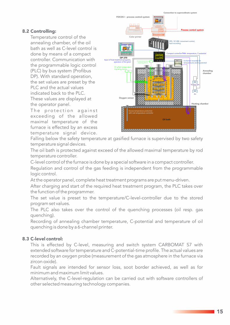
A full graphic operator panel is the central operation element of the furnace.It displays all limit switch conditions and the conditions of the sequencers.All continuously running devices (fans, pumps, etc.) are also controlled by this operator panel.
On the overview screen (see below), the condition of the plant is shown in form of an animated picture. Therefore, at any time an overall picture of the plant is visible and secures a simple operation of the furnace.
On these overview pictures, the position of the charge and all actual states of the drives, as well as the actual and standard value indication for C-level and temperature are displayed.
15
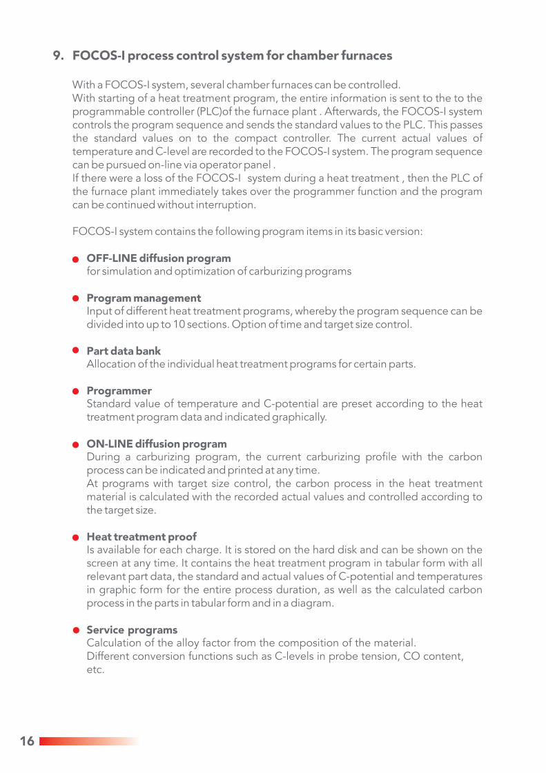
8.2 Controlling:
Temperature control of the annealing chamber, of the oil bath as well as C-level control is done by means of a compact controller. Communication with the programmable logic control (PLC) by bus system (Profibus DP). With standard operation, the set values are preset by the PLC and the actual values indicated back to the PLC. These values are displayed at the operator panel.
T h e p r o t e c t i o n a g a i n s t exceeding of the allowed maximal temperature of the furnace is effected by an excess temperature signal device. Falling below the safety temperature at gasified furnace is supervised by two safety temperature signal devices.
The oil bath is protected against exceed of the allowed maximal temperature by rod temperature controller.
C-level control of the furnace is done by a special software in a compact controller.
Regulation and control of the gas feeding is independent from the programmable logic control.
At the operator panel, complete heat treatment programs are put menu-driven.
After charging and start of the required heat treatment program, the PLC takes over the function of the programmer.
The set value is preset to the temperature/C-level-controller due to the stored program set values.
The PLC also takes over the control of the quenching processes (oil resp. gas quenching).
Recording of annealing chamber temperature, C-potential and temperature of oil quenching is done by a 6-channel printer.
8.3 C-level control:
This is effected by C-level, measuring and switch system CARBOMAT S7 with extended software for temperature and C-potential-time profile. The actual values are recorded by an oxygen probe (measurement of the gas atmosphere in the furnace via zircon oxide). Fault signals are intended for sensor loss, soot border achieved, as well as for minimum and maximum limit values. Alternatively, the C-level-regulation can be carried out with software controllers of other selected measuring technology companies.
FOCOS I - process control system
Connection to superordinate system
Process control system
SPS / S7-300: movement control,fault recording
Compact controller-PMA: temperature, C-potential
6-channel recorder fortemperatures and C-potential
Annealing chamber
Supply gas
Air
Heating chamber
Excess temperature protection with rod-temperature-controller
Oxygen sensor
2x safety-temperature - signaling device
Excess temperature - signaling device
Input of heat-treatment-programs, operation of the plant
OP 270
Color printer
Oil bath
16
9. FOCOS-I process control system for chamber furnaces
With a FOCOS-I system, several chamber furnaces can be controlled. With starting of a heat treatment program, the entire information is sent to the to the programmable controller (PLC)of the furnace plant . Afterwards, the FOCOS-I system controls the program sequence and sends the standard values to the PLC. This passes the standard values on to the compact controller. The current actual values of temperature and C-level are recorded to the FOCOS-I system. The program sequence can be pursued on-line via operator panel . If there were a loss of the FOCOS-I system during a heat treatment , then the PLC of the furnace plant immediately takes over the programmer function and the program can be continued without interruption.
FOCOS-I system contains the following program items in its basic version:
OFF-LINE diffusion programfor simulation and optimization of carburizing programs
Program managementInput of different heat treatment programs, whereby the program sequence can be divided into up to 10 sections. Option of time and target size control.
Part data bankAllocation of the individual heat treatment programs for certain parts.
ProgrammerStandard value of temperature and C-potential are preset according to the heat treatment program data and indicated graphically.
ON-LINE diffusion programDuring a carburizing program, the current carburizing profile with the carbon process can be indicated and printed at any time. At programs with target size control, the carbon process in the heat treatment material is calculated with the recorded actual values and controlled according to the target size.
Heat treatment proofIs available for each charge. It is stored on the hard disk and can be shown on the screen at any time. It contains the heat treatment program in tabular form with all relevant part data, the standard and actual values of C-potential and temperatures in graphic form for the entire process duration, as well as the calculated carbon process in the parts in tabular form and in a diagram.
Service programsCalculation of the alloy factor from the composition of the material. Different conversion functions such as C-levels in probe tension, CO content, etc.
17
MP270 MP270 MP270
MP270
MP270
compact-controller
compact-controller
compact-controller
Multi-purposechamber furnace
Multi-purposechamber furnace
Multi-purposechamber furnace
Temperingfurnace 750 °C
with Nitroc
Temperingfurnace 500 °C
with prot.gas
750 °Cwith
Nitroc
500 °Cwith
prot.gas
®FLEXICLEANdegreasing
machine
®FLEXICLEAN
degreasingmachine
Profibus DP
Master PLC for transport deviceand data-distribution /-collection
specific printoutby the operator
FOCOS PC
preparative roller path
Multi-Purpose Chamber Furnaces
Tempering Furnaces
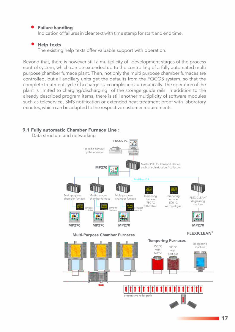
Failure handlingIndication of failures in clear text with time stamp for start and end time.
Help textsThe existing help texts offer valuable support with operation.
Beyond that, there is however still a multiplicity of development stages of the process control system, which can be extended up to the controlling of a fully automated multi purpose chamber furnace plant. Then, not only the multi purpose chamber furnaces are controlled, but all ancillary units get the defaults from the FOCOS system, so that the complete treatment cycle of a charge is accomplished automatically. The operation of the plant is limited to charging/discharging of the storage guide rails. In addition to the already described program items, there is still another multiplicity of software modules such as teleservice, SMS notification or extended heat treatment proof with laboratory minutes, which can be adapted to the respective customer requirements.
9.1 Fully automatic Chamber Furnace Line : Data structure and networking
18
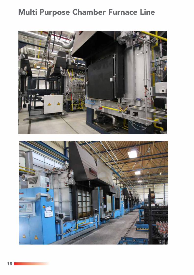
Multi Purpose Chamber Furnace Line
2 19
When are Chamber Furnaces preferentially used?
for small and middle capacities
for different heat treatment procedures
for different kind of parts and high diversity of parts
at charge weights of appr. 150 - 1800 kg (even more in special cases)
if flexibility is required
for different production requirements
if quality with economy is required
!
!
!
!
!
!
!
1. IntroductionDuring the last decades, AICHELIN Group has built far more than 1000 protective gas chamber furnaces and put them into operation. Most of these plants provide their service reliably this very day. This impressively proves the permanent high quality, reliability and economy of these plants. Due to the central meaning of this furnace type, it is being permanently developed and constantly held together with our customers on the highest state of the art. This has now resulted in the creation of three series, where each of them is optimally aligned to your needs. :
The low cost series with superior components. Further description within this folder.
Powerful and worth every Cent. If the standard line does not meet your requirements at 100%. Also described here
The series, that fits into EVERY existing chamber furnace plant. Description see separate folder.
2. Application range of the Multi-Purpose Chamber Furnace
Possible modes of heat treatment:For example:
gas carburizing - with direct quenching
- with intermediate cooling- with charge cooling under protective gasre-carburizingcarbonitriding
®NITROC - nitrocarburizingnitridinghardening in oil or saltnormalizingannealingtempering
!
!
!
!
!
!
!
!
!
AICHELIN Multi-Purpose Chamber Furnace Unit
°C
°C
t
°C °C
t
t
t
Temperature
Temperature
C-Level
Gas Carburizing
C-Level
Gas Carburizing with Intermediate Cooling
C-Level
Annealing
Temperature Temperature
NormalizingVarious annealing programs
Standard-LineStandard-LineStandard-Line
Individual-LineIndividual-LineIndividual-Line
Evolution-LineEvolution-LineEvolution-Line
References
Individual-LineIndividual-LineIndividual-Line
Standard-LineStandard-LineStandard-Line
TI02-01/Mrz2010/E
The Universal Heat Treatment PlantThe Universal Heat Treatment Plant
http://www.aichelin.com
Subject to technical changes® ® ® ® ®AICHELIN , NOXMAT , NITROC , ENDOMAT , FLEXICLEAN
are registered trademarks
AICHELIN Ges.m.b.H.Postfach 210A-2340 MödlingPhone (+43) (2236) 236 46 - 0Telefax (+43) (2236) 22 22 [email protected]
AICHELIN Service GmbHPostfach 340D-71603 LudwigsburgPhone (+49) (7141) 6437 - 0Telefax (+49) (7141) 6437 - [email protected]
NOXMAT GmbHRingstraße 7D-09569 OederanPhone (+49) (37292) 65 03-0Telefax (+49) (37292) 65 [email protected]
EMA Indutec GmbHPetersbergstrasse 9D-74909 MeckesheimPhone (+49) (6226) 788 - 0Telefax (+49) (6226) 788 - [email protected]
AICHELIN Heat Treatment Systems (Beijing) Co. Ltd.10 00 86 Beijing, ChinaPhone (+86) (10) 8255 1421Telefax (+86) (10) 8255 [email protected]
SAFED SUISSE SA36, rue Emile-BoéchatCH - 2800 DelémontPhone (+41) (32) 421 44 60Telefax (+41) (32) 421 44 [email protected]
Multi-Purpose Chamber Furnace UnitMulti-Purpose Chamber Furnace Unit


