http://www.revmaterialeplastice.ro MATERIALE PLASTICE ♦54♦No. 4 ♦2017 694 Fatigue Crack Propagation and Charpy Impact Properties in Armor Steel Welds ALEKSANDAR CABRILO 1 *, MIROSLAV CVETINOV 2 1 Faculty of Technical Sciences, University of Novi Sad, Trg D. Obradovica 6, 21000 Novi Sad, Serbia, 2 Faculty of Sciences, University of Novi Sad, Trg D. Obradovica 4, 21000 Novi Sad, Serbia The process of welding armor steel is a complex process because of possible welding faults, appearing in the weld metal zone in the form of cracks and pores. Austenitic filler material is traditionally used for welding armor steels. For heavy structural engineering such as armored military vehicles, which are frequently under the effect of dynamic load, it is important to know the dynamic properties of the most sensitive area of welded joints, the weld metal zone. Due to a significant interest in quantification of material resistance to crack initiation and propagation, the fatigue crack growth rate was measured in the welded metal zone, while the resistance to crack growth in the weld metal was tested by the amount of austenite transformed into martensite. Accordingly, the threshold stress concentration factor was 10 MPa m 1/2 . XRD spectral analysis revealed direct transformation of γ - austenite into α’ -martensite. Key words: Armor steels, Fatigue crack growth, Austenitic stainless steel and Martensitic transformation. Armor steel belongs to the ultra-high tensile strength and hardness group of steels. The welding of armor steel is complicated due to the high percentage of carbon content in the base metal and the presence of faults in the form of cracks and pores [1] in the weld metal zone, whereby fractures may be initiated in the weld metal. Austenitic filler material is traditionally used for armor steel welding because of hydrogen dilution improved in an austenitic phase [2, 3]. The filler material, in armor steel welded joints has lower mechanical properties than the base material, i.e. the filler material is the weakest point of the welded joint [4]. After the welding process, solidification cracking may result from high thermal expansion of the austenitic stainless steel [5,6] and invisible defects may be created in the weld metal zone [7]. For heavy structural engineering, such as armored military vehicles frequently being under the effects of variable loads [8], mechanical properties of welded joints and the weld metal zone must be known. Due to variable loads, cracks created in the weld metal may easily propagate towards the sensitive fusion line, followed by their possible rapid growth [9]. For armored vehicle structures safe and rational dimensioning, it is necessary to know dynamic effects extreme values and time periods. Therefore, there is a significant interest in material resistance related to crack initiation and propagation, as well as in dynamic force conditions. A fatigue crack growth rate characteristic in the linear and threshold region in metal weld is considered as an important property, since it shows a fault – tolerant ability of this part of welded joint [10,11]. Austenitic filler material is unstable and gets transformed into martensite during fatigue crack propagation due to plastic deformation at the crack tip [12]. During the metastable austenite deformation, two types of martensitic structures can be formed: ε- martensite with hexagonal close packed and α’ -martensite, with body centered cubic crystal structure. Austenite into martensite transformation is related to the stacking fault energy. If the stacking fault energy is < 20 J/m 2 , transformation proceeds according to the model:γ→ε→α’ . If it is larger, then the direct γ→α’ transformation occurs [13]. It is known that manganese and nickel stabilize martensite and prevent martensitic transformation. It should be noted that a upper limit of stacking fault energy of austenite-martensite phase transition phase transition varies [14,15]. An amount of austenite transformed into martensite is directly related to crack growth resistance in the weld metal [16]. The main goal of this study was to investigate the impact energy by instrumented pendulum and fatigue crack growth in the Paris region. Martensitic transformation effects on fatigue crack growth in the Paris region were investigated by X – ray diffraction. Fracture surfaces for the impact energy and fatigue crack growth tests were also investigated by Scanning Electron Microscope (SEM) . Subsequently, samples in the weld metal region were studied by tensile strength test, hardness measurements, metallography and chemical analysis. Experimental part Materials and methods Materials and welding process Gas metal arc welding (GMAW) and AWS ER307 solid wire is used for welding armor steel Protac 500. Welding direction is parallel to the rolling direction. Cold rolled plates 12 mm thick are cut to the required dimensions (250 x 100 mm), while V joint under the angle of 55° is prepared by Water Jet Device figure 1. Robot Kuka and Citronix 400A device was used during the welding process testing. Robotic welding is used for human factor effect elimination, in order to allow a fine adjustment of parameters and results repeatability. Wire diameter is 1.0 mm while figure 1 shows V joint dimensions and four - pass welding configuration. * email: [email protected]Fig. 1. Schematic drawing of edge preparation and welding configuration
Fatigue Crack Propagation and Charpy Impact Propertiesin Armor Steel Welds
ALEKSANDAR CABRILO1*, MIROSLAV CVETINOV2
1Faculty of Technical Sciences, University of Novi Sad, Trg D. Obradovica 6, 21000 Novi Sad, Serbia,2 Faculty of Sciences, University of Novi Sad, Trg D. Obradovica 4, 21000 Novi Sad, Serbia
The process of welding armor steel is a complex process because of possible welding faults, appearing inthe weld metal zone in the form of cracks and pores. Austenitic filler material is traditionally used forwelding armor steels. For heavy structural engineering such as armored military vehicles, which are frequentlyunder the effect of dynamic load, it is important to know the dynamic properties of the most sensitive areaof welded joints, the weld metal zone. Due to a significant interest in quantification of material resistance tocrack initiation and propagation, the fatigue crack growth rate was measured in the welded metal zone,while the resistance to crack growth in the weld metal was tested by the amount of austenite transformedinto martensite. Accordingly, the threshold stress concentration factor was 10 MPa m1/2. XRD spectralanalysis revealed direct transformation of γ - austenite into α’ -martensite.
Armor steel belongs to the ultra-high tensile strengthand hardness group of steels. The welding of armor steel iscomplicated due to the high percentage of carbon contentin the base metal and the presence of faults in the form ofcracks and pores [1] in the weld metal zone, wherebyfractures may be initiated in the weld metal. Austeniticfiller material is traditionally used for armor steel weldingbecause of hydrogen dilution improved in an austeniticphase [2, 3]. The filler material, in armor steel welded jointshas lower mechanical properties than the base material,i.e. the filler material is the weakest point of the weldedjoint [4]. After the welding process, solidification crackingmay result from high thermal expansion of the austeniticstainless steel [5,6] and invisible defects may be createdin the weld metal zone [7].
For heavy structural engineering, such as armoredmilitary vehicles frequently being under the effects ofvariable loads [8], mechanical properties of welded jointsand the weld metal zone must be known. Due to variableloads, cracks created in the weld metal may easilypropagate towards the sensitive fusion line, followed bytheir possible rapid growth [9].
For armored vehicle structures safe and rationaldimensioning, it is necessary to know dynamic effectsextreme values and time periods. Therefore, there is asignificant interest in material resistance related to crackinitiation and propagation, as well as in dynamic forceconditions. A fatigue crack growth rate characteristic inthe linear and threshold region in metal weld is consideredas an important property, since it shows a fault – tolerantability of this part of welded joint [10,11].
Austenitic filler material is unstable and gets transformedinto martensite during fatigue crack propagation due toplastic deformation at the crack tip [12]. During themetastable austenite deformation, two types of martensiticstructures can be formed: ε- martensite with hexagonalclose packed and α’ -martensite, with body centered cubiccrystal structure. Austenite into martensite transformationis related to the stacking fault energy. If the stacking faultenergy is < 20 J/m2, transformation proceeds according tothe model:γ→ε→α’ . If it is larger, then the direct γ→α’transformation occurs [13]. It is known that manganese
and nickel stabilize martensite and prevent martensitictransformation. It should be noted that a upper limit ofstacking fault energy of austenite-martensite phasetransition phase transition varies [14,15]. An amount ofaustenite transformed into martensite is directly related tocrack growth resistance in the weld metal [16].
The main goal of this study was to investigate the impactenergy by instrumented pendulum and fatigue crackgrowth in the Paris region. Martensitic transformationeffects on fatigue crack growth in the Paris region wereinvestigated by X – ray diffraction. Fracture surfaces for theimpact energy and fatigue crack growth tests were alsoinvestigated by Scanning Electron Microscope (SEM).Subsequently, samples in the weld metal region werestudied by tensile strength test, hardness measurements,metallography and chemical analysis.
Experimental partMaterials and methodsMaterials and welding process
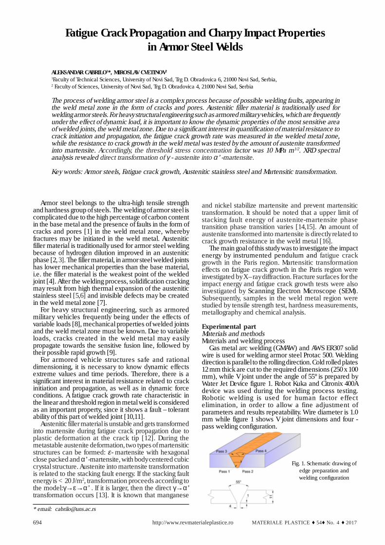
Gas metal arc welding (GMAW) and AWS ER307 solidwire is used for welding armor steel Protac 500. Weldingdirection is parallel to the rolling direction. Cold rolled plates12 mm thick are cut to the required dimensions (250 x 100mm), while V joint under the angle of 55° is prepared byWater Jet Device figure 1. Robot Kuka and Citronix 400Adevice was used during the welding process testing.Robotic welding is used for human factor effectelimination, in order to allow a fine adjustment ofparameters and results repeatability. Wire diameter is 1.0mm while figure 1 shows V joint dimensions and four -pass welding configuration.
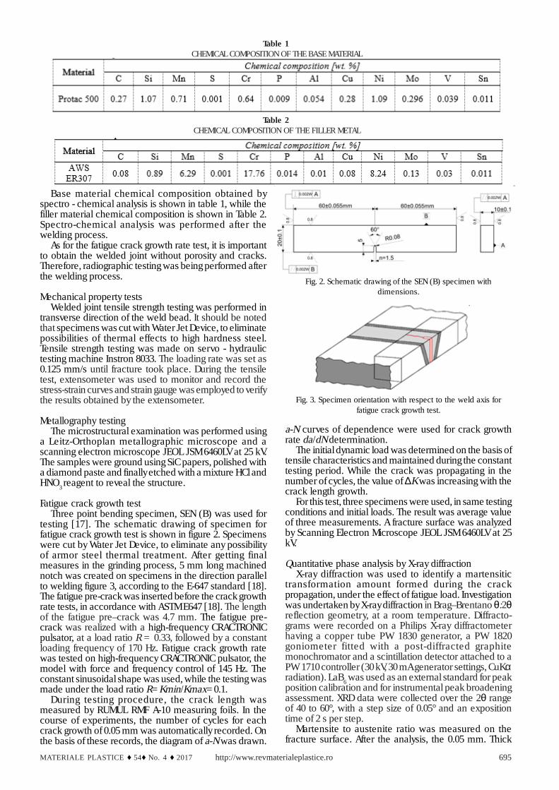
Base material chemical composition obtained byspectro - chemical analysis is shown in table 1, while thefiller material chemical composition is shown in Table 2.Spectro-chemical analysis was performed after thewelding process.
As for the fatigue crack growth rate test, it is importantto obtain the welded joint without porosity and cracks.Therefore, radiographic testing was being performed afterthe welding process.
Mechanical property testsWelded joint tensile strength testing was performed in
transverse direction of the weld bead. It should be notedthat specimens was cut with Water Jet Device, to eliminatepossibilities of thermal effects to high hardness steel.Tensile strength testing was made on servo - hydraulictesting machine Instron 8033. The loading rate was set as0.125 mm/s until fracture took place. During the tensiletest, extensometer was used to monitor and record thestress-strain curves and strain gauge was employed to verifythe results obtained by the extensometer.
Metallography testingThe microstructural examination was performed using
a Leitz-Orthoplan metallographic microscope and ascanning electron microscope JEOL JSM 6460LV at 25 kV.The samples were ground using SiC papers, polished witha diamond paste and finally etched with a mixture HCl andHNO3 reagent to reveal the structure.
Fatigue crack growth testThree point bending specimen, SEN (B) was used for
testing [17]. The schematic drawing of specimen forfatigue crack growth test is shown in figure 2. Specimenswere cut by Water Jet Device, to eliminate any possibilityof armor steel thermal treatment. After getting finalmeasures in the grinding process, 5 mm long machinednotch was created on specimens in the direction parallelto welding figure 3, according to the E-647 standard [18].The fatigue pre-crack was inserted before the crack growthrate tests, in accordance with ASTM E647 [18]. The lengthof the fatigue pre–crack was 4.7 mm. The fatigue pre-crack was realized with a high-frequency CRACTRONICpulsator, at a load ratio R = 0.33, followed by a constantloading frequency of 170 Hz. Fatigue crack growth ratewas tested on high-frequency CRACTRONIC pulsator, themodel with force and frequency control of 145 Hz. Theconstant sinusoidal shape was used, while the testing wasmade under the load ratio R=Kmin/Kmax=0.1.
During testing procedure, the crack length wasmeasured by RUMUL RMF A-10 measuring foils. In thecourse of experiments, the number of cycles for eachcrack growth of 0.05 mm was automatically recorded. Onthe basis of these records, the diagram of a-N was drawn.
a-N curves of dependence were used for crack growthrate da/dN determination.
The initial dynamic load was determined on the basis oftensile characteristics and maintained during the constanttesting period. While the crack was propagating in thenumber of cycles, the value of ∆K was increasing with thecrack length growth.
For this test, three specimens were used, in same testingconditions and initial loads. The result was average valueof three measurements. A fracture surface was analyzedby Scanning Electron Microscope JEOL JSM 6460LV at 25kV.
Quantitative phase analysis by X-ray diffractionX-ray diffraction was used to identify a martensitic
transformation amount formed during the crackpropagation, under the effect of fatigue load. Investigationwas undertaken by X-ray diffraction in Brag–Brentano θ:2θreflection geometry, at a room temperature. Diffracto-grams were recorded on a Philips X-ray diffractometerhaving a copper tube PW 1830 generator, a PW 1820goniometer fitted with a post-diffracted graphitemonochromator and a scintillation detector attached to aPW 1710 controller (30 kV, 30 mA generator settings, CuKαradiation). LaB6 was used as an external standard for peakposition calibration and for instrumental peak broadeningassessment. XRD data were collected over the 2θ rangeof 40 to 60°, with a step size of 0.05° and an expositiontime of 2 s per step.
Martensite to austenite ratio was measured on thefracture surface. After the analysis, the 0.05 mm. Thick
Table 2 CHEMICAL COMPOSITION OF THE FILLER METAL
Table 1 CHEMICAL COMPOSITION OF THE BASE MATERIAL
Fig. 2. Schematic drawing of the SEN (B) specimen withdimensions.
Fig. 3. Specimen orientation with respect to the weld axis forfatigue crack growth test.
layer was removed, upon which the measurementprocedure of austenitic transformation amount wasrepeated. The repeatability continued to 25% of theaustenitic transformation value in martensite. Anexperimental XRD patterns decomposition (profile fitting)was performed using pseudo - Voigt function on eachdiffraction peak and linear function on backgroundradiation. For quantitative phase analysis RIR method wasemployed [19]. The RIR method scales all diffraction datato the standard. By convention, corundum is used as aninternational reference. The scale factor, I/Ic, wasexperimentally determined from the pattern strongest lineratio, I, to the corundum Ic strongest line intensity, in a 50/50 weight mixture.
As to determination of martensite and austenite phasesweight contents, their scaling factors were obtained fromthe ICDD PDF-2 database (PDF 41293, PDF 441292, PDF897245 and PDF 330397). Due to the heavy peakoverlapping in the 43° - 44.5° 2θ region, this method couldonly be employed on the second most intense peak ofboth martensite, I2mart, and austenite, I2aust, at ~45.0° 2θ[20] and ~50.7° 2θ[21,22], respectively. Intensity ratios ofthe two strongest lines for martensite, (I/I2)mart, andaustenite phase, (I/I2)aust, were thus obtained from thesame database. The following equation served forcalculation to be done:
where Xaust = 1-Xmart and Xmart are weight fractions ofaustenite and martensite phases, respectively.
Results and discussionsRadio-graphical results show no visible cracks and
porosity in the welded joint, which, according to EN ISO5817:2014 [23] standard, was B class rated.
Tensile testing resultsWhile tensile characteristics were being tested, a
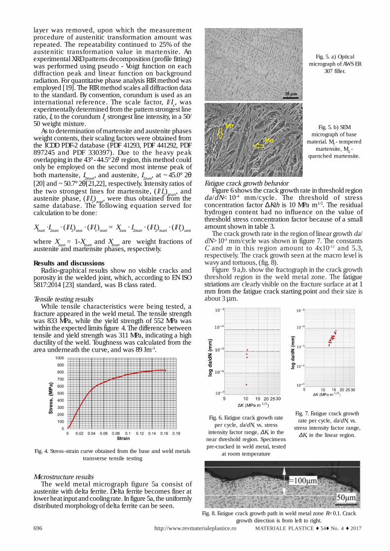
fracture appeared in the weld metal. The tensile strengthwas 833 MPa, while the yield strength of 552 MPa waswithin the expected limits figure 4. The difference betweentensile and yield strength was 311 MPa, indicating a highductility of the weld. Toughness was calculated from thearea underneath the curve, and was 89 Jm-3.
Fatigue crack growth behaviorFigure 6 shows the crack growth rate in threshold region
da/dN<10-4 mm/cycle. The threshold of stressconcentration factor ∆Kth is 10 MPa m1/2. The residualhydrogen content had no influence on the value ofthreshold stress concentration factor because of a smallamount shown in table 3.
The crack growth rate in the region of linear growth da/dN>10-4 mm/cycle was shown in figure 7. The constantsC and m in this region amount to 4x10-11 and 5.3,respectively. The crack growth seen at the macro level iswavy and tortuous, (fig. 8).
Figure 9 a,b. show the fractograph in the crack growththreshold region in the weld metal zone. The fatiguestriations are clearly visible on the fracture surface at at 1mm from the fatigue crack starting point and their size isabout 3 µm.
Fig. 4. Stress–strain curve obtained from the base and weld metalstransverse tensile testing
Fig. 5. a) Opticalmicrograph of AWS ER
307 filler.
Fig. 5. b) SEMmicrograph of base
material. MT - temperedmartensite, MQ -
quenched martensite.
Fig. 6. Fatigue crack growth rateper cycle, da/dN, vs. stress
intensity factor range, ∆K, in thenear threshold region. Specimenspre-cracked in weld metal, tested
at room temperature
Fig. 7. Fatigue crack growthrate per cycle, da/dN, vs.
stress intensity factor range,∆K, in the linear region.
Fig. 8. Fatigue crack growth path in weld metal zone R=0.1. Crackgrowth direction is from left to right.
Microstructure resultsThe weld metal micrograph figure 5a consist of
austenite with delta ferrite. Delta ferrite becomes finer atlower heat input and cooling rate. In figure 5a, the uniformlydistributed morphology of delta ferrite can be seen.
The fractrograph in the linear crack growth region isshown in figure 10 a and b. The fatigue striations formed inthis region are 4 to 5 times larger than in the thresholdregion, and are up to 15µm large.
XRD spectral analysisFigure 11 shows the X-ray diffraction results of the
deformation-induced α’ martensite. The changing amountsare shown per level, in relation to the fracture surface. Theresults show two phases, austenite and martensite. Bothphases have two peaks, austenite with peaks of 2θ from43.2-43.6 and 50.4-50.9, and martensite with its peaks at43.5-44.2, 44.8 and 45.0.
Since higher surface roughness causes increased diffuseX-ray scattering, peak intensities inversely correlate withthe thickness of the specimens under investigation.Nevertheless, using the RIR method (reference intensityratio), the ratio of integrated intensities of α’ martensiteand austenite diffraction peaks reliably indicates theirweight ratio in surface layers.
The most intense peaks of α’ martensite and austeniteoverlap not only in our specimen, but in numerous alloyspublished in cr ystallographic databases [19]. Theuncertainty, inherent in heavily overlapping peaksdeconvolution, makes them unsuitable for weight ratiodetermination. Therefore, the second most intense peakswere used. These peaks are only twice less intense than
their stronger counterparts and therefore are absolutelysufficient for precise weight ratio calculation.
Table 3 shows a changes percentage per level in relationto the fracture surface. α ’martensite was detected atdistances up to 0.25 mm under the fracture surface. Thegreatest transformation of austenite into α’martensite was55%, seen on the fracture surface. The amount of α ’martensite declines with a distance by an average of H”5%/0.05 mm, in the depth perception tests. At the distance of0.25 mm, the amount of transformed austenite fell to 24%.
Martensitic transformation took place due to plasticdeformation at the crack tip. The plastic zone radius,according to Von Mises criterion eq. (1), in the linear growthregion, amounts to r*ip=0.14 mm.
(1)
Schram and Reed [24] established a formula forstacking fault energy calculation, an energy affecting amartensitic transformation possibility:
(2)
The stacking fault energy for austenitic filler material is32 mJ/m2. This slightly higher stacking fault energy resultsfrom the higher manganese and nickel content whichexists in austenitic filler material.
It is known that welded joints are very heterogeneous,since they include weld metal, heat affected zone (HAZ)and base metal. Armor steel welded joints are expected tohave a tensile strength not lower than 550 MPa, in order tosatisfy the requirements of MIL-STD-1185 [25]. The tensilestrength achieved in this research of 833 MPa is rather highfor austenitic filler material and significantly higher thanthe tensile strength obtained by other authors [ 26].
Fatigue induced fracture depends on external factorssuch as load and internal factors such as mechanicalproperties of materials and microstructure. It is known thatin stainless steel, being metastable materials, austenitetransformation into martensite may occur during a fatiguecrack growth; this is the result of intensive plasticdeformation at the crack tip. X-ray diffraction showed thedirect transformation of austenite into α’ martensite, whatis typical for stainless steel with higher stacking fault energy.Martensitic transformation in these steels causes anincrease in volume [27]. The resulting stress and strainfields which appear at the crack tip should be taken into
Table 3α’- MARTENSITE
VOLUMEFRACTIONS VS.
SPECIMENTHICKNESS
Fig. 11. XRD Diffractograms of specimensunder investigation
Fig. 9. SEM fractography at 1 mm from the fatigue crack startingpoint.
Fig. 10. SEM fractography at 6.5 mm from the fatigue crack startingpoint.
account during determination of the stress intensity factor[28,29]. Phase transformations taking place at the cracktip [30] decrease the crack growth rate in the linear region[31]. Martensitic transformation takes place only in thethin layer close to the fracture surface. According to eq.(1), the plastic zone in the region of linear growth has aradius of 0.14 mm, which matches the X-ray diffractionresults, showing that the zone of intensive martensitictransformation is at a depth of 0.1 mm.
On the basis of transformed martensite percentage, itcan be noticed the crack growth is rather difficult. Deltaferrite in the austenitic base of the weld metal gives rise tocrack deflection and spreading, thus decreasing the stressintensity factor at the crack tip; it reduces the crack growthrate in this region.
It is known that microstructural characteristics are veryimportant for fatigue crack growth; so, the coefficientdefining the crack growth in the Paris region has slightlyhigher values than usual, which can be explained by themulti - pass weld having an irregular hardenedmicrostructure.
In this research, the crack growth was normallymonitored in respect to the growth direction of α ’-austenitic dendrite. Regarding to austenitic filler materialand cast structure, slightly lower threshold values of stressconcentration factor should be expected in the case ofcracks growing in the direction parallel to the columnargrain [32].
ConclusionsOn the basis of the results presented in this work, the
following conclusions may be made:Tensile strength of weld metal in the specimen welded
with austenitic filler metal reached 833 MPa, which isgreater than results published for the same filler metal inresearches of manual welding.
An effect of the relatively high hardness combined witha high impact energy achieved by using austenitic fillermaterial allows increased resistance to crack initiationwith a fatigue crack threshold ∆Kth = 10 MPa m1/2, it resultsin better fatigue performance of the joint. Austenitic fillermaterial showed high threshold stress concentration factor.Microscopic testing showed the rough fracture surface.The crack’s growth path is very wavy and tortuous.
Direct transformation of γ - austenite into α’- martensitewas ascertained in austenitic filler material AWS 307, witha fault energy of 32 mJ/m2.
Acknowledgements: The authors would like to thank PhD Zijah Burzic,and Military Technical Institute for Mechanical Testing. This studywas financially supported by the Ministry of Education, Science andTechnological Development of the Republic of Serbia through theProject Nos. ON 174004. This work was partly supported by the researchgrant no. OI171015 from the Ministry of Education, Science andTechnological Development of the Republic of Serbia.
References1.ATABAKI, M.M., MA, J., YANG, G., KOVACEVIC, R., Hybrid laser/arcwelding of advanced high strength steel in different butt jointconfigurations, Mater. Des. 64 (2014) 573–587.2.KUZMIKOVA, L., NORRISH, J., LI, H., CALLAGHAN, M., Research toestablish a systematic approach to safe welding proceduredevelopment using austenitic filler material for fabrication of highstrength steel. 16th International Conference on the Joining ofMaterials (2011) 1-133. BORDEASU, I., MICU, L. M., MITELEA, I., UTU, I. D., PIRVULESCU,L. D., SIRBU, N. A., Cavitation Erosion of HVOF Metal-ceramic
Composite Coatings Deposited onto Duplex Stainless Steel Substrate,Mat. Plast.,53, no. 4, 2016, p. 7814 MAGUDEESWARAN, G., BALASUBRAMANIAN, V., MADHUSUDHAN,R.G., Effect of welding processes and consumables on high cyclefatigue life of high strength, quenched and tempered joints, Mater.Des. 29 (2008) 1821-1827.5. RANJBARNODEH, E., POURALIAKBAR, H., KOKABI, A. H., FiniteElement Simulation of Carbide Precipitation in Austenitic StainlessSteel 304, Int. J. Mech. Applic. 2 (2012) 117–123.6. BORDEASU, I.,MITELEA, I., SALCIANU, L., CRACIUNESCU, CM.,Cavitation Erosion Mechanisms of Solution Treated X5CrNi18-10Stainless Steels, JOURNAL OF TRIBOLOGY-TRANSACTIONS OF THEASME, Volume: 138 Issue: 3, DOI: 10.1115/1.4032489, JUL 2016, ArticleNumber: 0311027. ALAM, M.M., BARSOUM, Z., JONSEN, P., KAPLAN, A.F.H., HAGGBLAD,H.Å., Influence of defects on fatigue crack propagation in laser hybridwelded eccentric fillet joint, Eng. Fract. Mech. 78 (2011) 2246–2258.8. CIMPOERU, S.J., The Measurement of Dynamic Structural Stressesin a Light Armoured Vehicle. M.Eng.Sci, GradieAust, In 5 th AustralianAeronautica Conference, Melbourne (1993) 13-15.9. SHAH KHAN, M.Z., ALKEMADE, S.J., WESTON, G.M., WIESE, D.G.,Variable-amplitude fatigue testing of a high hardness armour steel.Int. J. Fatigue Vol.20, No.3 (1998) 233-239.10. MARTELO, D.F., MATEO, A.M., CHAPETTI M.D., Fatigue crack growthof a metastable austenitic stainless steel, Int. J. Fatigue 80 (2015) 406–416.11. SHANG, Y.B, SHI, H.J., WANG, Z.X., ZHANG, G.D., In-situ SEM studyof short fatigue crack propagation behavior in a dissimilar metalwelded joint of nuclear power plant, Mater. Des. 88 (2015) 598–609.12. MARTELO, D.F., MATEO, A., CHAPETTI, M. D., Crack closure andfatigue crack growth near threshold of a metastable austenitic stainlesssteel, Int. J. Fatigue 77 (2015) 64–77.13. MOALLEMI, M., KERMANPUR, A., NAJAFIZADEH, A., REZAEE, A.,BAGHBADORANI, S.H., NEZHADFAR, D.P., Deformation-inducedmartensitic transformation in a 201 austenitic steel. The synergy ofstacking fault energy and chemical driving force, Mater.Sci. Eng. A 653(2016) 147–152.14. ALLAIN, S., CHATEAU, J.P., BOUAZIZ, O., MIGOT, S., GUELTON, N.,Correlations between the calculated stacking fault energy and theplasticity mechanisms in Fe–Mn–C alloys, Mater. Sci. Eng. 387–389(2004) 158–62.15. REMY, L., PINEAU, A., Twinning and strain-induced FCC’!HCPtransformation in the Fe–Mn–Cr–C system, Mater. Sci. Eng. 28 (1977)99–107.16. MEI, Z., MORRIS, J.W., Influence of deformation-induced martensiteon fatigue crack propagation in 304-type steels, Metall Trans A 21 (12)(1990) 3137–52.17.MONAZZAH, A. H., POURALIAKBAR, H., BAGHERI, R., REIHANI S.M. S., Toughness behavior in roll-bonded laminates based on AA6061/SiCp composites, Mater.Sci. Eng. A 598 (2014) 162–173.18. ***ASTM E647-08: Standard test method for measurement of fatiguecrack growth rates. In Annual Book of ASTM Standards, Volume 03.01,West Conshohocken (PA): ASM International; 200419. SNYDER, R.L., The Use of Reference Intensity Ratios in X-RayQuantitative Analysis, Powder Diffraction, 7, (1992), 186-193.20. ***ICDD, PDF-2 (Database), #44-1293, International Centre forDiffraction Data, Newtown Square, PA, USA., (2003).21. ARBUZOV, M., GOLUB, S.Y., KARPETS, M., Structure of austeniteordering in chromium steels, FizikaMetallov i Metallovedenie, 62(1986) 108-111.22. AMAR. K.D., DAVID, C., MURDOCK, C.M., SPEER, J.G., MATLOCK,K.D., Quantitative measurement of deformation-induced martensitein 304 stainless steel by X-ray diffraction, Scr. Mater. 50 (2004) 1445-1449.23.*** EN ISO 5817:2014.Welding. Fusion-welded joints in steel, nickel,titanium and their alloys (beam welding excluded). Quality levels forimperfections.24. SCHARAM, R.E., REED, R.P., Stacking fault energies of austeniticstainless steels, Metall Trans A (1975) 6A:1345–51.
25. ***MIL-STD-1185. Department of defense manufacturing processstandard: welding, high hardness armor; 2008 [SUPERSEDES MIL-W-62162].26. MAGUDEESWARAN, G., BALASUBRAMANIAN, V.R., Effect of weldingprocesses and consumables on fatigue crack growth behaviour ofarmour grade quenched and tempered steel joints, Def. Techn. 10(2014) 47-59.27.HAUSILD, P., DAVYDOV, V., DRAHOKOUPIL, J., LANDA, M., PILVIN,P., Characterization of strain-induced martensitic transformation in ametastable austenitic stainless steel, Mater. Des. 31 (2010) 1821–182728. MITELEA, I; BORDEASU, I; HADAR, A.,The effect of nikel fromstainless steels with 13% chromium and 0.10% carbon on theresistance of erosion by cavitation, Rev. Chim. (Bucharest), 56, no. 11,2006, p. 1169
29. XIONG, F., LIU, Y., Effect of stress-induced martensitictransformation on the crack tip stress-intensity factor in Ni–Mn–Gashape memory alloy, Acta Mater. 55 (2007) 5621–5629.30. NAKAJIMA, M., AKITA, M., UEMATSUC Y., TOKAJI, K., Effect ofstrain-induced martensitic transformation on fatigue behavior of type304 stainless steel, Procedia Eng. 2 (2010) 323–330.31. GRUJICIC, M., LAI, S.G., GUMBSCH, P., Atomistic simulation studyof the effect of martensitic transformation volume change on crack-tip material evolution and fracture toughness, Mater. Sci. Eng. A231(1997) 151–162.32. SHANG, Y.B., SHI, H.J., WANG, Z.X., ZHANG, G.D., In-situ SEMstudy of short fatigue crack propagation behavior in a dissimilar metalwelded joint of nuclear power plant, Mater. Des. 88 (2015) 598–609.