Integrated fracture-based model for the analysis of cracked reinforced concrete beams Citation: T. M. FAYYAD, J.M. LEES (2015) Integrated fracture-based model for the analysis of cracked reinforced concrete beams, IN: Proceedings of the Concrete2015 conference, 27th Biennial National Conference of the Concrete Institute of Australia in cojunction with the 69th RILEM Week conference, Melbourne, Australia, p. 1233- 1242 Additional Information: • This conference paper was presented at Concrete2015 conference, 27th Biennial National Conference of the Concrete Institute of Australia in cojunction with the 69th RILEM Week conference, Melbourne, Australia, 30 August- 2 September 2015. Version: Accepted for publication Please cite the published version.
Transcript
Integrated fracture-based model for the analysis of cracked reinforced concrete beams
Citation: T. M. FAYYAD, J.M. LEES (2015) Integrated fracture-based model for the analysis of cracked reinforced concrete beams, IN: Proceedings of the Concrete2015 conference, 27th Biennial National Conference of the Concrete Institute of Australia in cojunction with the 69th RILEM Week conference, Melbourne, Australia, p. 1233-1242
Additional Information:
• This conference paper was presented at Concrete2015 conference, 27th Biennial National Conference of the Concrete Institute of Australia in cojunction with the 69th RILEM Week conference, Melbourne, Australia, 30 August- 2 September 2015.
Version: Accepted for publication
Please cite the published version.
Integrated fracture-based model for the analysis of cracked reinforced concrete beams
Tahreer M. Fayyad1 and Janet M. Lees2
1PhD Candidate, Department of Engineering, Cambridge University 2Reader in Civil Engineering, Cambridge University
Abstract: Due to the rapid advances in the development of techniques for monitoring and retrofitting concrete, there is a need to revisit and generalize classical theories in order to better assess the strength of existing reinforced concrete structures and to encompass strengthening systems. An improved understanding of concrete cracking taking into consideration local phenomena such as tensile and compressive concrete softening as well as the bond between the reinforcement and the concrete is required. In this paper, a fracture-based model is developed to describe the cracking process in reinforced concrete by integrating different local phenomena to more precisely describe the flexural behaviour of reinforced concrete beams. The model results show a good correlation with experimental data obtained by testing small scale concrete beams subjected to three-point bending. The beams exhibited mode I fracture propagation and during testing crack measurements were undertaken using a non-destructive digital image correlation technique. The stability of the cracking process was found to depend on the concrete strength, reinforcement properties and reinforcement ratio. Keywords: Reinforced concrete, fracture, cracking mechanism, crack propagation.
1. Introduction
The traditional analysis of a cracked reinforced concrete section is normally based on the assumption that under flexural loading plane sections remain plane. The effect of concrete in tension is typically ignored after cracking since concrete has a low tensile strength compared with its compressive strength. This approach does not consider the crack propagation process in detail and assumes that once the crack develops the concrete cannot sustain any tensile stresses. However, cracking in reinforced concrete is a sequential process and involves a gradual loss of tensile stresses with crack propagation. Furthermore, many studies have proved the existence of concrete softening in both tension and compression i.e. (1–4). This means that even in a cracked region, parts of the open crack still have some ability to transfer stress. Recognizing that traditional analyses are not sufficient to explain the cracking process in reinforced concrete, different approaches have been used to develop theoretical models for predicting the cracking behaviour of reinforced concrete members e.g. (5–9).
Numerous factors can influence the cracking process and crack bridging in reinforced concrete (RC). These include the concrete properties, the reinforcement properties, the ratio of the longitudinal reinforcement, the bond between the reinforcement and the concrete, and the geometrical properties and the size of the beam. These factors are interrelated and interdependent; for example, the concrete and steel properties can affect the bond which consequently affect the crack bridging and crack opening displacement. This means that developing a full understanding of the cracking mechanisms in reinforced concrete members is difficult and complex. Many variables and different phenomena have to be integrated into the study of fracture to produce more realistic material models that imitate the behaviour of a quasi-brittle material such as concrete.
2. Crack modeling using fracture mechanics
Fracture mechanics is a field of solid mechanics that deals with the mechanical behaviour of cracked bodies. It covers rules and principles of crack propagation and remains one of the most frequently used approaches to study and model cracks in concrete structures. Both Linear (LFM) and Non-linear (NLFM) fracture mechanics have been applied to concrete. LFM analysis assumes a singularity of the stress at the crack tip while NLFM approach considers a relaxation of the stresses in the fracture process zone (FPZ) such that there exists a finite value of stress at the crack tip. LFM was applied by Carpinteri (10) when developing a Bridged Crack Model used to study the flexural failure of reinforced concrete beams. It was assumed that when the crack starts to grow, the resultant stress intensity factor 𝐾𝐼 equals the critical stress intensity factor 𝐾𝐼𝐶 . More recently, the model has been further extended to analyze shear cracks where the diagonal tension failure load is determined from an analytical law for
the crack trajectory based on experimental observations (11). As LFM is valid when the size of the fracture process zone is negligible, the Cohesive Crack Model (CCM) or Fictitious Crack Model (FCM) was developed as an alternative to model concrete cracks taking into account nonlinear behaviour in the fracture process zone (1) .The difficulty of applying the CCM without a Finite Element framework led Gerstle et al (6) to simplify some assumptions related to the FCM to develop an analytical solution for flexural cracks in reinforced concrete beams; however, their model does not consider concrete compression softening or any bond-slip behaviour between concrete and steel. Yet strain softening of concrete in compression can affect the strength and ductility of reinforced concrete members. Fracture mechanics was used by Hillerborg (4) to study compression strain localization in concrete. However, the effect of concrete tensile softening was ignored in his model.
The aim of this paper is to present an analytical solution for the development of flexural cracks in RC beams from the onset of cracking until failure. The local phenomena associated with crack propagation will be considered as well as the interaction between the concrete and the reinforcement where further research is required to quantify appropriate material models.
3. Integrated fracture-based model formulation The proposed integrated fracture-based model incorporates post-cracking tensile stresses in the concrete, the bond-slip behaviour between the reinforcement and concrete, and compression softening in the concrete compressive zone. The modeling of each of these aspects is described in the following.
3.1 Tension behaviour
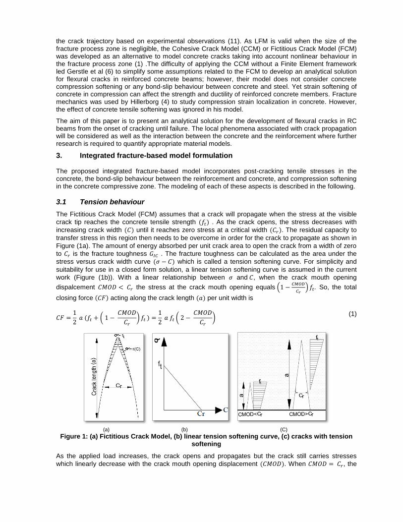
The Fictitious Crack Model (FCM) assumes that a crack will propagate when the stress at the visible
crack tip reaches the concrete tensile strength (𝑓𝑡) . As the crack opens, the stress decreases with
increasing crack width (𝐶) until it reaches zero stress at a critical width (𝐶𝑟). The residual capacity to
transfer stress in this region then needs to be overcome in order for the crack to propagate as shown in
Figure (1a). The amount of energy absorbed per unit crack area to open the crack from a width of zero
to 𝐶𝑟 is the fracture toughness 𝐺𝐼𝐶 . The fracture toughness can be calculated as the area under the
stress versus crack width curve (𝜎 − 𝐶) which is called a tension softening curve. For simplicity and
suitability for use in a closed form solution, a linear tension softening curve is assumed in the current
work (Figure (1b)). With a linear relationship between 𝜎 and 𝐶, when the crack mouth opening
dispalcement 𝐶𝑀𝑂𝐷 < 𝐶𝑟 the stress at the crack mouth opening equals (1 −𝐶𝑀𝑂𝐷
𝐶𝑟) 𝑓𝑡. So, the total
closing force (𝐶𝐹) acting along the crack length (𝑎) per unit width is
𝐶𝐹 =1
2 𝑎 (𝑓𝑡 + ( 1 −
𝐶𝑀𝑂𝐷
𝐶𝑟
) 𝑓𝑡 ) =1
2 𝑎 𝑓𝑡 ( 2 −
𝐶𝑀𝑂𝐷
𝐶𝑟
) (1)
(a) (b) (C)
Figure 1: (a) Fictitious Crack Model, (b) linear tension softening curve, (c) cracks with tension softening
As the applied load increases, the crack opens and propagates but the crack still carries stresses
which linearly decrease with the crack mouth opening displacement (𝐶𝑀𝑂𝐷). When 𝐶𝑀𝑂𝐷 = 𝐶𝑟, the
total closing force =1
2 𝑎 𝑓𝑡. As the crack propagates further and the crack opening exceeds 𝐶𝑟 at the
crack mouth (𝐶𝑀𝑂𝐷 > 𝐶𝑟), the total closing force (𝐶𝐹) then becomes
𝐶𝐹 =1
2 𝑎 𝑓𝑡 (
𝐶𝑟
𝐶𝑀𝑂𝐷)
(2)
3.2 Bond between reinforcement and concrete
Bond between reinforcement and concrete is necessary for reinforced concrete to act as a composite
material and to transfer load between the two materials. This interaction is represented in the literature
as shear stresses (𝜏) on the interface between the reinforcement and concrete. These stresses are
carried by different mechanisms such as mechanical interlock, chemical adhesion, and friction (12).
The relative contributions of these mechanisms depend on the concrete and reinforcement properties.
The development of bond stresses results in a relative displacement between the reinforcement and
the concrete parallel to the reinforcement axis called slip (𝑠). The bond- slip behaviour of reinforced
concrete affects the crack opening.
Based on test results on the local bond-slip relationship, Eligehausen et al (13) suggested a nonlinear
relationship with increasing 𝜏 and s when 0 ≤ 𝑠 ≤ 𝑠1 and until 𝜏 = 𝜏𝑚𝑎𝑥 . After the peak, the behaviour
can be modeled using a linear relationship between 𝜏 and s with a negative slope. Yuan et al (14) used
a bi-linear approximation (Figure (2)) to study the performance of the interface between fibre reinforced
polymers FRP and concrete. Mohamed Ali et al (15) further idealized a bi-linear relationship as a linear
descending relationship and demonstrated its applicability to steel reinforced concrete (Figure (2)). In
this case, the function that defines the bond-slip behaviour is
𝜏(𝑠) = 𝜏𝑚𝑎𝑥
𝑠𝑚𝑎𝑥
(𝑠𝑚𝑎𝑥 − 𝑠) (3)
where 𝜏𝑚𝑎𝑥 and 𝑠𝑚𝑎𝑥 are determined experimentally and depend on the concrete and steel properties.
Figure 2: Bi-linear bond-slip model and idealized linear bond-slip
The stress-strain behaviour of steel reinforcement is characterized by the elastic modulus 𝐸𝑠 until the steel yields at a stress 𝑓𝑦 . The post-yield behaviour can be approximated as a linear relationship
between the strain and stress but with a strain hardening modulus 𝐸𝑠ℎ (Figure (3)).
Haskett et al. (16) applied this steel stress-strain relationship and used an idealized linear bond-slip
model like that shown in Figure (2) to study reinforced concrete. The stress-slip distribution was
defined for two stages of behaviour. In the first stage the steel is elastic. During the second stage, the
steel yields and the distribution of the stress-slip changes according to the strain hardening modulus
𝐸𝑠ℎ . Considering the balance of forces and using a partial interaction numerical model, Haskett et al.
(16) developed relationships between the applied axial load and the slip at the crack face by treating
the elastic and the strain hardening behaviours separately and then summing them together. The
elastic steel force 𝑆𝐹𝑒𝑙 was calculated considering 𝐸s :
𝑆𝐹𝑒𝑙 = 𝜏𝑚𝑎𝑥 𝜋 𝑑
𝜆𝑒𝑙
sin {arccos {𝑠𝑚𝑎𝑥 − 𝑠
𝑠𝑚𝑎𝑥
}} (4)
where 𝜆𝑒𝑙 = √𝜋 𝑑 𝜏𝑚𝑎𝑥
𝑠𝑚𝑎𝑥 𝐸𝑠 𝐴𝑠 , 𝑑 is the diameter of the bar and 𝐴𝑠 is the area of the bar cross section.
The force after yielding 𝑆𝐹𝑠ℎ takes into account 𝐸𝑠ℎ :
𝑆𝐹𝑠ℎ = 𝜏𝑚𝑎𝑥 𝜋 𝑑
𝜆𝑠ℎ
sin {arccos {1 −𝑠 − 𝑠𝑦𝑖𝑒𝑙𝑑
𝑠𝑚𝑎𝑥
}} + 𝐴𝑠𝑓𝑦 (5)
where 𝜆𝑠ℎ = √𝜋 𝑑 𝜏𝑚𝑎𝑥
𝑠𝑚𝑎𝑥 𝐸𝑠ℎ 𝐴𝑠 and 𝑠𝑦𝑖𝑒𝑙𝑑 is the slip at yielding. For further details, please see (17) .
3.3 Compression behaviour
Most of the investigations that have been carried out on strain localization in concrete under compression are based on the uniaxial compression behaviour e.g. (18–21). However, the mechanical behaviour of reinforced concrete beams with strain localization in the compression zone has not been studied extensively. Hillerborg (4) developed a fracture mechanics- based model to study compression strain localization. He treated the compression localization in a manner similar to the localization that occurs in tensile fracture. According to his model, the compression behaviour can be described by means of stress-strain diagram until the peak compressive strength is reached and thereafter using a stress-deformation diagram. It was assumed that this localization takes place within a length proportional to the depth of the compression zone which changes with loading. Jansen & Shah (20) showed that the post-peak stress-deformation relationship is a material property and depends on the specimen size. Based on this assumption, Carpinteri et al. (9) developed the overlapping crack model where he refers to the deformation that occurs after the peak load as interpenetration. In this model, instead of identifying a length where strain localization occurs, it was assumed that strain localization develops gradually in the compression zone in a manner similar to cohesive models used to describe the tension zone. The proposed stress-deformation relationship was similar to Hillerborg’s. Based on the mathematical aspects of the overlapping model, a numerical algorithm was proposed (22) based on the finite element method to study the behaviour of RC beams. Borges et al. (23) adapted a linear softening curve (stress 𝜎𝑐 – strain ε response) (Figure(4)) which requires knowledge of the concrete
compressive strength concrete (𝑓𝑐) and the critical damage strain (𝜀𝑐𝑟) as material properties of concrete. According to this softening curve
𝜀 = 𝜀𝑐𝑟 (1 − 𝜎𝑐
𝑓𝑐
) (6)
Figure 4: Compression softening in concrete
The assumption of a linear relationship between the concrete compressive stress and strain allows for
an analytical solution for flexural cracking at the same time capturing the important features of the
behaviour.
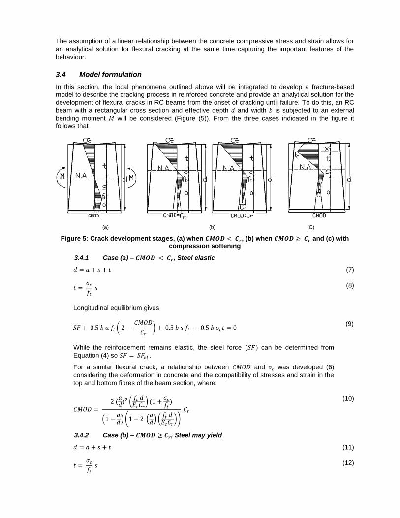
3.4 Model formulation
In this section, the local phenomena outlined above will be integrated to develop a fracture-based
model to describe the cracking process in reinforced concrete and provide an analytical solution for the
development of flexural cracks in RC beams from the onset of cracking until failure. To do this, an RC
beam with a rectangular cross section and effective depth 𝑑 and width 𝑏 is subjected to an external
bending moment 𝑀 will be considered (Figure (5)). From the three cases indicated in the figure it
follows that
(a) (b) (C)
Figure 5: Crack development stages, (a) when 𝑪𝑴𝑶𝑫 < 𝑪𝒓, (b) when 𝑪𝑴𝑶𝑫 ≥ 𝑪𝒓 and (c) with
compression softening
3.4.1 Case (a) – 𝑪𝑴𝑶𝑫 < 𝑪𝒓, Steel elastic
𝑑 = 𝑎 + 𝑠 + 𝑡 (7)
𝑡 = 𝜎𝑐
𝑓𝑡
𝑠 (8)
Longitudinal equilibrium gives
𝑆𝐹 + 0.5 𝑏 𝑎 𝑓𝑡 ( 2 − 𝐶𝑀𝑂𝐷
𝐶𝑟
) + 0.5 𝑏 𝑠 𝑓𝑡 − 0.5 𝑏 𝜎𝑐𝑡 = 0 (9)
While the reinforcement remains elastic, the steel force (𝑆𝐹) can be determined from
Equation (4) so 𝑆𝐹 = 𝑆𝐹𝑒𝑙 .
For a similar flexural crack, a relationship between 𝐶𝑀𝑂𝐷 and 𝜎𝑐 was developed (6)
considering the deformation in concrete and the compatibility of stresses and strain in the
top and bottom fibres of the beam section, where:
𝐶𝑀𝑂𝐷 = 2 (
𝑎𝑑
)2 (𝑓𝑡 𝑑𝐸𝑐𝐶𝑟
) (1 +𝜎𝑐
𝑓𝑡)
(1 −𝑎𝑑
) (1 − 2 (𝑎𝑑
) (𝑓𝑡 𝑑𝐸𝑐𝐶𝑟
))
𝐶𝑟
(10)
3.4.2 Case (b) – 𝑪𝑴𝑶𝑫 ≥ 𝑪𝒓, Steel may yield
𝑑 = 𝑎 + 𝑠 + 𝑡 (11)
𝑡 = 𝜎𝑐
𝑓𝑡
𝑠 (12)
Longitudinal equilibrium gives
𝑆𝐹 + 0.5 𝑏 𝑎 𝑓𝑡 ( 𝐶𝑟
𝐶𝑀𝑂𝐷) + 0.5 𝑏 𝑠 𝑓𝑡 − 0.5 𝑏 𝜎𝑐𝑡 = 0
(13)
If the steel remains in the elastic region, the steel force 𝑆𝐹 = 𝑆𝐹𝑒𝑙 and can be calculated from
Equation (4), and if the steel yields, the force after yielding can be calculated from Equation (5)
since 𝑆𝐹 = 𝑆𝐹𝑠ℎ.
Considering the relationship between 𝐶𝑀𝑂𝐷 and 𝜎𝑐 (6)
The steel force (𝑆𝐹) can be calculated from Equation (5)
The relationship between 𝐶𝑀𝑂𝐷 and 𝜎𝑐 for case (b) can be modified as
𝐶𝑀𝑂𝐷 =
2 (𝑎
𝑑 − 𝑥) (
𝑓𝑡 (𝑑 − 𝑥)𝐸𝑐𝐶𝑟
) (1 + (𝑎
𝑑 − 𝑥) (
𝑓𝑐
𝑓𝑡))
(1 −𝑎
𝑑 − 𝑥)
𝐶𝑟
(19)
Considering the three cases indicated above, the crack propagation of lightly reinforced concrete
beams can then be modelled by solving these equations for given steel and concrete properties.
4. Model results
A description of the cracking process is developed using the proposed model for different material
properties and beams at different sizes. Figure (6) shows the predicted dimensionless moment (M
fcb d2)
versus relative crack length (a
d) for an RC beam with the properties shown in the figure and for different
reinforcement ratios (0.14% - 2%) where 𝜏𝑚𝑎𝑥 and 𝐶𝑟 are material properties to be determined experimentally. There are some kinks in the graphs which indicate a change between different stages of behaviour. With sufficient reinforcement the crack propagates with increasing applied moment. However, with low reinforcement ratios, in some regions, the applied moment shows a decrease in capacity with crack propagation.
The model assumes a gradual loss of tensile strength with crack propagation and that the concrete loses its tensile strength completely when the crack mouth opening equals the critical crack opening
(𝐶𝑟). The point at which there is a decrease in the moment capacity is associated with the complete loss of the tensile stresses at the crack mouth as shown in Figure (6). Those stresses are then transferred to the reinforcement. If the reinforcement is not able to compensate for the loss of the concrete tensile stresses, the resistance decreases causing unstable crack propagation as noted for the beams with reinforcement ratios (0.14-0.77)% in Figure (6). Stable behaviour is associated with the development of the crack with increasing load whereas unstable behaviour is associated with the propagation of the crack under decreasing load. With higher reinforcement ratios, the crack propagation stage includes tensile softening until the tensile stresses diminish. If the stresses in the concrete exceed the compressive strength (𝑓𝑐), the concrete in compression exhibits a softening behaviour before failure and this depends on the geometrical and material properties.
Figure 6. Moment-crack length prediction for RC beams with different reinforcement ratios.
5. Comparison with test results
To check the theoretical predictions, comparisons with experimental test results were undertaken. In Figure (7) the predictions are compared with experimental data obtained by testing small scale concrete beams subjected to three-point bending. The beams had a width of 100mm, a depth of 120mm and a total length of 840 mm with reinforcement ratios of 0.28% and 0.5% and a concrete compressive strength of 30MPa or 45 MPa. The beams exhibited mode I fracture (crack opening) and during testing crack measurements were taken by means of a non-destructive digital image correlation technique. For further details of the test specimens and analysis techniques, please refer to (24). The beams were tested under displacement control. It is of note that to get a better indication of a decreasing branch of the crack length-moment diagram, the beams should be tested under CMOD controlled tests. This may be a reason why the descending branches in Figure (7) are not always captured; otherwise the model results show a good correlation with the experimental data.
b = 100mm d = 200 mm fc = 45MPa Ec = 39565 MPa ft = 5.6MPa fy = 540MPa 𝜏max = 9MPa
Es= 205600 MPa Cr = 0.074mm
(a) (b) (c)
Figure 7. Theoretical predictions versus experimental results.
6. Ductility in reinforced concrete
Ductility can be defined as the ability of a material to provide sufficient deformation, and hence warning prior to failure. Ductility is very important to ensure adequate warning before collapse. Carpinteri (10) proposed a dimensionless brittleness number based on his developed LEFM Bridged Crack Model to study the stability of the cracking process in lightly reinforced concrete beams and suggested a brittleness number 𝑁𝑝 (subsequently referred to as ductility number (25))
𝑁𝑝 = 𝑓𝑦 𝑑
12 𝐴𝑠
𝐾𝐼𝐶 𝐴
(20)
where 𝐾𝐼𝐶 is the critical stress intensity factor. Low values of 𝑁𝑝 are a sign of brittle behaviour and high
values give an indication of ductile behaviour.
The developed model includes further variables that are assumed to affect the cracking process. These variables include the beam depth 𝑑, beam width 𝑏, concrete compressive strength 𝑓𝑐,
reinforcement ratio 𝜌, critical crack mouth opening 𝐶𝑟, maximum shear stress between the reinforcement and concrete 𝜏𝑚𝑎𝑥, elastic modulus of concrete 𝐸𝑐 and elastic modulus of steel 𝐸𝑠.
Figure (8) shows the effect of 𝑓𝑐 and 𝜏𝑚𝑎𝑥 on the behaviour of a reinforced concrete beam. It is noted that for the given parameters decreasing the concrete compressive strength increases the stability of the cracking process; on the other hand, decreasing 𝜏𝑚𝑎𝑥 decreases the cracking stability.
(a) (b)
Figure 8: The effect of (a) concrete compressive strength (b) shear strength on the cracking
process
0
0.5
1
1.5
2
2.5
3
3.5
4
30 60 90 120
Mo
me
nt
(KN
.m)
Crack length (mm)
Analytical predictions
Experimental results
ρ = 0.28%,b = 100mmh = 120 mm,fc = 45MPa
0
0.5
1
1.5
2
2.5
3
3.5
4
30 60 90 120
Mo
me
nt
(KN
.m)
Crack length (mm)
Analytical predictionsExperimental results
0
0.5
1
1.5
2
2.5
3
3.5
4
30 60 90 120
Mo
me
nt
(KN
.m)
Crack length (mm)
Analytical predictions
Experimental results
ρ = 0.28%,b = 100mm h = 120 mm,fc = 30MPa
ρ = 0.50%,b = 100mm h = 120 mm,fc = 30MPa
ρ = 0.67%
b = 100mm
d = 300 mm
𝜏max = 9MPa
ρ = 0.67%
b = 100mm
d = 300 mm
fc = 45MPa
According to the developed model, it was found that in general increasing the values of 𝑑, 𝐶𝑟, 𝜌, 𝐸𝑠 and
𝜏𝑚𝑎𝑥 increase the stability of the cracking process and helps to avoid a brittle failure due to the fracture of the reinforcement which can lead to a more ductile behaviour. In contrast, increasing the values of 𝑓𝑐, 𝐸𝑐 and 𝑏 decrease the stability of the cracking process. Therefore, these properties should be reflected in a ductility measure to get a more representative indication of the ductility.
7. Conclusions
The proposed integrated fracture mechanics-based model is developed to describe the fracture process in reinforced concrete by integrating different local phenomena such as the tension softening of concrete to more precisely describe the behaviour of reinforced concrete beams. The model is capable of describing the initiation as well as the propagation of flexural cracks. Also, it is able to describe the post yielding behaviour as it considers the softening of concrete in compression and the strain hardening of the reinforcement after yielding. The bond between steel and concrete was modelled using a bond-slip model which gives a more accurate representation of the interaction between the concrete and the steel than the perfect bond assumption and helps to reveal the main parameters affecting the behaviour. Many assumptions related to the material behaviour were used to minimize the variables in the model to get a closed-form solution for the stresses associated with concrete cracking and the minimum reinforcement ratio, however, better accuracy can be achieved by implementing more sophisticated description of the material behaviour into the model i.e a non-linear softening behaviour can be assumed instead of linear behaviour.
8. Acknowledgements The authors would like to thank the Yousef Jameel Foundation for their financial support of this
research.
9. References 1. Hillerborg, A., Modéer, M., et al., “Analysis of crack formation and crack growth in concrete by
means of fracture mechanics and finite elements,” Cem. Concr. Res., vol. 6, no. 6, pp. 773–781, Nov. 1976.
2. Crisfield, M. A., “Local instabilities in the non-linear analysis of reinforced concrete beams and slabs,” Proc. Instn Civ. Engrs, Part 2, vol. 73, pp. 135–145, 1982.
3. Bažant, Z. P., Pan, J., et al., “Softening in Reinforced Concrete Beams and Frames,” J. Struct. Eng., vol. 113, no. 12, pp. 2333–2347, Dec. 1987.
4. Hillerborg, A., “Fracture mechanics concepts applied to moment capacity and rotational capacity of reinforced concrete beams,” Eng. Fract. Mech., vol. 35, no. l, pp. 233–240, 1990.
5. Chan, B. H. C., Cheung, Y. K., et al., “Crack analysis of reinforced concrete tension members,” vol. 118, pp. 2118–2132, 1993.
6. Gerstle, W. H., Dey, P. P., et al., “Crack growth in flexural members. A fracture mechanics approach,” ACI Struct. J., vol. 89, no. 89, pp. 617–625, 1992.
7. Ooi, E. T. and Yang, Z. J., “Modelling crack propagation in reinforced concrete using a hybrid finite element-scaled boundary finite element method,” Eng. Fract. Mech., vol. 78, no. 2, pp. 252–273, 2011.
8. Saleh, A. L. and Aliabadi, M. H., “Crack Growth Analysis in Reinforced Concrete Using BEM,” J. Eng. Mech., vol. 124, no. 9, pp. 949–958, Sep. 1998.
9. Carpinteri, A., Corrado, M., et al., “New Model for the Analysis of Size-Scale Effects on the Ductility of Reinforced Concrete Elements in Bending,” J. Eng. Mech., vol. 135, no. 3, pp. 221–229, Mar. 2009.
10. Carpinteri, A., “Stability of Fracturing Process in RC Beams,” J. Struct. Eng., vol. 110, no. 3, pp. 544–558, 1984.
11. Carpinteri, A., Ventura, G., et al., “Propagation of flexural and shear cracks through reinforced concrete beams by the bridged crack model,” Mag. Concr. Res., vol. 59, no. 10, pp. 743–756, Jan. 2007.
12. Lees, J. M. and Burgoyne, C. J., “Transfer bond stresses generated between FRP tendons and concrete,” Mag. Concr. Res., vol. 51, no. 4, pp. 229–239, Jan. 1999.
13. Eligehausen, R., Popov, E. P., et al., “Local bond stress-slip relationships of deformed bars under generalized excitations,” 1982.
14. Yuan, H., Teng, J. G., et al., “Full-range behaviour of FRP-to-concrete bonded joints,” Eng. Struct., vol. 26, pp. 553–565, 2004.
15. Mohamed Ali, M. S., Oehlers, D. J., et al., “Interfacial stress transfer of near surface-mounted FRP-to-concrete joints,” Eng. Struct., vol. 30, pp. 1861–1868, 2008.
16. Haskett, M., Oehlers, D. J., et al., “Rigid body moment-rotation mechanism for reinforced concrete beam hinges,” Eng. Struct., vol. 31, no. 5, pp. 1032–1041, 2009.
17. Haskett, M., Oehlers, D. J., et al., “Yield Penetration Hinge Rotation in Reinforced Concrete Beams,” J. Struct. Eng., vol. 135, no. February, pp. 130–138, 2009.
18. Torrenti, J. M., Benaija, E. H., et al., “Influence of boundary conditions on strain softening in concrete compression test,” J. Eng. Mech., vol. 119, pp. 2369–2384, 1993.
19. Markeset, G. and Hillerborg, A., “Softening of concrete in compression — Localization and size effects,” Cem. Concr. Res., vol. 25, no. 4, pp. 702–708, May 1995.
20. Jansen, D. C. and Shah, S. P., “Effect of Length on Compressive Strain Softening of Concrete,” J. Eng. Mech., vol. 123, no. January, pp. 25–35, 1997.
21. Watanabe, K., Niwa, J., et al., “Localized failure of concrete in compression identified by AE method,” Constr. Build. Mater., vol. 18, pp. 189–196, 2004.
22. Carpinteri, A., Corrado, M., et al., “An integrated cohesive/overlapping crack model for the analysis of flexural cracking and crushing in RC beams,” Int. J. Fract., vol. 161, no. 2, pp. 161–173, Feb. 2010.
23. Borges, J. U. A, Subramaniam, K. V., et al., “Length effect on ductility of concrete in uniaxial and flexural compression,” ACI Struct. J., vol. 101, no. 101, pp. 765–772, 2004.
24. Fayyad, T. M. and Lees, J. M., “Application of Digital Image Correlation to Reinforced Concrete Fracture,” Procedia Mater. Sci., vol. 3, pp. 1585–1590, 2014.
25. Carpinteri, A., Cadamuro, E., et al., “Minimum flexural reinforcement in rectangular and T-section concrete beams,” Struct. Concr., vol. 15, no. 3, pp. 361–372, 2014.