Note: This test report was prepared for the customer shown above and for the device described herein. It may not be duplicated or used in part without prior written consent from Bay Area Compliance Laboratories Corp. (Chengdu). Any unauthorized alteration, forgery or falsification of the content or appearance of this document is unlawful and offenders may be prosecuted to the fullest extent of the law. This report was valid only with a valid digital signature. FCC PART 15.407 TEST REPORT For SZ DJI TECHNOLOGY CO., LTD 14th floor, West Wing, Skyworth Semiconductor Design Building NO.18 Gaoxin South 4th Ave, Nanshan, Shenzhen, Guangdong, China Report Type: Original Report Product Name: Inspire 2 Test Engineer: Lorin Bian Report Number: RDG160813002B Report Date: 2016-10-20 Reviewed By: Henry Ding EMC Leader Test Laboratory: Bay Area Compliance Laboratories Corp. (Chengdu) 5040, HuiLongWan Plaza, No. 1, ShaWan Road, JinNiu District, ChengDu, China Tel: 028-65523123, Fax: 028-65525125 www.baclcorp.com FCC ID: SS3-T650A1609
Transcript
Note: This test report was prepared for the customer shown above and for the device described herein. It may not be duplicated or used in part without prior written consent from Bay Area Compliance Laboratories Corp. (Chengdu). Any unauthorized alteration, forgery or falsification of the content or appearance of this document is unlawful and offenders may be prosecuted to the fullest extent of the law. This report was valid only with a valid digital signature.
FCC PART 15.407
TEST REPORT
For
SZ DJI TECHNOLOGY CO., LTD
14th floor, West Wing, Skyworth Semiconductor Design Building NO.18 Gaoxin South 4th Ave, Nanshan, Shenzhen, Guangdong, China
Report Type:
Original Report
Product Name:
Inspire 2
Test Engineer: Lorin Bian
Report Number:
RDG160813002B
Report Date: 2016-10-20
Reviewed By:
Henry Ding EMC Leader
Test Laboratory: Bay Area Compliance Laboratories Corp. (Chengdu) 5040, HuiLongWan Plaza, No. 1, ShaWan Road, JinNiu District, ChengDu, China Tel: 028-65523123, Fax: 028-65525125 www.baclcorp.com
FCC ID: SS3-T650A1609
Bay Area Compliance Laboratories Corp. (Chengdu)
Report No.: RDG160813002B Page 2 of 32
TABLE OF CONTENTS GENERAL INFORMATION ........................................................................................................................................ 3
PRODUCT DESCRIPTION FOR EQUIPMENT UNDER TEST (EUT) ................................................................................ 3 OBJECTIVE .................................................................................................................................................................. 3 RELATED SUBMITTAL(S)/GRANT(S) ............................................................................................................................ 3 TEST METHODOLOGY ................................................................................................................................................. 3 TEST FACILITY ............................................................................................................................................................. 4
SYSTEM TEST CONFIGURATION ........................................................................................................................... 5 DESCRIPTION OF TEST CONFIGURATION ................................................................................................................... 5 EUT EXERCISE SOFTWARE ........................................................................................................................................ 5 EQUIPMENT MODIFICATIONS ...................................................................................................................................... 6 BLOCK DIAGRAM OF TEST SETUP .............................................................................................................................. 6
SUMMARY OF TEST RESULTS ............................................................................................................................... 8
FCC §15.407 (f) & §1.1310 & §2.1091- MAXIMUM PERMISSIBLE EXPOSURE (MPE) ...................................... 9 APPLICABLE STANDARD .............................................................................................................................................. 9
FCC §15.203 – ANTENNA REQUIREMENT ......................................................................................................... 10 APPLICABLE STANDARD ............................................................................................................................................ 10 ANTENNA CONNECTOR CONSTRUCTION .................................................................................................................. 10
FCC §15.209, §15.205 & §15.407(b) (1) (6) (7) –UNWANTED EMISSION ..................................................... 11 APPLICABLE STANDARD ............................................................................................................................................ 11 MEASUREMENT UNCERTAINTY ................................................................................................................................. 12 EUT SETUP ............................................................................................................................................................... 13 EMI TEST RECEIVER & SPECTRUM ANALYZER SETUP ........................................................................................... 14 TEST PROCEDURE .................................................................................................................................................... 14 CORRECTED AMPLITUDE & MARGIN CALCULATION ................................................................................................. 14 TEST EQUIPMENT LIST AND DETAILS ....................................................................................................................... 15 TEST DATA ................................................................................................................................................................ 15
FCC §15.407(a) –EMISSION BANDWIDTH AND OCCUPIED BANDWIDTH ................................................. 18 APPLICABLE STANDARD ............................................................................................................................................ 18 TEST EQUIPMENT LIST AND DETAILS ....................................................................................................................... 18 TEST PROCEDURE .................................................................................................................................................... 18 TEST DATA ............................................................................................................................................................... 18
FCC §15.407(a) –MAXIMUM CONDUCTED OUTPUT POWER ........................................................................ 21 APPLICABLE STANDARD ............................................................................................................................................ 21 TEST EQUIPMENT LIST AND DETAILS ....................................................................................................................... 22 TEST PROCEDURE .................................................................................................................................................... 22 TEST DATA ................................................................................................................................................................ 23
FCC §15.407(a) - POWER SPECTRAL DENSITY ............................................................................................... 24 APPLICABLE STANDARD ............................................................................................................................................ 24 TEST PROCEDURE .................................................................................................................................................... 25 TEST EQUIPMENT LIST AND DETAILS ....................................................................................................................... 25 TEST DATA ................................................................................................................................................................ 25
Bay Area Compliance Laboratories Corp. (Chengdu)
Report No.: RDG160813002B Page 3 of 32
GENERAL INFORMATION Product Description for Equipment under Test (EUT) The SZ DJI TECHNOLOGY CO., LTD’s product, model number: T650A (FCC ID: SS3-T650A1609) (the "EUT") in this report was an Inspire 2, which was measured approximately: 470 mm (L) x 440 mm (W) x 330 mm(H), rated input voltage: DC 22.8V from lithium battery.
*All measurement and test data in this report was gathered from final production sample, serial number: 160813002 (assigned by the BACL, Chengdu). It may have deviation from any other sample. The EUT supplied by the applicant was received on 2016-08-13, and EUT conformed to test requirement.
Objective This type approval report is prepared on behalf of SZ DJI TECHNOLOGY CO., LTD in accordance with Part 2-Subpart J, Part 15-Subparts A, B and E of the Federal Communications Commission’s rules. The tests were performed in order to determine compliance with FCC Part 15, Subpart E, section 15.203, 15.205, 15.207, 15.209 and 15.407 rules. Related Submittal(s)/Grant(s) FCC Part 15.247 DTS submissions with FCC ID: SS3-T650A1609. Part of system submissions with FCC ID: SS3-GL6D10A1609. Test Methodology All measurements contained in this report were conducted with ANSI C63.10-2013, American National Standard of Procedures for Compliance Testing of Unlicensed Wireless Devices. All emissions measurement was performed and Bay Area Compliance Laboratories Corp. (Chengdu). The radiated testing was performed at an antenna-to-EUT distance of 3 meters. The uncertainty of any RF tests which use conducted method measurement is ±3.17 dB, the uncertainty of any radiation on emissions measurement is: 30M~200MHz: ±4.7 dB; 200M~1GHz: ±6.0 dB; 1G-6GHz:: ±5.13dB; 6G~25GHz: ±5.47dB; And the uncertainty will not be taken into consideration for all test data recorded in the report.
Bay Area Compliance Laboratories Corp. (Chengdu)
Report No.: RDG160813002B Page 4 of 32
Test Facility The test site used by BACL to collect test data is located in the 5040, HuiLongWan Plaza, No. 1, ShaWan Road, JinNiu District, ChengDu, China Test site at BACL has been fully described in reports submitted to the Federal Communication Commission (FCC). The details of these reports have been found to be in compliance with the requirements of Section 2.948 of the FCC Rules on April 24, 2015. The facility also complies with the radiated and AC line conducted test site criteria set forth in ANSI C63.4-2014. The Federal Communications Commission has the reports on file and is listed under FCC Registration No.: 560332. The test site has been approved by the FCC for public use and is listed in the FCC Public Access Link (PAL) database.
Bay Area Compliance Laboratories Corp. (Chengdu)
Report No.: RDG160813002B Page 5 of 32
SYSTEM TEST CONFIGURATION Description of Test Configuration The system was configured for testing in Engineering Mode, which was provided by the manufacturer. For5.8GHz band, 24 channels are provided:
3channels were tested: 5730MHz, 5790MHz, 5845MHz The device employed 4 internal antennas, support 2T2R MIMO mode, the system configures two of them transmitting and two receiving depending on better performance by the system automatically recognizes. For antenna port conducted test items, based on output power testing, the two highest power ports was chose for full test. EUT Exercise Software The software “DJI-RF Certification” was used for testing, which was provided by manufacturer. The maximum power and duty cycle was configured by system default setting. The default setting level as below:
Test Software Version DJI-RF Certification
Frequency (MHz) 5730 5790 5845
Power Level Setting 25 25 25 The duty cycle as below:
Ton (ms)
Ton+off (ms)
Duty Cycle (%)
10.43 14.04 74.29% The minimum transmission duration(T) is 10.43ms.
Bay Area Compliance Laboratories Corp. (Chengdu)
Report No.: RDG160813002B Page 6 of 32
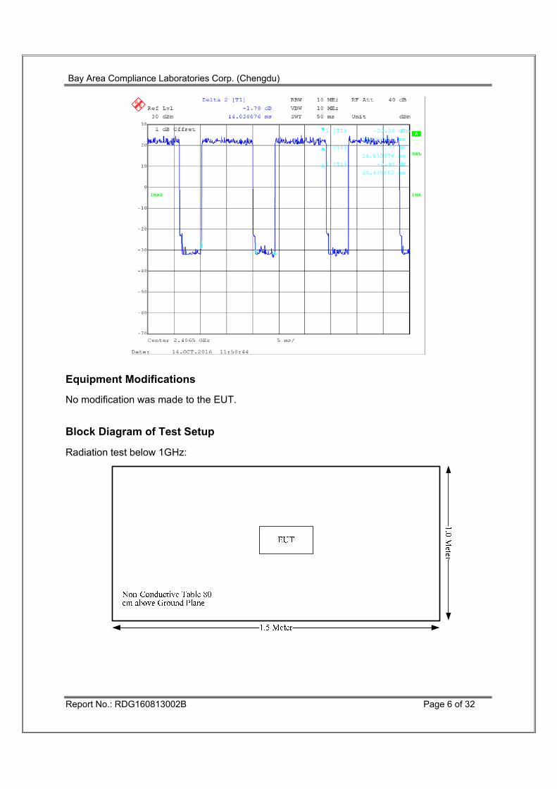
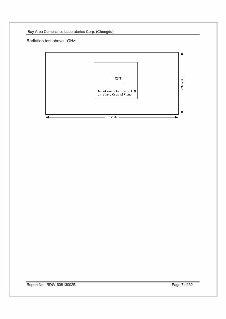
Equipment Modifications No modification was made to the EUT. Block Diagram of Test Setup Radiation test below 1GHz:
§15.407(b) (1),(2),(3),(4) Out Of Band Emissions Compliant
§15.407(a) 6 dB Bandwidth Compliant
§15.407(a)(1), Conducted Transmitter Output Power Compliant
§15.407 (a)(1),(5) Power Spectral Density Compliant
Bay Area Compliance Laboratories Corp. (Chengdu)
Report No.: RDG160813002B Page 9 of 32
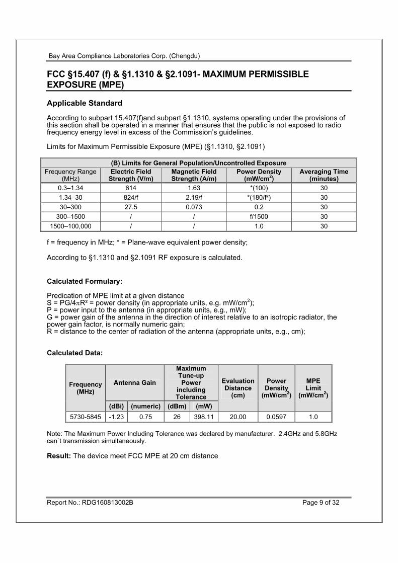
FCC §15.407 (f) & §1.1310 & §2.1091- MAXIMUM PERMISSIBLE EXPOSURE (MPE) Applicable Standard According to subpart 15.407(f)and subpart §1.1310, systems operating under the provisions of this section shall be operated in a manner that ensures that the public is not exposed to radio frequency energy level in excess of the Commission’s guidelines. Limits for Maximum Permissible Exposure (MPE) (§1.1310, §2.1091)
(B) Limits for General Population/Uncontrolled Exposure Frequency Range
f = frequency in MHz; * = Plane-wave equivalent power density; According to §1.1310 and §2.1091 RF exposure is calculated.
Calculated Formulary: Predication of MPE limit at a given distance S = PG/4πR² = power density (in appropriate units, e.g. mW/cm2); P = power input to the antenna (in appropriate units, e.g., mW); G = power gain of the antenna in the direction of interest relative to an isotropic radiator, the power gain factor, is normally numeric gain; R = distance to the center of radiation of the antenna (appropriate units, e.g., cm); Calculated Data:
Frequency (MHz)
Antenna Gain
Maximum Tune-up Power
including Tolerance
EvaluationDistance
(cm)
Power Density
(mW/cm2)
MPE Limit
(mW/cm2) (dBi) (numeric) (dBm) (mW)
5730-5845 -1.23 0.75 26 398.11 20.00 0.0597 1.0 Note: The Maximum Power Including Tolerance was declared by manufacturer. 2.4GHz and 5.8GHz can`t transmission simultaneously. Result: The device meet FCC MPE at 20 cm distance
Bay Area Compliance Laboratories Corp. (Chengdu)
Report No.: RDG160813002B Page 10 of 32
FCC §15.203 – ANTENNA REQUIREMENT Applicable Standard According to § 15.203, an intentional radiator shall be designed to ensure that no antenna other than that furnished by the responsible party shall be used with the device. The use of a permanently attached antenna or of an antenna that uses a unique coupling to the intentional radiator shall be considered sufficient to comply with the provisions of this section. The manufacturer may design the unit so that a broken antenna can be replaced by the user, but the use of a standard antenna jack or electrical connector is prohibited. And according to FCC 47 CFR section 15.407 (a)(1),if transmitting antennas of directional gain greater than 6 dBi are used, both the maximum conducted output power and the peak power spectral density shall be reduced by the amount in dB that the directional gain of the antenna exceeds 6 dBi. Antenna Connector Construction The EUT has 4 internal antennas arrangement, and the antennas gain are 0.74 [email protected], -1.23dBi@5GHz, fulfill the requirement of the item. Please refer to the internal photos. Result: Compliance.
(b) Undesirable emission limits. Except as shown in paragraph (b)(7) of this section, the maximum emissions outside of the frequency bands of operation shall be attenuated in accordance with the following limits:
(1) For transmitters operating in the 5.15-5.25 GHz band: All emissions outside of the 5.15-5.35 GHz band shall not exceed an e.i.r.p. of −27 dBm/MHz.
(2) For transmitters operating in the 5.25-5.35 GHz band: All emissions outside of the 5.15-5.35 GHz band shall not exceed an e.i.r.p. of −27 dBm/MHz.
(3) For transmitters operating in the 5.47-5.725 GHz band: All emissions outside of the 5.47-5.725 GHz band shall not exceed an e.i.r.p. of −27 dBm/MHz.
(4) For transmitters operating in the 5.725-5.85 GHz band:
(i) All emissions shall be limited to a level of −27 dBm/MHz at 75 MHz or more above or below the band edge increasing linearly to 10 dBm/MHz at 25 MHz above or below the band edge, and from 25 MHz above or below the band edge increasing linearly to a level of 15.6 dBm/MHz at 5 MHz above or below the band edge, and from 5 MHz above or below the band edge increasing linearly to a level of 27 dBm/MHz at the band edge.
(ii) Devices certified before March 2, 2017 with antenna gain greater than 10 dBi may demonstrate compliance with the emission limits in §15.247(d), but manufacturing, marketing and importing of devices certified under this alternative must cease by March 2, 2018. Devices certified before March 2, 2018 with antenna gain of 10 dBi or less may demonstrate compliance with the emission limits in §15.247(d), but manufacturing, marketing and importing of devices certified under this alternative must cease before March 2, 2020.
(5) The emission measurements shall be performed using a minimum resolution bandwidth of 1 MHz. A lower resolution bandwidth may be employed near the band edge, when necessary, provided the measured energy is integrated to show the total power over 1 MHz.
(6) Unwanted emissions below 1 GHz must comply with the general field strength limits set forth in §15.209. Further, any U-NII devices using an AC power line are required to comply also with the conducted limits set forth in §15.207.
(7) The provisions of §15.205 apply to intentional radiators operating under this section.
Bay Area Compliance Laboratories Corp. (Chengdu)
Report No.: RDG160813002B Page 12 of 32
Measurement Uncertainty Compliance or non- compliance with a disturbance limit shall be determined in the following manner: If Ulab is less than or equal to Ucispr of Table 1, then: –compliance is deemed to occur if no measured disturbance level exceeds the disturbance limit; –non - compliance is deemed to occur if any measured disturbance level exceeds the disturbance limit. If Ulab is greater than Ucispr of Table 1, then: –compliance is deemed to occur if no measured disturbance level, increased by (Ulab − Ucispr), exceeds the disturbance limit; –non - compliance is deemed to occur if any measured disturbance level, increased by (Ulab − Ucispr), exceeds the disturbance limit. Based on CISPR 16-4-2-2011, measurement uncertainty of radiated emission at a distance of 3m at Bay Area Compliance Laboratories Corp. (Chengdu) is: 30M~200MHz: ±4.7 dB ; 200M~1GHz: ±6.0 dB ; 1G-6GHz: ±5.13dB; 6G~25GHz: ±5.47 dB;
Table 1 – Values of Ucispr
Measurement Ucispr
Radiated disturbance (electric field strength at an OATS or in a SAC) (30 MHz to 1000 MHz) Radiated disturbance (electric field strength in a FAR) (1 GHz to 6 GHz) Radiated disturbance (electric field strength in a FAR) (6 GHz to 18 GHz)
6.3 dB5.2 dB5.5 dB
Bay Area Compliance Laboratories Corp. (Chengdu)
Report No.: RDG160813002B Page 13 of 32
EUT Setup Below 1 GHz: Above 1 GHz: The radiated emission tests were performed in the 3 meters chamber, using the setup accordance with the ANSI C63.10-2013. The specification used was the FCC 15.209, and FCC 15.407 limits.
Bay Area Compliance Laboratories Corp. (Chengdu)
Report No.: RDG160813002B Page 14 of 32
EMI Test Receiver & Spectrum Analyzer Setup The system was investigated from 30 MHz to 40 GHz. During the radiated emission test, the EMI test receiver & Spectrum Analyzer Setup were set with the following configurations: 30MHz-1000MHz:
Detector RBW Video B/W IF B/W QP 120 kHz 300 kHz 120kHz
1GHz- 40GHz:
Detector Duty cycle RBW Video B/W PK Any 1MHz 3 MHz
Ave. >98% 1MHz 10 Hz <98% 1MHz 1/T
Note: T is minimum transmission duration Test Procedure During the radiated emission test, the adapter was connected to the first AC floor outlet and the other support equipments were connected to the second AC floor outlet. Maximizing procedure was performed on the highest emissions to ensure that the EUT complied with all installation combinations. Data was recorded in Quasi-peak detection mode for frequency range of 30 MHz-1GHz, peak and Average detection modes for frequencies above 1GHz. According to KDB 789033 D02 General UNII Test Procedures New Rules v01r03, emission shall be computed as: E [dBμV/m] = EIRP[dBm] + 95.2, for d = 3 meters. According to C63.10, the above 1G test result shall be extrapolated to the specified distance using an extrapolation factor of 20dB/decade from 3m to 1.5m Distance extrapolation factor =20 log (specific distance [3m]/test distance [1.5m]) dB Extrapolation result = Corrected Amplitude (dBμV/m) - distance extrapolation factor (6dB) Corrected Amplitude & Margin Calculation The Corrected Amplitude is calculated by adding the Antenna Loss and Cable Loss, and subtracting the Amplifier Gain from the Meter Reading. The basic equation is as follows:
Corrected Amplitude = Meter Reading + Antenna Loss + Cable Loss - Amplifier Gain The “Margin” column of the following data tables indicates the degree of compliance with the applicable limit. For example, a margin of 7dB means the emission is 7dB below the limit. The equation for margin calculation is as follows:
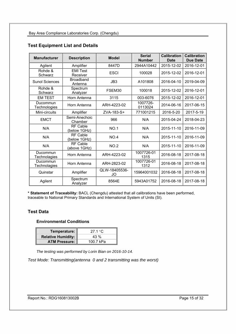
* Statement of Traceability: BACL (Chengdu) attested that all calibrations have been performed, traceable to National Primary Standards and International System of Units (SI). Test Data
Environmental Conditions
Temperature: 27.1 °C Relative Humidity: 43 %
ATM Pressure: 100.7 kPa
The testing was performed by Lorin Bian on 2016-10-14. Test Mode: Transmitting(antenna 0 and 2 transmitting was the worst)
Bay Area Compliance Laboratories Corp. (Chengdu)
Report No.: RDG160813002B Page 16 of 32
30MHz-40GHz(Test performed at 3.0m distance EUT to antenna)
Frequency Receiver Rx Antenna Cable loss(dB)
AmplifierGain (dB)
Corrected Amplitude (dBμV/m)
Limit (dBμV/m)
Margin(dB) (MHz) Reading
(dBμV) Detector
(PK/QP/AV) Polar(H/V)
Factor(dB)
Low Channel:5730 MHz 5730 74.58 PK H 32.58 5.72 0.00 112.88 N/A N/A5730 60.97 AV H 32.58 5.72 0.00 99.27 N/A N/A5730 78.59 PK V 32.58 5.72 0.00 116.89 N/A N/A5730 65.49 AV V 32.58 5.72 0.00 103.79 N/A N/A5725 52.69 PK V 32.57 5.72 0.00 90.98 122.00 31.02 5720 51.22 PK V 32.56 5.71 0.00 89.49 110.80 21.31 5700 31.26 PK V 32.54 5.70 26.63 42.87 105.20 62.33 5650 27.42 PK V 32.48 5.65 26.63 38.92 68.20 29.28 11460 30.22 PK V 37.97 8.22 26.02 50.39 74.00 23.61 11460 20.71 AV V 37.97 8.22 26.02 40.88 54.00 13.12 17190 33.52 PK V 42.77 10.75 25.93 61.11 74.00 12.89 17190 23.25 AV V 42.77 10.75 25.93 50.84 54.00 3.16 5035 35.62 PK V 31.46 5.06 26.86 45.28 74.00 28.72 5035 22.69 AV V 31.46 5.06 26.86 32.35 54.00 21.65 3145 34.58 PK V 25.01 3.65 26.46 36.78 74.00 37.22 3145 25.71 AV V 25.01 3.65 26.46 27.91 54.00 26.09
312.27 33.34 QP V 14.41 1.15 27.58 21.32 46.00 24.68 648.86 26.93 QP V 20.28 1.94 28.85 20.30 46.00 25.70
Middle Channel:5790 MHz 5785 73.99 PK H 32.64 5.77 0.00 112.40 N/A N/A5785 60.78 AV H 32.64 5.77 0.00 99.19 N/A N/A5785 79.81 PK V 32.64 5.77 0.00 118.22 N/A N/A5785 64.69 AV V 32.64 5.77 0.00 103.10 N/A N/A11580 31.96 PK V 38.03 8.21 26.00 52.20 74.00 21.80 11580 21.69 AV V 38.03 8.21 26.00 41.93 54.00 12.07 17370 33.71 PK V 43.60 11.05 26.19 62.17 74.00 11.83 17370 20.69 AV V 43.60 11.05 26.19 49.15 54.00 4.85 5020 34.57 PK V 31.44 5.05 26.87 44.19 74.00 29.81 5020 21.54 AV V 31.44 5.05 26.87 31.16 54.00 22.84 7060 34.29 PK V 34.42 6.10 26.29 48.52 74.00 25.48 7060 22.71 AV V 34.42 6.10 26.29 36.94 54.00 17.06
312.27 34.25 QP V 14.41 1.15 27.58 22.23 46.00 23.77 648.86 27.93 QP V 20.28 1.94 28.85 21.30 46.00 24.70
Bay Area Compliance Laboratories Corp. (Chengdu)
Report No.: RDG160813002B Page 17 of 32
High Channel:5845 MHz
5845 72.97 PK H 32.71 5.82 0.00 111.50 N/A N/A5845 59.59 AV H 32.71 5.82 0.00 98.12 N/A N/A5845 79.05 PK V 32.71 5.82 0.00 117.58 N/A N/A5845 64.27 AV V 32.71 5.82 0.00 102.80 N/A N/A5850 52.09 PK V 32.72 5.83 0.00 90.64 122.20 31.56 5855 50.47 PK V 32.73 5.83 0.00 89.03 110.80 21.77 5875 31.29 PK V 32.75 5.85 26.65 43.24 105.20 61.96 5925 26.87 PK V 32.81 5.89 26.65 38.92 68.20 29.28 11690 31.58 PK V 38.08 8.19 25.97 51.88 74.00 22.12 11690 20.72 AV V 38.08 8.19 25.97 41.02 54.00 12.98 17535 33.75 PK V 44.31 11.22 26.33 62.95 74.00 11.05 17535 20.69 AV V 44.31 11.22 26.33 49.89 54.00 4.11 5020 34.78 PK V 31.44 5.05 26.87 44.40 74.00 29.60 5020 22.39 AV V 31.44 5.05 26.87 32.01 54.00 21.99 6835 33.18 PK V 34.00 6.09 26.35 46.92 74.00 27.08 6835 21.93 AV V 34.00 6.09 26.35 35.67 54.00 18.33
312.27 34.58 QP V 14.41 1.15 27.58 22.56 46.00 23.44 648.86 28.14 QP V 20.28 1.94 28.85 21.51 46.00 24.49
Note: Marker-delta method used in the band-edge test.
Bay Area Compliance Laboratories Corp. (Chengdu)
Report No.: RDG160813002B Page 18 of 32
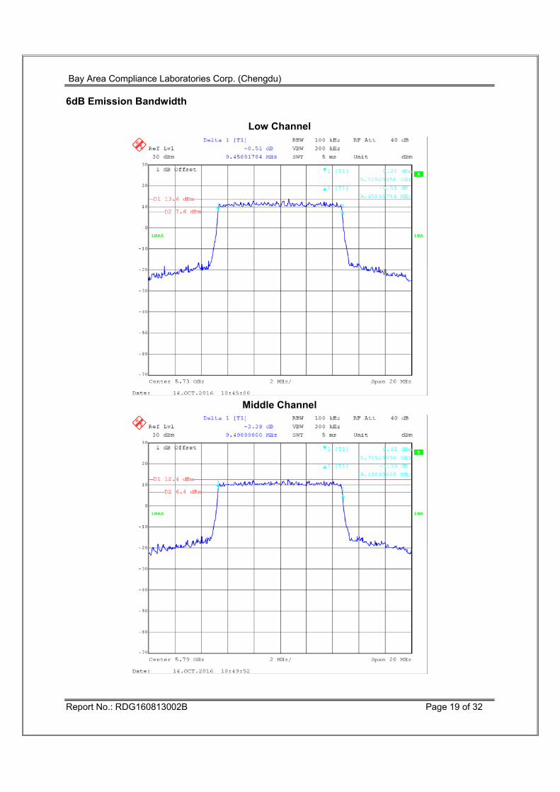
FCC §15.407(a) –EMISSION BANDWIDTH AND OCCUPIED BANDWIDTH Applicable Standard 15.407(a) (e) Test Equipment List and Details
Manufacturer Description Model Serial Number Calibration Date
Calibration Due Date
Rohde & Schwarz Signal Analyzer FSIQ26 831929/005 2016-09-21 2017-09-20
N/A RF Cable N/A N/A Each Time /
* Statement of Traceability: BACL (Chengdu) attested that all calibrations have been performed, traceable to National Primary Standards and International System of Units (SI). Test Procedure According to KDB 789033 D02 General UNII Test Procedures New Rules v01r03 Test Data
Environmental Conditions
Temperature: 27.3 °C Relative Humidity: 32 %
ATM Pressure: 100.6 kPa
The testing was performed by Lorin Bian on 2016-10-14. Test Result: Pass. Please refer to the following tables and plots.
Test mode: Transmitting(Test only performed at Chain 0)
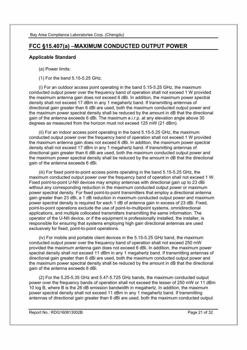
FCC §15.407(a) –MAXIMUM CONDUCTED OUTPUT POWER Applicable Standard
(a) Power limits:
(1) For the band 5.15-5.25 GHz.
(i) For an outdoor access point operating in the band 5.15-5.25 GHz, the maximum conducted output power over the frequency band of operation shall not exceed 1 W provided the maximum antenna gain does not exceed 6 dBi. In addition, the maximum power spectral density shall not exceed 17 dBm in any 1 megahertz band. If transmitting antennas of directional gain greater than 6 dBi are used, both the maximum conducted output power and the maximum power spectral density shall be reduced by the amount in dB that the directional gain of the antenna exceeds 6 dBi. The maximum e.i.r.p. at any elevation angle above 30 degrees as measured from the horizon must not exceed 125 mW (21 dBm).
(ii) For an indoor access point operating in the band 5.15-5.25 GHz, the maximum conducted output power over the frequency band of operation shall not exceed 1 W provided the maximum antenna gain does not exceed 6 dBi. In addition, the maximum power spectral density shall not exceed 17 dBm in any 1 megahertz band. If transmitting antennas of directional gain greater than 6 dBi are used, both the maximum conducted output power and the maximum power spectral density shall be reduced by the amount in dB that the directional gain of the antenna exceeds 6 dBi.
(iii) For fixed point-to-point access points operating in the band 5.15-5.25 GHz, the maximum conducted output power over the frequency band of operation shall not exceed 1 W. Fixed point-to-point U-NII devices may employ antennas with directional gain up to 23 dBi without any corresponding reduction in the maximum conducted output power or maximum power spectral density. For fixed point-to-point transmitters that employ a directional antenna gain greater than 23 dBi, a 1 dB reduction in maximum conducted output power and maximum power spectral density is required for each 1 dB of antenna gain in excess of 23 dBi. Fixed, point-to-point operations exclude the use of point-to-multipoint systems, omnidirectional applications, and multiple collocated transmitters transmitting the same information. The operator of the U-NII device, or if the equipment is professionally installed, the installer, is responsible for ensuring that systems employing high gain directional antennas are used exclusively for fixed, point-to-point operations.
(iv) For mobile and portable client devices in the 5.15-5.25 GHz band, the maximum conducted output power over the frequency band of operation shall not exceed 250 mW provided the maximum antenna gain does not exceed 6 dBi. In addition, the maximum power spectral density shall not exceed 11 dBm in any 1 megahertz band. If transmitting antennas of directional gain greater than 6 dBi are used, both the maximum conducted output power and the maximum power spectral density shall be reduced by the amount in dB that the directional gain of the antenna exceeds 6 dBi.
(2) For the 5.25-5.35 GHz and 5.47-5.725 GHz bands, the maximum conducted output power over the frequency bands of operation shall not exceed the lesser of 250 mW or 11 dBm 10 log B, where B is the 26 dB emission bandwidth in megahertz. In addition, the maximum power spectral density shall not exceed 11 dBm in any 1 megahertz band. If transmitting antennas of directional gain greater than 6 dBi are used, both the maximum conducted output
Bay Area Compliance Laboratories Corp. (Chengdu)
Report No.: RDG160813002B Page 22 of 32
power and the maximum power spectral density shall be reduced by the amount in dB that the directional gain of the antenna exceeds 6 dBi.
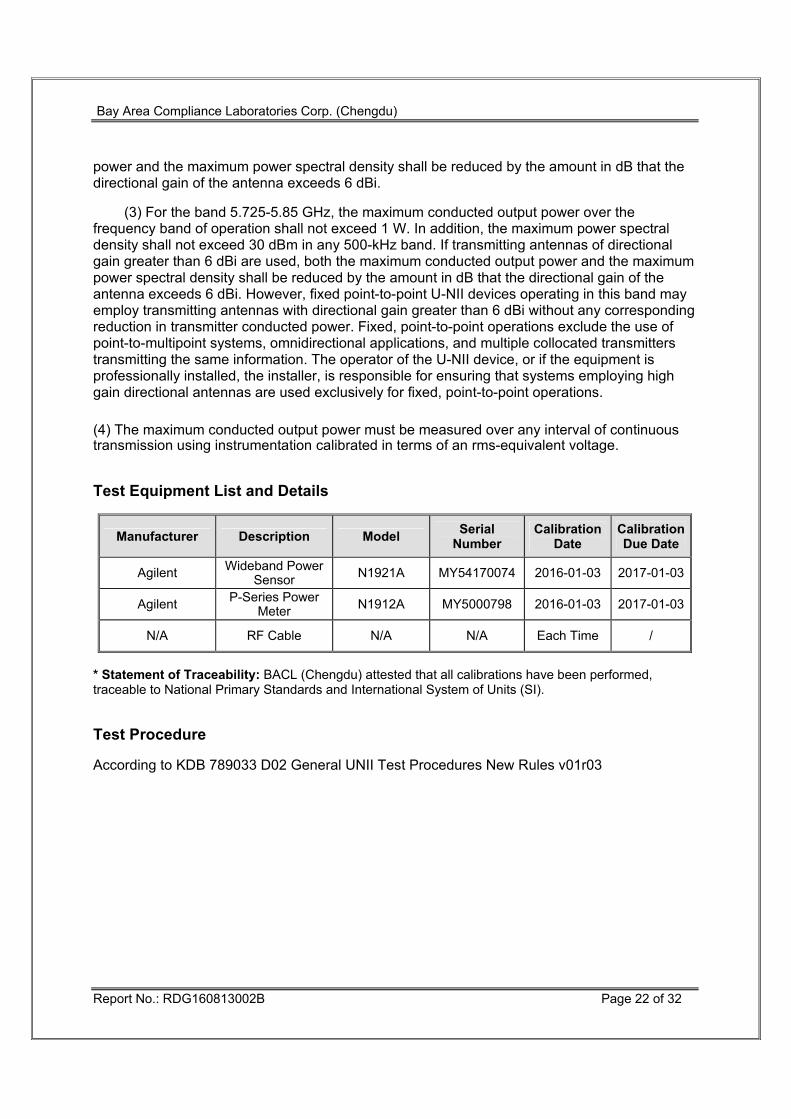
(3) For the band 5.725-5.85 GHz, the maximum conducted output power over the frequency band of operation shall not exceed 1 W. In addition, the maximum power spectral density shall not exceed 30 dBm in any 500-kHz band. If transmitting antennas of directional gain greater than 6 dBi are used, both the maximum conducted output power and the maximum power spectral density shall be reduced by the amount in dB that the directional gain of the antenna exceeds 6 dBi. However, fixed point-to-point U-NII devices operating in this band may employ transmitting antennas with directional gain greater than 6 dBi without any corresponding reduction in transmitter conducted power. Fixed, point-to-point operations exclude the use of point-to-multipoint systems, omnidirectional applications, and multiple collocated transmitters transmitting the same information. The operator of the U-NII device, or if the equipment is professionally installed, the installer, is responsible for ensuring that systems employing high gain directional antennas are used exclusively for fixed, point-to-point operations. (4) The maximum conducted output power must be measured over any interval of continuous transmission using instrumentation calibrated in terms of an rms-equivalent voltage. Test Equipment List and Details
Manufacturer Description Model Serial Number
Calibration Date
Calibration Due Date
Agilent Wideband Power Sensor N1921A MY54170074 2016-01-03 2017-01-03
Agilent P-Series Power Meter N1912A MY5000798 2016-01-03 2017-01-03
N/A RF Cable N/A N/A Each Time /
* Statement of Traceability: BACL (Chengdu) attested that all calibrations have been performed, traceable to National Primary Standards and International System of Units (SI). Test Procedure According to KDB 789033 D02 General UNII Test Procedures New Rules v01r03
Bay Area Compliance Laboratories Corp. (Chengdu)
Report No.: RDG160813002B Page 23 of 32
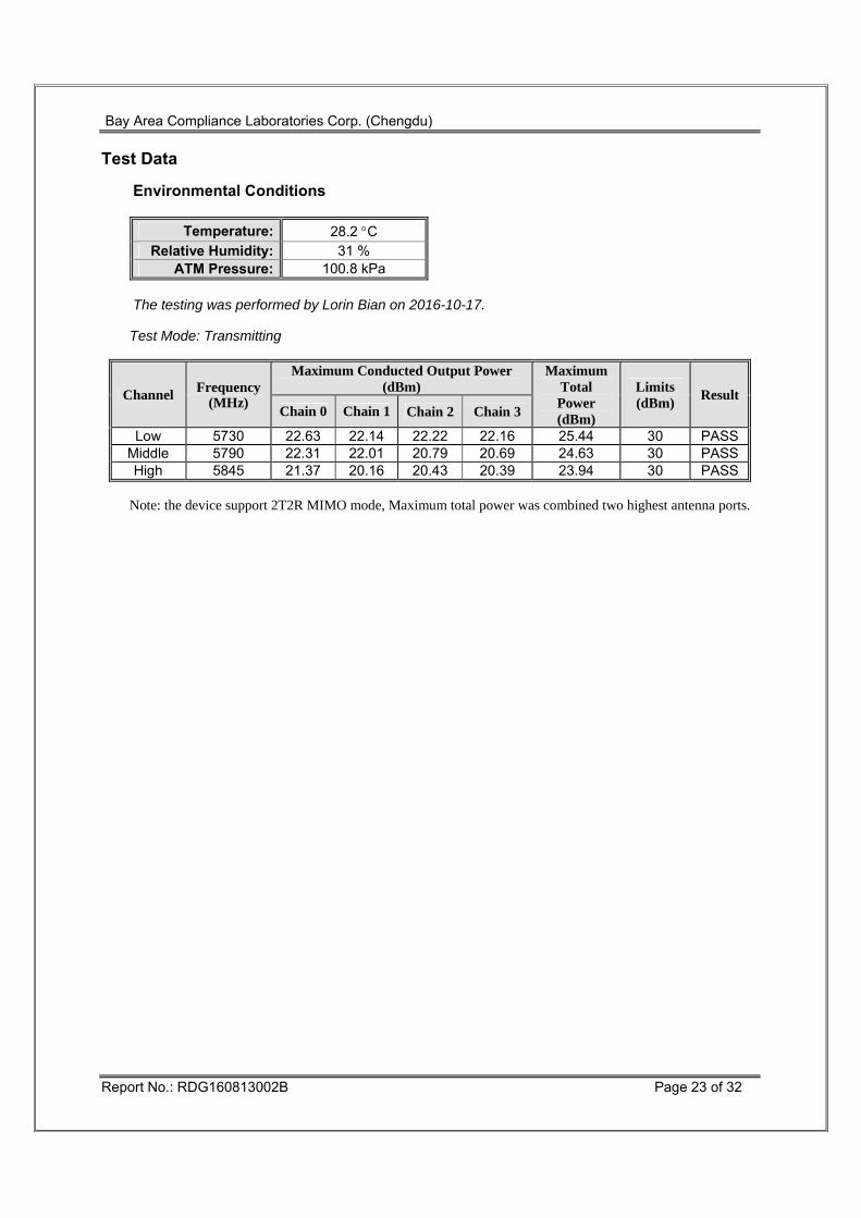
Test Data
Environmental Conditions
Temperature: 28.2 °C Relative Humidity: 31 %
ATM Pressure: 100.8 kPa
The testing was performed by Lorin Bian on 2016-10-17.
Test Mode: Transmitting
Channel Frequency(MHz)
Maximum Conducted Output Power (dBm)
Maximum Total Power (dBm)
Limits (dBm) Result
Chain 0 Chain 1 Chain 2 Chain 3
Low 5730 22.63 22.14 22.22 22.16 25.44 30 PASSMiddle 5790 22.31 22.01 20.79 20.69 24.63 30 PASSHigh 5845 21.37 20.16 20.43 20.39 23.94 30 PASS Note: the device support 2T2R MIMO mode, Maximum total power was combined two highest antenna ports.
Bay Area Compliance Laboratories Corp. (Chengdu)
Report No.: RDG160813002B Page 24 of 32
FCC §15.407(a) - POWER SPECTRAL DENSITY Applicable Standard
(a) Power limits:
(1) For the band 5.15-5.25 GHz.
(i) For an outdoor access point operating in the band 5.15-5.25 GHz, the maximum conducted output power over the frequency band of operation shall not exceed 1 W provided the maximum antenna gain does not exceed 6 dBi. In addition, the maximum power spectral density shall not exceed 17 dBm in any 1 megahertz band. If transmitting antennas of directional gain greater than 6 dBi are used, both the maximum conducted output power and the maximum power spectral density shall be reduced by the amount in dB that the directional gain of the antenna exceeds 6 dBi. The maximum e.i.r.p. at any elevation angle above 30 degrees as measured from the horizon must not exceed 125 mW (21 dBm).
(ii) For an indoor access point operating in the band 5.15-5.25 GHz, the maximum conducted output power over the frequency band of operation shall not exceed 1 W provided the maximum antenna gain does not exceed 6 dBi. In addition, the maximum power spectral density shall not exceed 17 dBm in any 1 megahertz band. If transmitting antennas of directional gain greater than 6 dBi are used, both the maximum conducted output power and the maximum power spectral density shall be reduced by the amount in dB that the directional gain of the antenna exceeds 6 dBi.
(iii) For fixed point-to-point access points operating in the band 5.15-5.25 GHz, the maximum conducted output power over the frequency band of operation shall not exceed 1 W. Fixed point-to-point U-NII devices may employ antennas with directional gain up to 23 dBi without any corresponding reduction in the maximum conducted output power or maximum power spectral density. For fixed point-to-point transmitters that employ a directional antenna gain greater than 23 dBi, a 1 dB reduction in maximum conducted output power and maximum power spectral density is required for each 1 dB of antenna gain in excess of 23 dBi. Fixed, point-to-point operations exclude the use of point-to-multipoint systems, omnidirectional applications, and multiple collocated transmitters transmitting the same information. The operator of the U-NII device, or if the equipment is professionally installed, the installer, is responsible for ensuring that systems employing high gain directional antennas are used exclusively for fixed, point-to-point operations.
(iv) For mobile and portable client devices in the 5.15-5.25 GHz band, the maximum conducted output power over the frequency band of operation shall not exceed 250 mW provided the maximum antenna gain does not exceed 6 dBi. In addition, the maximum power spectral density shall not exceed 11 dBm in any 1 megahertz band. If transmitting antennas of directional gain greater than 6 dBi are used, both the maximum conducted output power and the maximum power spectral density shall be reduced by the amount in dB that the directional gain of the antenna exceeds 6 dBi.
(2) For the 5.25-5.35 GHz and 5.47-5.725 GHz bands, the maximum conducted output power over the frequency bands of operation shall not exceed the lesser of 250 mW or 11 dBm 10 log B, where B is the 26 dB emission bandwidth in megahertz. In addition, the maximum power spectral density shall not exceed 11 dBm in any 1 megahertz band. If transmitting antennas of directional gain greater than 6 dBi are used, both the maximum conducted output
Bay Area Compliance Laboratories Corp. (Chengdu)
Report No.: RDG160813002B Page 25 of 32
power and the maximum power spectral density shall be reduced by the amount in dB that the directional gain of the antenna exceeds 6 dBi.
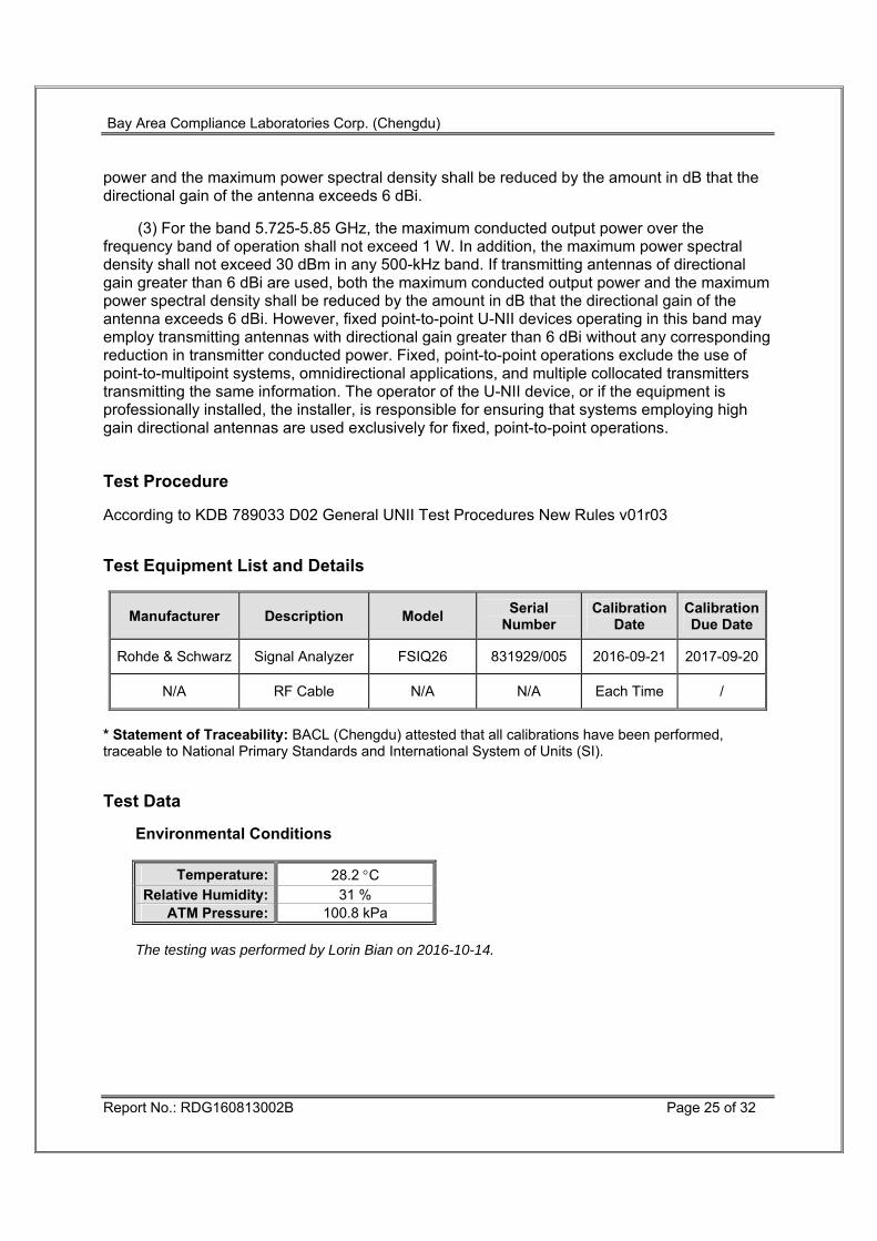
(3) For the band 5.725-5.85 GHz, the maximum conducted output power over the frequency band of operation shall not exceed 1 W. In addition, the maximum power spectral density shall not exceed 30 dBm in any 500-kHz band. If transmitting antennas of directional gain greater than 6 dBi are used, both the maximum conducted output power and the maximum power spectral density shall be reduced by the amount in dB that the directional gain of the antenna exceeds 6 dBi. However, fixed point-to-point U-NII devices operating in this band may employ transmitting antennas with directional gain greater than 6 dBi without any corresponding reduction in transmitter conducted power. Fixed, point-to-point operations exclude the use of point-to-multipoint systems, omnidirectional applications, and multiple collocated transmitters transmitting the same information. The operator of the U-NII device, or if the equipment is professionally installed, the installer, is responsible for ensuring that systems employing high gain directional antennas are used exclusively for fixed, point-to-point operations. Test Procedure According to KDB 789033 D02 General UNII Test Procedures New Rules v01r03 Test Equipment List and Details
Manufacturer Description Model Serial Number
Calibration Date
Calibration Due Date
Rohde & Schwarz Signal Analyzer FSIQ26 831929/005 2016-09-21 2017-09-20
N/A RF Cable N/A N/A Each Time /
* Statement of Traceability: BACL (Chengdu) attested that all calibrations have been performed, traceable to National Primary Standards and International System of Units (SI). Test Data
Environmental Conditions
Temperature: 28.2 °C Relative Humidity: 31 %
ATM Pressure: 100.8 kPa
The testing was performed by Lorin Bian on 2016-10-14.
Bay Area Compliance Laboratories Corp. (Chengdu)
Report No.: RDG160813002B Page 26 of 32
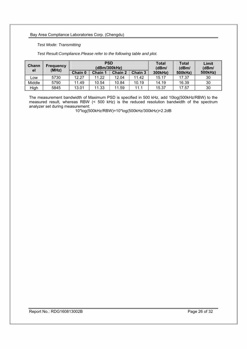
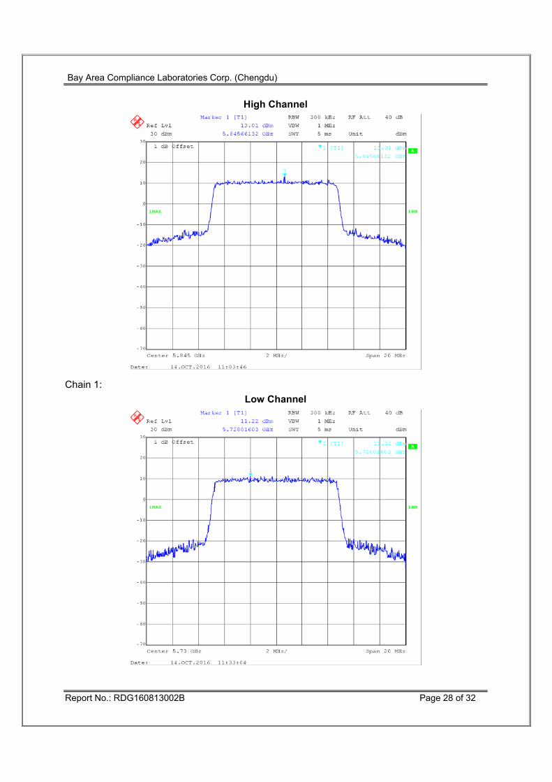
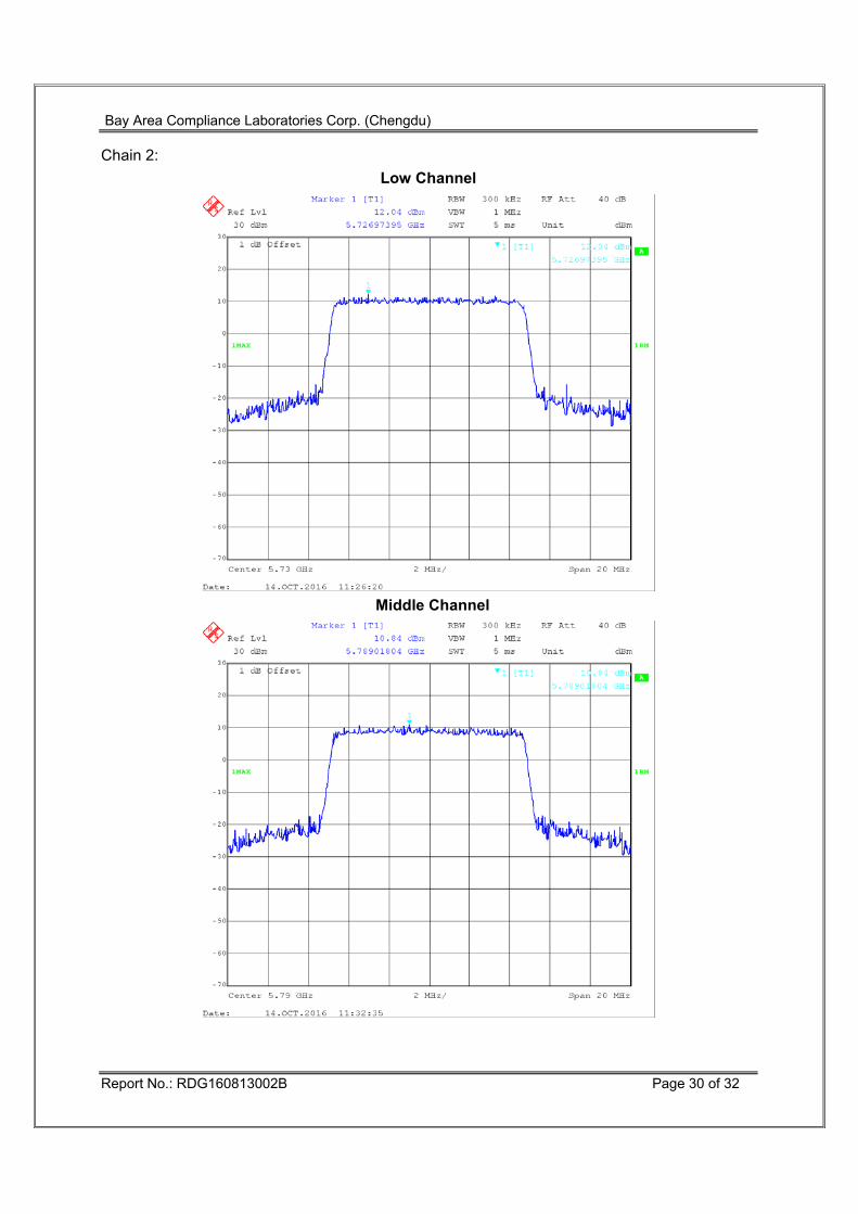
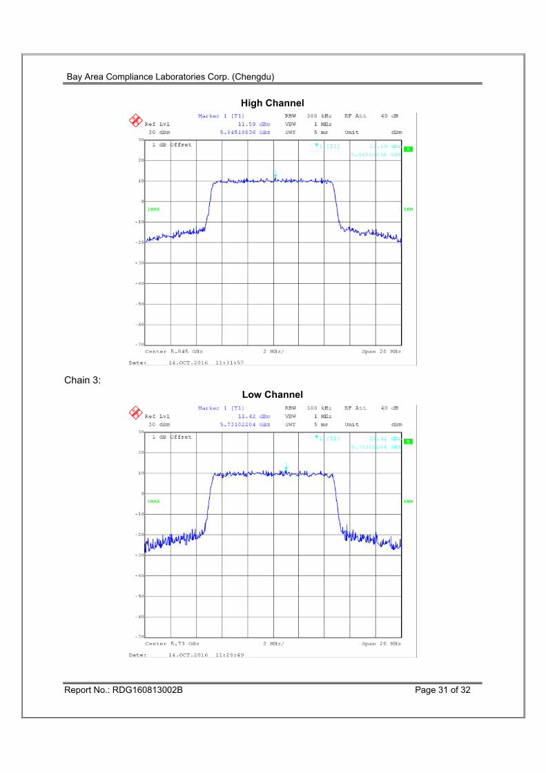
Test Mode: Transmitting Test Result:Compliance.Please refer to the following table and plot.
Middle 5790 11.49 10.54 10.84 10.19 14.19 16.39 30 High 5845 13.01 11.33 11.59 11.1 15.37 17.57 30 The measurement bandwidth of Maximum PSD is specified in 500 kHz, add 10log(500kHz/RBW) to the measured result, whereas RBW (< 500 kHz) is the reduced resolution bandwidth of the spectrum analyzer set during measurement:


![933 dji phantom-4 spec-sheet-rev[1] - PLASTICASE · 2019. 10. 23. · 933 DJI™ PHANTOM 4 For all DJI™ Phantom 4 models Phantom 4 Phantom 4 Pro Phantom 4 Pro + 2.0 Phantom 4 RTK](https://static.documents.pub/doc/80x56/60c827405a7e465133218fc4/933-dji-phantom-4-spec-sheet-rev1-plasticase-2019-10-23-933-djia-phantom.jpg)