Shenzhen Toby Technology Co., Ltd. Report No.: TB-FCC150690 Page: 1 of 17 TB-RF-074-1.0 1A/F., Bldg.6, Yusheng Industrial Zone, The National Road No.107 Xixiang Section 467, Xixiang, Bao’an, Shenzhen, China Tel: +86 75526509301 Fax: +86 75526509195 FCC Part 15B Test Report Application No. : TB161114348 Applicant : BRANDO TECHNOLOGY CO., LTD. Equipment Under Test (EUT) EUT Name : Charger rack Model No. : BO-CR-30 Series Model No. : N/A Brand Name : BRANDO Receipt Date : 2016-11-24 Test Date : 2016-11-24 to 2016-11-28 Issue Date : 2016-11-28 Standards : FCC Part 15:2015 Subpart B Class A Conclusions : PASS In the configuration tested, the EUT complied with the standards specified above The EUT technically complies with the FCC requirements Test/Witness Engineer : Approved & Authorized : This report details the results of the testing carried out on one sample. The results contained in this test report do not relate to other samples of the same product. The manufacturer should ensure that all products in series production are in conformity with the product sample detailed in the report.
Transcript
Shenzhen Toby Technology Co., Ltd.
Report No.: TB-FCC150690
Page: 1 of 17
TB-RF-074-1.0
1A/F., Bldg.6, Yusheng Industrial Zone, The National Road No.107 Xixiang Section 467, Xixiang, Bao’an, Shenzhen, China
Tel: +86 75526509301 Fax: +86 75526509195
FCC Part 15B Test Report
Application No. : TB161114348
Applicant : BRANDO TECHNOLOGY CO., LTD.
Equipment Under Test (EUT)
EUT Name : Charger rack
Model No. : BO-CR-30
Series Model No. : N/A
Brand Name : BRANDO
Receipt Date : 2016-11-24
Test Date : 2016-11-24 to 2016-11-28
Issue Date : 2016-11-28
Standards : FCC Part 15:2015 Subpart B Class A
Conclusions : PASS
In the configuration tested, the EUT complied with the standards specified above
The EUT technically complies with the FCC requirements
Test/Witness Engineer :
Approved & Authorized :
This report details the results of the testing carried out on one sample. The results contained in this test report do not relate to other samples of the same product. The manufacturer should ensure that all products in series production are in conformity with the product sample detailed in the report.
1.3 Block Diagram Showing The Configuration of System Tested
1.4 Description of Support Units
The EUT has been tested as an independent unit.
Power Supply EUT
Report No.: TB-FCC150690
Page: 4 of 17
TB-RF-074-1.0
1.5 Test standards
The objective is to determine compliance with FCC Part 15, Subpart B, and section 15.107, 15.109 rules. Maintenance of compliance is the responsibility of the manufacturer. Any modification of the product, which result in lowering the emission, should be checked to ensure compliance has been maintained.
1.6 Test Facility
The testing report were performed by the Shenzhen Toby Technology Co., Ltd., in their facilities located at 1A/F., Bldg.6, Yusheng Industrial Zone, The National Road No.107 Xixiang Section 467, Xixiang, Bao’an, Shenzhen, Guangdong, China. At the time of testing, the following bodies accredited the Laboratory: CNAS (L5813) The Laboratory has been accredited by CNAS to ISO/IEC 17025: 2005 General Requirements for the Competence of Testing and Calibration Laboratories for the competence in the field of testing. And the Registration No.: CNAS L5813. FCC List No.: (811562) The Laboratory is listed in the United States of American Federal Communications Commission (FCC), and the registration number is 811562. IC Registration No.: (11950A-1) The Laboratory has been registered by Certification and Engineering Bureau of Industry Canada for radio equipment testing. The site registration: Site# 11950A-1.
Report No.: TB-FCC150690
Page: 5 of 17
TB-RF-074-1.0
1.7 Equipment Used Test
Conducted Emission Test
Equipment Manufacturer Model No. Serial No. Last Cal. Cal.Due
Bilog Antenna ETS-LINDGREN 3142E 00117537 Mar. 20, 2016 Mar. 19, 2017
Horn Antenna ETS-LINDGREN 3117 00143207 Mar. 19, 2016 Mar. 18, 2017
Pre-amplifier Sonoma 310N 185903 Mar. 20, 2016 Mar. 19, 2017
Pre-amplifier HP 8447B 3008A00849 Mar. 26, 2016 Mar. 25, 2017
Cable HUBER+SUHNER 100 SUCOFLEX Mar. 26, 2016 Mar. 25, 2017
Positioning
Controller ETS-LINDGREN 2090 N/A N/A N/A
Report No.: TB-FCC150690
Page: 6 of 17
TB-RF-074-1.0
2. Test Summary
Test Items Test Requirement Test Method Result
Conducted Emission FCC Part 15:2015 Subpart B
Class A 15.107 ANSI C63.4 Pass
Radiated Emission FCC Part 15:2015 Subpart B
Class A 15.109 ANSI C63.4 Pass
Note:
(1) N/A is an abbreviation for Not Applicable.
(2) The equipment is a Class A digital device, and it is marketed for use in a commercial, industrial or
business environment. More details please read the user manual of the equipment.
Report No.: TB-FCC150690
Page: 7 of 17
TB-RF-074-1.0
3. Conducted Emission Test
3.1 Test Standard and Limit
3.1.1Test Standard FCC Part 15 B: 2015; 15.107
3.1.2 Test Limit
Conducted Emission Test Limit (Class A)
Frequency Maximum RF Line Voltage (dBV)
Quasi-peak Level Average Level 150kHz~500kHz 79 66 500kHz~30MHz 73 60
*decreasing linearly with logarithm of the frequency
3.2 Test Setup
3.3 Test Procedure
The EUT was placed 0.15 meters from the horizontal ground plane with EUT being connected to the power mains through a line impedance stabilization network (LISN). All other support equipments powered from additional LISN(s). The LISN provide 50 Ohm/ 50uH of coupling impedance for the measuring instrument.
0.15m
Report No.: TB-FCC150690
Page: 8 of 17
TB-RF-074-1.0
The cables shall be insulated (by up to 15 cm) from the horizontal ground reference plane, and shall be folded back and forth in the center forming a bundle 30 to 40 cm long.
I/O cables that are not connected to a peripheral shall be bundled in the center. The end of the cable may be terminated, if required, using the correct terminating impedance. The overall length shall not exceed 1 m. LISN at least 80 cm from nearest part of EUT chassis. The bandwidth of EMI test receiver is set at 9kHz, and the test frequency band is from 0.15MHz to 30MHz.
3.4 Test Condition
Temperature : 25 ℃ Relative Humidity : 48 % Pressure : 1010 hPa Test Power : AC 120V/60Hz
3.5 Test Data
Please refer to the following pages.
Report No.: TB-FCC150690
Page: 9 of 17
TB-RF-074-1.0
EUT: Charger rack Model Name : BO-CR-30
Temperature: 25 ℃ Relative Humidity: 55%
Test Voltage: AC 120V/60 Hz
Terminal: Line
Test Mode: Normal Mode
Remark: N/A
Emission Level= Read Level+ Correct Factor
Report No.: TB-FCC150690
Page: 10 of 17
TB-RF-074-1.0
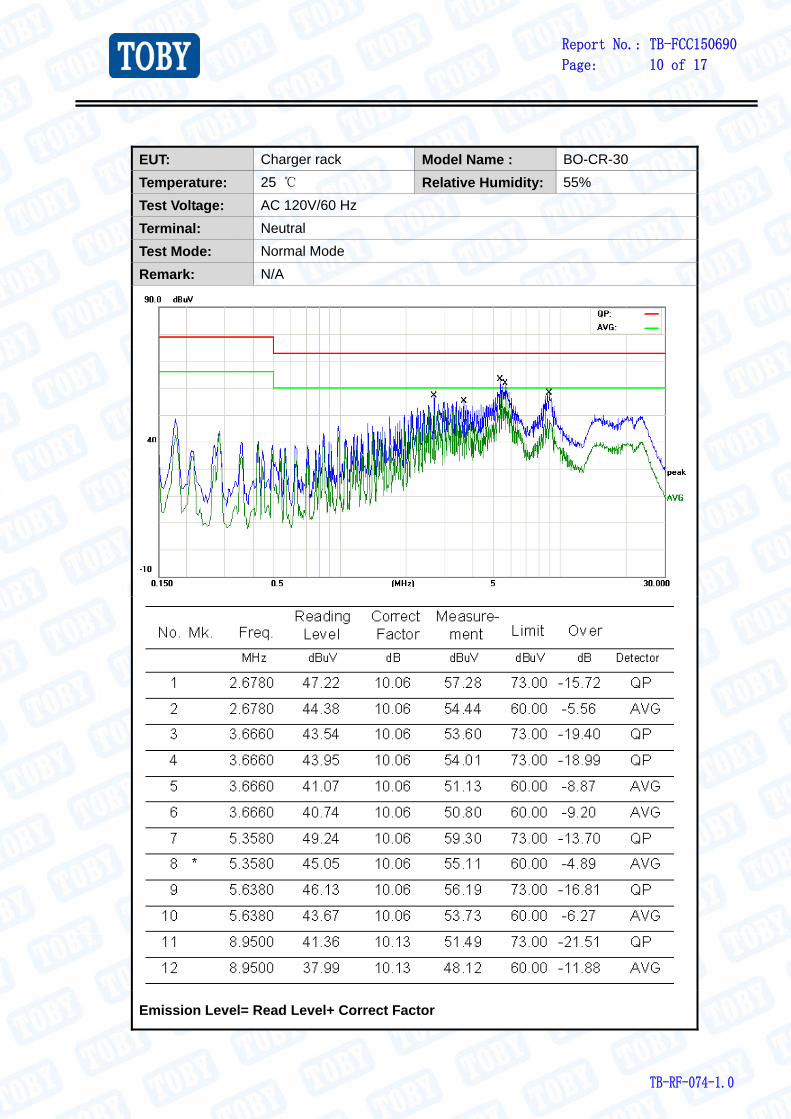
EUT: Charger rack Model Name : BO-CR-30
Temperature: 25 ℃ Relative Humidity: 55%
Test Voltage: AC 120V/60 Hz
Terminal: Neutral
Test Mode: Normal Mode
Remark: N/A
Emission Level= Read Level+ Correct Factor
Report No.: TB-FCC150690
Page: 11 of 17
TB-RF-074-1.0
4. Radiated Emission Test
4.1 Test Standard and Limit
4.1.1 Test Standard FCC Part 15 B: 2015; 15.109
4.1.2 Test Limit Radiated Emission Test Limit (Class A)
Frequency MHz
Field Strengths Limits dB(V/m)
30 ~ 88 49.0 88 ~ 216 53.5
216 ~ 960 56.5 960 ~ 1000 59.5
* The lower limit shall apply at the transition frequency.
* The test distance is 3m.
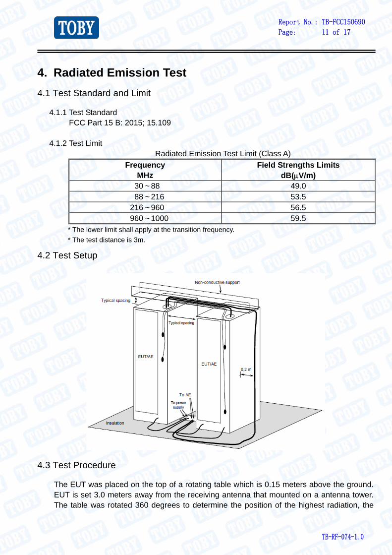
4.2 Test Setup
4.3 Test Procedure
The EUT was placed on the top of a rotating table which is 0.15 meters above the ground. EUT is set 3.0 meters away from the receiving antenna that mounted on a antenna tower. The table was rotated 360 degrees to determine the position of the highest radiation, the
Report No.: TB-FCC150690
Page: 12 of 17
TB-RF-074-1.0
antenna can be moved up and down between 1.0 meter and 4 meters to find out the maximum emission level. Both horizontal and vertical polarizations of the antenna are set to make the measurement. Measurements shall be made with a quasi-peak measuring receiver in the frequency range 30MHz to 1000MHz. If the Peak Mode measured value compliance with and lower than quasi-peak mode Limit, the EUT shall be deemed to meet QP Limits and then no additional QP Mode measurement performed.
4.4 Test Condition
Temperature : 25 ℃ Relative Humidity : 48 % Pressure : 1010 hPa Test Power : AC 120V/60Hz